

Page 1
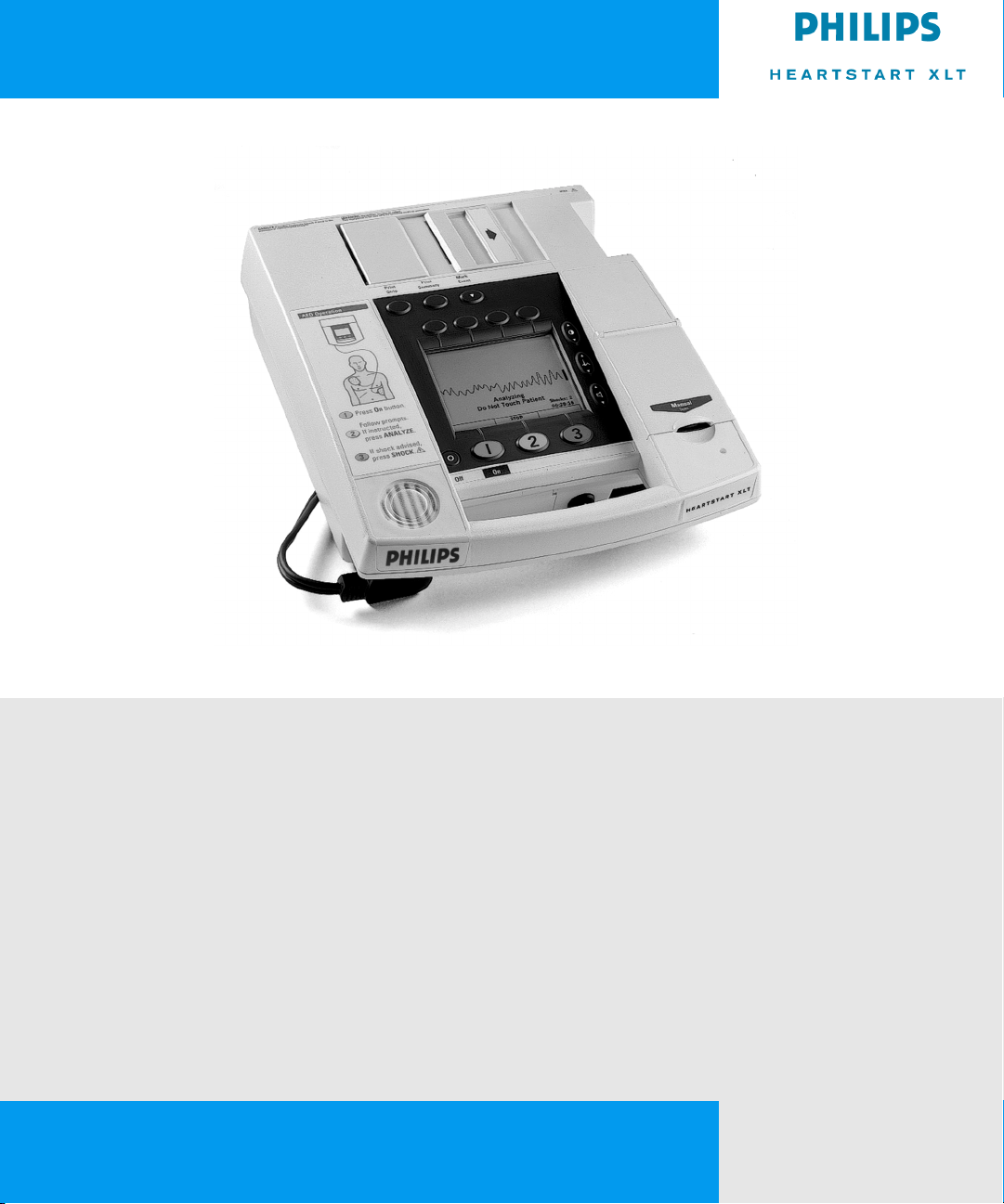
HEARTSTART XLT
INSTRUCTIONS FOR USE
M3500B
Page 2

Page 3

Instructions for Use
0%+HDUW6WDUW;/7
'HILEULOODWRU0RQLWRU
Page 4

1RWLFH
About This Edition
Edition 3
Printed in the USA
Publication nu mber M3500-91900
The information in this gui de a pplie s to
the M3500B HeartStart XLT, release
Main 35 and earlier. This informatio n is
subject to change without n otice.
Philips Medical Systems shall not be
liable for errors contained herein or for
incidental or consequential damages in
connection with the furnishing, performance, or use of this material.
Edition History
Edition 1, January 3, 2000
Edition 2, May 15, 2000
Edition 3, October 30, 2002
Copyright
Copyright © 2002
Philips Electronics North America
Corporation
3000 Minuteman Road
Andover, MA USA 01810-1099
(978) 687-1501
All rights are reserved. Reproduction in
whole or in part is prohibited without
the prior written consent of the copyright holder.
SMART Biphasic is a registered trademark of Philips Medical Systems.
Use of supplies or accessories other
than those recommended by Philips
Medical Systems may compromise
product perfor ma n ce .
THIS PRODUCT IS NOT INTENDED
FOR HOME USE.
IN THE U.S., FEDERAL LAW
RESTRICTS THIS DEVICE TO SALE
ON OR BY THE ORDER OF A PHYSICIAN.
Medical Device Directive
The M3500B HeartStart XLT Defibrillator/Monitor complies with the
requirements of the Medical Dev ice
Directive 93/42/EEC and carries the
mark accordingly.
0123
Authorized EU-representative:
Philips Medizinsysteme Böblingen
GmbH
Hewlett Packard Str. 2
71034 Böblingen
Germany
Canada EMC:ICES -001
Device Tracking
In the USA, the Food and Drug Administration requires defibrillator manufacturers and distributors to track the
location of their defibrillators. If your
defibrillator has been sold, donated,
lost, stolen, exported, or destroyed, or if
it was not obtained directly from Philips
Medical Systems, please notify Philips
Medical Systems at (978) 659-3202.
ii
Page 5

Conventions
This guide uses the following conventions:
WA RN I N G Warning statements describe conditions or actions that can result
in personal injury or loss of life.
CAUTI ON Caution statements describe conditions or actions that can result in
damage to the equipment or loss of data.
NOTE Notes contain additional information on usage.
7(;7 represents messages that appear on the display
6RIWNH\
represents softkey labels that appear on the display above or
below the button to which they correspond
iii
Page 6

Page 7

Contents
Introduction
Overview ............................................................................................................................... 1-1
Intended Use ......................................................................................................................... 1-3
Defibrillation Therapy .......................................................................................................... 1-3
Indications for AED Therapy .........................................................................................1-3
Contraindications for AED Therapy ............................................................................... 1-4
Precautions for AED Therapy ......................................................................................... 1-4
Indications for Manual Defibrillation Therapy ............................................................... 1-4
Contraindications for Manual Defibrillation Therapy ....................................................1-5
Precautions for Manual Defibrillation Therapy .............................................................. 1-5
Noninvasive Pacing Therapy ................................................................................................ 1-5
Indications ....................................................................................................................... 1-5
Contraindications ............................................................................................................ 1-5
SpO2 Monitoring .................................................................................................................. 1-6
Indications ....................................................................................................................... 1-6
Contraindications ............................................................................................................ 1-6
Learning to Use the HeartStart XLT ..................................................................................... 1-7
Safety Considerations ...........................................................................................................1-7
Getting Started
Getting Acquainted ............................................................................................................... 2-1
Basic Orientation ............................................................................................................ 2-2
Manual Mode Controls ................................................................................................... 2-4
LCD Backlight ................................................................................................................ 2-8
Connecting to Power ............................................................................................................. 2-9
Inserting the Battery ........................................................................................................ 2-9
Removing the Battery ................................................................................................... 2-10
Low Battery Warning ................................................................................................... 2-10
Using a Data Card ............................................................................................................... 2-11
Inserting a Data Card .................................................................................................... 2-12
Removing a Data Card .................................................................................................. 2-13
v
Page 8

Contents
Defibrillating in AED Mode
Overview ............................................................................................................................... 3-3
Defibrillation (with the default configuration) ............................................................... 3-3
Defibrillation (with a modified configuration) ............................................................... 3-4
Preparation ............................................................................................................................ 3-5
Defibrillating .........................................................................................................................3-6
Automatic Re-analysis On ...................................................................................... 3-11
Automatic Re-analysis Off ..................................................................................... 3-11
Pausing for CPR ................................................................................................................. 3-12
Monitoring Rhythm ............................................................................................................ 3-14
ERC Protocol ...................................................................................................................... 3-16
Troubleshooting ..................................................................................................................3-18
Monitoring the ECG
Applying Monitoring Electrodes ..........................................................................................4-2
Electrode Placement .......................................................................................................4-3
Selecting the Lead .................................................................................................................4-5
Setting the Heart Rate Alarm ................................................................................................ 4-6
Disabling the HR Alarm .......................................................................................................4-7
Adjusting the ECG Size ........................................................................................................ 4-7
Troubleshooting ....................................................................................................................4-7
Monitoring SpO2
Understanding Pulse Oximetry ............................................................................................. 5-2
Selecting a Sensor ................................................................................................................. 5-3
Reusable Sensors ............................................................................................................ 5-4
Disposable Sensors .........................................................................................................5-4
Semi-disposable Sensors ................................................................................................. 5-4
Applying the Sensor .............................................................................................................. 5-5
Connecting the Sensor Cable ................................................................................................ 5-6
Monitoring ............................................................................................................................5-7
Setting Alarms ...................................................................................................................... 5-8
Responding to an Alarm .......................................................................................................5-8
vi
Page 9

Contents
Discontinuing SpO2 Monitoring .......................................................................................... 5-9
Caring for Sensors ................................................................................................................5-9
Troubleshooting ..................................................................................................................5-10
Defibrillating in Manual Mode
Enabling Manual Mode ........................................................................................................6-2
Preparation ............................................................................................................................ 6-3
Defibrillating .........................................................................................................................6-4
Returning to AED Mode ....................................................................................................... 6-6
Performing Synchronized Cardioversion
Preparing for Synchronized Cardioversion ........................................................................... 7-2
Delivering a Synchronized Shock ......................................................................................... 7-2
Delivering Additional Synchronized Shocks ..................................................................7-4
Disabling Sync Mode ............................................................................................................7-4
Pacing
Demand Mode Versus Fixed Mode ...................................................................................... 8-2
Monitoring During Pacing .................................................................................................... 8-2
Preparing for Pacing ............................................................................................................. 8-3
Pacing ....................................................................................................................................8-4
Changing Pacing Modes ....................................................................................................... 8-6
Defibrillating During Pacing ................................................................................................8-6
Troubleshooting ....................................................................................................................8-7
Storing, Retrieving & Printing
Overview ............................................................................................................................... 9-1
Marking Events ..................................................................................................................... 9-2
Events Recorded ................................................................................................................... 9-3
Creating a Patient Record ..................................................................................................... 9-5
Printing the Internal Event Summary ................................................................................... 9-6
Printing Events ...................................................................................................................... 9-8
vii
Page 10

Contents
Setting Up and Configuring the HeartStart XLT
Connecting/Disconnecting Patient Cables .......................................................................... 10-1
This section describes how to connect and disconnect the: .......................................... 10-1
Connecting the Pads Patient Cable ............................................................................... 10-2
Disconnecting the Pads Patient Cable ..........................................................................10-3
Connecting the ECG Patient Cable ............................................................................... 10-4
Disconnecting the ECG Patient Cable .......................................................................... 10-4
Connecting the SpO2 Patient Cable .............................................................................. 10-5
Disconnecting the SpO2 Patient Cable ......................................................................... 10-5
Arranging Accessories in the Carrying Case ...................................................................... 10-6
Configuring the HeartStart XLT ......................................................................................... 10-7
Accessing the Configuration Menu .............................................................................. 10-7
Configurable Parameters ............................................................................................... 10-8
Setting the Manual Mode Password ........................................................................... 10-13
Modifying the Configuration ...................................................................................... 10-15
Returning to the Default Configuration ...................................................................... 10-15
Saving Settings to a Data Card ...................................................................................10-16
Loading Settings from a Data Card ............................................................................ 10-16
Printing Settings .......................................................................................................... 10-16
Maintaining the HeartStart XLT
Operational Checks ............................................................................................................. 11-2
Before You Begin ......................................................................................................... 11-2
Every Shift .................................................................................................................... 11-3
Every Month .................................................................................................................11-3
Every Three Months ..................................................................................................... 11-3
Shift/System Check ....................................................................................................... 11-4
Battery Capacity Test (CT) ........................................................................................... 11-7
Battery Maintenance ........................................................................................................... 11-8
Charging Batteries ........................................................................................................ 11-8
Battery Capacity ........................................................................................................... 11-9
Battery Life-Expectancy ............................................................................................... 11-9
Storing Batteries ........................................................................................................... 11-9
Discarding Batteries ......................................................................................................11-9
viii
Page 11

Loading Printer Paper ....................................................................................................... 11-10
Cleaning Instructions ........................................................................................................ 11-12
Cleaning the HeartStart XLT ...................................................................................... 11-12
Cleaning the Carrying Case ........................................................................................ 11-12
Cleaning the Printer Printhead .................................................................................... 11-13
Cleaning the Power Modules ...................................................................................... 11-13
Cleaning Pads, Electrodes & Cables ........................................................................... 11-14
Removing & Replacing the Carrying Case ....................................................................... 11-15
Putting On the Manual Door ............................................................................................. 11-17
Supplies & Accessories ....................................................................................................11-18
Disposing of the HeartStart XLT ...................................................................................... 11-22
Troubleshooting
System Messages ................................................................................................................ 12-2
Momentary Messages ................................................................................................... 12-5
Troubleshooting Tips .......................................................................................................... 12-7
Calling for Service .............................................................................................................. 12-9
United States of America ..............................................................................................12-9
Latin America ............................................................................................................... 12-9
Canada ..........................................................................................................................12-9
Other International Areas ............................................................................................ 12-10
Contents
ix
Page 12

Contents
Specifications & Safety
Specifications ......................................................................................................................13-2
Defibrillator .................................................................................................................. 13-2
Manual Mode .......................................................................................................... 13-2
AED Mode .............................................................................................................. 13-3
ECG Monitoring ...........................................................................................................13-4
Display ..........................................................................................................................13-5
Thermal Array Printer ................................................................................................... 13-5
Thermal Array Printer (cont.) ....................................................................................... 13-6
Battery and Battery Power Module ..............................................................................13-6
Noninvasive Pacing ...................................................................................................... 13-7
SpO2/Pulse Oximetry ...................................................................................................13-7
Event Storage ................................................................................................................ 13-8
General .......................................................................................................................... 13-8
Environmental ...............................................................................................................13-9
Symbol Definitions ...........................................................................................................13-10
Clinical Performance Summary - Defibrillation ............................................................... 13-14
Methods ......................................................................................................................13-14
Results .........................................................................................................................13-14
Conclusion .................................................................................................................. 13-15
Clinical Performance Summary - Cardioversion .............................................................. 13-16
Methods ......................................................................................................................13-16
Results .........................................................................................................................13-16
Conclusion .................................................................................................................. 13-18
Safety Considerations .......................................................................................................13-19
Electromagnetic Compatibility ......................................................................................... 13-22
Reducing Electromagnetic Interference ...................................................................... 13-22
Restrictions for Use ....................................................................................................13-23
Immunity Level ........................................................................................................... 13-23
x
Page 13

1 Introduction
The M3500B HeartStart XLT Defibrillator/Monitor is designed to meet your
resuscitation and monitoring needs. This guide provides instructions for safe
and proper operation, set-up, configuration, and care of your HeartStart XLT.
In this chapter, you’ll find general information that you should become familiar with before using the defibrillator/monitor.
Overview
The HeartStart XLT is a lightweight, portable, sem i -automatic external
defibrillator. It offers two modes of operation for defibrillation:
z
Semi-Auto matic External Defibrilla tion (AED) M ode
z
Manual Mode
1
Both modes incorporates a low energy SMART Biphasic waveform for
defibrillation.
In AED Mode , the HeartStart XLT analyzes the patient’s ECG and advises
you whether or not to deliver a shock. Voice prompts guide you through the
defibrillation process by providing instructions and patient information. The
voice prompts are reinforced by messages that appear on the display.
In Manual Mode, the HeartStart XLT turns control of the defibrillation process over to you. You assess the patient’s ECG, decide if defibrillation is
advised, and select the energy setting for defibrillation. Manual Mode also
allows you to perform synchronized cardioversion and offers optional noninvasive pacing.
M3500B HeartStart XLT Defibrillator/Monitor 1-1
Page 14

Overview
Defibrilla tion is performed through multifunction defib elec trode pads. In
addition, both AED and Manual Mode offer monitoring through pads, 3-lead
ECG monitoring electrodes, or optional 5-lead ECG monitoring electrodes.
Optional pulse oximetry (SpO
well. While monitoring ECG or SpO
) monitoring is available in both modes, as
2
, you may set heart rate and/or SpO
2
2
alarms to alert you when these parameters are outside the limits defined.
The HeartStart XLT automa tically stor es critical events, such as shocks and
alarm violations, in its internal memory. Additional events of interest to you
may be marked for stora ge, as well . Event s may b e p rinte d as they occur or an
Event Summary may be printed at any time. The HeartStart XLT also allows
you to store data and events on a Data Card for downloading to HeartStart
Event Review Data Management systems.
The versatile HeartStart XLT is highly configurable to better meet the needs
of diverse users. The messages and softkeys vary, depending on how the
HeartStart XLT is configured. Be sure to familiarize yourself with your configuration before using the HeartStart XLT (see “Configuring the HeartStart
XLT” on page 10-7).
The HeartStart XLT is powered by a rechargeable sealed lead acid (SL A) battery that all ows the defibrillator to ch arge to 200 joules in less than t hree seconds. Proper care of your batteries will ensure that they have the energy
required to operate the Hear tStart XLT and to deliver the appropr iate therapy.
(See “Battery Maintenance” on page 11-8.) Similarly, following the specified
operational checks will ensure that the HeartStart XLT is functioning and
ready for use. (See “Operational Checks” on page 11-2.)
1-2 Introduction
Page 15

Intended Use
Intended Use
The M3500B HeartStart XLT Defibrillator/Monitor is for use by emergency
personnel trained in the operation of the device and qualified by training in
basic life support , advanced cardiac life suppo rt , def i bri ll ation, or other physician-authorized emergency medical response. It must be used by or on the
order of a physician.
When operating as a semi-automatic external defibrillator in AED Mode, the
HeartStart XLT is suitable for use by he alth care profe ssiona ls t raine d in bas ic
life support that includes the use of an AED.
When operating as a defibrillator/monitor in Manual Mode, the HeartStart
XLT is suitable for use by health care professionals trained in advanced cardiac life support.
Defibrillation Therapy
Defibrillation therapy is the definitive method for termination of a variety of
potentially fatal arrhy thmias. The HeartStart XLT provides this therapy
through the application of a brief biphasic pulse of electricity to the cardiac
muscle. This electrical energy is t ransferred through dis posa ble m ul ti fu nction
defib electrode pads applied to the patient’s bare chest.
1
NOTE Successful resuscitation is dependent on many variables specific to the
patient’s physiological state and the circumstances surrounding the patient
event. Failure to have a successful patient outcome is not a reliable indicator
of defibrillator/monitor performance. The presence or absence of a muscular
response to the transfer of energy during electrical therapy is not a reliable
indicator of energy delivery or device performance.
Indications for AED Therapy
An AED is to be us ed in the presence of a s uspected cardiac arrest o n p atients
that are:
z
Unresponsive
z
Not breathing
z
Pulseless
M3500B HeartStart XLT Defibrillator/Monitor 1-3
Page 16

Defibrillation Therapy
Contraindications for AED Therapy
An AED is not to be used on patients that exhibit one or any combination of
the followin g:
z
Responsiveness
z
Spontaneous breathing
z
Palpable pulse
Precautions for AED Therapy
The AED algorithm is not des igned t o handl e err atic s pikin g probl ems cause d
by a properly or improperly functioning pacemaker. In patients with cardiac
pacemakers, the HeartStart XLT may have reduced sensitivity and not detect
all shockable rhythms.
NOTE AED mode is not intended for use on children less than 8 years of age. For
children older tha n 8 y ears, the Ameri can Hea rt Ass ociat ion re commends t hat
standard operating procedures for AEDs be followed. American Heart Association Guidelines 2000 for Cardiopulmonary Resuscitation and Emergency
Cardiovascular Care. Dallas, Texas; AHA; 2000"
Indications for Manual Defibrillation Therapy
Asynchronous defibri llation is the initial treatment for ventricular fibrillation
and ventricular tachycardia, in patients who are pulseless and unresponsive.
Synchronous defibrillation is indicated for termination of atrial fibrillation.
The SMART Biphasic waveform utilized in the HeartStart XLT
Defibrillator/Monitor h as undergone clinical testing demonstrating its
effectiveness for cardioversion of atrial fibrillation.
The SMART Biphasic waveform utilized in the HeartStart XLT has undergone clinical testing in adults. These trials support the waveform’s effectiveness for defibrillation of ventricular tachyarrhythmias at 150J.
In manual mode operation, the HeartStart XLT incorporates some user selectable lower energy levels that were not used in the clinical trials.
1-4 Introduction
Page 17

Noninvasive Pacing Therapy
Contraindications for Manual Defibrillation Therapy
Asynchronous defibril lati on thera py is contr aindic ated in pat ien ts that exhibit
one or any combination of the following:
z
Responsiveness
z
Spontaneous breathing
z
Palpable pulse
Precautions for Manual Defibrillation Therapy
Defibrilla ting asystole can inhibit th e recovery o f natural pace makers in the
heart and completely eliminate any chance of recovery. Asystole should not
be routinely shocked.
Noninvasive Pacing Therapy
The HeartStart XLT provides noninvasive transcutaneous pacing by delivering a monophasic, elect rical sti mulus to th e heart . This stim ulus i s intende d to
cause cardiac d epolar izat ion an d myocar dial con tracti on. The emer ge ncy ca re
provider selects t he s timulu s curr ent an d ra te set ting s. The en er gy is del ivere d
through multifunction defib electrode pads applie d to the patient’ s bare chest.
1
Indications
Noninvasive pacing is one method of treating patients with symptomatic
bradycard ia. It can also be helpful in patients with asystole, if performed
early.
Contraindications
Noninvasive pacing is contraindi cated in the treatment of ventricular fibrillation. Noninvasive pacing in the presence of severe hypothermia may be contraindicated.
M3500B HeartStart XLT Defibrillator/Monitor 1-5
Page 18

SpO2 Monitoring
SpO2 Monitoring
A pulse oximeter is a noninvasive device that indicates the oxygen saturation
(SpO
) of arterial blood. This measurement is obtained through a probe that
2
directs red and near infrared light through arterial beds. Hemoglobin absorbs
these lights differently when it is bound with oxygen. Pulse oximetry measures this difference and translates the measurement into a saturation percentage that is di splayed as an SpO
Indications
SpO2 monitoring is indicated for use when it i s beneficial to assess a pa ti ent ’s
oxygen saturation level.
Contraindications
None known.
NOTE Readings should be carefully considered in the presence of certain circum-
stances. Inaccuracies may result from the use of pulse oximeters in the presence of certain cir cu ms ta nces , s uch a s hemoglobin saturated with compounds
other than oxygen (such as carbon monoxide), hypothermia, hypovolemia,
patient movement, nail polish and excessive ambient light.
reading.
2
1-6 Introduction
Page 19

Learning to Use the HeartStart XLT
Learning to Use the HeartStart XLT
The HeartStart XLT comes with:
z
Using the HeartStart XLT Defibrillator/Monitor, a videotape, and
z
About Sealed Lead Acid Batteries, an application note on battery
maintenance.
For additional training materials, please visit our website at:
www.medical.philips.com/cms.
Safety Considerations
General warnings and cautions that apply to use of the HeartStart XLT are
provided in Chapter 13. Additional warnings and cautions specific to a particular feature are provided in the appropriate section of this guide.
1
M3500B HeartStart XLT Defibrillator/Monitor 1-7
Page 20

Page 21

2 Getting Started
Your HeartStart XLT is shipped to you in its carrying case with most of the
accessories in their compartments. All you need to do before getting started is:
z
connect cables,
z
connect to power , and
z
insert the Data Card (if desired).
This chapter will acquaint you with the HeartStart XLT and then guide you
through these activities.
NOTE T o conne ct cabl es to the HeartS tar t XLT or to arrange accessor ies in th e carry -
ing case, refer to “Setting Up and Configuring the HeartStart XLT” in Chapter
10.
2
Getting Acquainted
This section shows the HeartStart XLT controls/buttons, connections, and display layout. An overview of control functions is also provided.
NOTE If your HeartStart XLT does not have the SpO
these controls and the related information described in this section.
M3500B HeartStart XLT Defibrillator/Monitor 2-1
or Pacing option, disregard
2
Page 22
Getting Acquainted
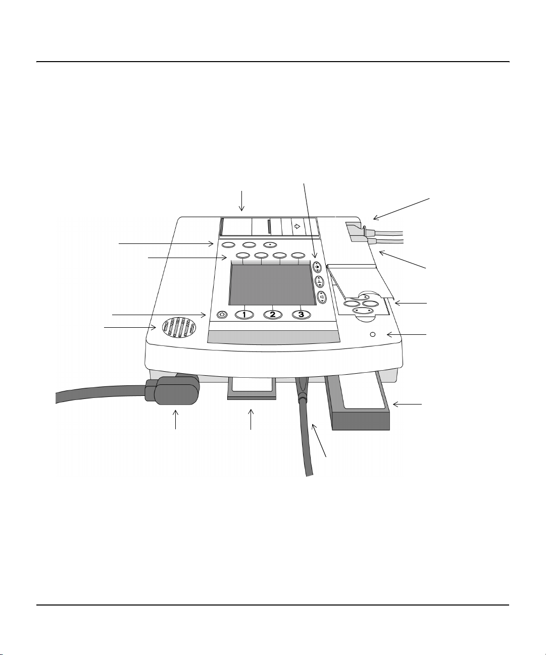
Figure 2-1 Basic Orientation
Print Controls
Monitoring Controls
Defibrillation
Controls
Speaker
Basic Orientation
The figure below shows the general layout of the controls, where the patient
cables connect, and where to insert the battery and Data Card.
Audiovisual
Off
Printer
On
Controls
ECG
Connector
SpO
Connector
Manual Mode
Controls
Ambient Light
Sensor
2
Battery
Pads
Connector
2-2 Getting Started
Data Card
AC Power
Module Connector
Page 23
Getting Acquainted
Print
Summary
Print
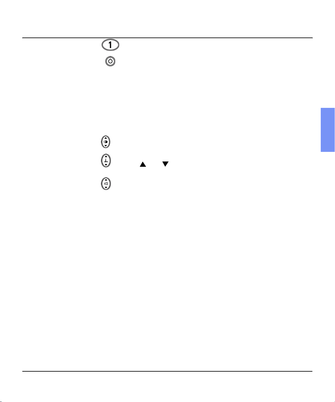
- Powers on the HeartStart XLT.
- Powers off the H eartStart XLT.
Defibrillation Controls - softkeys that perform the defibrillation function
displayed in the softkey label above each button; control both AED and Manual Mode defibrillation.
Manual Mode Controls - provi de access to Manual Mode and cont rol of synchronized cardioversion and pacing (if the option is present).
Audiovisual Controls:
Adjusts the display contrast.
Adjusts the size of the ECG waveform displayed, printed, and stored.
Pressing and simultaneously generates a 1 mV calibration pulse.
Adjusts the volume of voice prompts and the QRS beeper.
Monitoring Controls - softkeys that perform the monitoring function displayed in the softkey label below each button; control heart rate and SpO
2
alarms and select the ECG source to monitor.
Print Controls - perform the function shown above each button. The print
controls from left to ri ght are:
Print
Strip
Prints ECG data, defibrillation events, and marked events realtime or with a 6 second delay (as configured). Press to start printing; press again to stop printing.
Print
Summary
Prints the Event Summary. (See “Storing, Retrieving & Printing”
for more information.) Printing ma y be stopped by pressing the
or button.
Strip
2
Mark
Event
M3500B HeartStart XLT Defibrillator/Monitor 2-3
Inserts a time-stamped annotation in the Event Summary. May be
configured to print an annotated ECG strip when pressed.
Page 24
Getting Acquainted
Manual Mode Controls
The figure below shows the Manual Mode controls. These controls are
accessed by lifting the door labeled "Manual."
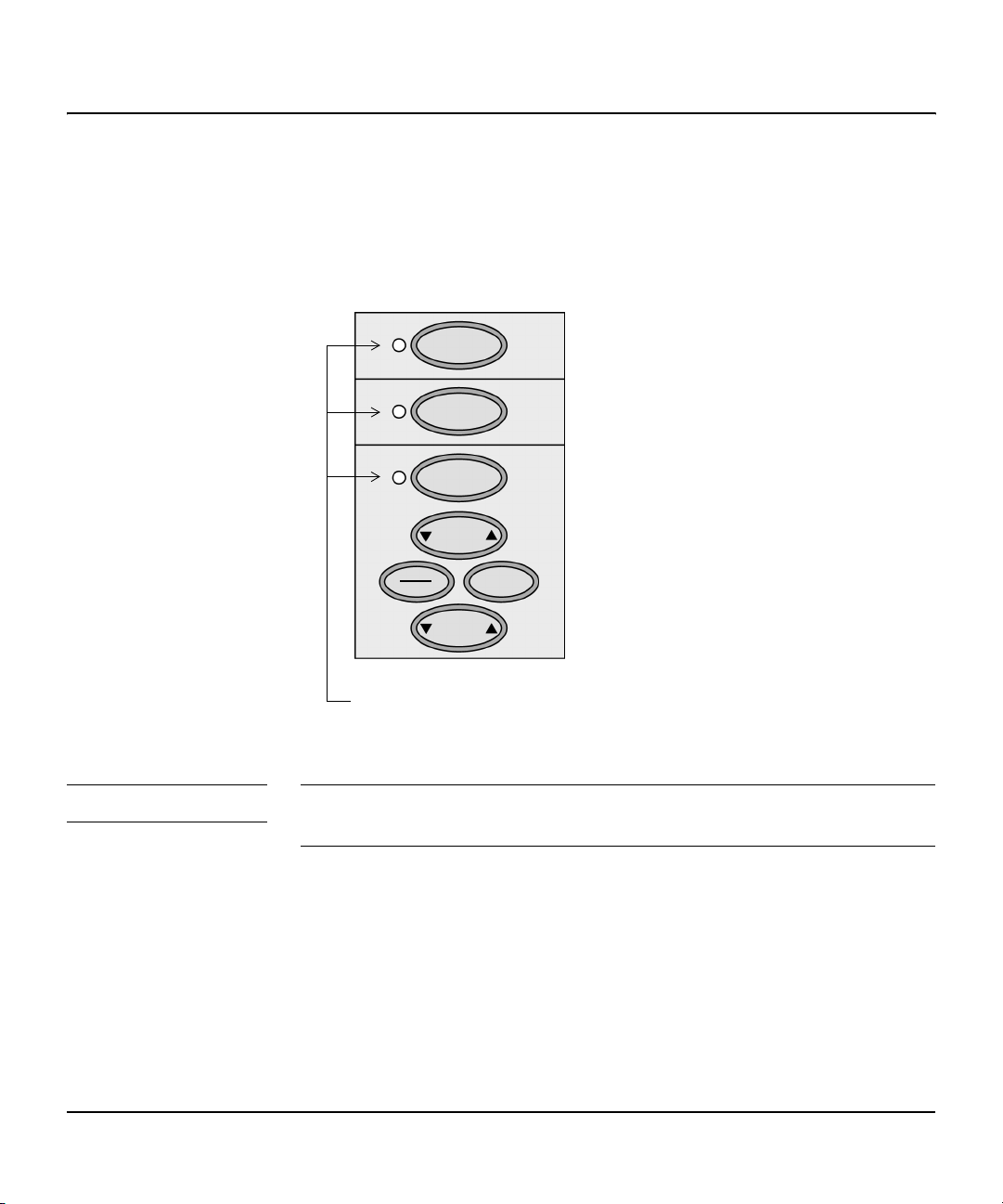
Figure 2-2 Manual Mode Controls
Manual
Sync
Pacer
Rate
Start
Stop
LEDs indicating the function is
active (green light) or inacti ve ( no light)
Mode
Output
NOTE Synchronized cardioversion and pacing controls only function when Manual
Mode is enabled.
2-4 Getting Started
Page 25

Getting Acquainted
Manual
Sync
Pacer
Toggles between Manual Mode and AED Mode. Manual
Mode is enabled whe n the gr een LED next to the key i s li t.
A password may be required for Manual Mode entry.
Enables synchronized cardioversion when first pressed, as
indicated by the green LED; disables synchronized cardioversion when press ed again.
Activates the pacing function buttons (as indicated by the
green LED), allowing you to use the buttons below to
define pacing rate, mode, and curr ent output. Also turns off
the Pacer when pressed a second time.
2
Display Layout
The following figures show the layout of the display in:
z
AED Mode, with ECG and SpO2 monitoring capabilities disabled.
z
AED Mode, with ECG and SpO2 monitoring capabiliti es enabled.
z
Manual Mode.
NOTE ECG and SpO
disabled independently in the conf ig uration.
Rate
Start
Stop
Mode
Output
monitoring capabilities for AED Mode may be enabled and
2
Adjusts the pacing rate.
Delivers pacer pulses when first pressed;
stops pacing when pressed again.
Selects Demand or Fixed Mode for pacing.
Adjusts the current output for pacing.
M3500B HeartStart XLT Defibrillator/Monitor 2-5
Page 26
Getting Acquainted
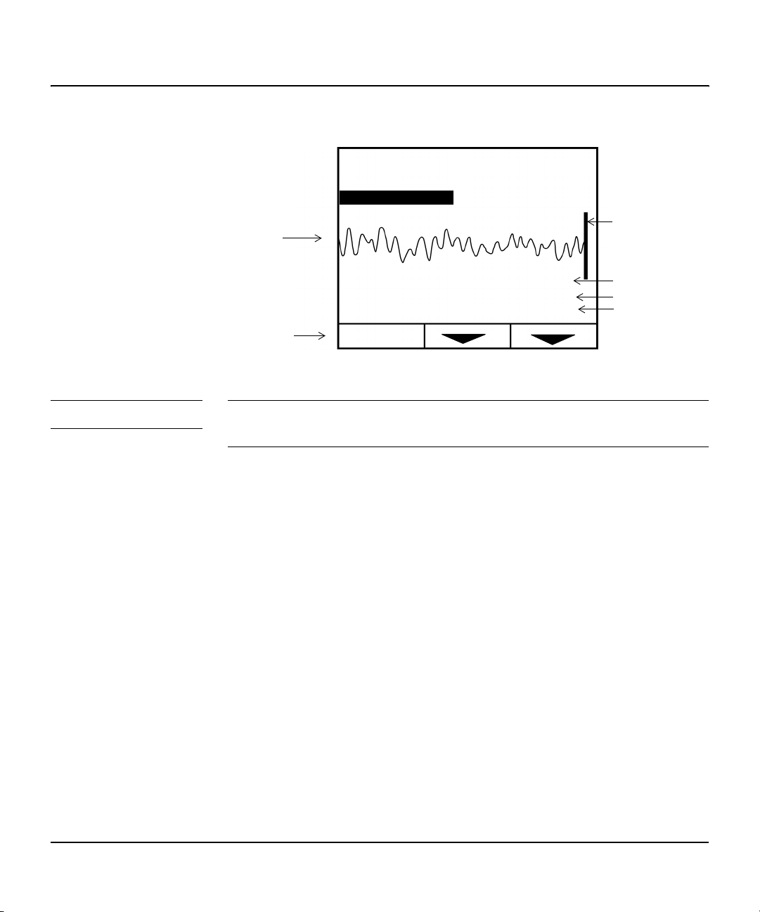
Figure 2-3 AED Mode Display Layout (ECG and SpO2 disabled)
System Message
Momentary Message
ECG
ECG Gain
Defibrillation
Soft Keys
PAUSE
User Message
ANALYZE
150J
Shocks: 0
00:15:02
SHOCK
Current Charge
Shocks Delivered
Incident Timer
NOTE In its default configuration, the HeartStart XLT powers on in AED Mode
where voice prompts and user messages are active.
The Incide nt Timer shows the elapsed time since the HeartStart XLT was
turned on. If the HeartStart XLT is powered on after being off for less than
two minutes, the Incident Timer resumes where it left off. If power is off fo r
more than two minutes, the Incident Timer resets to zero (
).
2-6 Getting Started
Page 27
Getting Acquainted
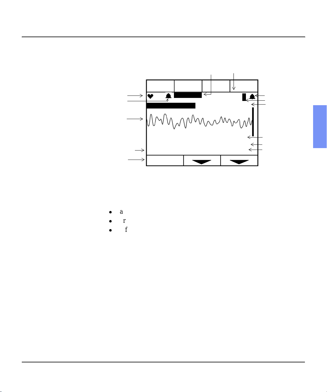
Figure 2-4 AED Mode Display Layout (ECG and SpO2 Enabled)
Lead
Displayed
SpO
value
2
LEAD
SELECT
Lead II
User Message
ANALYZE SHOCK
SPO2
86
PR 130
114J
Shocks: 0
00:15:02
SpO
alarm
2
Pleth Bar
Pulse Rate
Current Charge
Shocks Delivered
Incident Timer
Heart Rate
HR Alarm
ECG
Selected En ergy
Defibrillation
Soft Keys
HR ALARM
132
System Message
Momentary Message
150J
PAUSE
User messages accompany voice prompts to guide you through the defibrillation process.
System and Momentary Messages:
z
alert you to conditions that may require you to take action,
z
provide status information, or
z
offer recommendations.
A System Message remains on the display until the condition that generated
the message no longer exists. A Momentary Message is temporary and
appears on the display for only a few seconds. A list of messages is provided
in Chapter 12.
2
M3500B HeartStart XLT Defibrillator/Monitor 2-7
Page 28
Getting Acquainted
S
C
S
I
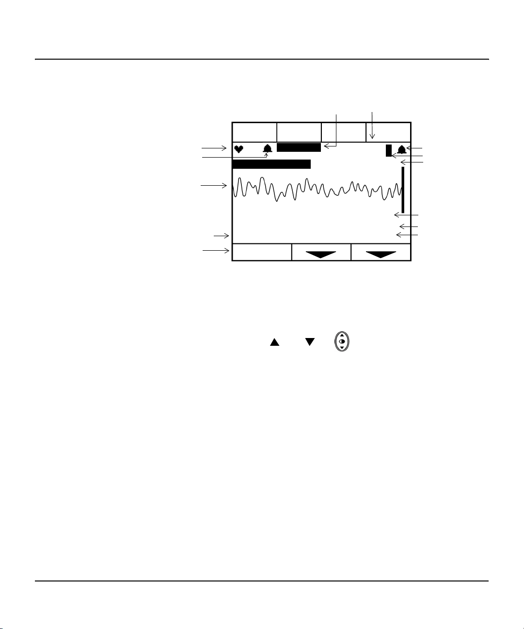
Figure 2-5 Manual Mode Display Layout
Displayed
Lead
SpO
value
2
LEAD
SELECT
Lead II
CHARGE SHOCK
SPO2
86
PR 130
114J
Shocks: 0
00:15:02
SpO
alarm
2
Pleth Bar
Pulse Rate
urrent Charge
hocks Delivered
ncident Timer
Heart Rate
HR Alarm
ECG
elected Energy
Defibrillation
Softkeys
HR ALARM
132
System Message
Momentary Message
150J
ENERGY
SELECT
LCD Backlight
Under normal operation, the HeartStart XLT reads the ambient light and turns
on the LCD back light when low light conditions exist. To turn on the back
light at other times, press and on simultaneously. To return to
normal operation, press the same keys again. The back light also returns to
normal operation each time you turn the HeartStart XLT on.
2-8 Getting Started
Page 29
Connecting to Power
Connecting to Power
The HeartStart XLT is powered by the M3516A batte ry. Prior to inser ti ng the
battery, make sure that the battery is charged and has been properly maintained (See “Bat tery M aintenan ce” on pa ge 1 1 -8). A fu lly char g ed batte ry will
last for about t wo hours. A second spare ch arged battery should be kept in the
carrying case at all times.
The HeartStart XLT can also be powered by the M3517A AC Power Module
or the M3518A DC Power Module . However the d efi brilla tor will t ake longer
to charge when powered by a power module, with the battery absent. The recommended practice when using a power module is to use the module in conjunction with a battery. For information on using the power modules, see the
documentation supplied with the modules.
NOTE To save battery capacity, the HeartStart XLT shuts itself off if a patient is not
being monitored and no one has interacted with the device for 10 minutes.
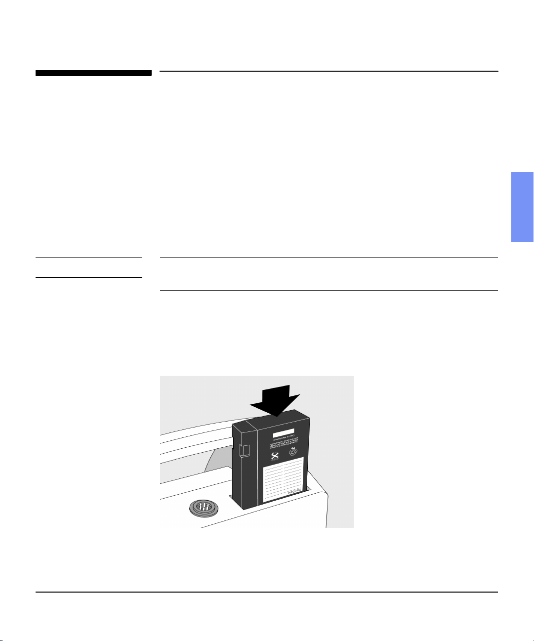
Inserting the Battery
2
T o inse rt th e batte ry, slide it into th e batt ery rec eptacle as shown i n Figure 2-6.
Then push the battery in until you hear an audible click.
Figure 2-6 Inserting the Battery
M3500B HeartStart XLT Defibrillator/Monitor 2-9
Page 30

Connecting to Power
Removing the Battery
Before remo ving the battery, make sure the HeartStart XLT is powered off.
Then, to remove the battery, press the black battery eject button and pull the
battery out, as shown in Figure 2-7.
Figure 2-7 Removing the Battery
Low Battery Warning
The message /RZ%DWWHU\ is displayed on the HeartStart XLT when the battery
is low and needs recharging. This message indicates that the battery has sufficient remaining capa city to pro vide only about t en minutes of monitoring time
and six shocks before the HeartStart XLT shuts off. Replace the battery as
soon as possible.
If the power is off for less than 2 minutes, while you change the battery, the
HeartStart XLT assumes that you a re continuing to treat the s ame patient. It
continues to store data on the Data Card and append events to the existing
Event Summary. Alarms set prior to the power loss remain active.
If power remains off for more than 2 minutes, the HeartStart XLT assumes
you are treating a dif f erent patie nt and as signs a new inci dent numbe r. A new
Event Summary begins w ith the next event.
2-10 Getting Started
Page 31

Using a Data Card
Using a Data Card
Use of a Data Card is optional; the defibrillator will power up without a Data
Card inserted. If you would like to collect patient information on a Data Card,
the card must be inserted into the HeartStart XLT before the device is turned
on.
CAUTI ON Inserting or removing the data card while the defibrillator is on can corrupt
the Data Card and prevent th e unit f rom poweri ng on agai n. If thi s occur s, see
Table 12-3, Troubleshooting Tips.
The recommended practice is to use one Data Card per patient. Once a Data
Card fills, recording st ops; a second Data Card may not be inserted for the
current incident, because the device will only allow the use of one Data Card
per incident. Data Cards hold up to two hours of patient information.
Multiple incidents can be recorded on a single Data Card. Each incident is
assigned a unique incident number.
Patient data from a Philips M3510A Data Card may be downloaded to a
HeartStart Event Review Data Management system. HeartStart Event Review
also allows you to erase pati ent data fr om a Data Card , allowing the card to be
reused for another patient.
2
It’s recommended that you use a designated Data Card to configure one or
more defibrillators/monitors.
CAUTI ON Use only the M3510A Data Card. These cards are specifically formatted to
work with your Philips defibrillator. Generic cards, or other types of cards
(such as modems) will not work, and may cause the defibrillator to
malfunction.
M3500B HeartStart XLT Defibrillator/Monitor 2-11
Page 32

Using a Data Card
Inserting a Data Card
To insert a Data Card:
1. Make sure the HeartStart XLT is powered off.
2. Press up on the release latch to open the door to the Data Card compartment.
3. If a Data Card is al ready in the compa rtment, press the b lack b utton ins ide
the compartment to ejec t the card (see Figure 2-8). Then pull t he ca rd out .
4. With the yellow label facing up and the pointing towards the HeartStart XLT, slide the Data Card into the comp artment.
5. Close the Data Card compartment door. Make sure that you hear a click,
indicating that the door is latched shut.
Figure 2-8 Inserting a Data Card
Eject
2-12 Getting Started
Page 33

Using a Data Card
Removing a Data Card
To remov e the Data Ca rd:
1. Make sure the HeartStart XLT is powered off, (wait 2 seconds).
2. Press the black eject button (see Figure 2-8).
3. Pull the Data Card from the compartment.
2
M3500B HeartStart XLT Defibrillator/Monitor 2-13
Page 34

Page 35

3 Defibrillating in AED Mode
The HeartStart XLT’s AED Mode is designed to guide you through standard
treatment algori thms for c ardia c arr est, i ncludi ng tho se p rovide d by th e Amer ican Heart Association and the European Resuscitation Council. Configuration choices allow you to customiz e AED Mode to better follow a specif ic
treatment algorithm and to meet the unique needs of your life-saving team.
This chapter describes how to use the H eartStart XLT to defibrillate in AED
Mode. It explains the prompts that guide you through the defibrillation process and describes how prompts vary depending upon the condition of the
patient and the configuration of your device.
For information on printing, storing, and retrieving patient information
acquired in AED Mode, see Chapter 9.
3
M3500B HeartStart XLT Defibrillator/Monitor 3-1
Page 36

Figure 3-1 AED Mode Overview
If Patient is:
z
Unresponsive
z
Not Breathing
z
Pulseless
Attach Pads
Insert Data Card
(Optional)
Press On
If Instructed,
Press
$1$/<=(
No Shock
Check Patient
No Pulse
3$86(
Advised
Pulse
Ventilate
Advised
Press
within a shock series
Shock
6+2&.
at completion of shock series
Press
Do CPR
if Rhythm Monitoring on
3-2 Defibrillating in AED Mode
Page 37

Overview
Overview
An overview of the AED Mode defibrillation process is shown in Figure 3-1.
The process begins only after you have:
z
assessed that the pati ent is unres ponsive, not breathing , and pulseles s,
and
z
prepared for defibrillation by attaching pads and inserting a Data
Card (if desired).
Then you are ready to turn the HeartStart XLT on. The defibrillation process
is dependent upon the configuration of your HeartStart XLT, as described in
the following paragraphs.
Defibrillation (with the defa ult configuration)
In its default configuration, the defibrillation process is:
Press the On button.
The HeartStart XLT checks to see if the pa ds patient cable and multifunction defib electrode pads are properly connected. If either connection is compromised, you are prompted to fix the problem.
Analysis begins automatically - there is no need to press
$1$/<=(
.
Once analysis is complete, the HeartStart XLT tells you 6KRFN$GYLVHG
or 1R6KRFN$GYLVHG.
If a shock is advised, press .
6+2&.
After the first shock is delivered, the HeartStart XLT automatically
begins analyzing the ECG a nd the p rocess re peats until a shock serie s
is complete or no s hoc k i s advised. At this point, you ar e p rompt ed to
check the patient.
3
M3500B HeartStart XLT Defibrillator/Monitor 3-3
Page 38

Overview
Defibrillation (with a modified configuration)
Chapter 10 describes, in detail, th e configurable parameters for AED Mode.
Three parameters signif icantly impact the defibrillation process. They are:
Device Initiated Analysis - initia tes ECG analy sis when the He artStart XLT
is first turn ed on. The default configuration setting is
this paramet er to 2II, you need to press to initiate analysis in step 2
$1$/<=(
of the defibrillation process.
Automatic Re-analysis - initiates ECG analysis in between shocks within a
shock series. The default configuration setting is 2Q. If you choose to set this
parameter to 2II, you need to press
$1$/<=(
to initiate a nalysis in between
shocks within a shock series (i.e. after the first and second shock of a three
shock seri es).
Rhythm Monitoring - monitors the ECG for potentially shockable rhythms
when the HeartStart XLT is not analyzing, defibrillating, or paused. The
default setting is 2QIf you choose to set this parameter to 2II, the HeartStart
XLT will not look for potentially shockable rhythms during these idle times.
Idle times also include:
z
power on, when Device Initiated Analysis is off.
z
in between shocks within a shock series, when Auto Re-analysis is
off.
On. If you choose to set
If Rhythm Monitoring is of f, you need to obser ve the patie nt during idl e times
and determine when to press
$1$/<=(
.
The following sections describe the defibrillation process in detail. They also
describe what happens at the completion of a shock series and if a shockable
rhythm is not detected.
3-4 Defibrillating in AED Mode
Page 39

Preparation
Preparation
If the patient is:
z
unresponsive
z
not breathing
z
pulseless
Then:
1. Apply multifunction def ib el ectro de p ads to t he pat ient, a s dir ected o n the
package. Use the anterior-anterior electrode placement.
2. Connect the pads to the pads patient cable, as shown in Figure 3-2.
3. If needed, insert a Data Card (as described in “Using a Data Card” on 2-
11).
Figure 3-2 Connecting Pads to the Patient Cable
3
M3500B HeartStart XLT Defibrillator/Monitor 3-5
Page 40

Defibrillating
Defibrillating
Follow the voice and screen prompts as they guide you thro ugh t he f ollowing
steps:
1. Press On.
In this first st ep of the defibrillation process, the HeartStar t XLT checks to
see if the pads patient cable and the pads are connected. If they are, it proceeds to step 2.
If the pads patient cable is not properly attached, you are prompted to &RQ
QHFW3DGV&DEOH.
Figure 3-3 Connect Pads Cable Display
Connect
Pads
Cable
Shocks: 0
00:00:02
Once the cable is connected, the HeartStart XLT checks to make sure the
pads are making good contact with the patient’s skin. It does this by monitoring the electrical impedance between the two pads.
3-6 Defibrillating in AED Mode
Page 41

Defibrillating
If the pads have not been applied or are not making proper contact with the
patient, you are prompted to $SSO\3DGV and &KHFN&RQQHFWLRQV.
Figure 3-4 Apply Pads Display
Apply
Pads
Shocks: 0
00:00:03
3
M3500B HeartStart XLT Defibrillator/Monitor 3-7
Page 42

Defibrillating
2. If instructed, press .
$1$/<=(
If device-initiated analysis is off, the HeartStart XLT monitors the rhythm
(provided Rhythm Monitoring is on) and prompts you to press
$1$/<=(
a potentially shockable rhythm is detected.
Figure 3-5 Press ANALYZE Display
Check Patient
If No Pulse
PAUSE
Press ANALYZE
ANALYZE
Shocks: 0
00:00:04
NOTE If monitoring capabilities are enabled on your HeartStart XLT, your display
will contain monitori ng i nf ormat ion not shown in the graphics in thi s s ect ion.
if
NOTE ECG Analysis is always performed through multifunction defib electrode
pads. Analysis can not be performed through monitoring electrodes.
3-8 Defibrillating in AED Mode
Page 43

Defibrillating
If device initiated analysis is on, you do not need to press ; ECG
$1$/<=(
analysis begins automatically.
Figure 3-6 Analyzing Display
Analyzing
Do Not Touch Patient
Shocks: 0
00:00:08
STOP
ANALYSIS
WA RN I N G Handling or transporting the patient during ECG analysis can cause incorrect or
delayed diagnosis.
If a shockable rhythm is detected, as indicated by the message 6KRFN$GYLVHG,
analysis stops and t he XLT automatically charges to 150 J. Ch arging is accompanied by an intermittent charge tone.
3
Figure 3-7 Charging Display
Charging to 150J
97J
Shocks: 0
00:00:10
M3500B HeartStart XLT Defibrillator/Monitor 3-9
Page 44

Defibrillating
3. If shock advised, press .
6+2&.
Once charging is complete, the charge tone becomes continuous. Make
sure no one is touching the patient or anything connected to the patient.
Call out "Clear." Then press to deliver a shock to the patie nt.
Figure 3-8 Press SHOCK Display
Stand Clear!
Press SHOCK
WA RN I N G Defibrillation current can cause operator or bystander injury. Do not touch the
6+2&.
150J
Shocks: 0
00:00:14
SHOCK
patient, or equipment connected to the patient, during defibrillation.
The defibrillator automatically disarms if you do not press in 30
6+2&.
seconds.
3-10 Defibrillating in AED Mode
Page 45

Defibrillating
Delivery of the shock is confirmed by the message 6KRFN'HOLYHUHG and the
shock counter is updated.
Figure 3-9 Shock Delivered Display
Shock Delivered
Shocks: 1
00:00:40
Automatic Re-analysis On
If Automatic Re-analysis is on, the HeartStart XLT analyzes the ECG following delivery of the shock. You are prompted to press , if an a ddi-
tional shock is advised. This cycle repeats until the rhythm converts or a
shock series is complete. (A shock series may be configured to 2, 3, or 4
shocks.)
6+2&.
3
Automatic Re-analysis Off
If Automatic Re-analysis is off, the HeartStart XLT monitors the ECG for
potentially shockable rhythms (provided Rhythm Monitoring is on) and
prompts you to press if one is detected. You can initiate analysis,
without being prompted, by pressing .
M3500B HeartStart XLT Defibrillator/Monitor 3-11
$1$/<=(
$1$/<=(
Page 46

Pausing for CPR
Pausing for CPR
At the completion of a shock series or when no shock is advised, the HeartStart XLT prompts y ou to &KHFN3DWLHQW&KHFN3XOVH. It allows eight seconds for
you to check the pulse, then prompts you as follows:
Figure 3-10 Press Pause Display
If Needed
Press PAUSE
PAUSE
And Begin CPR
ANALYZE
Shocks: 1
00:00:50
If CPR is nee ded, press . While paused, the Pau se Timer indicates th e
3$86(
elapsed time and the total duration of the Pause state, in seconds. The Pause
Timer is configurable to meet your local CPR protocol needs. Rhythm, SpO
2
and heart rate monitoring alarms are suspended for the duration of the pause.
NOTE * This section describes how the Pause state functions using the default con-
figuration. If your HeartStart XLT is configured to support the European
Resuscitation Council G uidelines fo r Resuscitat ion, refer to the “ERC Protocol” section on page 3-16 for details.
3-12 Defibrillating in AED Mode
Page 47

Figure 3-11 Pause Display
Pausing for CPR
RESUME
Paused
Timer: 21 / 60
ANALYZE
Shocks: 3
00:01:40
Elapse Time
Total Pause Duration
The pause state ends when the Pause Timer reaches the preconfigured Pause
state duration, or if you press or . At the completion of the
5(680(
$1$/<=(
pause state, the defibrillation process begins again. If instructed, press
$1$/<=(
If you do not press , the HeartStart XLT begins monitoring the ECG
.
3$86(
rhythm (provided Rhythm Monitoring is on).
You may initia te ECG analysis at any time by pressing
$1$/<=(
.
3
M3500B HeartStart XLT Defibrillator/Monitor 3-13
Page 48

Monitoring Rhythm
Monitoring Rhythm
When the HeartStart XLT is not analyzing, defibrillating, or paused, Rhythm
Monitoring alerts you to potentially shockable rhythms (provided Rhythm
Monitoring is set to the default configuration, 2Q). The message 0RQLWRULQJ
5K\WKP appears on the display to let you know this feature is active and
remains on the display for the duration of the m onitoring.
Figure 3-12 Monitoring Rhythm Display
Monitoring Rhythm
Shocks: 3
00:00:49
PAUSE
ANALYZE
WA RN I N G The recommended configuration setting for Rhythm Monitoring is On. If Rhythm
Monitoring is off, you are not alerted when a patient’s rhythm changes from nonshockable to shockable (as in refibrillation or an initially nonshockable rhythm that
converts to a shockable rhythm).
3-14 Defibrillating in AED Mode
Page 49

Monitoring Rhythm
3$86(
If Rhythm Monitoring detects a shockable rhythm, you are prompted as follows:
Figure 3-13 Shockable Rhythm
Check Patient
If No Pulse
PAUSE
Press ANALYZE
ANALYZE
Shocks: 3
00:00:55
This prompt is rep eated per iodicall y, as configure d, until or is
pressed. If you press , the defibrillation process starts again.
If you press
pause. is used when administering CPR, as not ed earl ier. It may also be
3$86(
$1$/<=(
, rhythm monitoring is suspended for the duration of the
$1$/<=(
3$86(
useful when performing medical procedures or encountering artifact during
patient transport. Act ive SpO
and heart rate alarms are suspended during the
2
pause duration, as well.
5(680(
Press
to restore rhyth m mon it ori ng. Acti ve SpO
and heart rate alarms
2
are also restored.
3
M3500B HeartStart XLT Defibrillator/Monitor 3-15
Page 50

ERC Protocol
ERC Protocol
The HeartStart XLT can be configured to support the European Resuscitation
Council (ERC) Guidelines for Resuscitation (1998). If (XURSHDQ3URWRFRl is configured to 2Q, the defibrillation process described in this chapter is the same,
with the exception of how the Pause state functions (see “Pausing for CPR”
on 3-12).
As described, you can enter a Pause state:
z
at the completion of a shock series, or
z
when no shock is advised
When either of these events occurs, the ERC protocol prompts you to Check
Patient. Then it prompts you as follows:
Figure 3-14
If Needed
Press PAUSE
And Begin CPR
PAUSE
NOTE Using the ERC protocol, you are not prompte d to (or given time to) che ck the
ANALYZE
Shocks: 1
00:00:50
patient’s pulse.
3-16 Defibrillating in AED Mode
Page 51

ERC Protocol
If CPR is needed, press . While paused, a timer indicates the elapsed
3$86(
time and the total duration of the Pause state, as shown:
Figure 3-15
RESUME
Paused
Timer: 35 / 60
ANALYZE
Shocks: 3
00:01:40
Elapsed Time
Total Pause Duration
The total pause duration depends on the event preceding the Pause state. If
you entered the Pause state:
z
at the completion of a shock series or shortly after a shock is delivered, the duratio n is eq ual to the 3RVW6KRFN&357LPHU configuration set-
ting (the default setting is 60 seconds).
z
when no shock was advised, the duration is equal to the 16$7LPHU
configuration setting, where NSA is an acronym for No Shock
Advised (the default setting is 180 seconds).
3
M3500B HeartStart XLT Defibrillator/Monitor 3-17
Page 52

Troubleshooting
Troubleshooting
When the HeartStart XLT detects a problem, it provides display and/or voice
prompts to guide you to r esoluti on. The tabl e below lists the prompts you may
encounter in AED Mode, the cause, and the suggested corrective action.
Prompts related to the battery and Data Card are discussed in Chapter 12.
Table 3-1 AED Mode Prompts
Prompt Possible Cause Corrective Action
Pads Off The multifunction def ib electrode
pads are not properly applied to the
patient.
Pads Cable
Off
Artifact
Detected
The pads cable is not conn ected to
the defibrillator.
z
Patient motion interferes with
analysis.
z
Electrical sources are causing
interference.
Shock Cancelled
No Shock
Delivered
Key
Inactive
Shock key not pressed within 30
seconds.
Pads are not properly connected to
the patient.
z
The key pressed only functions
in Manual Mode.
z
The key pressed does not function during anal ys is or ch arging.
z
The key pressed does not function while in a pause state.
Check that th e pa ds are applied to
the patient, as directed on the pads’
package. Replace the pads if the
prompt continues.
Check that the defibrillation pads
connector is locked in place.
z
Attempt to eliminate patient
motion. Avoid analyzing
during transpor t or while
performing CPR.
z
Move hand-held communication
devices or other suspected
devices away from the defibrillator, when possible.
Press within 30 seconds of prompt.
Check pads connection.
z
Access manual mode prior to
pressing the key.
z
W ait for analysis or charging to
complete prior to pressing the
key.
z
5(680(
Press prior to pressing
the key.
3-18 Defibrillating in AED Mode
Page 53

4 Monitoring the ECG
The HeartStart XLT can be used for short or long-term ECG monitoring. The
ECG monitoring function allows you to monitor through:
z
multifunction defib electrode pads, or
z
3- or 5-lead ECG monitoring electrodes, as configured.
When the HeartStart XLT is turned on, the ECG acquired through pads is
shown on the display. ECG monitoring allows you to continue to monitor
through the pads or to select a lead from an alternate ECG source (3- or 5lead). ECG monitoring al so displays the heart rat e ( HR) a nd allows you to set
HR alarms.
ECG monitoring is always act iv e in Manual Mode. In AED Mode, ECG monitoring is o nly active if /HDG6HOHFWis configured to on (the default is off).
A fully charged battery provides approximately 2.7 hours of continuous monitoring.
This chapter describes how to apply monitoring electrodes, select the lead to
monitor, and set a heart rate (HR) alarm. To apply multifunction defib electrode pads, follow the directions on the pads packaging. For information on
printing, storing, and retrieving patient information acquired while monitoring, see Chapter 9.
NOTE If you need to connect the ECG cable to the HeartStart XLT or configure the
HeartStart XLT to use the optional 5-lead monitoring cable, see Chapter 10.
M3500B HeartStart XLT Defibrillator/Monitor 4-1
4
Page 54

Applying Monitoring Electrodes
Applying Monitoring Electrodes
Proper application and placement of electrodes is essential for reliable monitoring. Good contact betwee n the elect rode and the skin reduce s the eff ects of
motion artifact and signal interference.
To apply electrodes:
1. Identify the appropriate electrode sites. (See Figure 4-1.)
2. Shave the electrode sites or clip hair, if necessary.
3. Clean and abrade the skin at the electrode sites.
4. Dry the skin at the electrode sites.
5. Open a new package of M2202A Radio-Translucent Monitoring Electrodes; ver ify that the " Use Before" date has not passed.
6. Snap the lead wires onto the electrodes.
7. Apply the electrodes by peeling them, one at a time, from the protective
backing and sticking them firmly to the patient’s skin. Press around the
entire edge of each elect rode to ensure tha t they are secure. Make sure the
lead wires do not pull on the electrodes.
WA RN I N G Be sure that the electrodes do not come in contact with other conductive materials,
especially when connecting or disconnecting the electrodes to/from the patient.
NOTE If monitoring for long periods of time, new monitoring electrodes and
multifunction defib el ectrode pads may need to be applied peri odi cally. Refe r
to the manufacturer’s documentation for how often to replace the monitoring
electrodes or defib pads.
4-2 Monitoring the ECG
Page 55

Applying Monitoring Electrodes
Electrode Placement
Figure 4-1 shows typical electrode placement for the limb leads of a 3- or 5lead patient cabl e. The V/ C lead of the 5- lead ca ble can be place d in any of the
precordial lead positions (V1/C1 through V6/C6) shown in Figure 4-2.
Figure 4-1 Limb Lead Electrode Placement
AHA Labels IEC Labels
RA/R LA/L
RA Right Arm R Right
LA Left Arm L Left
RL Right Leg* N Negative*
*
RL/N LL/F
Table 4-1 3-Lead ECG Lead Formation
Lead + - Reference
I
II
III
LA RA LL
LL RA LA
LL LA RA
LL Left Leg
* Not used for 3-lead.
F Foot
4
M3500B HeartStart XLT Defibrillator/Monitor 4-3
Page 56

Applying Monitoring Electrodes
LA + LL
RA + LA
RA + LL
RA + LA + LL
Figure 4-2 Precordial Lead Electrode Placement
Electrode Location
V1 C1 forth intercostal spac e, at righ t sternal
V2 C2 forth intercostal space, at left sternal
1
2
3
5
4
6
V3 C3 midway between V2/C2 and V4/C4
V4 C4 fifth intercostal space, at left midclav-
V5 C5 same level as V4/C4, on anterior axil-
V6 C6 same level as V4/C4, at left mid axil-
Table 4-2 5-Lead ECG Lead Formation
margin
margin
icular line
lary line
lary line
Lead Lead Formation
ILA - RA
II LL - RA
III LL - LA
aVR
aVF
aVL
V
(or Cx)
x
where x = 1-6
RA -
LL -
LA -
V/C -
2
2
2
3
4-4 Monitoring the ECG
Page 57

Selecting the Lead
Selecting the Lead
Available monitoring leads are dependent upon your device configuration:
Table 4-3 Lead Select Choices
Lead Select
Choices are:
Pads, Lead I, Lead II, Lead III 3-lead ECG cable
Pads, Lead I, Lead II, Lead III, aVR,
aVL, aVF, V lead.
5-lead ECG cable
To select a lead to mon it or, cycle thr ough t he choices by pressing until
If Configured for a:
6(/(&7
/($'
the desired lead is displayed.
NOTE When V lead is selec ted, ch ange t o a dif fer ent V lea d by moving t he ele ctrod e
to a new location rather than by pressing the softkey.
Figure 4-3 ECG Monitoring Display
HR ALARM
78
LEAD
SELECT
Lead II
Monitoring Rhythm
/($'
6(/(&7
4
Shocks: 3
00:00:49
PAUSE
ANALYZE
If the desired lead is not connected or the electrodes are not making proper
contact with the patient, the message /HDGV2II is displayed in the System Message Area and accompanied by a beep to alert you. A dashed line on the display indicates that there is no ECG signal.
M3500B HeartStart XLT Defibrillator/Monitor 4-5
Page 58

Setting the Heart Rate Alarm
Setting the Heart Rate Alarm
The computed heart rate (number of detected QRS complexes per minute) is
displayed below the sofkey, next to the . The heart rate represents
the number of QRS complexes detected in a minu te . A QRS beeper, if configured to on, indicates each QRS complex detected.
If desired, a HR alarm may be set to alert you when the heart rate is outside
the specified limits. Limit choices are listed in Table 4-4.
Table 4-4 HR Alarm Limit Choices
Alarm If Over: Or under:
+5$/$50
100 30
140 60
160 90
200 120
To set a HR alarm, cycle through the limit choices by pressing until
+5$/$50
the desired limits are shown. The then appears next to the heart rate value
to indicate that the HR alarm is set.
WA RN I N G Heart rate alarms are temporarily suspended in AED Mode during ECG analysis or
3$86(
when is pressed (for the duration of the paused period). Heart rate alarms are
also suspended while charging for defibrillation and delivering a shock.
WA RN I N G Heart rate displays and alarms function with internal and external pacemakers, but
they can be unreliable. Observe the patient closely if pacemakers are used.
4-6 Monitoring the ECG
Page 59

Disabling the HR Alarm
Disabling the HR Alarm
If the heart rate is outside th e HR alarm limits, an alarm sounds. To disable the
alarm, press . appears to indicate that the alarm is disabled.
+5$/$50
Adjusting the ECG Size
To increase or decrease the size of the ECG, press or on the gain control, .
Troubleshooting
Table 4-5 provides troubleshooting tips for ECG Monitoring.
Table 4-5 Troubleshooting Tips
Situation Cause Solution
z
/HDGV2IImessage
or
dashed line (------)
The monitoring electrodes are not applied
or are not making
proper contact with the
patient.
z
The monitoring cable is
not connected.
z
Check that the monitoring
electrodes are properly
applied.
z
Check that the monitoring
cable is properly connected.
4
z
3DGV2IImessage
M3500B HeartStart XLT Defibrillator/Monitor 4-7
The pads are not making proper contact with
the patient.
z
Check that the pads are
properly applied.
Page 60

Troubleshooting
Table 4-5 Troubleshooting Tips (Continued)
Situation Cause Solution
Poor ECG signal
quality
QRS beeper inaudible or beeps do
not occur with
each QRS complex.
z
The monitoring electrodes are not making
proper contact with the
patient.
z
The monitoring electrodes are outdated or
dried-out.
z
Radio frequency interference (RFI) is causing
artifact.
z
The QRS beeper is configured to Off.
z
The amplitude of the
QRS complex is too
small to detect.
z
Check that the monitoring
electrodes are properly
applied. If necessary, prepare the patient’ s sk in and
apply new electrodes.
z
Check the date code on
the electrodes. Do not
open the electrode package until immediately
prior to use.
z
Relocate or turn off equipment that may be causing
RFI.
z
Check that the QRS
beeper is configured to
On.
z
Adjust the volume.
z
Adjust the size of the
ECG.
4-8 Monitoring the ECG
Page 61

5 Monitoring SpO
Pulse oximetry is a noninvasive method of continuously measuring oxygen
saturation (SpO
percentage of hemoglobin molecules in the arterial blood which are saturated
with oxygen. SpO
ing a patient’s cardiac and respiratory systems. This chapter explains how
pulse oximetry works and des cribes ho w to use th e HeartS tart XLT to monitor
SpO
2.
SpO2 monitoring is always available in Manual Mode (if the option is purchased). In AED Mode, SpO
ured to 2Q.
For information on printing, storing, and retrieving patient information
acquired while monitoring, see Chapter 9.
2
) in arterial blood. The resultant SpO2 reading indicates the
2
monitoring is one of the tools available to assist in assess-
2
monitoring is only available if SpO2 is config-
2
WA RN I N G Do not rely solely on SpO
may be inaccurate in the presence of significant levels of carboxyhemoglobin or
methemoglobin, in patients with restricted blood flow to the extremities (such as
those in severe shock or hypothermia), or in the presence of excessive motion.
M3500B HeartStart XLT Defibrillator/Monitor 5-1
readings; assess the patient at all times. SpO2 readings
2
5
Page 62

Understanding Pulse Oximetry
Understanding Pulse Oximetry
A pulse oximetry s ens or se nds light through patient t is sue t o a r eceiver on the
other side of the sensor. As Figure 5-1 shows, light emitting diodes transmit
red and infrared light through peripheral areas of the body, such as a finger.
Figure 5-1 Pulse Oximetry Sensor
LED
Photodetector
A photodetector positioned opposite the light emitting diodes compares light
absorption before and after pulsation. The amount of light getting through
reflects the blood f lo w i n t he a rt er iol es . Thi s meas urement of light absorption
during pulsation is translated into an oxygen saturation percentage and an
SpO
value is displayed.
2
For accurate SpO
z
The patient must have perfusion in that extremity.
z
The light emitter an d the photodete ctor must be direct ly opposit e each
measurements, the following conditions must apply:
2
other.
z
All of the light from the emit te r must pas s throu gh t he pati ent’s tissue.
z
The sensor site should be free of vibration and excessive motion.
z
Power cables should be kept away from the sensor cable and connector.
5-2 Monitoring SpO
2
Page 63

Selecting a Sensor
Selecting a Sensor
Table 5-1 shows the SpO2 sensors that may be used with the HeartStart XLT.
Table 5-1 Approved Sensors
Sensor Type Patient Patient Size Ideal Site
M1191A Reusable Adult > 50 kg Finger
M1192A Reusable Small adult
Pediatric
M1194A Reusable Pediatric
Adult
M1903A/B
(Nellcor D-20)
M1904A/B
(Nellcor D-25)
M1906A
(Nellcor P/I)
M1907A
(Nellcor A/N)
NOTE To use Nellcor sensors, you must connect the M1943A Nellcor Adaptor
Disposable Pediatric 10-50 kg Toe/Finger
Disposable Ad ul t > 30 kg Finger
Semi-reusable
Semi-reusable
Pediatric
Infant
Neonate < 3 kg Foot/Hand
Adult > 40 kg Fin ger
patient cable to the HeartStart XLT. (See “Connecting the SpO
15-50 kg Finger
> 40 kg Fleshy part
of ear
3-40 kg Finger/Toe
Patient
2
Cable” on page 10-5.)
5
M3500B HeartStart XLT Defibrillator/Monitor 5-3
Page 64

Selecting a Sensor
The most important factor when selecting a sensor is the position of the light
emitting diodes in relation to the photodetector; when a sensor is applied, the
diodes and the photodetector must be opposite each other. Sensors are
designed for patients within a specific weight range and for specific sites. Be
sure to:
z
Select a sensor appropriate for the patient’s weight.
z
Select a sensor site with adequate perfusion.
z
Avoid application to sites with edematous tissue.
Reusable Sensors
Reusable sensors may be reused on different patients after they have been
cleaned and disinfect ed (see t he manu factu rer’ s instr uction s supp lied wi th the
sensor).
Disposable Sensors
Disposable sensors shou ld be use d only onc e an d then di scarded. The y can be
relocated to a different application site on the patient if the first location does
not give the desired results. Disposable sensors must not be reused on different patients.
Semi-disposable Sensors
Semi-disposable sensors can be reused, but the adhesive wrap must be discarded afte r each use. Semi-disposable sensors are recommended for singlepatient use only.
5-4 Monitoring SpO
2
Page 65

Applying the Sensor
Applying the Sensor
Follow the manufacturer’s directions for applying and using the sensor, making sure to observe any warnings or cautions. For the best results:
z
Make sure the sensor is dry.
z
If the patient is moving, secure the sensor cable loosely to the patient.
z
Avoid excessive pressure at the sensor sit e; ensure that circulation is
not obstructed.
z
Keep power cables away from the sensor cable and connection.
z
Avoid placing the sensor in an environment with bright lights (if necessary, cover the sensor with opaque material).
z
Avoid placing the sensor on any extremity with an arterial catheter,
blood pressure cuff, or intravascular venous infusion line.
WA RN I N G Failure to apply the sensor properly may reduce the accuracy of the SpO
measur-
2
ment.
WA RN I N G Inspect the sensor application site at least every two hours for changes in skin qual-
ity, correct optical alignment, and proper sensor application. If skin quality is compromised, change the sensor site. More frequent checking may be required due to an
individual patient’s condition.
5
M3500B HeartStart XLT Defibrillator/Monitor 5-5
Page 66

Connecting the Sensor Cable
Connecting the Sensor Cable
To connect a sensor cable:
1. Hold the connector with the flat side up so that the part number is visible.
2. Insert the connector into the receptacle and push until the blue portion of
the connector is no longer visible.
Figure 5-2 Connecting the Sensor Cable
5-6 Monitoring SpO
2
Page 67

Monitoring
To monitor SpO2:
1. If the HeartStart XLT is not on, press On.
2. Apply the appropriate sensor to the patient.
3. Make sure the sensor cable is connected to the HeartStart XLT.
4. Press to turn on SpO
6S2
monitoring.
2
Monitoring
A dashed line (---) is displayed under , while the oxygen saturation is
measured and an SpO
value is calculat ed. In a few se con ds the S pO2 value is
2
6S2
displayed in place of the dashed line. As the patient’s oxygen saturation
changes, the SpO
Figure 5-3 SpO2 Monitoring Display
HR ALARM
78
PAUSE
value is updated continuously.
2
LEAD
SELECT
Pads
Monitoring Rhythm
ANALYZE
SpO2
98
PR 62
Shocks: 3
00:00:49
To the ri ght of the SpO2 value, a pleth bar and SpO2 alarm indicator are displayed. The pleth bar should be observed for fluct uation. It is an indication of
pulsation detected by the sensor. The pleth bar should not be used as the sole
indicator of pulsation because it can be influenced by movement and artifact.
The symbol indicates no alarm is set.
5
Below the SpO
M3500B HeartStart XLT Defibrillator/Monitor 5-7
value is the pulse rate derived from the pulse oximetry.
2
Page 68

Setting Alarms
Setting Alarms
An alarm may be set to al ert you if the SpO2 value falls below a specified
lower limit. Lower li mit ala rm c hoi ces ar e (no alarm), 90, 85, o r 8 0. Pr es s
6S2
repeatedly to cycle th rough the choic es. Stop when the desired choi ce is
displayed. A appears in three seco nds, i ndicat ing t hat t he sel ected alar m is
active. To review the alarm limit, press .
6S2
WA RN I N G SpO
3$86(
pended while charging for defibrillation and delivering a shock.
Responding to an Alarm
When the SpO2 value falls below the alarm l imit, a continuou s t one ale rts you
and the SpO
Figure 5-4 SpO2 Alarm Triggered
HR ALARM
alarms are temporarily suspended in AED Mode during ECG analysis or when
2
is pressed (for the duration of the paused period). SpO
value is displayed in inverse video.
2
78
LEAD
SELECT
Pads
87
SpO2
PR 80
alarms are also sus-
2
Monitoring Rhythm
Shocks: 3
00:00:49
PAUSE
ANALYZE
6S2
Press to turn off the alarm. R efer to “Setting Alarms” if subsequent
alarms are desired.
5-8 Monitoring SpO
2
Page 69

Discontinuing SpO2 Monitoring
Discontin uing SpO2 Monitoring
To shut off SpO2 monitoring, press repeatedly until nothing appears
PAUSE
6S2
LEAD
SELECT
Pads
Monitoring Rhythm
ANALYZE
below the softkey.
Figure 5-5 SpO2 Monitoring Off
HR ALARM
78
6S2
SpO2
Shocks: 3
00:00:49
Caring for Sensors
Refer to the manufacturers instructions for care and cleaning of sensors. To
get the best results from your SpO
and cable with care and protect them from sharp objects. The sensor sleeve
houses a sensitive electronic device that can be damaged. Harsh treatment of
sensors will drastically reduce their lifetime.
reusable senso rs, always handle the s ensor
2
WA RN I N G Do not use a damaged sensor or one with exposed electrical circuits.
M3500B HeartStart XLT Defibrillator/Monitor 5-9
5
Page 70

Troubleshooting
Troubleshooting
The table below lists syst em messag es t hat you ma y enc ount er when monitoring SpO
Table 5-2 System Messages
6S21RQ3XOVDWLOH
6S2/RZ6LJQDO
2.
Problem or Message Possible Cause Corrective Action
z
Pulse absent or too
weak to be detected.
z
SpO2 signal is too low
to give an accurate read-
ing.
z
Check the sensor is
applied properly.
z
Make sure the sensor
site has a pulse.
z
Relocate the sensor to
a site with improved
circulation.
z
Try another sensor
type.
z
Check the sensor is
applied properly.
z
Try another sensor
type.
6S21RLV\6LJQDO
Excessive patient movement, electrical interference, or optical
interference.
z
Minimize patient
motion or apply se nsor to site with less
movement.
z
Secure the sensor
z
cable loosely to the
patient.
z
Reduce sources of
electrical or optical
interference.
6S2/LJKW,QWHUI
The level of ambient
light is so high that the
sensor cannot obtain an
reading.
SpO
2
z
Sensor or cable is dam-
z
Cover sensor with an
opaque material.
z
Check sensor for damage; try another se nsor.
z
aged.
5-10 Monitoring SpO
2
Page 71

Troubleshooting
Table 5-2 System Messages (Continued)
Problem or Message Possible Cause Corrective Action
z
6S2&DEOH2II
6S26HQVRU)DLO
6S2)DLOXUH
The SpO2 cable is not
connected to the device.
z
The transducer is broken.
z
There is a hardware failure in the SpO
system.
sub-
2
z
Attach the cable to the
HeartStart XLT.
z
Apply a new transducer.
z
Remove device from
active use and call for
service.
M3500B HeartStart XLT Defibrillator/Monitor 5-11
5
Page 72

Page 73

6 Defibrillating in Manual Mode
In Manual Mode you assess the ECG, decide if defibrillation is indicated,
select the discharge energy level, and deliver the shock. The defibrillation
process is under your control. There are no voice prompts, however, system
and momentary messages provide relevant information throughout the process. It is important to b e attentive to these messages.
This chapter describes how to access Manual Mode and use it for defibrillation. For Manual Mode features such as synchronized cardioversion and pacing, see the “Performing Sync hro nized Car diover sion” and “Pacing” ch apt ers.
For information on printing, storing, and retrieving patient information
acquired in Manual Mode, see Chapter 9.
6
M3500B HeartStart XLT Defibrillator/Monitor 6-1
Page 74

Enabling Manual Mode
Enabling Manual Mode
From AED Mode, press to enable Manual Mode. If prompted, use
Manual
the softkeys above the display to enter the password.
Figure 6-1: Manual Password Display
1
EXIT
PASSWORD
2
Enter Password
To return to AED Mode, without entering a password, press .
Once Manual Mode is enabled, the green LED next to is lit.
3
4
Shocks: 3
00:00:49
3$66:25'
Manual
(;,7
In its default configuration, the HeartStart XLT powers on into AED Mode.
If you prefer, you can configure it to power on into Manual Mode. You have
the option to require users to enter a password in order to enable Manual
Mode from AED Mode. (See “Configur ing t he Hear tS tart XLT ” on page 10-7.
WA RN I N G Use of a password for Manual Mode is recommended as a safety measure to deter
untrained personnel from entering Manual Mode.
6-2 Defibrillating in Manual Mode
Page 75

Preparation
Preparation
In preparation for defibrillation:
1. Apply multifunction def i b el ect ro de pads as directed on the packa ge. Us e
either the anterior-anterior or anterior-posterior electrode placement, as
appropriate.
2. Connect the pads to the pads patient cable, as shown in Figure 6-2.
3. If needed, insert a Data Card (as described in “Using a Data Card” on 2-
11).
4. Press On.
5. Enter Manual Mode, if AED Mode is active.
Figure 6-2 Connecting Pads to the Patient Cable
6
NOTE Defibrillation is always performed through pads. However, during defibrilla-
tion, you may choose to monitor ECG usi ng an a lt er nat e ECG sou rce (3- or 5 lead monitoring electrodes).
M3500B HeartStart XLT Defibrillator/Monitor 6-3
Page 76

Defibrillating
Defibrillating
The defibrillation process is as follows:
1. Select Energy
The default energy setting is 150 joules. To change the energy setting,
(1(5*<
press repeatedly to cycle through the energy level choices. Stop
6(/(&7
when the desired energy is displayed. The choices are 5, 10, 25, 50, 70,
100, 150, or 200 joules.
Figure 6-3 Energy Select Display
HR ALARM
78
LEAD
SELECT
Pads
SpO2
150 J
ENERGY
SELECT
CHARGE
Shocks:0
00:00:8
2. Charge
&+$5*(
Press .
As the defibrillator charges, the curre nt charge is displayed above the
shock counter. A charging tone beeps until the desired energy level is
reached, at which point you’ll hear a continuous charge tone.
6-4 Defibrillating in Manual Mode
Page 77

Figure 6-4 Charging Display
&+$5*(
HR ALARM
78
LEAD
SELECT
Pads
Defibrillating
SpO2
6
Current Charge
150 J
ENERGY
SELECT
87 J
Shocks:0
00:00:8
DISARM
If desired, you may increase or decrease the selected energy level after
pressing the button. To do so, press repeatedly until the
(1(5*<
6(/(&7
desired energy level is displayed. The defibrillator charges to the selected
energy automatically. Wait until the current charge reaches the s elected
energy level before proceeding.
3. Shock
Confirm that a shock is still indicated. Make sure no one is touching the
patient or anything connected to the patient. Call out “Clear.” Then press
6+2&.
to deliver a shock to the patient.
To disarm the defibrillator, press . If is not pressed in 30 seconds, the de fibrillator disarms auto matically.
If additional shocks are indicated, repeat the defibrillation process
WA RN I N G Defibrillation current can cause operator or bystander injury. Do not touch the
patient, or equipment connected to the patient, during defibrillation.
',6$50 6+2&.
M3500B HeartStart XLT Defibrillator/Monitor 6-5
Page 78

Returning to AED Mode
Manual
Returning to AED Mode
To enable AED Mode, from Manual Mode, press . The green LED
Manual
next to goes out, indicating Manual Mode is no longer active.
If ECG and/or SpO
monitoring are enabled in AED Mode, alarms set in
2
Manual Mode remain active when you switch to AED Mode.
6-6 Defibrillating in Manual Mode
Page 79

7 Performing Synchronized Cardioversion
Synchronized cardioversion is a Manual Mode function that allows you to
synchronize the defibrillator shock with the R-wave of the ECG being monitored.
During synchronized cardioversion, the ECG being monitored is shown on
the display and may be derived from:
z
the multifunction defib electrode pads, or
z
the 3- or 5-lead monitoring electrodes.
When selecting a lead, choose the best lead that displays a large QRS complex. The synchronized shock is delivered through the mulifunction defib
electrode pads, regardless of the lead being monitored.
This chapter describes how to perform synchronized cardioversion with the
HeartStart XLT.
7
NOTE See Chapter 4, “Monitoring the ECG” for information on how to apply elec-
trodes and select a lead.
M3500B HeartStart XLT Defibrillator/Monitor 7-1
Page 80

Preparing for Synchronized Cardi over sio n
Sync
(1(5*<
6(/(&7
Preparing for Synchronized Cardioversion
In preparation for synchronized cardioversion:
1. Apply multifunction def i b el ect ro de pads as directed on the packa ge. Us e
either the ant er ior-anterior or ante ri or-posterior placemen t, as appropriate.
2. Connect the pads to the patient cable. (See Figure 6-2.)
3. Apply monitoring elect rodes, if des ired. (See “Applyi ng Monito ring El ectrodes” on page 4-2.)
4. If needed, insert a Data Card (as described in “Using a Data Card” on 2-
11).
5. Press On.
6. Enable Manual Mode. (See “Enabling Manual Mode” on page 6-2.)
7. Use to select the best lead that displays a lar ge QRS complex. (See
“Selecting the Lead” on page 4-5.)
Delivering a Synchronized Shock
/($'
6(/(&7
To perform synchronized cardioversion:
1. Press to enable Sync Mode. The green LED next to
Sync
lights up and the message 6<1& appears on the display.
2. Use the gain control, , to adjust the ECG size so that the marker dot
appears only once with each R-wave.
3. If necessary, change the energy setting (the default setting is 150 joules),
by pressing repeatedly until the desired energy level is displayed.
The choices are 5, 10, 25, 50, 70, 100, 150, or 200 joules.
4. Press . Wait until the current charge has reached the energy level
&+$5*(
selected and you hear a continuous charge done tone.
7-2 Performing Synchroni zed Cardioversion
Page 81

Delivering a Synchronized Shock
&+$5*(
Figure 7-1: Charging in Sync Mode
HR ALARM
78
LEAD
SELECT
Pads
SpO2
87 J
150 J
ENERGY
SELECT
Sync
DISARM
If desired, you may increase or decrease the sele cted energy level after
pressing
, by pressing repeatedly until the desired energy
level is displayed. The defibrillator charges to the modified energy level
automatically. Wait until the curr ent charge reaches the selected energy
level before proceeding.
5. Make sure no one is touching the patient or anything connected to the
patient. Call out “Clear.” Then press and continue to hold
down until the shock is delivered.
Shocks:0
00:00:8
(1(5*<
6(/(&7
6+2&. 6+2&.
7
The defibrillator shocks with the next detected R-wave.
WA RN I N G Defibrillation current can cause operator or bystander injury. Do not touch the
patient, or equipment connected to the patient, during defibrillation.
M3500B HeartStart XLT Defibrillator/Monitor 7-3
Page 82

Disabling Sync Mode
Delivering Additional Synchronized Shocks
If additional synchroni ze d shoc ks ar e indicated, make sure Sync Mode is still
enabled and repeat steps 2-5. In its default configuration, the HeartStart XLT
remains in Sync Mode after a shock is delivered, as indicated by the message
6\QF on the display and the lighted green LED next to .
Sync
The HeartStart XLT can be configured to exit Sync Mode after each shock is
delivered.
Disabling Sync Mode
T o disable Sync Mode, press . The green LED next to goes
out and the message 6\QF is no longer displayed. Sync Mode is also disabled
when you exit Manual Mode.
Sync Sync
7-4 Performing Synchroni zed Cardioversion
Page 83

8Pacing
Noninvasive transcutane ous pac ing is a Manual Mode functi on that is use d to
deliver paced pulses to the heart. Paced pulses are delivered through multifunction defib electrode pads applied to the patient’s bare chest.
This chapter explains the pacing options and describes how to perform
pacing.
8
M3500B HeartStart XLT Defibrillator/Monitor 8-1
Page 84

Demand Mode Versus Fixed Mode
Demand Mode Versus Fixed Mode
The HeartStart XLT can deliver paced pulses in either demand or fixed mode.
In demand mode, the pacer only delivers paced pulses when the patient’s
heart rate is lower than the selected pacing rate.
In fixed mode, the pacer delivers paced pulses at the selected rate.
Monitoring During Pacing
Multifunction defib electrodes pads can not be used to monitor the ECG and
deliver paced pulses simultaneously. The HeartStart XLT always uses the 3or 5-lead ECG cable and monitoring electrodes as the source of ECG during
pacing.
In demand mode, ECG electrodes must be used, bec aus e the HeartStart XLT
uses the R-wave det ection fro m this monitoring source t o determi ne if a p aced
pulse should be delivered.
In fixed mode, ECG electrodes may or may not be used; however, an ECG
will only be displayed if ECG monitoring electrodes are used.
WA RN I N G Use demand mode pacing whenever possible. Use fixed mode pacing when motion
artifact or other ECG noise makes R-wave detection unreliable.
WA RN I N G Heart rate displays and alarms function during pacing, but they can be unreliable.
Observe the patient closely while pacing. Do not rely on heart rate alarms or the
indicated heart rate as a measure of the patient’s perfusion status.
8-2 Pacing
Page 85

Preparing for Pacing
Preparing for Pacing
In preparation for pacing:
1. Apply multifunction def i b el ect ro de pads as directed on the packa ge. Us e
either the anterior-anterior or anterior-posterior placement, as appropriate.
2. Connect the pads to the patient cable. (See Figure 6-2.)
3. If needed, insert a Data Card (as described in “Using a Data Card” on 2-
11).
4. Press On.
5. Enable Manual Mode. (See “Enabling Manual Mode” on page 6-2.)
In addition, for demand mode pacing:
1. Apply monitoring electrodes. (Se e “Applyi ng Mon it ori ng Ele ctr ode s” on
page 4-2.)
2. Use to select the best lead with an easily detectable R-wave (See
/($'
6(/(&7
“Selecting the Lead” on page 4-5.) If you do not select a lead (i.e. pads is
the selected ECG source), /HDG, is automatically sele cted when the pac ing
function is turned on.
8
NOTE If pacing for long periods of time, new monitoring electrodes and multifunc-
tion defib electrode pads may need to be applied periodically. Refer to the
manufacturer’s documen tation for how often t o change moni tori ng elect rodes
or defib pads.
M3500B HeartStart XLT Defibrillator/Monitor 8-3
Page 86

Pacing
Pacer
Mode
Pacing
To perform pacing:
1. Press . The green LED next to lights up and the dia-
Pacer
logue box appears.
Figure 8-1 Pacing Display
HR ALARM
78
LEAD
SELECT
Lead II
SpO2
Pacer Stop
Demand Mode
150 J
ENERGY
SELECT
70ppm 30mA
CHARGE
Shocks:0
00:00:8
The message 6WRS indicates that th e pacing funct ion is on but pace d pulses
are not being delivered. The pacer turns on in the mode last used.
2. Verify that the dot markers appears near t he middle of the QRS compl exes
of the ECG.
If the dot markers do not appear, or are in the wrong location, adjust the
ECG size or select another lead. (See “Monitoring the ECG” in Chapter
4.)
The ECG will only appear if the 3- or 5-lead monitoring cable and elec-
trodes are used.
3. Press to change to fixed mode, if R-wave dete ction is unrel iable .
The pacing dialogue box displays the current mode. To switch back to
demand mode, press again.
8-4 Pacing
Mode
Page 87

Pacing
Start
Stop
4. Adjust the rate to the desired number of paced pulses per minute (ppm).
Press up, , or down, , on to increase or decrease the num-
Rate
ber of paced pulses per minute.
5. Press to start pacing.
The message 3DFLQJ indicates that paced pulses are being delivered in the
selected mode at the rate and output level displayed.
Figure 8-2: Pacing Display
HR ALARM
78
LEAD
SELECT
Lead II
SpO2
Pacing
Demand Mode
150 J
ENERGY
SELECT
70ppm 30mA
CHARGE
Shocks:0
00:00:8
NOTE Pacing will not start if there is a problem with the multifunction defib elec-
trode pads connectio ns or, in demand mode, a pro blem wit h the E CG monitor ing electrodes connections. Should a problem exist, a system message is
displayed. Be attentive to system messages.
8
M3500B HeartStart XLT Defibrillator/Monitor 8-5
Page 88

Changing Pacing Modes
Start
Stop
Start
Stop
Mode
Start
Stop
6. Increase the output until cardiac capture occurs.
Press up on to increase the output in increments of 10 mA.
Output
7. Decrease the output to the lowest level that still maintains capture.
Press on to decrease the output in increments of 5 mA.
Press to stop pacing. Press to exit the pacing function. The
Output
Pacer
green LED next to the button goes out, indicating pacing is no longer active.
Changing Pacing Modes
If paced pulses are bei ng deli vered, y ou must st op pacin g befo re changi ng the
pacing mode:
1. Press to stop pacing.
2. Press to change the mode.
3. Adjust th e rate, if needed.
4. Press to resume pacing.
5. Adjust the output, as needed to obtain capture.
Defibrillating During Pacing
If the patient must be defibrillated during pacing, follow the procedure for
defibrillating in Manual Mode on page 6-4.
Pacing is automatically turned off when you charge the defibrillator and the
pacing dialogue box is removed from the display. After a shock, pacing
remains off.
To resume pacing, refer to “Pacing” on page 8-4. When you resume, the rate,
mode, and output settings start at the settings selected prior to defibrillation.
8-6 Pacing
Page 89

Troubleshooting
Troubleshooting
The table below lists the pacing-relat ed system and momentary messag es that
you may encounter during pacing.
Table 8-1 Pacing System Messages
Message Possible Cause Corrective Action
z
/HDGV2II
The selected monitoring
lead is not making prope r
contact with the patient.
z
Pacing was attempted in
demand mode without
monitoring electrodes
attached.
z
Check that the monitoring
electrodes are properly
applied.
z
Check that the monitoring
cable and electrodes are
properly connected.
3DFHU)DLOXUH
3DFHU2XWSXW
/RZ
6WRS3DFHU
.H\,QDFWLYH
The pacing system is not functioning.
High patient impedance is
resulting in the delivery of less
current to the patient than
specified in the output current
setting.
Mode
paced pulses are being delivered.
Pacer
pacing function keys, is
pressed when Manual Mode is
not active.
is pressed while
, or one of the other
Remove the device from active
use and call for service.
Check that the pads are applied
properly.
Stop pacing before changi ng
the pacing mode.
Make sure Manual Mode is
active before pressing
or one of the other
Pacer
pacing function keys.
8
M3500B HeartStart XLT Defibrillator/Monitor 8-7
Page 90

Page 91

9 Storing, Retrieving & Printing
Mark
E
t
Print
Print
y
This chapter describes how the HeartStart XLT creates a patient record, called
an Event Summary, for later retrieval and printing. It covers how to mark
events for storage in the Event Summary, as well as how to print individual
events as they occur.
Overview
The HeartStart XL T automatically creates an Event Summary for each patient.
The Event Summary is stored in the HeartStart XL T’ s internal memory and on
a Data Card (if one is used).
The internal Event Summary stores up to 300 pieces of critical information,
called events, and 50 ECG strips (11 seconds each). Events include things
such as charging, shocks, and alarm violations. In addition, you trigger an
event each time you press or .
ven
Strip
Storage on a Data Card is limited only by available spac e on t h e c ard . In a ddi tion to storing all of the events that occur, a continuous copy of the displayed
ECG and Patient Contact Impedance is also stored.
You can print the i nternal Eve nt Summary at any time. You can also configure
the HeartStart XL T to print individual events automatically as they occur and,
of course, you can activate printing of individual events and patient informa-
tion, at any time, by pressing .
Summar
To print the Event Summary stored on the Data Card, the inform ation must
first be downloaded to th e HeartStart Event Review Data Management
system. Re fer to the Hea rtStart Event Review Instructions for Use for instructions.
M3500B HeartStart XLT Defibrillator/Monitor 9-1
9
Page 92

Marking Events
Mark
E
t
Mark
E
t
Print
Strip
Marking Events
ven
The button allows you to anno tate the ECG strip at the point in time the
button is pressed. In AED Mode, when monitoring is disabled, the event is
marked with a . In Manual Mode, or when monitoring is enabled in AED
Mode, you use the softkeys to select the annotation from the choices displayed (See Figure 9-1)*. If no selection is made, the event is marked with a
.
Figure 9-1 Annotations
EPI
72
ATRO
Pads
LIDO
OTHER
150 J
ENERGY
SELECT
CHARGE
Shocks:0
00:00:8
NOTE *In Australia and the U. K., (3, is replaced by $'51 (adrenaline).
The marked event is stored in the Event Summary. If t he printer is configured
to 3ULQWRQ0DUN, an ECG strip pr ints when is pressed. If the printer is
ven
configured to VHFRQGGHOD\, the strip is 9 seconds and includes 6 seconds pre-
ceding the event and 3 seconds following the event. If 1R'HOD\ is configured, a
3 second ECG strip prints in real time. To stop printing before the entire strip
is printed, press .
9-2 Storing, Retrieving & Printing
Page 93

Events Recorded
Events Recorded
The following events and related information are stored in the Event
Summary:
Table 9-1 Event Information
Event Related Information Stored
Power Change Power on, Power off, Continued use, Battery
low.
Pads Change Pads on, Pads off.
AED Mode Analysis Analyzing, Analysis Stopped, Artifact
Detected, Cannot Analyze, Shock Advised,
No Shock Advised.
Mode Change AED Mode or Manual Mode.
Rhythm Monitoring Check Patient, Pause, Resume.
Charging ECG waveform, Energy charged to.
Shock ECG waveform, Shock#, Delivered energy,
Peak current, and Patient impedance.
Shock Failed No Shock Delivered.
Disarm ECG waveform.
ECG Monitoring Leads on, Leads off, Lead change, Gain
change.
Heart Rate Alarm Violation Lead, Heart Rate, and Heart Rate alarm limits.
M3500B HeartStart XLT Defibrillator/Monitor 9-3
9
Page 94

Events Recorded
Table 9-1 Event Information (Continued)
Event Related Information Stored
SpO2 Violation SpO2 value and SpO2 alarm limit.
Mark
Print Strip ECG waveform.
Sync Sync on, Sync off, Sync marker.
Pacing Pacer start, Pacer stop, Pacer settings.
ECG waveform with annotation ( , Epi,
Atro, Lido, or Other).
9-4 Storing, Retrieving & Printing
Page 95

Creating a Patient Record
Creating a Patient Record
The HeartStart XLT creates an Event Summary patien t record for ea ch new
patient. Each record is assigned a unique incident number. The HeartStart
XLT keeps the Event Summary in its inte rnal memory u ntil you begin caring
for a new patient. It assumes that:
Table 9-2 Patient Record Summary
If: Then:
Power is off for more than 2 minutes
and a new event is recorded
Power is off less than 2 minutes You are continuing to care for the same
You are caring for a new patient. The
last internal Event Summary is deleted;
a new Event Summary is started and a
new incident record is created on the
Data Card.
patient. Additional events are appe nded
to the Event Summary; the annotation
"Continued Use" is printed on the
Event Summary.
The Continued Use feature allows you to change batteries or shut the HeartStart XLT off briefly (for 2 minutes), while preserving the current patient
record. Events recorded after the power interruption are appended to the
patient record. Continued use also preserves alarm settings.
9
M3500B HeartStart XLT Defibrillator/Monitor 9-5
Page 96

Printing the Internal Event Summary
Print
S
ry
Print
S
ry
Print
S
Printing the Internal Event Summary
To print the internal E vent Summary, press . To stop printing before
the complete summary is printed, press again or press .
umma
umma
trip
The Event Summary includes the fo llowing info rmation, in the order listed:
z
a header with a place for you to write in the patient’s name and the
operator’s name.
z
a directory list of events that occurred during the incident and the
time of their occurrence.
z
ECG strips o f the events in the directory list, where relevant.
Figure 9-2 shows the beginning of an Event Summary.
Figure 9-2 Event Summary
Patient ___________________
Operator __________________
Device On 03 Jan 00 12:41:00
Last Event 03 Jan 00 01:09:04
Total Shocks 2
Incident: 0000045
Serial Number 123456789
Device On
AED Mode
Pads On
Leads On
Analyzing
Shock Advised
Shock #1
Analyzing
Shock Advised
Shock #2
Manual Mode
12:41:00
12:41:00
12:41:01
12:41:03
12:41:03
12:41:11
12:41:17
12:41:24
12:41:31
12:41:38
12:41:42
9-6 Storing, Retrieving & Printing
Page 97

Printing the Internal Event Summary
Print
Print
Mark
E
t
Mark
E
t
The Event Summary also includes waveforms and the appropriate annotation
for each of the following events:
Table 9-3 Event Waveform Information
Event Waveform Description
Shock Advised 11 seconds of ECG just prior to the
message 6KRFN$GYLVHG
No Shock Advised 11 seconds of ECG just prior to the
message 1R6KRFN$GYLVHG
Cannot Analyze 11 seconds of ECG just prior to the
message &DQQRW$QDO\]H
Shock Delivered 11 seconds; 3 seconds prior to the
shock, plus 8 seconds after the shock.
Print Strip
Mark Event
ECG or SpO
11 seconds; 3 seconds prior to
being pressed, plus 8 seconds after
is pressed.
Strip
11 seconds; 3 seconds prior to
being pressed, plus 8 seconds after
is pressed.
ven
Alarm 11 seconds; 3 seconds prior to the
2
alarm, plus 8 seconds after the alarm.
Strip
ven
9
M3500B HeartStart XLT Defibrillator/Monitor 9-7
Page 98

Printing Events
Mark
Print
Print
Strip
Print
Print
Printing Events
The HeartStart XLT can be co nfigured to pr int automat ically when certain
events occur. The table below lists these events and the length of the strip
printed, depending on whether the printer is configured to print real-time or
with a 6-second delay.
Table 9-4 Printing Events
Event
Defibrillator charges continuous 6 seconds just prior to charging, plus
Shock Delivered 12 seconds 6 seconds just prior to shoc k, plu s 12
Shock Failed 6 seconds 6 seconds just prior to the message
Defibrillator disarmed 6 seconds 6 seconds just prior to shock, plus 6
Alarm Violation 6 seconds 6 seconds just prior to alarm viola-
pressed
Event
Real-Time
Str ip Length
continuous printing throu gh out the
charge duration.
seconds after shock.
1R6KRFN'HOLYHUHG, plus 6 seconds after
the message.
seconds after shock.
tion, plus 6 seconds after alarm violation.
6 seconds 6 seconds just prior to mar ki ng, plus
6 seconds after button pressed.
Delayed
Str ip Length
Printing is configured independently for each of these events. You can stop
the printing before it has printed the entire strip by pressing
Strip
.
To print additional events that you observe in the course of caring for your
patient, press
a second time to stop printing. If the printer is configured to have a 6-
Strip
. An ECG strip will print continuously until you press
second delay, the printout contains an additional 6 seconds of the ECG that
occurred just prior to pre ssing
9-8 Storing, Retrieving & Printing
.
Strip
Page 99

10 Setting Up and Configuring the HeartStart XLT
This chapter describes how to set-up and configure your HeartStart XLT. It
covers:
z
Connecting Patient Cables
z
Arranging Accessories in the Carrying Case
z
Configuri ng the HeartStart XLT
Connecting/Disconnecting Patient Cables
This section describes how to connect and disconnect the:
z
Pads Patient Cable
z
ECG Patient Cable (3- or 5-lead)
z
SpO2 Patient Cable
M3500B HeartStart XLT Defibrillator/Monitor 10-1
10
Page 100

Connecting/Disconnecting Patient Cables
Connecting the Pads Patient Cable
To connect the pads patient cable to the defibrillator:
1. Align the white pointer on the pads patient cable with the white arrow on
the defibrillator’s pads connector, as shown in Figure 10-1.
2. Insert the patient cable into the pads connector. Push until you hear it
click in place.
Figure 10-1 Pads Patient Cable Connector
Pads connector
Pointer
10-2 Setting Up and Configuring the HeartStart XLT
 Loading...