

Philips M32 107T4 GS_3 Service Manual
17" Auto scan Colour Monitor
TABLE OF CONTENTS
Published by BCU Monitors Printed in Taiwan Copyright reserved Subject to modification Aug. 08, 2002
©
3138 106 10218
DDC/Power saving/MPR II/TCO
Description Page
Important Safety Notice ------------------------------- 2
Technical Data ------------------------------------------ 3
Front control & OSD------------------------------------ 4
OSD menu tree------------------------------------------ 5
OSD Adjustments-----------------------------------6~12
Troubleshooting----------------------------------------12
Lock/Unlock, Factory mode, Burn in &
Service mode--------------------------------------------13
Warning and Notes ------------------------------------ 14
Mechanical Instructions ------------------------- 15~17
Wiring Diagram------------------------------------------18
Hex Data of DDC2B--------------------------------19 ~22
DDC Instructions -----------------------------------23~27
Electrical Adjustments --------------------------- 28~ 30
Safety test requirements (Hipot & Ground)-------- 31
Description Page
Block Diagram ------------------------------------------32
Video Panel (A) Schematic Diagram ---------------33
Video Panel C.B.A.(A) --------------------------------34
Main Panel-Deflection (B) Schematic Diagram --35
Main Panel C.B.A.(B,C)-------------------------------36
Power Supply (C) Schematic Diagram-------------37
Key Control Panel (D) Schematic Diagram -------38
Key ControlPanel C.B.A. (D) ------------------------39
Repair Tips ----------------------------------------------40
Exploded View------------------------------------------41
Recommended parts list------------------------------42
Spare parts list------------------------------------- 43~45
Repair flow chart----------------------------------- 46~53
General Product Specification-------------------54~83
General Troubleshooting Guide----------------84~106
LightFrame for Windows----------------------- 107~110
REFER TO BACK COVER FOR IMPORTANT SAFETY GUIDELINES
CAUTION: USE A SEPARATE ISOLATION TRANSFORMER FOR THIS UNIT WHEN SERVICING.
ANY PERSON ATTEMPTING TO SERVICE THIS CHASSIS MUST FAMILIARIZE HIMSELF WITH THE CHASSIS
AND BE AWARE OF THE NECESSARY SAFETY PRECAUTIONS TO BE USED WHEN SERVICING ELECTRONIC
EQUIPMENT CONTAINING HIGH VOLTAGES.
SAFETY NOTICE
Chassis :M32
Horizontal frequencies
30 - 71 kHz
107T41/00C
M32 107T4 GS_3
IMPORTANT SAFETY NOTICE
2
Go to cover page
M32 107T4 GS_3
Proper service and repair is important to the safe, reliable
operation of all PHILIPS Company** Equipment.
The service procedures recommended by PHILIPS and
described in this service manual are effective methods
of performing service operations. Some of these service
operations require the use of tools specially designed for
the purpose. The special tools should be used when and
as recommended.
It is important to note that this manual contains various
CAUTIONS and NOTICES which should be carefully
Read in order to minimize the risk of personal injury to
service personnel. The possibility exists that improper
Service methods may damage the equipment. It also is
important to understand that these CAUTIONS and
NOTICES ARE NOT EXHAUSTIVE. PHILIPS could not
possibly know, evaluate and advise the service trade of
all conceivable ways in which service might be done or of
the possible hazardous consequences of each way.
Consequently, PHILIPS has not undertaken any such broad
evaluation. Accordingly, a servicer who uses a service
procedure or tool which is not recommended by PHILIPS
must first satisfy himself thoroughly that
neither his safety nor the safe operation of the equipment
will be jeopardized by the service method selected.
* * Hereafter throughout this manual, PHILIPS Company
Will be referred to as PHILIPS.
WARNING
Critical components having special safety characteristics
are identified with a by the Ref. No. in the parts list
and enclosed within a broken line* (where several critical
components are grouped in one area) along with the
safety symbol on the schematics or exploded views.
Use of substitute replacement parts which do not have
the same specified safety characteristics may create
shock, fire, or other hazards.
Under no circumstances should the original design be
modified or altered without written permission from
PHILIPS. PHILIPS assumes no liability, express or
implied, arising out of any unauthorized modification
Of design.
Servicer assumes all liability.
* Broken Line
FOR PRODUCTS CONTAINING LASER :
DANGER- Invisible laser radiation when open.
AVOID DIRECT EXPOSURE TO BEAM.
CAUTION- Use of controls or adjustments or
performance of procedures other than
those specified herein may result in
hazardous radiation exposure.
CAUTION- The use of optical instruments with this
product will increase eye hazard.
TO ENSURE THE CONTINUED RELIABILITY OF THIS
PRODUCT, USE ONLY ORIGINAL MANUFACTURER'S
REPLACEMENT PARTS, WHICH ARE LISTED WITH THEIR
PART NUMBERS IN THE PARTS LIST SECTION OF THIS
SERVICE MANUAL.
Technical Data
M32 107T4 GS_3
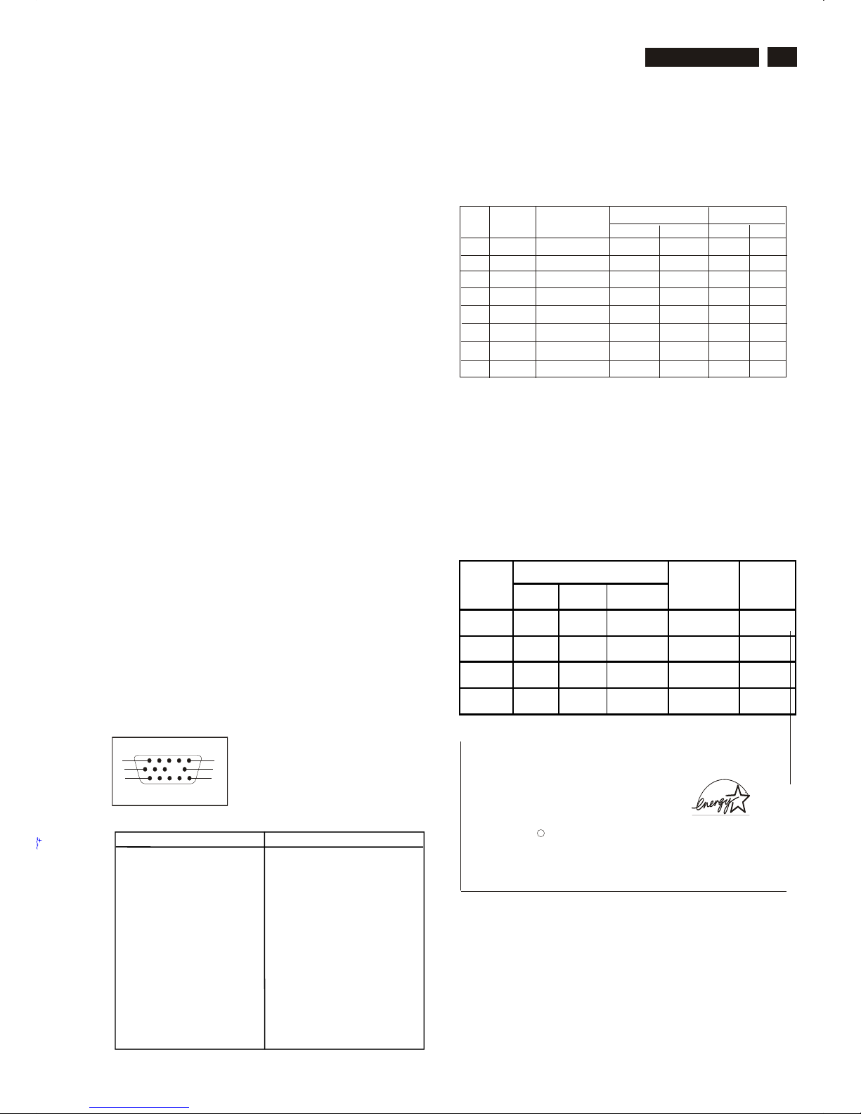
The 15-pin D-sub connector(male) of the signal cable :
Pin assignment :
1
10
6
11
15
5
If you have VESA's DPMS compliance display card or software installed
in your PC, the monitor can automatically reduce power consumption
when power saving function active. And if an input from keyboard,
mouse or other input devices is detected, the monitor will automatically
"wake up". The following table shows the power consumption and
signaling of this automatic power saving feature :
Automatic Power Saving
Data Storage
Factory preset modes:
This monitor has 8 factory-preset modes as indicated in the
following table :
Technical Specification*
CRT
Size and deflection :17 inch,
Deflection angle : 90 degrees
Dot pitch : 0.25mm with black matrix
Face treatment : Anti-glare, anti-static,
Light transmission
: 50% CPT, 55% PHL,52.8%
LG 52.6% SDI
Phosphor : P22
Recommended display area : 12.0" x 9.0" / 306 x 230 mm
Maximum display area
Scanning
Horizontal scanning : 30 - 71 KHz
Vertical : 50 - 160 Hz
Video
Video dot rate : 108 Mhz
Input impedance
-Video : 75 Ohms
- Sync : 4K7 Ohms
Signal input level : 0.7Vpp
Separate sync
flat/square
: 12.9" x 9.7" / 327 x 245 mm
scanning
Sync input signal : Separated sync. with TTL level
Sync polarities : Positive or negative
White Color Temperature
Chromaticity CIE coordinates:
o
at 9300 k x = 0.283 +/- 0.015 y = 0.297 +/- 0.015
o
at 6500 k x = 0.313 +/- 0.015 y = 0.329 +/- 0.015
Carton box
Size (with pedestal) : 493(W)x520(H)x556(D)
Net weight : 15 Kg
Power supply : 90 - 264 VAC, 50/60 +/ - 3Hz
Power consumption : 90 Watts Max.
Operating condition
OO
Temperature : 0 C - 40 C
Relative Humidety : 10 % - 90 % (W/O condensation)
Storage condition
OO
Temperature : - 25 C - 65 C
Relative Humidity : 5 % - 95 % (W/O condensation)
ENERGY STAR is a U.S. registered mark. AS AN ENERGY STAR
PARTNER, DELL Computer Corporation HAS DETERMINED THAT
THIS PRODUCT MEETS THE ENERGY STAR GUIDELINES FOR
ENERGY EFFICIENCY.
R
®
This monitor is ENERGY STAR compliant.
®
As an ENERGY STAR Partner, PHILIPS has determined that
®
this product meets the ENERGY STAR guidelines for energy
efficiency
H
V
-
-
-
-
-
+
+
+
+
+
+
+
+
+
+
+
V(Hz)
H(KHz)
Frequen
Sync polarity
Resolution
1280 x 1024
1024 x 768
800 x 600
800 x 600
M02
M05
M06
M07
M08
M04
M03
M01
31.5
68.7
46.9
64.0
60.0
53.67
85
85
60
60
75
85
75
70
31.47
43.3
1024 x 768
Mode
VESA
VESA
VESA
VESA
VESA
VGA
VGA
640 x 480
640 x 480
720 x 400
VESA
.
Signal
H-Sync V-Sync Video
Compliance
Requirement
Power
On Active Active Active Mandatory . 75w
Off Inactive Active Blanked Mandatory . 2 w
Off Active Inactive Blanked Mandatory . 2 w
Off Inactive Inactive Blanked Mandatory 2 w
.
Pin nbr. Assignment
P1 Red video input
P2 Green video input
P3 Blue video input
P4 GND
P5 For selftest (PC
Ground)
P6 Red video ground
P7 Green video ground
P8 Blue video ground
P9 Not connected -- No pin
P10 Sync ground
P11 GND
P12 Bi-directional Data
P13 H SYNC
P14 V SYNC (VCLK)
P15 Data clock (SCL)
Go to cover page
3
3
Front control & OSD
4
Go to cover page
M32 107T4 GS_3
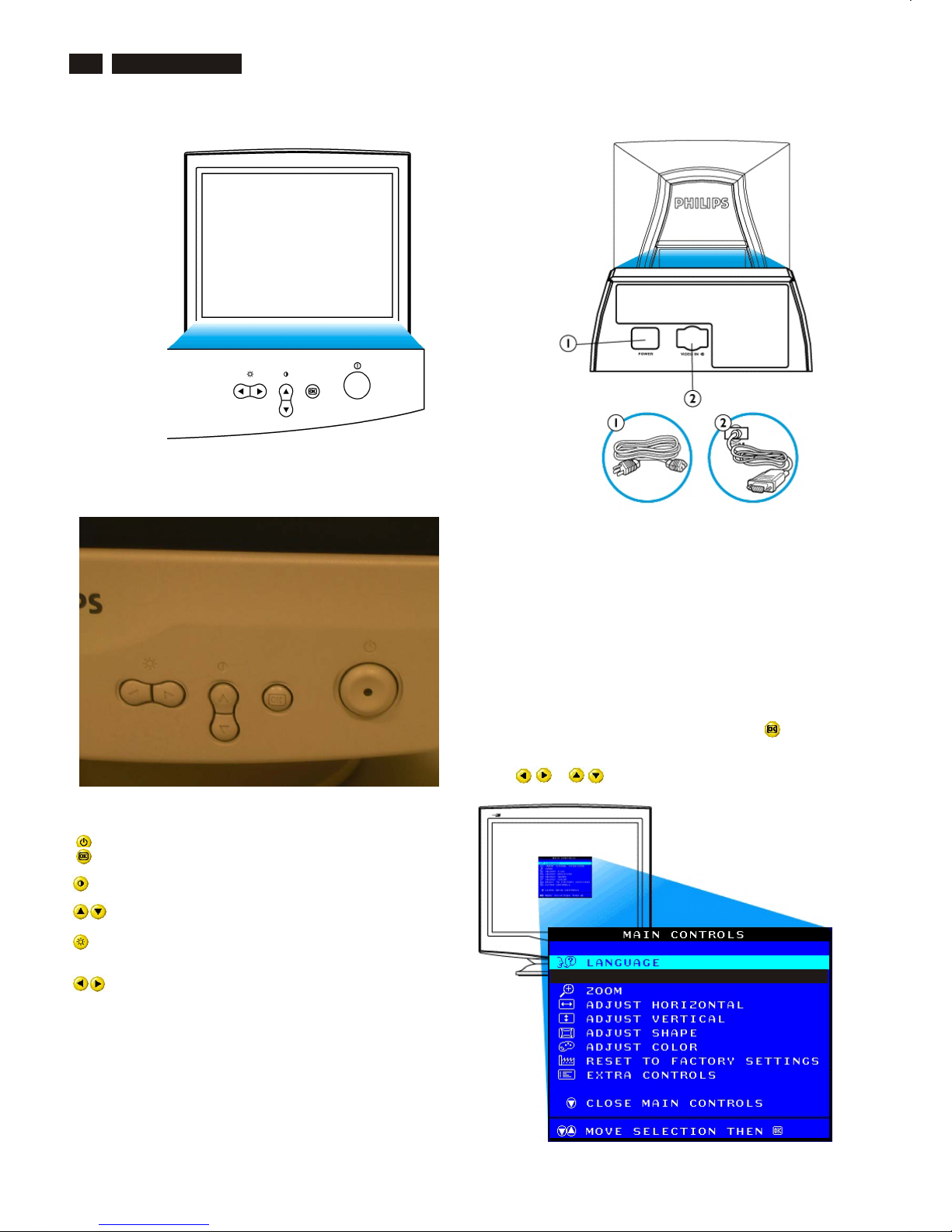
Description of the On Screen Display
What is the On-Screen Display?
Basic and simple instruction on the control keys.
This is a feature in all Philips monitors which allows an end-user to
adjust screen performance of monitors directly though an on-screen
instruction window. The user interface provides user-friendliness and
ease-of-use when operating the monitor.
On the front controls of your monitor, once you press the button, the
On Screen Display (OSD) Main Controls window will pop up and you
can now start making adjustments to your monitor's various features.
Use the or the keys to make your adjustments within.
Front View
Front control
Power button switches your monitor on.
OK button which when pressed will take you to the OSD
controls
Contrast hotkey. When the UP arrow is pressed, the
adjustment controls for the CONTRAST will show up.
UP and DOWN buttons are used when adjusting the OSD of
your monitor
LEFT and RIGHT buttons, like the UP and DOWN buttons, are
also used in adjusting the OSD of your monitor.
Brightness hotkey. When the RIGHT arrow is pressed,
the adjustment controls for BRIGHTNESS will show up.
Rear view
1. Power in - attach power cable here.
2. Video In - this is a cable which is already attached to your monitor.
Connect the other end of the cable to your PC.
5
OSD menu tree
Go to cover page
M32 107T4 GS_3
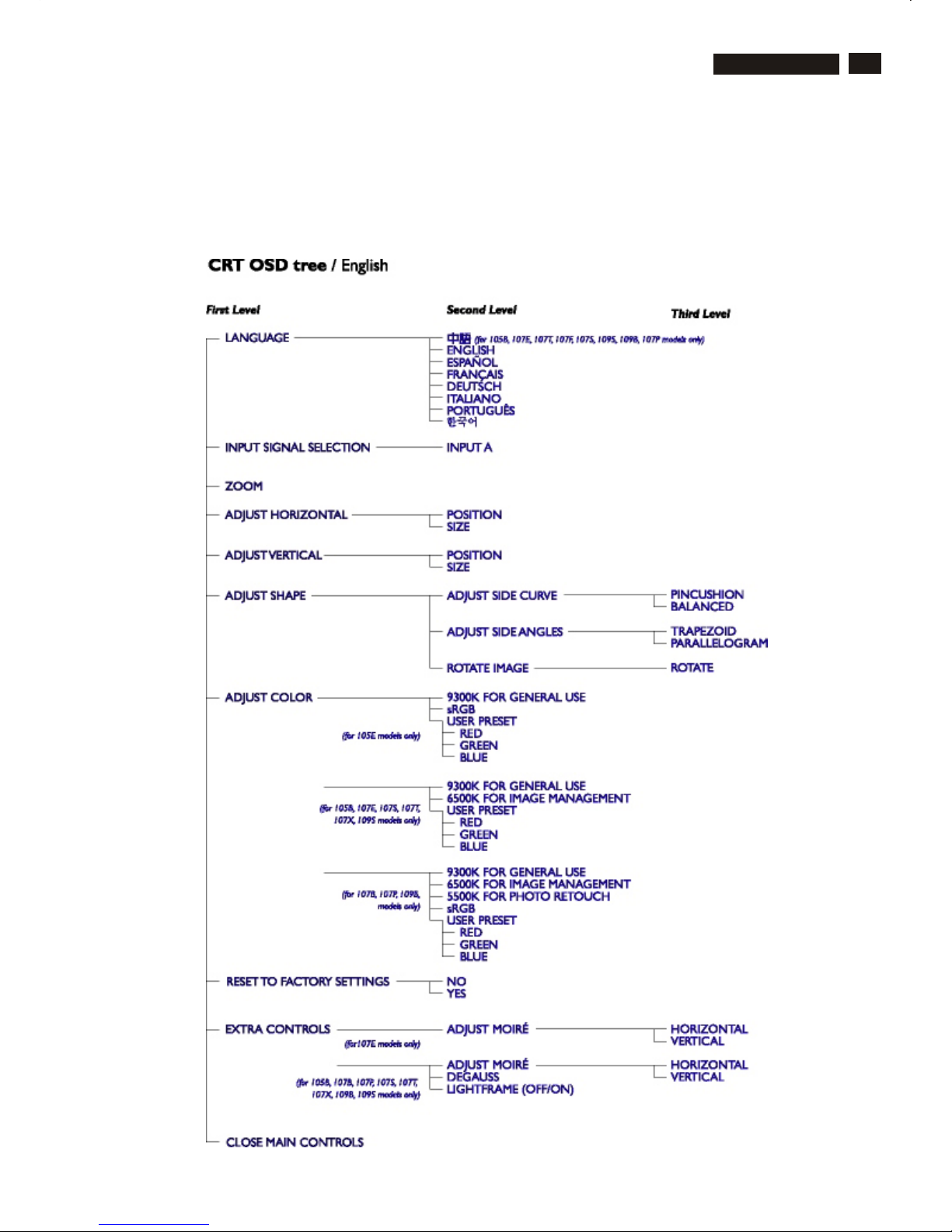
The OSD Tree
Below is an overall view of the structure of the On-Screen
Display. You can use this as reference when you want to
later on work your way around the different adjustments.
6
M32 107T4 GS_3
OSD Adjustments
The OSD Controls
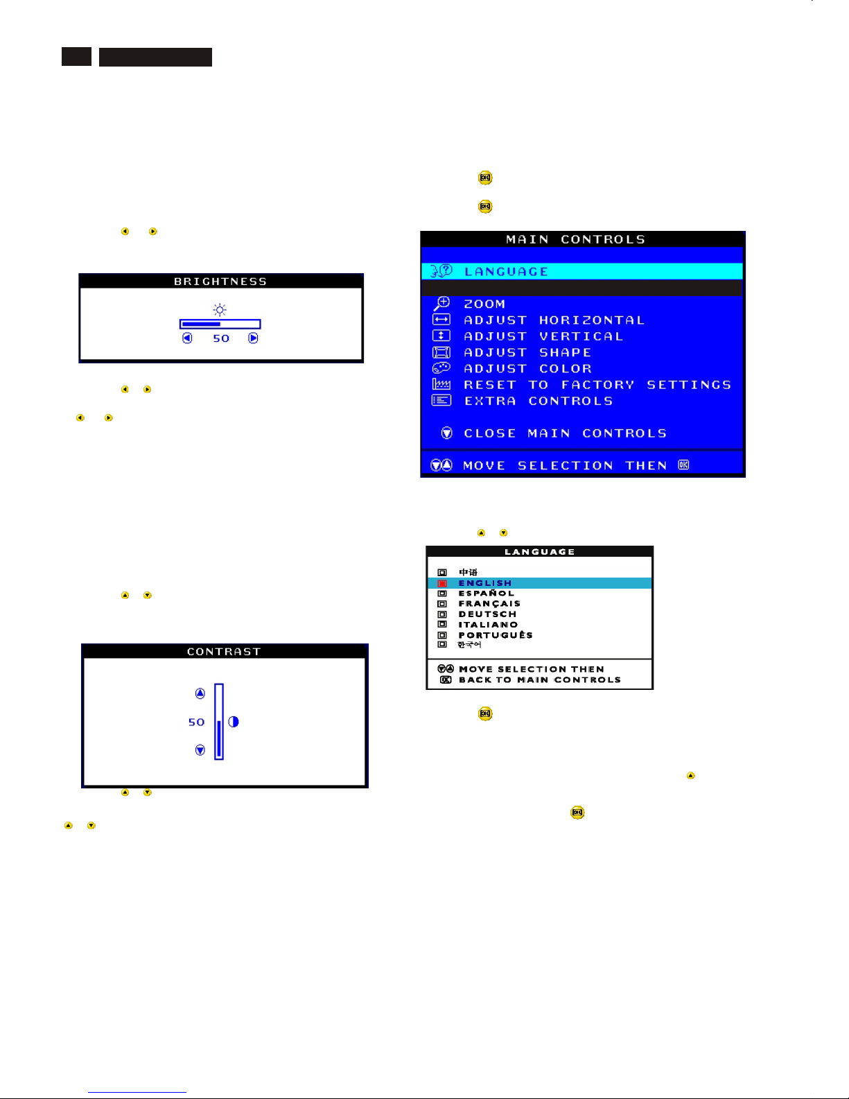
BRIGHTNESS
To adjust your screen's brightness, follow the steps below. Brightness is
the overall intensity of the light coming from the screen. A 50%
brightness is recommended.
1) Press the or button on the monitor. The BRIGHTNESS window
appears.
2) Press the or button to adjust the brightness.
3) When the brightness is adjusted to the level desired, stop pressing
the or button and after three seconds the BRIGHTNESS window
will disappear with the new adjustment saved.
After the BRIGHTNESS window has disappeared, to
continue to the CONTRAST window, follow the steps under CONTRAST.
CONTRAST
To adjust your screen's contrast, follow the steps bellow. Contrast is the
difference between the light and dark areas on the screen. A 100%
contrast is recommended.
1) Press the or button on the monitor. The CONTRAST window
appears.
2) Press the or button to adjust the contrast.
3) When the contrast is adjusted to the level desired, stop pressing the
or button and after three seconds the CONTRAST window will
disappear with the new adjustment saved.
After the CONTRAST window has disappeared, to
continue to the MAIN CONTROLS, follow the steps under LANGUAGE
Smart Help
Smart Help
LANGUAGE
The ON SCREEN DISPLAY shows its settings in one of five languages.
The default is English, but you can select French, Spanish, German, or
Italian.
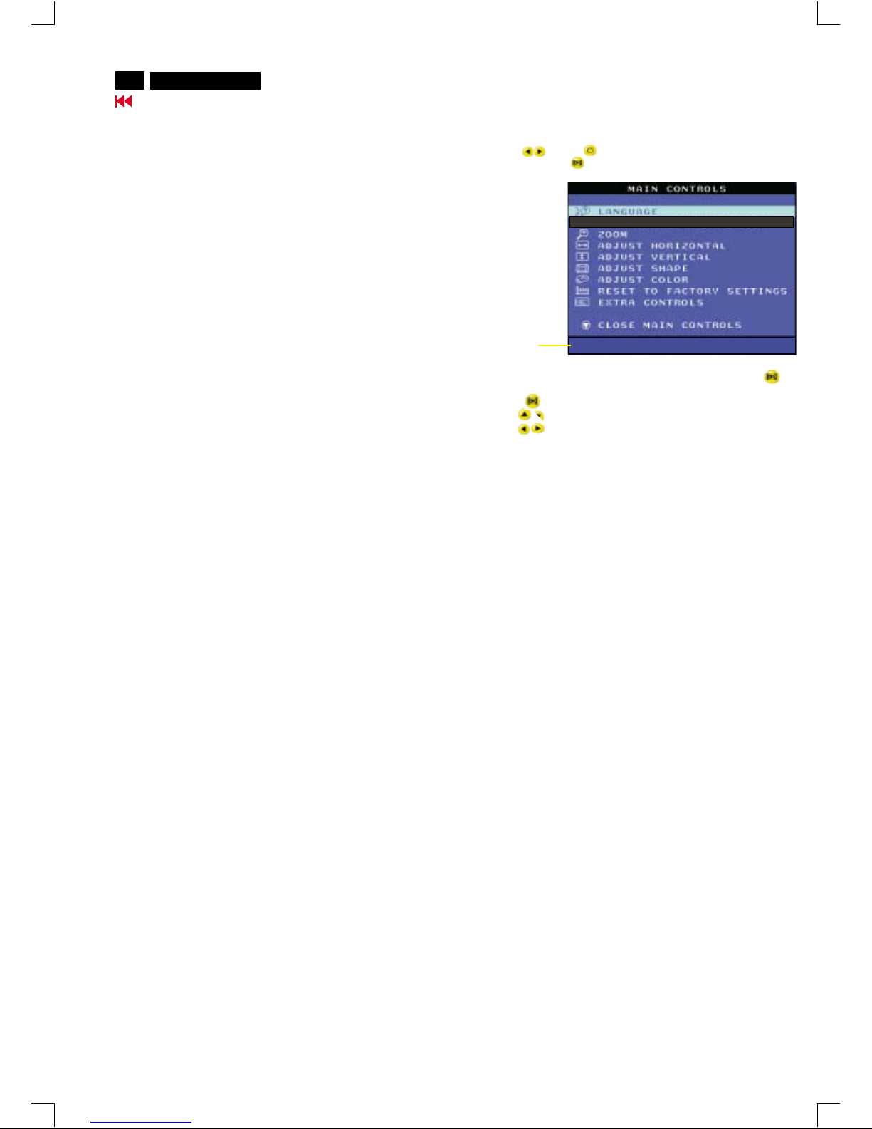
1) Press the button on the monitor. The MAIN CONTROLS window
appears. LANGUAGE should be highlighted.
2) Press the button again. The LANGUAGE window appears.
3) Press the or button until the desired language is highlighted.
4) Press the button to confirm your selection and return to MAIN
CONTROLS window. CLOSE MAIN CONTROLS will be highlighted...
After returning to MAIN CONTROLS . . .
. . . to continue to INPUT SIGNAL SELECTION, press the button until
INPUT SIGNAL SELECTION is highlighted. Next, follow steps 3 - 5
under INPUT SIGNAL SELECTION.
. . . to exit completely, press the button
Smart Help
Go to cover page

7
OSD Adjustments (Continued)
M32 107T4 GS_3
Go to cover page
ZOOM
ZOOM increases or decreases the size of the images on your screen.
To adjust the ZOOM follow the steps below.
1) Press the button on the monitor. The MAIN CONTROLS window
appears.
2) Press the button until ZOOM is highlighted.
3) Press the button. The ZOOM window appears.
4) Press the or button to adjust ZOOM.
5) Press the button to confirm your selection and return to the MAIN
CONTROLS window. CLOSE MAIN CONTROLS will be highlighted.
After returning to MAIN CONTROLS . . .
. . . to continue to ADJUST HORIZONTAL, press the button until
ADJUST HORIZONTAL is highlighted. Next, follow steps 3 - 7 under
ADJUST HORIZONTAL.
. . . to exit completely, press the button
ADJUST HORIZONTAL
ADJUST POSITION under ADJUST HORIZONTAL shifts the image on
your screen either to the left or right. Use this feature if your image does
not appear centered. ADJUST SIZE under ADJUST HORIZONTAL
expands or controls the image on your screen, pushing it out toward the
left and right sides or pulling it in toward the center.
1) Press the button on the monitor. The MAIN CONTROLS window
appears.
2) Press the button until ADJUST HORIZONTAL is highlighted.
Smart Help
3) Press the button. The ADJUST HORIZONTAL window appears.
ADJUST POSITION should be highlighted.
4) Press the or button to move the image to the left or right.
5) When the position is adjusted, press the button to return to MAIN
CONTROLS window, or press the to highlight ADJUST SIZE.
6) To adjust the horizontal size, press the or button.
7) When the size is adjusted, press the button to return to MAIN
CONTROLS window. CLOSE MAIN CONTROLS will be highlighted.
After returning to MAIN CONTROLS . . .
. . . to continue to ADJUST VERTICAL, press the button until
ADJUST VERTICAL is highlighted. Next, start with step 3 under
ADJUST VERTICAL and follow the directions.
. . . to exit completely, press the button
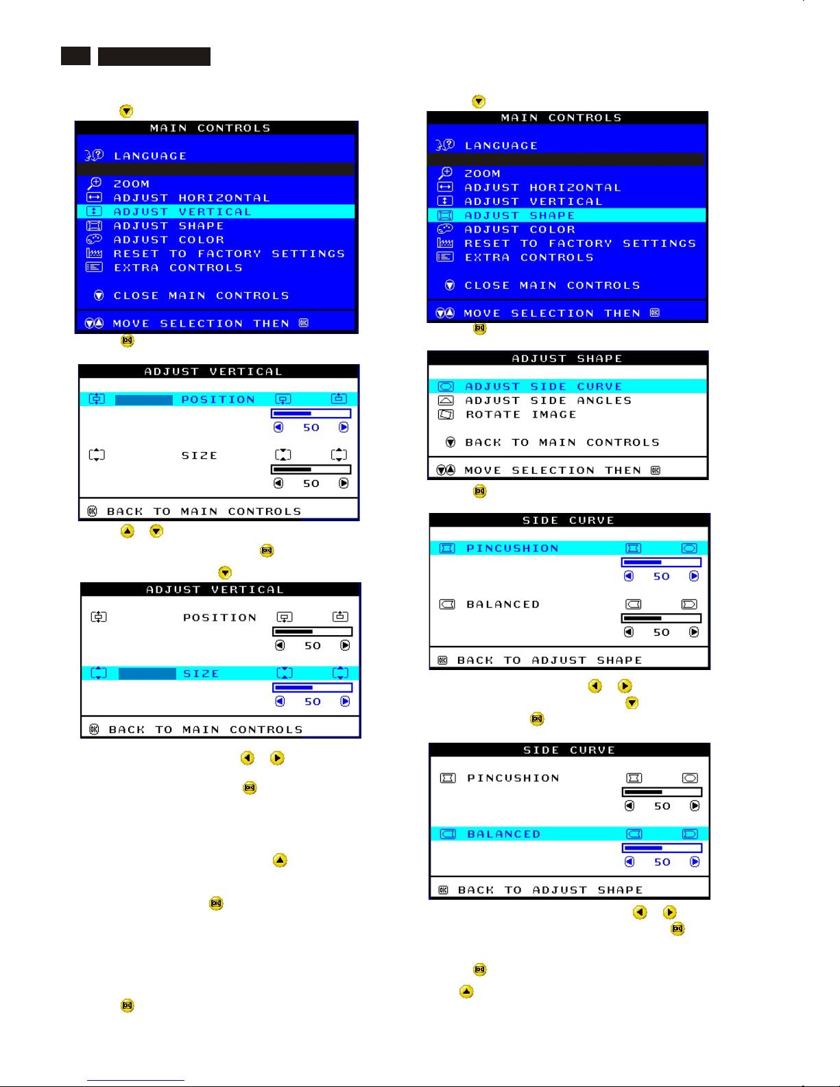
ADJUST VERTICAL
ADJUST POSITION under ADJUST VERTICAL shifts the image on
your screen either up or down. Use this feature if your image does not
appear centered. ADJUST SIZE under ADJUST VERTICAL expands or
controls the image on your screen, pushing it out toward the top or
bottom or pulling it in toward the center.
1) Press the button on the monitor. The MAIN CONTROLS window
appears.
Smart Help
8
Go to cover page
OSD Adjustments (Continued)
M32 107T4 GS_3
2) Press the button until ADJUST VERTICAL is highlighted.
3) Press the button. The ADJUST VERTICAL window appears.
ADJUST POSITION should be highlighted.
4) Press the or button to move the image up or down.
5) When the position is adjusted, press the button to return to MAIN
CONTROLS window, or press the button to highlight ADJUST SIZE.
6) To adjust the vertical size, press the or button.
7) When the size is adjusted, press the button to return to MAIN
CONTROLS window. CLOSE MAIN CONTROLS will be highlighted.
After returning to MAIN CONTROLS . . .
. . . to continue to ADJUST SHAPE, press the button until ADJUST
SHAPE is highlighted. Next, start with step 3 under ADJUST SHAPE
and follow the directions.
. . . to exit completely, press the button
ADJUST SHAPE
ADJUST SIDE CURVE
ADJUST SIDE CURVE under ADJUST SHAPE allows you to adjust two
of the five preset options. These two options are PINCUSHION and
BALANCED pincushion. Note: use these features only when the picture
is not square.
1) Press the button on the monitor. The MAIN CONTROLS window
appears.
Smart Help
2) Press the button until ADJUST SHAPE is highlighted.
3) Press the button. The ADJUST SHAPE window appears.
ADJUST SIDE CURVE should be highlighted.
4) Press the button. The SIDE CURVE window appears.
PINCUSHION should be highlighted.
5) To adjust the pincushion, press the or button.
6) When the pincushion is adjusted, press the button to highlight
BALANCED or press the button to return to the ADJUST SHAPE
window.
7) To adjust the balanced pincushion, press the or button.
8) When the balanced pincushion is adjusted, press the button to
return to the ADJUST SHAPE window. BACK TO MAIN WINDOWS will
be highlighted.
9) Press the button to return to the MAIN CONTROLS window, or
press the button until ADJUST SIDE ANGLES is highlighted.
9
Smart Help After returning to MAIN CONTROLS . . .
...to continue to ADJUST SIDE ANGLES, start with step 5 under
ADJUST SIDE ANGLES and follow the directions.
...to exit completely, press the button twice.
...to adjust only the BALANCED pincushion, follow steps 1 - 4 above,
then press the button, and follow steps 7 - 9.
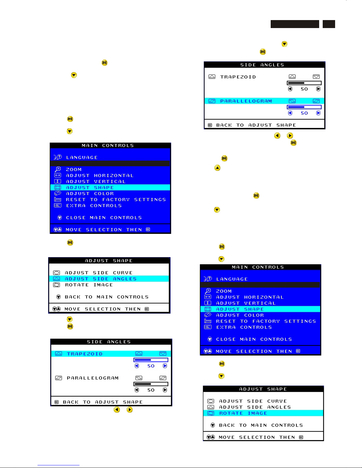
ADJUST SIDE ANGLES
ADJUST SIDE ANGLES under ADJUST SHAPE allows you to adjust
two of the five preset options. These two options are TRAPEZOID and
PARALLELOGRAM. Note: use these features only when the picture is
not square.
1) Press the button on the monitor. The MAIN CONTROLS window
appears.
2) Press the button until ADJUST SHAPE is highlighted.
3) Press the button. The ADJUST SHAPE window appears.
ADJUST SIDE CURVE should be highlighted.
4) Press the button to highlight ADJUST SIDE ANGLES.
5) Press the button. The SIDE ANGLES window appears.
TRAPEZOID should be highlighted.
6) To adjust the trapezoid, press the or button.
7) When the trapezoid is adjusted, press the button to highlight
PARALLELOGRAM or press the button to return to the ADJUST
SHAPE window.
8) To adjust the parallelogram, press the or button.
9) When the parallelogram is adjusted, press the button to return to
the ADJUST SHAPE window. BACK TO MAIN WINDOWS will be
highlighted.
10) Press the button to return to the MAIN CONTROLS window, or
press the button until ROTATE IMAGE is highlighted.
After returning to MAIN CONTROLS . . .
...to continue to ROTATE IMAGE, start with step 5 under ROTATE
IMAGE and follow the directions.
...to exit completely, press the button twice.
...to adjust only the PARALLELOGRAM, follow steps 1 - 4 above, then
press the button, and follow steps 7 -9
ROTATE IMAGE
ROTATE IMAGE under ADJUST SHAPE allows you to adjust one of
the five preset options. These two options are PINCUSHION and
BALANCED pincushion. Note: use this feature only when the picture is
not square.
1) Press the button on the monitor. The MAIN CONTROLS window
appears.
2) Press the button until ADJUST SHAPE is highlighted.
3) Press the button. The ADJUST SHAPE window appears.
ADJUST SIDE CURVE should be highlighted.
4) Press the arrow until ROTATE IMAGE is highlighted.
Smart Help
Go to cover page
OSD Adjustments (Continued)
M32 107T4 GS_3
10
Go to cover page
OSD Adjustments (Continued)
M32 107T4 GS_3
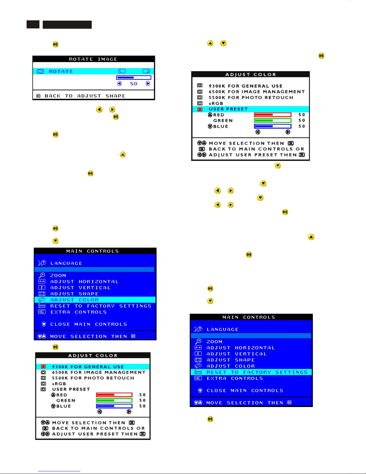
5) Press the button. The ROTATE IMAGE window appears. ROTATE
should be highlighted.
6) To adjust the rotation, press the or button.
7) When the rotation is adjusted, press the button to return to the
ADJUST SHAPE window. BACK TO MAIN CONTROLS should be
highlighted.
8) Press the button to return to MAIN CONTROLS.
After returning to MAIN CONTROLS . . .
. . . to continue to ADJUST COLOR, press the button until ADJUST
COLOR is highlighted. Next, start with step 3 under ADJUST COLOR
and follow the directions.
...to exit completely, press the button twice.
ADJUST COLOR
Your monitor has two preset options you can choose from. The first
option is for GENERAL USE, which is fine for most applications. The
second option is for GAMES, which is for playing computer games.
When you select one of these options, the monitor automatically adjusts
itself to that option. There is also a third option, USER PRESET, which
allows you to adjust the colors on your screen to a setting you desire.
1) Press the button on the monitor. The MAIN CONTROLS window
appears.
2) Press the button until ADJUST COLOR is highlighted.
3) Press the button. The ADJUST COLOR window appears.
Smart Help
4) Press the or button to highlight 9300K for GENERAL USE,
6500K for GAMES, or USER PRESET.
5) Once you have highlighted GENERAL USE or GAMES, press the
button to confirm you selection and return to the MAIN CONTROLS
window. CLOSE MAIN CONTROLS will be highlighted.
6a) If USER PRESET is highlighted, press the button to highlight
RED. Next, press the LEFT CURSOR or RIGHT CURSOR button to
adjust the color red.
6b) When finished with RED, press the button to highlight GREEN.
Next, press the or button to adjust the color green.
6c) When finished GREEN, press the button to highlight BLUE.
Next, press the or button to adjust the color blue.
6d) When all adjustments are complete, press the button to confirm
your adjustments and return to the MAIN CONTROLS window. CLOSE
MAIN CONTROLS will be highlighted.
After returning to MAIN CONTROLS. . .
. . . to continue to RESET TO FACTORY SETTINGS, press the
button until RESET TO FACTORY SETTINGS is highlighted. Next, start
with step 3 under RESET TO FACTORY SETTINGS.
. . . to exit completely, press the button.
RESET TO FACTORY SETTINGS
RESET TO FACTORY SETTINGS returns everything in all the windows
to factory presets.
1) Press the button on the monitor. The MAIN CONTROLS window
appears.
2) Press the button until RESET TO FACTORY SETTINGS is
highlighted.
3) Press the button. The RESET TO FACTORY SETTINGS window
appears.
Smart Help

11
OSD Adjustments (Continued)
Go to cover page
M32 107T4 GS_3
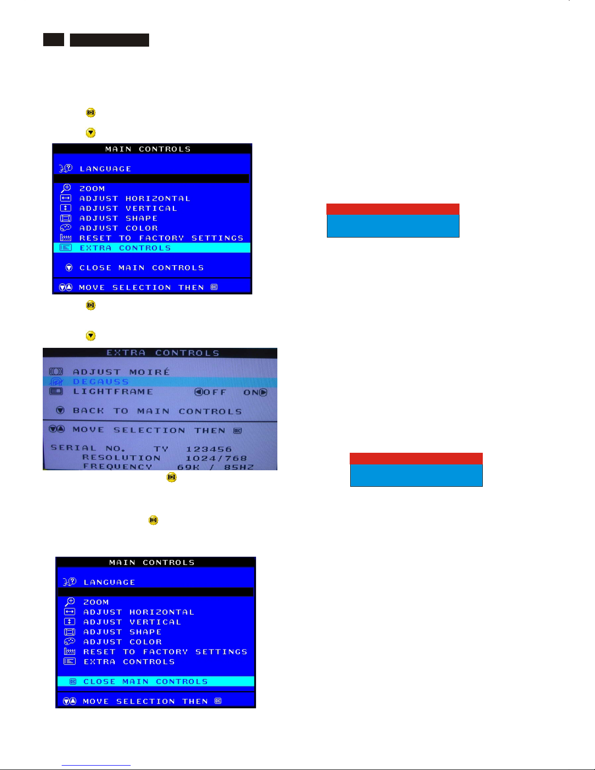
ADJUST MOIRE
EXTRA CONTROLS is a set of three features, including ADJUST
MOIRE. Moire is a fringe pattern arising from the interference between
two superimposed line patterns. To adjust your moire, follow the steps
below. Note: Use only if necessary. By activating ADJUST MOIRE,
sharpness can be affected.
1) Press the button on the monitor. The MAIN CONTROLS window
appears.
2) Press the DOWN CURSOR button until EXTRA CONTROLS is
highlighted.
3) Press the button. The EXTRA CONTROLS window appears. will
ADJUST MOIRE will be highlighted.
4) Press the button. The ADJUST MOIRE window appears.
HORIZONTAL will be highlighted.
5) To adjust the horizontal moire, press the or button.
4) Press the or button to select YES or NO. NO is the default.
YES returns all settings to their original factory adjustments.
5) Press the button to confirm your selection and return to the MAIN
CONTROLS window. CLOSE MAIN CONTROLS will be highlighted.
After returning to MAIN CONTROLS . . .
. . . to continue to EXTRA CONTROLS, press the button until
EXTRA CONTROLS is highlighted. Next, start with step 3 under EXTRA
CONTROLS.
. . . to exit completely, press the button.
EXTRA CONTROLS
Smart Help
6) When the horizontal moire is adjusted, press the button to
highlight VERTICAL.
7) To adjust the vertical moire, press the or button.
8) When the vertical moire is adjusted, press the button to return to
the EXTRA CONTROLS window. BACK TO MAIN CONTROLS will be
highlighted.
Smart Help After returning to MAIN CONTROLS . . .
. . . to continue to DEGAUSS, press the button until DEGAUSS is
highlighted. Next, start with step 3 under EXTRA CONTROLS,
DEGAUSS.
. . . to exit completely, press the button.
12
OSD Adjustments (Continued), Troubleshooting
Go to cover page
M32 107T4 GS_3
Smart Help After returning to MAIN CONTROLS . . .
. . . to exit completely, press the button.
CLOSE MAIN CONTROLS
Monitor Specific Troubleshooting
Self-Test Feature Check (STFC)
Your monitor provides a self-test feature that allows you to check
whether your monitor is functioning properly. If your monitor and
computer are properly connected but the monitor screen remains
dark, run the monitor self-test by performing the following steps:
1. Turn off both your computer and the monitor.
2. Unplug the video cable from the back of the computer.
3. Turn on the monitor.
If the monitor is functioning properly, you will see a OSD
message as shown in the following illustration:
This box also appears during normal system operation if the
video cable becomes disconnected or damaged. This box
will remain on for one minute, go off five seconds, then on for
one minute, and will repeat cycle.
1. Turn off your monitor and reconnect the video cable;
then turn on both your computer and the monitor.
2. While in self-test mode, the LED remains green and the
pattern remains on and stationary.
If your monitor screen still remains dark after you use the
previous procedure, check your video controller and computer
system; your monitor is functioning properly.
NO SIGNAL INPUT
If there is something wrong with the input signal, a message
appears on the screen although the power indicator LED is
still on. The message may indicate that the monitor is NO
SIGNAL INPUT or that you need to check the signal cable.
NO SIGNAL INPUT
ATTENTION
CHECK SIGNAL CABLE
ATTENTION
DEGAUSS
EXTRA CONTROLS is a set of three features, including DEGAUSS.
Degaussing removes electromagnetic build up that may distort the color
on your screen.
1) Press the button on the monitor. The MAIN CONTROLS window
appears.
2) Press the button until EXTRA CONTROLS is highlighted.
3) Press the button. The EXTRA CONTROLS window appears.
ADJUST MOIRE will be highlighted.
4) Press the button until DEGAUSS is highlighted.
5) To degauss your screen, press the button. Your screen will be
degaussed, then the MAIN CONTROLS window will reappear. CLOSE
MAIN CONTROLS will be highlighted.
13
Lock/Unlock, Factory Mode, Burn In, Service Mode
Go to cover page
M32 107T4 GS_3
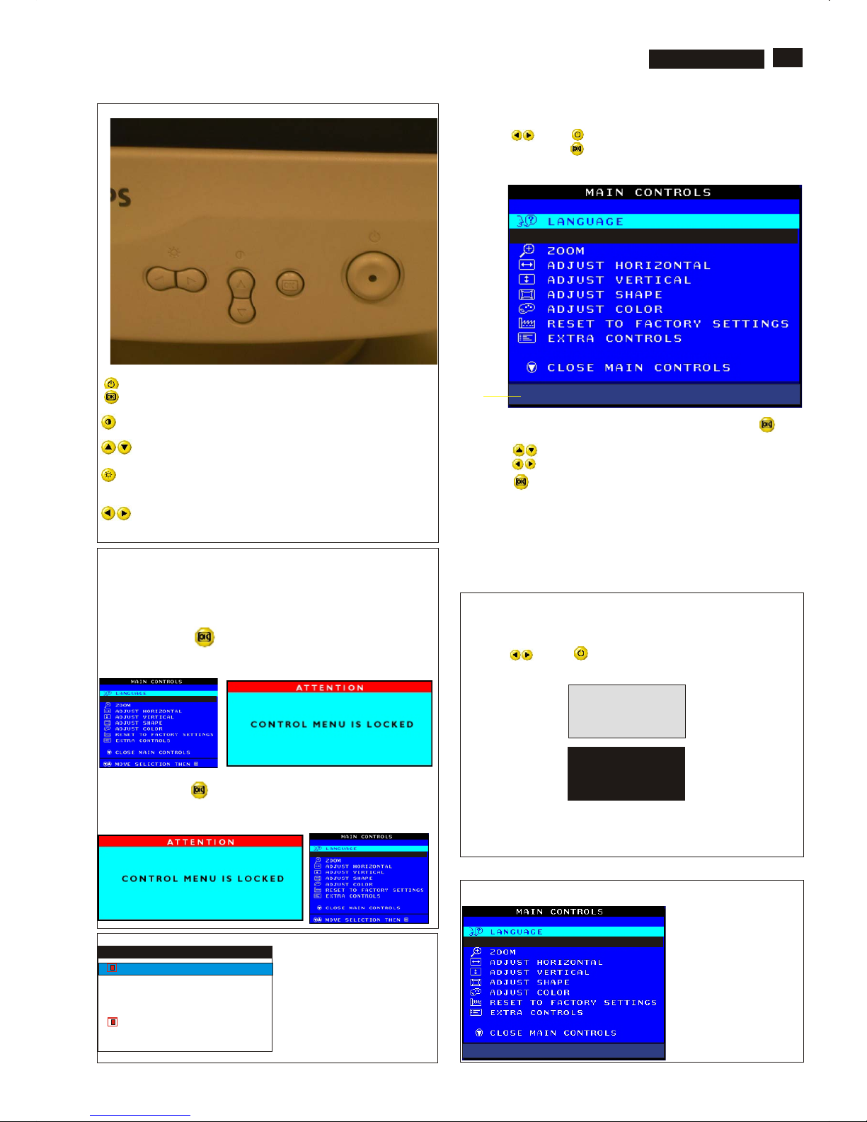
Front Control
Power button switches your monitor on.
OK button which when pressed will take you to the OSD
controls
Contrast hotkey. When the UP arrow is pressed, the
adjustment controls for the CONTRAST will show up.
UP and DOWN buttons are used when adjusting the OSD of
your monitor
LEFT and RIGHT buttons, like the UP and DOWN buttons, are
also used in adjusting the OSD of your monitor.
Brightness hotkey. When the RIGHT arrow is pressed,
the adjustment controls for BRIGHTNESS will show up.
OSD Lock
OSD lock is a feature which disables the OSD controls. It can be used
when the monitor is set up for demonstration purposes or when
adjustment of the OSD is not desirable.
Switch on OSD lock feature:
Press and hold the button continuously for 15 seconds.
Release the button when the message
"CONTROL MENU IS LOCKED" appears.
Switch off OSD lock feature:
Press and hold the button continuously for 15 seconds or until the
message window "CONTROL MENU IS LOCKED" disappears, and
"MAIN CONTROLS" appears.
To access BURN IN mode
First of all, monitor displays an image.
1. Disconnect the video cable (interface cable).
2. Turn off monitor
3. Press " " and " " simultaneously on the front control
panel,then the BURN IN mode comes on the screen of monitor
as below.
50 seconds around
5 seconds around
repeatly
4. Reconnect the video cable, then return to normal image.
SERVICE MODE (Indication-Factory mode)
MODEL SELECT
00010
M32 107E/T4P V2.00 20020523
------------------------>
00010: stands for
1. using 10 hours already.
2. turn on/off 10 times.
3. using several hours
+ turn on/off monitor.
Default setting of MODEL SELECT (Do not change it.)
MODEL SELECT
107E4
107E4 (TILT REVERSE)
107T4
107T4 (TILT REVERSE)
RESERVE
SWDDC
LF2
LF3
MODEL SELECT
M32 107E/T4P V2.0 20020523
Factory
Mode
Indicator
To access factory mode
1. Turn off monitor (don't turn off PC)
2. Press " " and " " simultaneously on the front control
panel,then press " ",wait till the OSD menu with characters
M32 107E/T4P V2.0 20020523 (below OSD menu)" come on the
screen of monitor.
3. If OSD menu disappears on the screen of monitor, press " "
again (anytime), then the OSD menu comes on the screen again.
4. Using " " : to select OSD menu.
5. Using " " : to increase or decrease the setting.
6. Using " " to access/confirm the selection.
To leave factory mode
7. After alignment of factory mode, turn off monitor (if you do not turn
off monitor, the OSD menu is always at the factory mode), then
turn on monitor again (at this moment, the OSD menu goes back
to user mode).
X
Go to cover page
14
M32 107T4 GS_3
Warning and Notes
Fig.1
V
Warnings
1. Safety regulations require that the unit should be returned
in its original condition and that components identical to
the original components are used. The safety components
are indicated by the symbol .
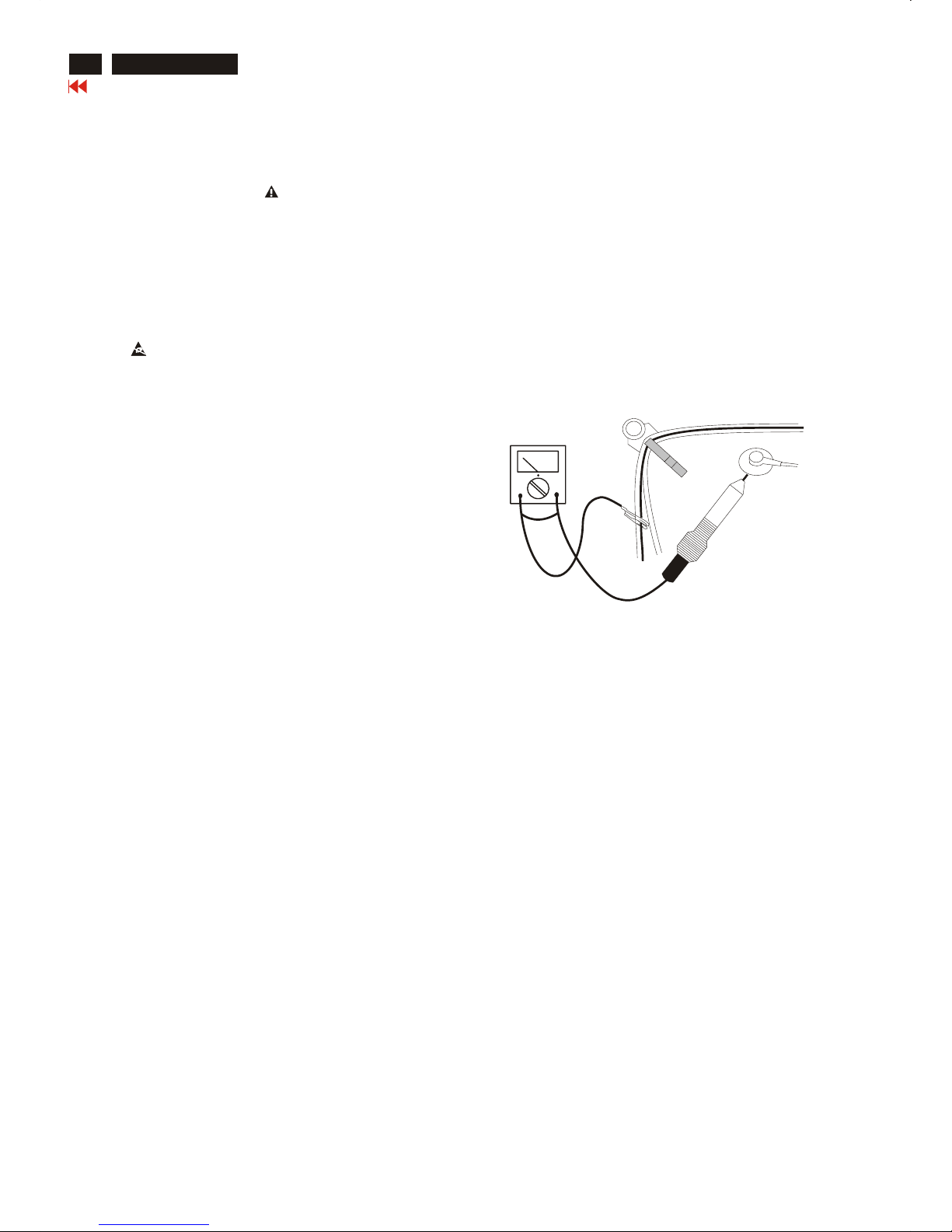
2. In order to prevent damage to ICs and transistors, all
high-voltage flash-overs must be avoided. In order to
prevent damage to the picture tube, the method shown
in Fig. 1 should be used to discharge the picture tube.
Use a high-voltage probe and a multimeter (position DC-V).
Discharge until the meter reading is 0 V (after approximately
30 seconds).
3. ESD
All ICs and many other semiconductors are sensitive to
electrostatic discharges (ESD). Careless handling during
repair can drastically shorten their life. Make sure that
during repair you are connected by a pulse band with
resistance to the same potential as the ground of the unit.
Keep components and tools also at this same potential.
4. When repairing a unit, always connect it to the AC Power
voltage via an isolating transformer.
5. Be careful when taking measurements in the high-voltage
section and on the picture tube panel.
6. It is recommended that saferty goggles be worn when
replacing the picture tube.
7. When making adjustments,use plastic rather than metal tools.
This will prevent any short-circuit or the danger of a
circuit becoming unstable.
8. Never replace modules or other components while the
unit is switched on.
9. Together with the defleciton unit, the picture tube is used
as an integrated unit. Adjustment of this unit during repair
is not recommended.
10. After repair, the wiring should be fastened in place with
the cable clamps.
11. All units that are returned for service or repair must pass
the original manufactures safety tests.
Notes
1. The direct voltages and waveforms are average voltages.
They have been measured using the Service test software
and under the following conditions :
- Mode : 640 * 480 (31.5kHz / 60Hz)
- Signal pattern : grey scale
- Adjust brightness and contrast control for the
mechanical mid-position (click position)
2. The picture tube panel has printed spark gaps.
Each spark gap is connected between an electrode of the
picture tube and the Aquadag coating.
3. The semiconductors indicated in the circuit diagram(s)
and in the parts lists are completely interchangeable per
position with the semiconductors in the unit, irrespective
of the type indication on these semiconductors.
Go to cover page
15
Mechanical Instructions
0. General
To be able to perform measurements and repairs on the "circuit
boards", these unit should placed in the service position first.
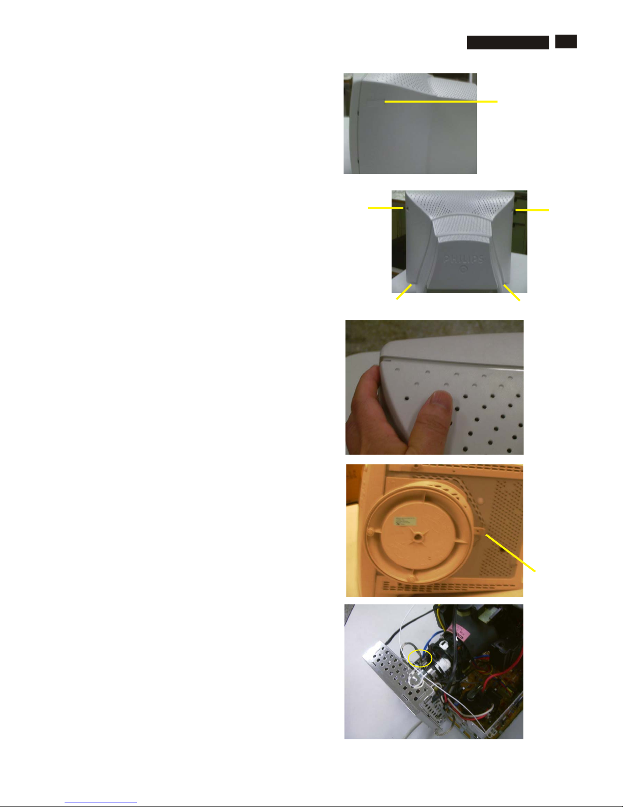
1.Remove the rear cover
-Remove right and left lib (screw cover) on the back cover
as shown in Fig. 1.
-Remove 4 screws as shown in Fig. 2.
-Remove back cover as shown in Fig. 3.
2. Remove pedestal as shown in Fig. 4.
3. Video panel
- Disconnect the wire between metal shield of Video panel and
CRT neck as shown in Fig. 5.
- Disconnect the CRT ground "1703" from Video panel.
lids (screw cover)
screw
screw
screw
screw
Fig. 1
Fig. 2
Fig. 3
Rear cover
Pedestal ass'y
Video Panel
Fig. 4
Fig. 5
=======>
================>
================>
M32 107T4 GS_3
Go to cover page
16
Mechanical Instructions
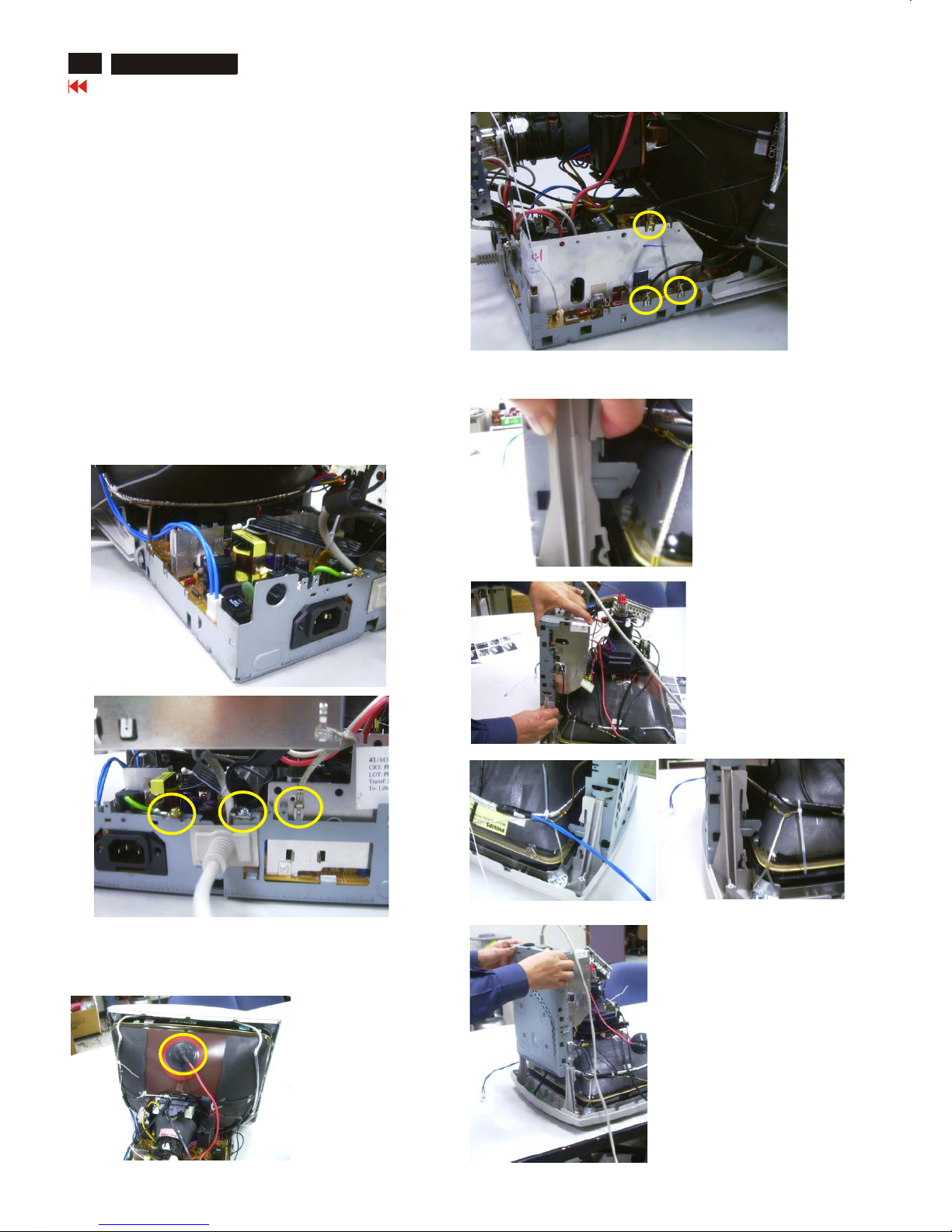
4. Main panel with Bottom Tray
- Disconnect the degaussing coil (1113)from Main panel
as shown in Fig. 6.
- Remove the video panel from CRT neck.
- Remove the "screw" of I/F cable from Main panel, grounding screw
, wire as shown in Fig. 7..
- Disconnect the CRT ground "1703" from Video panel.
- Disconnect the Hi-Pot cap from CRT as shown in Fig. 8..
- Disconnect yoke wire from "1601"(on Main Panel).
- Disconnect concellation connector "1402" (on Main Panel).
- Remove main panel with bottom tray as shown in Fig. 10 to Fig. 14.
- Disconnect connector "1604" and all the wires as shown in Fig. 9.
- Disconnect connector of "1802".
Fig. 6
(1113)
(1604)
Fig. 9
Fig. 11
Fig. 13
Fig. 12
Fig. 14
Fig. 10
Fig. 7
Fig. 8
Hi-Pot cap
screw - grounding
=======>
=======>
=======>
===============>
===============>
=============>
======>
======>
======>
======>
=====
=>
============>
Press
Press
Pull-up a little bit
Pull-up
Left &
Right
=======>
M32 107T4 GS_3
Go to cover page
17
Mechanical Instructions
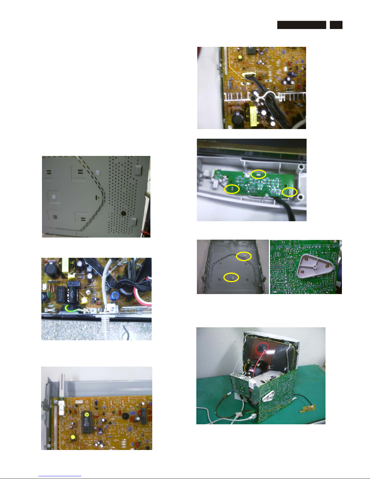
5. How to remove Main Panel (Chassis)
After remove "Main panel with bottom tray":
- Remove Interface cable from bottom tray as shown in Fig. 16.
7. SERVICE POSITION
Reconnect connectors, some wires and panels (chassis),
service position can be available for DC/AC measurement
as shown in Fig. 22.
- Remove a screw from back of bottom tray as shown in Fig. 15.
- Remove a screw from Main panel as shown in Fig. 16.
- Remove 2 screws from Main panel as shown in Fig. 17.
- Remove a screw from Main panel as shown in Fig. 18.
- Remove Main panel from bottom tray.
6. How to remove Front Control Panel (Chassis)
- Release 3 plastic claws as shown in Fig. 19.
- Remove Front control panel from Front Cabinet.
Fig. 15
screw
(black)
screw
Fig. 16
Fig. 17
Fig. 18
Fig. 19
Fig. 20
(plastic on bottom tray)
plastic claw
================>
================>
================>
=====================>
=============>
=====>
=====>
==============>
=============>
================>
============>
I/F cable
Rear view of Bottom Tray
screw
(black)
screw
(black)
Front control
panel
Front control
panel
Main panel
Video panel
screw
Fig. 21
(copper track side view
on Main panel)
Fig. 22 SERVICE POSITION
M32 107T4 GS_3
18
Go to cover page
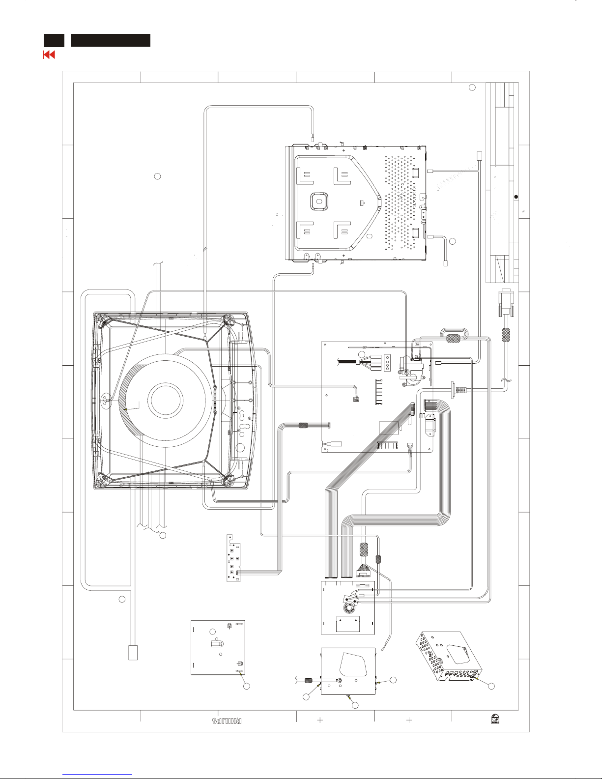
Wiring Diagram
M32 107T4 GS_3
1 2 3 4 5 6 7 8 9
A
B
C
D
E
F
654321
E
D
C
B
A
F
DATE
DATE
NAME
NAME
CHECK
CHECK
SUPERS .
SUPERS .
A2
7 8 9
MODEL :
MODEL :
CONTROLPCB
8639 000 12287
8639 000 12287
MAX LIN
MAX LIN
10 132 - 1
TY
TY
C PHILIPS ELECTRONICS INDUSTRIES
C PHILIPS ELECTRONICS INDUSTRIES
(TAIWAN)LTD - CED
(TAIWAN)LTD - CED
1
4
1
8891
8891
1
8801
2002-05-20
17" M32 GS3 107T4-70K CMTR
17" M32 GS3 107T4-70K CMTR
TYPE :107T41/00C
TYPE :107T41/00C
BRAND :PHILIPS(MPRII)
BRAND :PHILIPS(MPRII)
--------
--------
2
1113
3
11
1301
13
1
2002-05-20
2002-05-20
1402
3
TO NECK
TO NECK
1714
10
1
11
1
1712
1712
8502
CONNECT TO VIDEO SHIELD -TOP POINT
CONNECT TO VIDEO SHIELD -TOP POINT
D
CONNECT TO VIDEO SHIELD -TOP POINT
CONNECT TO VIDEO SHIELD -TOP POINT
C
CONNECT TO VIDEO SHIELD -TOP POINT
CONNECT TO VIDEO SHIELD -TOP POINT
E
COPPER FOIL
COPPER FOIL
CONNECT TO MAIN-PCB 1604
CONNECT TO MAIN-PCB 1604
(EXCEPT FOR CPT TUBE TCO MODEL)
(EXCEPT FOR CPT TUBE TCO MODEL)
(ONLY FOR CPTTUBE TCO MODEL)
(ONLY FOR CPTTUBE TCO MODEL)
C
E
D
M32 107T4
M32 107T4
10
1
TO YOKE
TO YOKE
1601
1
4
1802
1
4
1
1713
BOTTOM PLATE(METAL TRAY)
BOTTOM PLATE(METAL TRAY)
YOKE
YOKE
MAIN PCB ASSY
MAIN PCB ASSY
CONTROL PCB ASSY
CONTROL PCB ASSY
VIDEO PCB ASSY
VIDEO PCB ASSY
VIDEO SHIELD TOP
VIDEO SHIELD TOP
1604
CONNECT TO MAIN-PCB 1604
CONNECT TO MAIN-PCB 1604
CONNECT TO VIDEO SHIELD -TOP POINT
CONNECT TO VIDEO SHIELD -TOP POINT
CONNECT TO VIDEO SHIELD -TOP POINT
CONNECT TO VIDEO SHIELD -TOP POINT
A
B
RED
WHITE
WHITE
WHITE
WHITE
RED
A
B

Go to cover page
Hex Data of DDC2B
19
M32 107T4 GS_3
**********************************************************************
M32 107T4 71K CPT Tube EDID log file
**********************************************************************
Vendor/Product Identification
ID Manufacturer Name : PHL
ID Product Code : E00A (HEX.)
ID Serial Number : 1E240 (HEX.)
Week of Manufacture : 10
Year of Manufacture : 2002
EDID Version, Revision
Version : 1
Revision : 3
Basic Display Parameters/Features
Video Input Definition : Analog Video Input
0.700V/0.000V (0.70Vpp)
without Blank-to-Black Setup
Separate Sync
without Composite Sync
without Sync on Green
no Serration required
Maximum H Image Size : 31
Maximum V Image Size : 23
Display Transfer Characteristic : 2.86
(gamma)
Feature Support (DPMS): Standby
Suspend
Active Off
Display Type : RGB color display
Color Characteristics
Red X coordinate : 0.631
Red Y coordinate : 0.329
Green X coordinate : 0.276
Green Y coordinate : 0.60
Blue X coordinate : 0.143
Blue Y coordinate : 0.057
White X coordinate : 0.283
White Y coordinate : 0.297
Established Timings
Established Timings I : 720 x 400 @70Hz (IBM,VGA)
640 x 480 @60Hz (IBM,VGA)
640 x 480 @72Hz (VESA)
640 x 480 @75Hz (VESA)
800 x 600 @60Hz (VESA)
Established Timings II : 800 x 600 @72Hz (VESA)
800 x 600 @75Hz (VESA)
832 x 624 @75Hz (Apple,Mac II)
1024 x 768 @60Hz (VESA)
1024 x 768 @70Hz (VESA)
1024 x 768 @75Hz (VESA)
Manufacturer's timings :
Standard Timing Identification #1
Horizontal active pixels : 640
Aspect Ratio : 4:3
Refresh Rate : 85
Standard Timing Identification #2
Horizontal active pixels : 800
Aspect Ratio : 4:3
Refresh Rate : 85
Standard Timing Identification #3
Horizontal active pixels : 1024
Aspect Ratio : 4:3
Refresh Rate : 85
Standard Timing Identification #4
Horizontal active pixels : 1280
Aspect Ratio : 5:4
Refresh Rate : 60
Standard Timing Identification #5
Horizontal active pixels : 640
Aspect Ratio : 4:3
Refresh Rate : 100
Standard Timing Identification #6
Horizontal active pixels : 800
Aspect Ratio : 4:3
Refresh Rate : 100
Standard Timing Identification #7
Horizontal active pixels : 1280
Aspect Ratio : 4:3
Refresh Rate : 60
Standard Timing Identification #8
Horizontal active pixels : 1152
Aspect Ratio : 4:3
Refresh Rate : 75
Detailed Timing #1
Pixel Clock (MHz) : 25.18
H Active (pixels) : 640
H Blanking (pixels) : 160
V Active (lines) : 350
V Blanking (lines) : 99
H Sync Offset (F Porch) (pixels): 16
H Sync Pulse Width (pixels): 96
V Sync Offset (F Porch) (lines) : 37
V Sync Pulse Width (lines) : 2
H Image Size (mm) : 306
V Image Size (mm) : 230
H Border (pixels) : 0
V Border (lines) : 0
Flags : Non-interlaced
: Normal Display, No stereo
: Digital Separate sync.
: Negative Vertical Sync.
: Positive Horizontal Sync.
Monitor Descriptor #2
Serial Number : TY 123456
Monitor Descriptor #3
Monitor Name : PHILIPS 107T4
Monitor Descriptor #4
Monitor Range Limits
Min. Vt rate Hz : 50
Max. Vt rate Hz : 160
Min. Horiz. rate kHz : 30
Max. Horiz. rate kHz : 71
Max. Supported Pixel : 110
No secondary GTF timing formula supported.
Extension Flag : 0
Check sum : 68 (HEX.)
**********************************************************************
M32 107T4 71K EDID data (128 bytes) for CPT tube
**********************************************************************
0: 00 1: ff 2: ff 3: ff 4: ff 5: ff 6: ff 7: 00
8: 41 9: 0c 10: 0a 11: e0 12: 40 13: e2 14: 01 15: 00
16: 0a 17: 0c 18: 01 19: 03 20: 68 21: 1f 22: 17 23: ba
24: e8 25: 9e 26: a8 27: a1 28: 54 29: 46 30: 99 31: 24
32: 0e 33: 48 34: 4c 35: ad 36: ee 37: 00 38: 31 39: 59
40: 45 41: 59 42: 61 43: 59 44: 81 45: 80 46: 31 47: 68
48: 45 49: 68 50: 81 51: 40 52: 71 53: 4f 54: d6 55: 09
56: 80 57: a0 58: 20 59: 5e 60: 63 61: 10 62: 10 63: 60
64: 52 65: 08 66: 32 67: e6 68: 10 69: 00 70: 00 71: 1a
72: 00 73: 00 74: 00 75: ff 76: 00 77: 20 78: 54 79: 59
80: 20 81: 20 82: 31 83: 32 84: 33 85: 34 86: 35 87: 36
88: 0a 89: 20 90: 00 91: 00 92: 00 93: fc 94: 00 95: 50
96: 48 97: 49 98: 4c 99: 49 100: 50 101: 53 102: 20 103: 31
104: 30 105: 37 106: 54 107: 34 108: 00 109: 00 110: 00 111: fd
112: 00 113: 32 114: a0 115: 1e 116: 47 117: 0b 118: 00 119: 0a
120: 20 121: 20 122: 20 123: 20 124: 20 125: 20 126: 00 127: 68
Address 78&79 factory code :
Brazil HC(48h,43h) Chungli TY(54h,59h)
Delta GK(47h,4Bh) Juarez YA(59h,41h)
Shenzshen CX(43h,58h) same as Dongguan
Suzhou BZ(42h,5Ah) Szombathely HD(48h,44h)
Serial no.address:82,83,84,85,86,87,88,89

Go to cover page
Hex Data of DDC2B
20
M32 107T4 GS_3
**********************************************************************
M32 107T4 71K PHL Tube EDID log file
**********************************************************************
Vendor/Product Identification
ID Manufacturer Name : PHL
ID Product Code : E00A (HEX.)
ID Serial Number : 1E240 (HEX.)
Week of Manufacture : 10
Year of Manufacture : 2002
EDID Version, Revision
Version : 1
Revision : 3
Basic Display Parameters/Features
Video Input Definition : Analog Video Input
0.700V/0.000V (0.70Vpp)
without Blank-to-Black Setup
Separate Sync
without Composite Sync
without Sync on Green
no Serration required
Maximum H Image Size : 31
Maximum V Image Size : 23
Display Transfer Characteristic : 2.87
(gamma)
Feature Support (DPMS): Standby
Suspend
Active Off
Display Type : RGB color display
Color Characteristics
Red X coordinate : 0.62
Red Y coordinate : 0.35
Green X coordinate : 0.29
Green Y coordinate : 0.61
Blue X coordinate : 0.15
Blue Y coordinate : 0.057
White X coordinate : 0.283
White Y coordinate : 0.297
Established Timings
Established Timings I : 720 x 400 @70Hz (IBM,VGA)
640 x 480 @60Hz (IBM,VGA)
640 x 480 @72Hz (VESA)
640 x 480 @75Hz (VESA)
800 x 600 @60Hz (VESA)
Established Timings II : 800 x 600 @72Hz (VESA)
800 x 600 @75Hz (VESA)
832 x 624 @75Hz (Apple,Mac II)
1024 x 768 @60Hz (VESA)
1024 x 768 @70Hz (VESA)
1024 x 768 @75Hz (VESA)
Manufacturer's timings :
Standard Timing Identification #1
Horizontal active pixels : 640
Aspect Ratio : 4:3
Refresh Rate : 85
Standard Timing Identification #2
Horizontal active pixels : 800
Aspect Ratio : 4:3
Refresh Rate : 85
Standard Timing Identification #3
Horizontal active pixels : 1024
Aspect Ratio : 4:3
Refresh Rate : 85
Standard Timing Identification #4
Horizontal active pixels : 1280
Aspect Ratio : 5:4
Refresh Rate : 60
Standard Timing Identification #5
Horizontal active pixels : 640
Aspect Ratio : 4:3
Refresh Rate : 100
Standard Timing Identification #6
Horizontal active pixels : 800
Aspect Ratio : 4:3
Refresh Rate : 100
Standard Timing Identification #7
Horizontal active pixels : 1280
Aspect Ratio : 4:3
Refresh Rate : 60
Standard Timing Identification #8
Horizontal active pixels : 1152
Aspect Ratio : 4:3
Refresh Rate : 75
Detailed Timing #1
Pixel Clock (MHz) : 25.18
H Active (pixels) : 640
H Blanking (pixels) : 160
V Active (lines) : 350
V Blanking (lines) : 99
H Sync Offset (F Porch) (pixels): 16
H Sync Pulse Width (pixels): 96
V Sync Offset (F Porch) (lines) : 37
V Sync Pulse Width (lines) : 2
H Image Size (mm) : 306
V Image Size (mm) : 230
H Border (pixels) : 0
V Border (lines) : 0
Flags : Non-interlaced
: Normal Display, No stereo
: Digital Separate sync.
: Negative Vertical Sync.
: Positive Horizontal Sync.
Monitor Descriptor #2
Serial Number : TY 123456
Monitor Descriptor #3
Monitor Name : PHILIPS 107T4
Monitor Descriptor #4
Monitor Range Limits
Min. Vt rate Hz : 50
Max. Vt rate Hz : 160
Min. Horiz. rate kHz : 30
Max. Horiz. rate kHz : 71
Max. Supported Pixel : 110
No secondary GTF timing formula supported.
Extension Flag : 0
Check sum : 03 (HEX.)
**********************************************************************
M32 107T4 71K EDID data (128 bytes) for PHL tube
**********************************************************************
0: 00 1: ff 2: ff 3: ff 4: ff 5: ff 6: ff 7: 00
8: 41 9: 0c 10: 0a 11: e0 12: 40 13: e2 14: 01 15: 00
16: 0a 17: 0c 18: 01 19: 03 20: 68 21: 1f 22: 17 23: bb
24: e8 25: e5 26: b8 27: 9e 28: 59 29: 4a 30: 9c 31: 26
32: 10 33: 48 34: 4c 35: ad 36: ee 37: 00 38: 31 39: 59
40: 45 41: 59 42: 61 43: 59 44: 81 45: 80 46: 31 47: 68
48: 45 49: 68 50: 81 51: 40 52: 71 53: 4f 54: d6 55: 09
56: 80 57: a0 58: 20 59: 5e 60: 63 61: 10 62: 10 63: 60
64: 52 65: 08 66: 32 67: e6 68:10 69: 00 70: 00 71: 1a
72: 00 73: 00 74: 00 75: ff 76: 00 77: 20 78: 54 79:59
80: 20 81: 20 82: 31 83: 32 84:33 85: 34 86: 35 87: 36
88: 0a 89: 20 90: 00 91: 00 92:00 93: fc 94: 00 95: 50
96: 48 97: 49 98: 4c 99: 49 100: 50 101: 53 102: 20 103: 31
104: 30 105: 37 106: 54 107: 34 108: 00 109: 00 110: 00 111: fd
112: 00 113: 32 114:a0 115:1e 116: 47 117: 0b 118:00 119: 0a
120: 20 121: 20 122: 20 123: 20 124: 20 125: 20 126: 00 127: 03
Address 78&79 factory code :
Brazil HC(48h,43h) Chungli TY(54h,59h)
Delta GK(47h,4Bh) Juarez YA(59h,41h)
Shenzshen CX(43h,58h) same as Dongguan
Suzhou BZ(42h,5Ah) Szombathely HD(48h,44h)
Serial no.address:82,83,84,85,86,87,88,89

Go to cover page
Hex Data of DDC2B
21
M32 107T4 GS_3
**********************************************************************
M32 107T4 71K LG Tube EDID log file
**********************************************************************
Vendor/Product Identification
ID Manufacturer Name : PHL
ID Product Code : E00A (HEX.)
ID Serial Number : 1E240 (HEX.)
Week of Manufacture : 10
Year of Manufacture : 2002
EDID Version, Revision
Version : 1
Revision : 3
Basic Display Parameters/Features
Video Input Definition : Analog Video Input
0.700V/0.000V (0.70Vpp)
without Blank-to-Black Setup
Separate Sync
without Composite Sync
without Sync on Green
no Serration required
Maximum H Image Size : 31
Maximum V Image Size : 23
Display Transfer Characteristic : 2.81
(gamma)
Feature Support (DPMS): Standby
Suspend
Active Off
Display Type : RGB color display
Color Characteristics
Red X coordinate : 0.636
Red Y coordinate : 0.327
Green X coordinate : 0.278
Green Y coordinate : 0.60
Blue X coordinate : 0.145
Blue Y coordinate : 0.064
White X coordinate : 0.283
White Y coordinate : 0.297
Established Timings
Established Timings I : 720 x 400 @70Hz (IBM,VGA)
640 x 480 @60Hz (IBM,VGA)
640 x 480 @72Hz (VESA)
640 x 480 @75Hz (VESA)
800 x 600 @60Hz (VESA)
Established Timings II : 800 x 600 @72Hz (VESA)
800 x 600 @75Hz (VESA)
832 x 624 @75Hz (Apple,Mac II)
1024 x 768 @60Hz (VESA)
1024 x 768 @70Hz (VESA)
1024 x 768 @75Hz (VESA)
Manufacturer's timings :
Standard Timing Identification #1
Horizontal active pixels : 640
Aspect Ratio : 4:3
Refresh Rate : 85
Standard Timing Identification #2
Horizontal active pixels : 800
Aspect Ratio : 4:3
Refresh Rate : 85
Standard Timing Identification #3
Horizontal active pixels : 1024
Aspect Ratio : 4:3
Refresh Rate : 85
Standard Timing Identification #4
Horizontal active pixels : 1280
Aspect Ratio : 5:4
Refresh Rate : 60
Standard Timing Identification #5
Horizontal active pixels : 640
Aspect Ratio : 4:3
Refresh Rate : 100
Standard Timing Identification #6
Horizontal active pixels : 800
Aspect Ratio : 4:3
Refresh Rate : 100
Standard Timing Identification #7
Horizontal active pixels : 1280
Aspect Ratio : 4:3
Refresh Rate : 60
Standard Timing Identification #8
Horizontal active pixels : 1152
Aspect Ratio : 4:3
Refresh Rate : 75
Detailed Timing #1
Pixel Clock (MHz) : 25.18
H Active (pixels) : 640
H Blanking (pixels) : 160
V Active (lines) : 350
V Blanking (lines) : 99
H Sync Offset (F Porch) (pixels): 16
H Sync Pulse Width (pixels): 96
V Sync Offset (F Porch) (lines) : 37
V Sync Pulse Width (lines) : 2
H Image Size (mm) : 306
V Image Size (mm) : 230
H Border (pixels) : 0
V Border (lines) : 0
Flags : Non-interlaced
: Normal Display, No stereo
: Digital Separate sync.
: Negative Vertical Sync.
: Positive Horizontal Sync.
Monitor Descriptor #2
Serial Number : TY 123456
Monitor Descriptor #3
Monitor Name : PHILIPS 107T4
Monitor Descriptor #4
Monitor Range Limits
Min. Vt rate Hz : 50
Max. Vt rate Hz : 160
Min. Horiz. rate kHz : 30
Max. Horiz. rate kHz : 71
Max. Supported Pixel : 110
No secondary GTF timing formula supported.
Extension Flag : 0
Check sum : 91 (HEX.)
**********************************************************************
M32 107T4 71K EDID data (128 bytes) for LG tube
**********************************************************************
0: 00 1: ff 2: ff 3: ff 4: ff 5: ff 6: ff 7: 00
8: 41 9: 0c 10: 0a 11: e0 12: 40 13: e2 14: 01 15: 00
16: 0a 17: 0c 18: 01 19: 03 20: 68 21: 1f 22: 17 23: b5
24: e8 25: f6 26: 28 27: a2 28: 53 29: 47 30: 99 31: 25
32: 10 33: 48 34: 4c 35: ad 36: ee 37: 00 38: 31 39: 59
40: 45 41: 59 42: 61 43: 59 44: 81 45: 80 46: 31 47: 68
48: 45 49: 68 50: 81 51: 40 52: 71 53: 4f 54: d6 55: 09
56: 80 57: a0 58: 20 59: 5e 60: 63 61: 10 62: 10 63: 60
64: 52 65: 08 66: 32 67: e6 68: 10 69: 00 70: 00 71: 1a
72: 00 73: 00 74: 00 75: ff 76: 00 77: 20 78: 54 79: 59
80: 20 81: 20 82: 31 83: 32 84: 33 85: 34 86: 35 87: 36
88: 0a 89: 20 90: 00 91: 00 92: 00 93: fc 94: 00 95: 50
96: 48 97: 49 98: 4c 99: 49 100: 50 101: 53 102: 20 103: 31
104: 30 105: 37 106: 54 107: 34 108: 00 109: 00 110: 00 111: fd
112: 00 113: 32 114: a0 115: 1e 116: 47 117: 0b 118: 00 119: 0a
120: 20 121: 20 122: 20 123: 20 124: 20 125: 20 126: 00 127: 91
Address 78&79 factory code :
Brazil HC(48h,43h) Chungli TY(54h,59h)
Delta GK(47h,4Bh) Juarez YA(59h,41h)
Shenzshen CX(43h,58h) same as Dongguan
Suzhou BZ(42h,5Ah) Szombathely HD(48h,44h)
Serial no.address:82,83,84,85,86,87,88,89

Hex Data of DDC2B
22
M32 107T4 GS_3
Go to cover page
**********************************************************************
M32 107T4 71K SDI Tube EDID log file
**********************************************************************
Vendor/Product Identification
ID Manufacturer Name : PHL
ID Product Code : E00A (HEX.)
ID Serial Number : 1E240 (HEX.)
Week of Manufacture : 10
Year of Manufacture : 2002
EDID Version, Revision
Version : 1
Revision : 3
Basic Display Parameters/Features
Video Input Definition : Analog Video Input
0.700V/0.000V (0.70Vpp)
without Blank-to-Black Setup
Separate Sync
without Composite Sync
without Sync on Green
no Serration required
Maximum H Image Size : 31
Maximum V Image Size : 23
Display Transfer Characteristic : 2.9
(gamma)
Feature Support (DPMS): Standby
Suspend
Active Off
Display Type : RGB color display
Color Characteristics
Red X coordinate : 0.645
Red Y coordinate : 0.318
Green X coordinate : 0.276
Green Y coordinate : 0.596
Blue X coordinate : 0.145
Blue Y coordinate : 0.06
White X coordinate : 0.283
White Y coordinate : 0.297
Established Timings
Established Timings I : 720 x 400 @70Hz (IBM,VGA)
640 x 480 @60Hz (IBM,VGA)
640 x 480 @72Hz (VESA)
640 x 480 @75Hz (VESA)
800 x 600 @60Hz (VESA)
Established Timings II : 800 x 600 @72Hz (VESA)
800 x 600 @75Hz (VESA)
832 x 624 @75Hz (Apple,Mac II)
1024 x 768 @60Hz (VESA)
1024 x 768 @70Hz (VESA)
1024 x 768 @75Hz (VESA)
Manufacturer's timings :
Standard Timing Identification #1
Horizontal active pixels : 640
Aspect Ratio : 4:3
Refresh Rate : 85
Standard Timing Identification #2
Horizontal active pixels : 800
Aspect Ratio : 4:3
Refresh Rate : 85
Standard Timing Identification #3
Horizontal active pixels : 1024
Aspect Ratio : 4:3
Refresh Rate : 85
Standard Timing Identification #4
Horizontal active pixels : 1280
Aspect Ratio : 5:4
Refresh Rate : 60
Standard Timing Identification #5
Horizontal active pixels : 640
Aspect Ratio : 4:3
Refresh Rate : 100
Standard Timing Identification #6
Horizontal active pixels : 800
Aspect Ratio : 4:3
Refresh Rate : 100
Standard Timing Identification #7
Horizontal active pixels : 1280
Aspect Ratio : 4:3
Refresh Rate : 60
Standard Timing Identification #8
Horizontal active pixels : 1152
Aspect Ratio : 4:3
Refresh Rate : 75
Detailed Timing #1
Pixel Clock (MHz) : 25.18
H Active (pixels) : 640
H Blanking (pixels) : 160
V Active (lines) : 350
V Blanking (lines) : 99
H Sync Offset (F Porch) (pixels): 16
H Sync Pulse Width (pixels): 96
V Sync Offset (F Porch) (lines) : 37
V Sync Pulse Width (lines) : 2
H Image Size (mm) : 306
V Image Size (mm) : 230
H Border (pixels) : 0
V Border (lines) : 0
Flags : Non-interlaced
: Normal Display, No stereo
: Digital Separate sync.
: Negative Vertical Sync.
: Positive Horizontal Sync.
Monitor Descriptor #2
Serial Number : TY 123456
Monitor Descriptor #3
Monitor Name : PHILIPS 107T4
Monitor Descriptor #4
Monitor Range Limits
Min. Vt rate Hz : 50
Max. Vt rate Hz : 160
Min. Horiz. rate kHz : 30
Max. Horiz. rate kHz : 71
Max. Supported Pixel : 110
No secondary GTF timing formula supported.
Extension Flag : 0
Check sum : 62 (HEX.)
**********************************************************************
M32 107T4 71K EDID data (128 bytes) for SDI tube
**********************************************************************
0: 00 1: ff 2: ff 3: ff 4: ff 5: ff 6: ff 7: 00
8: 41 9: 0c 10: 0a 11: e0 12: 40 13: e2 14: 01 15: 00
16: 0a 17: 0c 18: 01 19: 03 20: 68 21: 1f 22: 17 23: be
24: e8 25: 2e 26:18 27: a5 28: 51 29: 46 30: 98 31: 25
32: 0f 33: 48 34: 4c 35: ad 36: ee 37: 00 38: 31 39: 59
40: 45 41: 59 42: 61 43: 59 44: 81 45: 80 46: 31 47: 68
48: 45 49: 68 50: 81 51: 40 52: 71 53: 4f 54: d6 55: 09
56: 80 57: a0 58: 20 59: 5e 60: 63 61: 10 62: 10 63: 60
64: 52 65: 08 66: 32 67: e6 68: 10 69: 00 70: 00 71: 1a
72: 00 73: 00 74: 00 75: ff 76: 00 77:20 78: 54 79: 59
80: 20 81: 20 82: 31 83: 32 84: 33 85: 34 86: 35 87: 36
88: 0a 89: 20 90: 00 91: 00 92: 00 93: fc 94: 00 95: 50
96: 48 97: 49 98: 4c 99: 49 100: 50 101: 53 102: 20 103: 31
104: 30 105: 37 106: 54 107: 34 108: 00 109: 00 110: 00 111: fd
112: 00 113: 32 114: a0 115: 1e 116: 47 117: 0b 118: 00 119: 0a
120: 20 121: 20 122: 20 123: 20 124: 20 125: 20 126: 00 127: 62
Address 78&79 factory code :
Brazil HC(48h,43h) Chungli TY(54h,59h)
Delta GK(47h,4Bh) Juarez YA(59h,41h)
Shenzshen CX(43h,58h) same as Dongguan
Suzhou BZ(42h,5Ah) Szombathely HD(48h,44h)
Serial no.address:82,83,84,85,86,87,88,89
Go to cover page
DDC Instructions
23
M32 107T4 GS_3
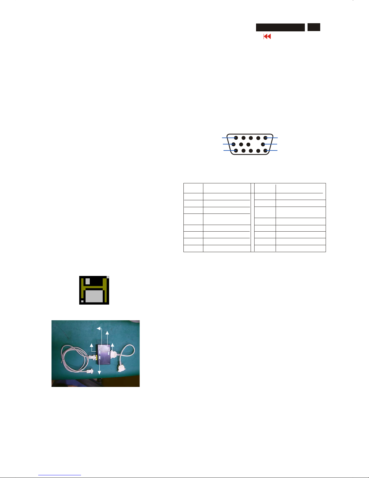
1. General
3. Pin assignment
Fig. 2 Alignment Kits
To Monitor
DC 8V~12V
Video Card
To Printer
Power indicator
A. 15-pin D-Sub Connector
DDC Data Re-programming
In case the main EEPROM with Software DDC which store all factory
settings were replaced because a defect,repaired monitor’ the serial
numbers have to be re-programmed.
It is advised to re-soldered the main EEPROM with Software DDC from
the old board onto the new board if circuit board have been replaced, in
this case the DDC data does not need to be re-programmed.
Additional information
Additional information about DDC (Display Data Channel) may be
obtained from Video Electronics Standards Association (VESA).
Extended Display Identification Data(EDID) information may be also
obtained from VESA.
DDC EDID structure
For the monitor : Standard Version 3.0
Structure Version 1.2
2. System and equipment requirements
1. An i486 (or above) personal computer or compatible.
2. Microsoft operation system Windows 95/98.
3. EDID301.EXE program (3138 106 10103) shown as Fig. 1
4. Software DDC Alignment kits (4822 310 11184) shown as Fig. 2.
The kit contents: a. Alignment box x1
b. Printer cable x1
c. D-Sub cable x1
Note: The EDID301.EXE (Release Version 1.58, 20000818)is a
windows-based program, which cannot be run in MS-DOS.
Diskette with EDID301.EXE
EDID301.EXE
Figure 1
Ver:1.58
The 15-pin D-sub connector (male) of the signal cable
on the 3rd row for DDC feature :
1
10
6
11
15
5
Assignment
Assignment
Pin No.
Pin No.
Ground
Ground
Blue video input
2
7
6
8
4
5
3
1
9
12
11
14
13
15
10
Red video ground
Blue video ground
Green video ground
for selftest(PC ground)
No pin
Sync. Ground
Data clock line(SCL)
V.Sync(VCLK)
H.Sync
Bi-directional data(SDA)
Green video input
Red video input
X
Go to cover page
24
DDC Instructions (Continued)
M32 107T4 GS_3
4. Configuration and procedure
There is no Hardware DDC (DDC IC) anymore. Main EEPROM stores
all factory settings and DDC data (EDID code) which is so called
Software DDC. The following section describes the connection and
procedure for Software DDC application. The main EEPROM can be reprobrammed by enabling "factory memory data write" function on the
DDC program (EDID301.EXE).
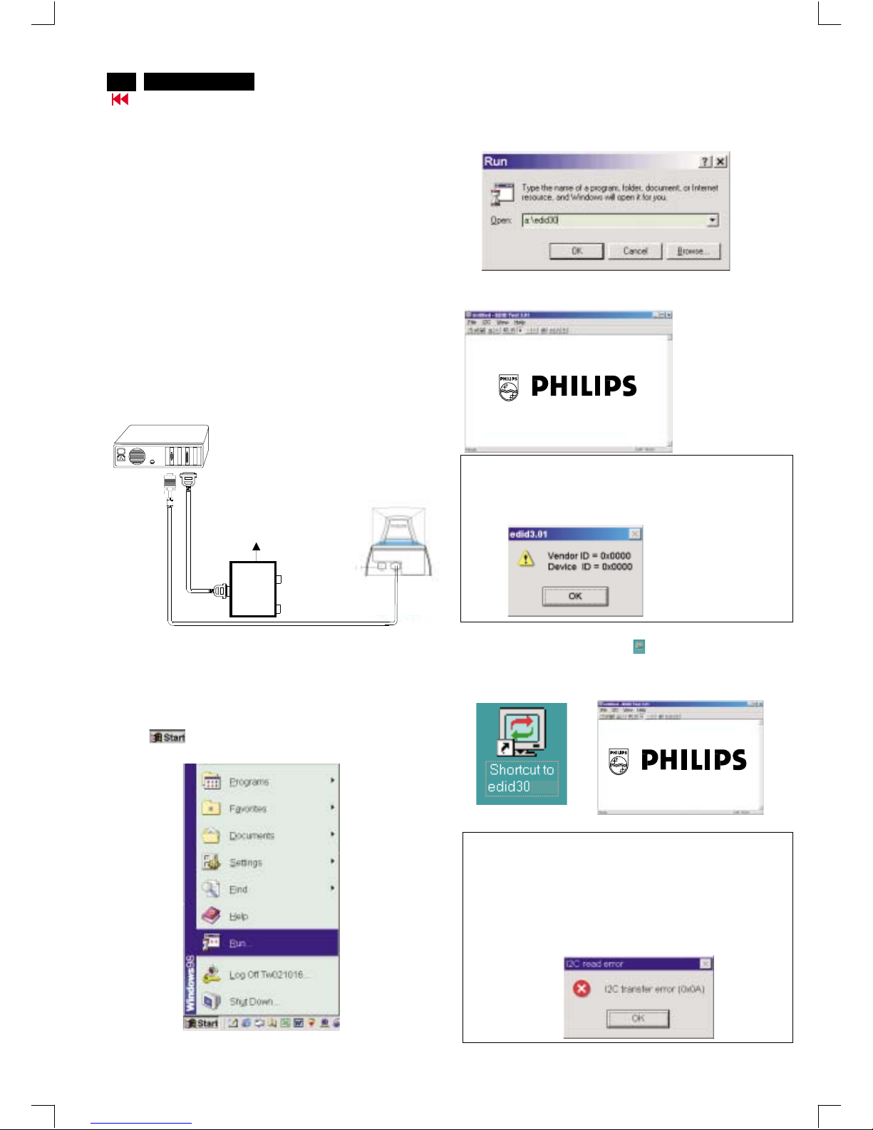
Step 3: Installation of EDID301.EXE
Method 1: Start on DDC program
Start Microsoft Windows.
1. Insert the disk containing EDID301.EXE program into floppy disk
drive.
2. Click , choose Run at start menu of Windows 95/98 as
shown in Fig. 4.
Fig. 4
*** INITIALIZE ALIGNMENT BOX ***
In order to avoid that monitor entering power saving mode due to
sync will cut off by alignment box, it is necessary to initialize
alignment box before re-programming DDC Data. Following steps
show you the procedures and connection.
Step 1
Step 2
: Supply 8~12V DC power source to the Alignment box by
plugging a DC power cord or using batteries.
: Connecting printer cable and video cable of monitor as
shown in Fig.3.
4. Click button. The main menu appears (as shown in Fig. 6).OK
This is for initialize alignment box.
Fig. 6
Fig. 5
Fig. 7
Note 1: If the connection is improper, you will see the following error
message (as shown in Fig. 7) before entering the main menu.
Meanwhile, the (read EDID) function will be disable. At this time,
please make sure all cables are connected correctly and fixedly,
and the procedure has been performed properly.
3. At the submenu, type the letter of your computer's floppy disk drive
followed by :EDID301 (for example, A:\EDID301, as shown in Fig. 5).
Method 2: After create a shortcut of EDID301.EXE
This is for initialize alignment box.
: Double click EDID301 icon (as shown in Fig. 8) which is
on the screen of Windows Wallpaper.
Bring up main menu of EDID301 as shown in Fig. 9.
Fig. 9
Note 2: During the loading, EDID301 will verify the EDID data which just
loaded from monitor before proceed any further function, once
the data structure of EDID can not be recognized, the following
error message will appear on the screen as below. Please
confirm following steps to avoid this message.
1. The data structure of EDID was incorrect.
2. DDC IC that you are trying to load data is empty.
3. Wrong communication channel has set at configuration setup
windows.
4. Cables loosed or poor contact of connection.
Fig. 8
1
Fig. 3
Rear view of the monitor
~
~
PC
To printer port (LTP1)
DC Power
8~12 V
Printer
Port
To video card
To
Monitor
To PC
Video cable
DDC Instructions (Continued)
Go to cover page
25
M32 107T4 GS_3
Fig. 13
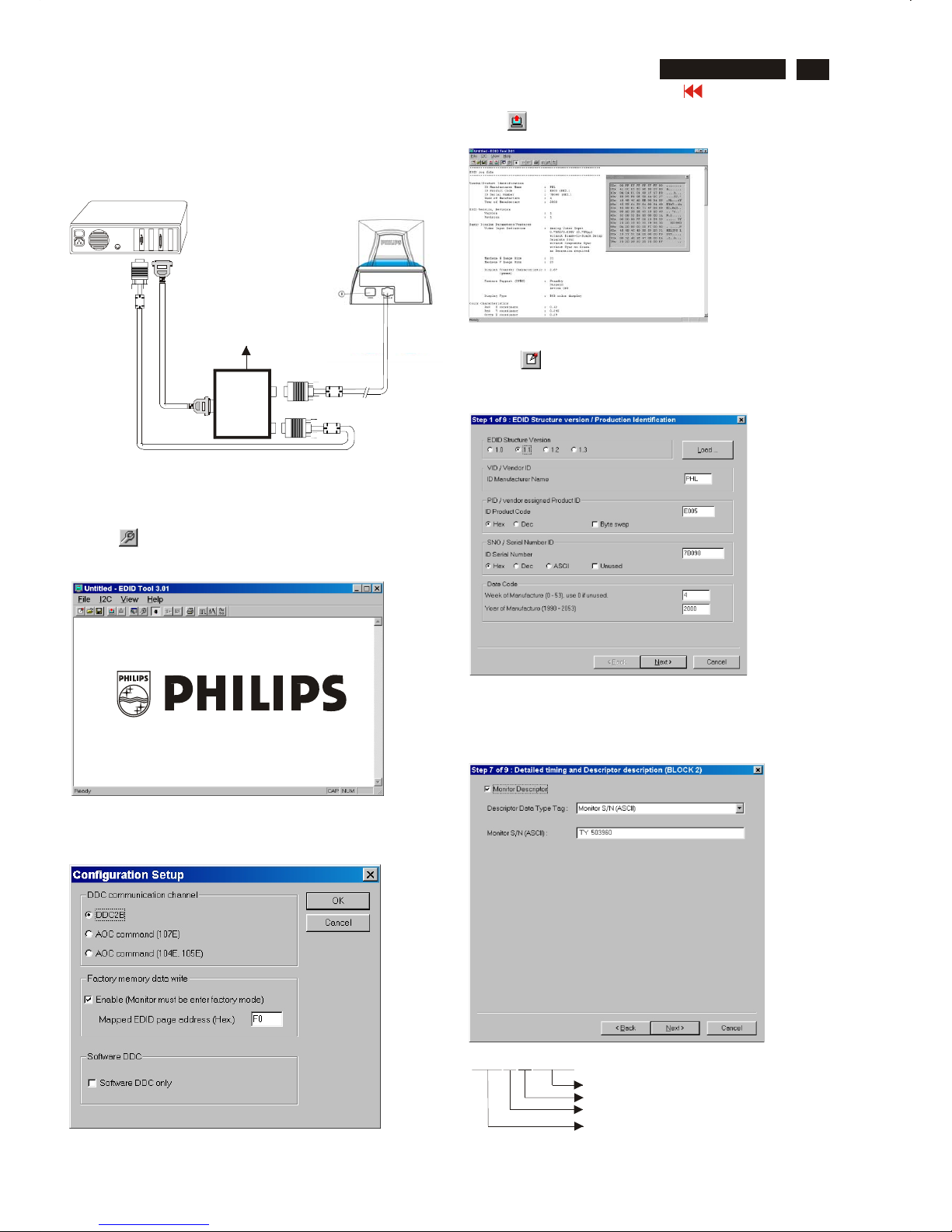
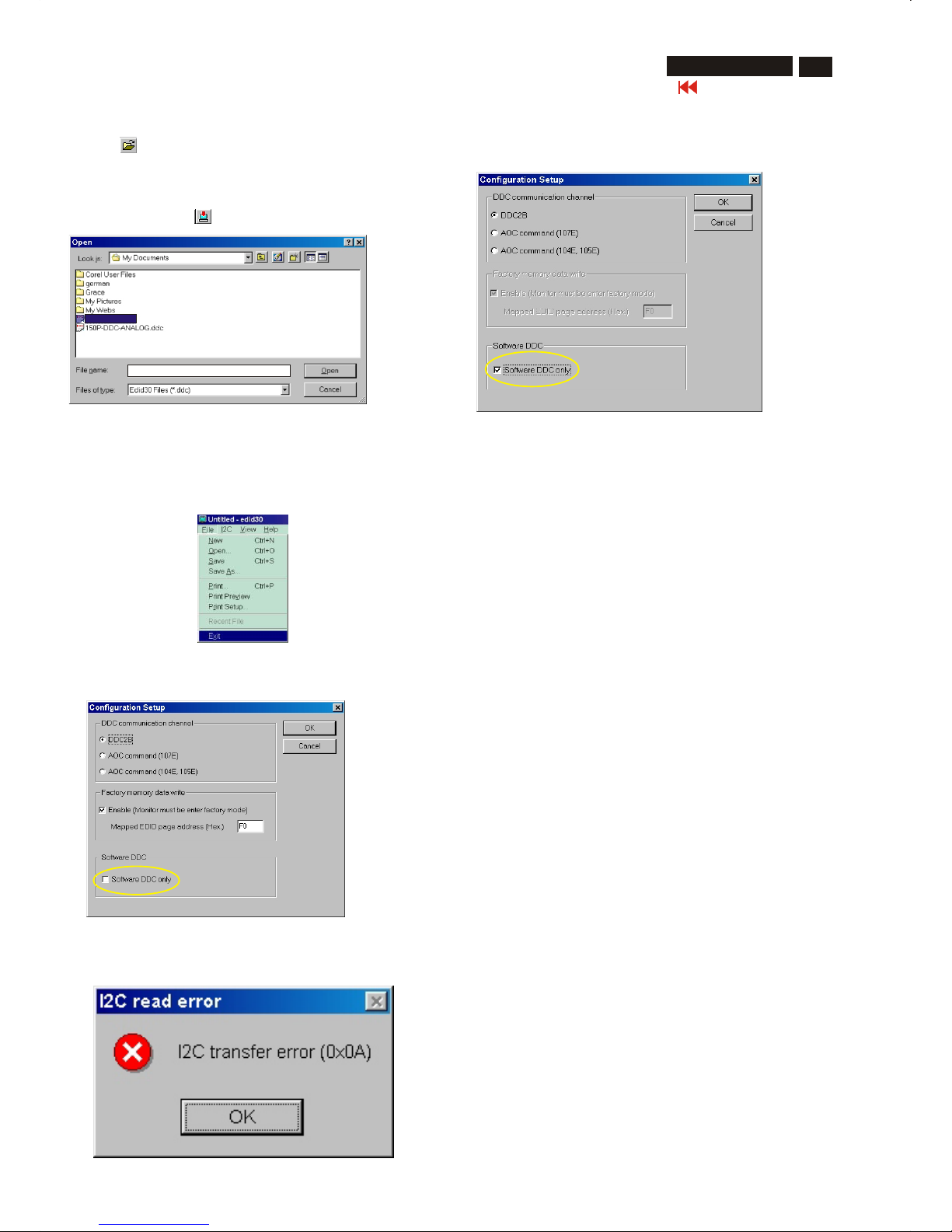
Re-programming EEPROM (Software DDC)
Step 1: After initialize alignment box, connecting all cables and
box as shown in Fig. 10
Fig. 11
Fig. 12
Step 2: Read DDC data from monitor
1-1 Click the left key of Mouse, or hit any key on the keyboard,
then the characters disappear from the screen.
1-2 Click icon as shown if Fig. 11 from the tool bar to bring up
the "Configuration Setup" windows as shown in Fig. 12.
2. Select the DDC2B as the communication channel.
Select "Enable" & fill out "F0" for Mapped EDID page address
as shown in Fig. 12.
Step 3: Modify DDC data (verify EDID version, week, year)
1. Click (new function) icon from the tool bar, bring up
Step 1 of 9 as shown in Fig. 14 .
EDID301 DDC application provides the function selection and
text change (select & fill out) from Step 1 to Step 9.
Step 4: Modify DDC data (Monitor Serial No.)
1. Click Next till the Step 7 of 9 window appears as shown in Fig. 15.
2. Fill out the new Serial No. (for example, TY 503960, TY 123456).
3. Click Next till the last step window appears, then click Finish to exit
the Step window.
3. Click OK button to confirm your selection.
4. Click icon (Read EDID function) to read DDC EDID data from
monitor. The EDID codes will display on screen as shown in Fig. 13.
Fig. 14
Fig. 15
~
~
PC
To video card
To printer port (LTP1)
DC Power
8~12 V
Printer
Port
To
Monitor
To PC
Video cable
Fig. 10
Rear view of the monitor
Definition of Serial Number (barcode format)
TY000028000001
Serial Number (U.S.A: 8 digit)
Week
Yea r
TY Code
TY----Chungli
CX----Dong Guan
HD----Hungary
BZ----Suzhou
(Others regions: 6 digit)
two space
(for example: change it from TY 503960
to TY 123456)
------>
DDC Instructions (Continued)
Go to cover page
26
M32 107T4 GS_3
Fig. 16
Fig. 18
Step 8: Save DDC data
Sometimes, you may need to save DDC data as a text file for using
in other IC chip. To save DDC data, follow the steps below:
1. Click (Save) icon (or click "file"-> "save as") from the tool bar
and give a file name as shown in Fig. 19.
The file type is EDID301 file (*.ddc) which can be open in WordPad.
By using WordPad, the texts of DDC data & table (128 bytes, hex
code) can be modified. If DDC TEXTS & HEX Table are completely
correct, it can be saved as .ddc flie to re-load it into EEPROM for
DDC Data application.
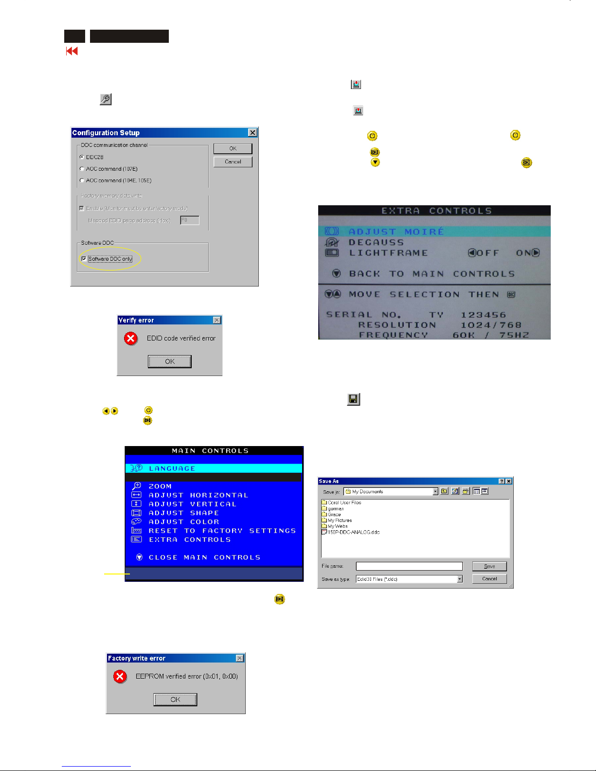
Step 5: **Configuration Setup & Enter Factory Mode **
for "write EDID data"
1. Click icon from the tool bar to bring up the Configuration Setup
windows again. Then, select "Software DDC only" as shown in
Fig. 16. Click "OK".
Step 6: Write DDC data
1. Click (Write EDID) icon from the tool bar to write DDC data.
Bring up "Writing 0%~100%, ready" a progressing bar on the left
down corner.
2. Click (Read EDID) to confirm it.
Step 7: Confirm Serial Number in User Mode
1. Press the button to turn off the monitor. Press the button
again to turn on the monitor.
2. Press the button to bring up the OSD Main Menu.
3. Press the button to select Extra Controls, press the
button to confirm your selection.
4. Confirm the Serial Number "123456" is updated
as shown in Fig. 18.
Fig. 19
If you do not select "Software DDC only", when you execute
"write EDID", it will bring up an error message as below.
If you do not access "Factory mode", when you execute
"write EDID", it will bring up an error message as below.
To access factory mode
1. Turn off monitor (don't turn off PC)
2. Press " " and " " simultaneously on the front control
panel,then press " ",wait till the OSD menu with characters
M32 107E/T4P V2.00 20020523 (below OSD menu)" come on the
screen of monitor.
If OSD menu disappears on the screen of monitor, press " "
again (anytime), then the OSD menu comes on the screen again.
Fig. 17
MODEL SELECT
M32 107E/T4P V2.00 20020523
Factory
Mode
Indicator
------------->
2. Click Save.
107T4_M32
DDC Instructions (Continued)
Go to cover page
27
M32 107T4 GS_3
Fig. 20
Fig. 22
Fig. 23
Fig. 21
Step 10: Exit DDC program
Pull down the File menu and select Exit as shown in Fig. 21.
(EDID Tool 3.01)
Step 9: Load DDC data
1. Click from the tool bar.
2. Select the file you want to open as shown in Fig. 20.
3. Click Open.
4. Access "Factory Mode" and enable "Software DDC only" as shown
in Fig. 17 & Fig. 16.
5. Write EDID (click ).
Note1 : In User Mode: Read DDC data only
Before read EDID code, please confirm that the Software
DDC only was disabled as shown in Fig. 22.
Note 2 : In Factory Mode: Read/Write DDC data
Before Read/Write EDID code, please confirm that the
Software DDC only was enabled as shown in Fig. 23.
If you do not disable "Software DDC only", when you execute
"read EDID", it will bring up an error message as below.
107T4_M32.DDC
107T4_M32.DDC
Electrical Adjustments
28
M32 107T4 GS_3
Go to cover page
0. General
5. To access factory mode
5.1 Turn off monitor (don't turn off PC)
5.2 Press " " and " " simultaneously on the front control
panel,then press " ",wait till the OSD menu with characters
M32 107E/T4P V2.00 20020523 (below OSD menu)" come on the
screen of monitor.
5.3 If OSD menu disappears on the screen of monitor, press " "
again (anytime), then the OSD menu comes on the screen again.
5.4 Using " " : to select OSD menu.
5.5 Using " " : to increase or decrease the setting.
5.6 Using " " to access/confirm the selection.
To leave factory mode
5.7 After alignment of factory mode, turn off monitor (if you do not
turn off monitor, the OSD menu is always at the factory mode),
then turn on monitor again (at this moment, the OSD menu goes
back to user mode).
When carry-out the electrical settings in many cases a video signal
must be applied to the monitor. A computer with :
- ATI GPT-1600 (4822 397 10065), Mach 64 (up to 107kHz)
are used as the video signal source. The signal patterns are selected
from the "service test software" package, see user guide 4822 727
21046 (GPT-1600).
0.1 This monitor has as below.8 factory-preset modes
720 x 400 31.5 kHz/70 Hz 1024 x 768 68.7 kHz/85 Hz
640 x 480 31.5 kHz/60 Hz
640 x 480 43.3 kHz/85 Hz
800 x 600 46.9 kHz/75 Hz
800 x 600 53.6 kHz/85 Hz
1024x768 60.0 kHz/75 Hz
1280 x 1024 64.0kHz/60Hz
14 factory-preload modes as below
640 x 350 31.5 kHz/70 Hz 800 x 600 48.1 kHz/72 Hz
640 x 350 37.9 kHz/85 Hz 800 x 600 63.9 kHz/100 Hz
640 x 480 37.5 kHz/75 Hz 832 x 624 49.7 kHz/75 Hz
640 x 480 37.9 kHz/72.8 Hz 1024 x 768 48.4 kHz/60 Hz
640 x 480 50.6 kHz/100 Hz 1024 x 768 56.5 kHz/70 Hz
720 x 400 37.9 kHz/85 Hz 1152 x 864 67.5 kHz/75 Hz
800 x 600 37.90kHz/60Hz 1280 x 960 60.0 kHz/60 Hz
1. With normal VGA card:
If not using the ATI card during repair or alignment, The service
engineer also can use this service test software adapting with normal
standard VGA adaptor and using standard VGA mode 640 x 480,
31.5 kHz/60 Hz (only) as signal source.
2. AC/DC Measurement:
The measurements for AC waveform and DC figure is based on 640 x
480 31.5 kHz/60 Hz resolution mode with test pattern "gray scale".
Power input: 110V AC
3.Monitor the following auxiliary voltages.
SOURCE ACROSS 7114 Pin and GRN +5 V +/- 0.25 VDC
SOURCE ACROSS C2155 +6.0 V +/- 0.2 VDC.
SOURCE ACROSS C2153 +12.0V +/- 1.0 VDC.
SOURCE ACROSS C2154 - 12.0V +/- 1.0 VDC.
SOURCE ACROSS C2151 +94.0V +/- 1.5 VDC.
SOURCE ACROSS C2609 - 181V +/- 10.0 VDC
6.1
Alignment of primary geometry
6.1.1
Apply Timing 7 (64KHz/60Hz, 1280x1024) with
black video signal, set
V-position at 50%, set H and V -
size for visible raster edges at all sides.
(RGB cut-
off can
be increased
temporarilytomake raster visible.
After
adjustment, restore RGB cut
off to original values.)
Slide
switch
1603
for centered raster in horizontal direction.
Adjust V
-
offset (I
2
C) for centered raster in vertical
direction.
Apply
Timing
8
(68.7kHz
/ 85Hz)
with
crosshatch signal and
start
geometry
alignment.
6.1.2 Adjust the Horizontal Size to 306mm.
6.1.3 Adjust the Horizontal Position for centered video.
6.1.4 Adjust the Vertical Size to 230 mm.
6.1.5 Adjust Vertical Position for centered video
6.1.6 Adjust picture tilt for correct TOP/BOTTOM lines.
(Picture tube should be mounted without tilt w.r.t. cabinet)
6.1.7 Adjust pincushion to get optimum vertical line.
6.1.8 Adjust trapezoid to get optimum vertical line.
6.1.9 Adjust balanced pincushion to get optimum vertical line.
6.1.10 Adjust the parallelogram to get optimum vertical line.
6.1.11
If needed, adjust the top / bottom corner control to
get optimum corner
geometry.
Top and bottom corner only affect top
and bottom 60mm of the vertical
lines.
(6.1.7, 6.1.8, 6.1.9 and 6.1.10 may need to be readjusted.)
6.1.12
Store the adjusted result and exit OS D.
(The values for pincushion, trapezoid, balance
pincushion and parallelogram
can be copied to
the other pre -
set modes to shorten alignment time.)
6.2 Other pre-set mode geometry adjustment
Use following procedure for all pre
-set modes
(except
68 .7kHz/85Hz)
(Timing Table 1 - 8)
6.2.1 Adjust the Horizontal Size to 306mm.
6.2.2 Adjust the Horizontal Position to center position.
6.2.3 Adjust the Vertical Size to 230 mm.
6.2.4 Adjust the Vertical Position for correctly ce ntred vertical video.
6.2.5 Adjust pincushion to get optimum vertical line.
6.2.6 Adjust trapezoid to get optimum vertical line.
6.2.7 Adjust balanced pincushion to get optimum vertical line.
6.2.8 Adjust the parallelogram to get optimum vertical line .
(6.2.5, 6.2.6, 6.2.7 and 6.2.8 may need some iteration.)
3.2.2
Store the set result and exit OSD.
6.3 Other pre -load modes can be visible inside the bezel.
SOURCE ACROSS C2152(+toGnd)+190 V +/- 2.0 VDC
4
General conditions for aging and alignment
4.1
Aging/burn
-
in:
Use low mains AC supply (90Vac) for monitor first
power on test.
Pre - adjust the Focus till cross hatch pattern can be
clearly visible then enter
the aging
mode. (Press bo
th
left and
right keysofbrightness
then switch-on the
monitor w/o signal
connected)
4.2
During all alignments, supply a distortion free AC mains
voltage
to set via
an isolating
transformer with low internal impedance.
4.3
All measurements are carried out at nominal mains voltage,
unless otherwise
stated.
4.4 Align in pre
-
warmed condition, at least 30 minutes warm
-
up with nominal
light output.
4.5
Purity, geometry and subsequent alignments should
be carried out in
magnetic cage
with correct magnetic field.
Northern Hemisphere: H = 0, V = 450 mG,Z=0
Southern Hemisphere: H = 0, V = -500 mG,Z=0
Equatorial Support : H = 0, V = 0 mG,Z=0
4.6
All volta
ges are to be measured or applied with
respect to ground , unless
otherwise stated. Attention
: Not all Heatsinksare
GND,
avoid using
heatsinks as ground.
4.7
The white balance and purity has to be adjusted
in dully lighted room.
4.8 All alignments have to be done in a room with a
temperature of 25 ± 10 °C.
MODEL SELECT
M32 107E/T4P V2.00 20020523
Factory
Mode
Indicator
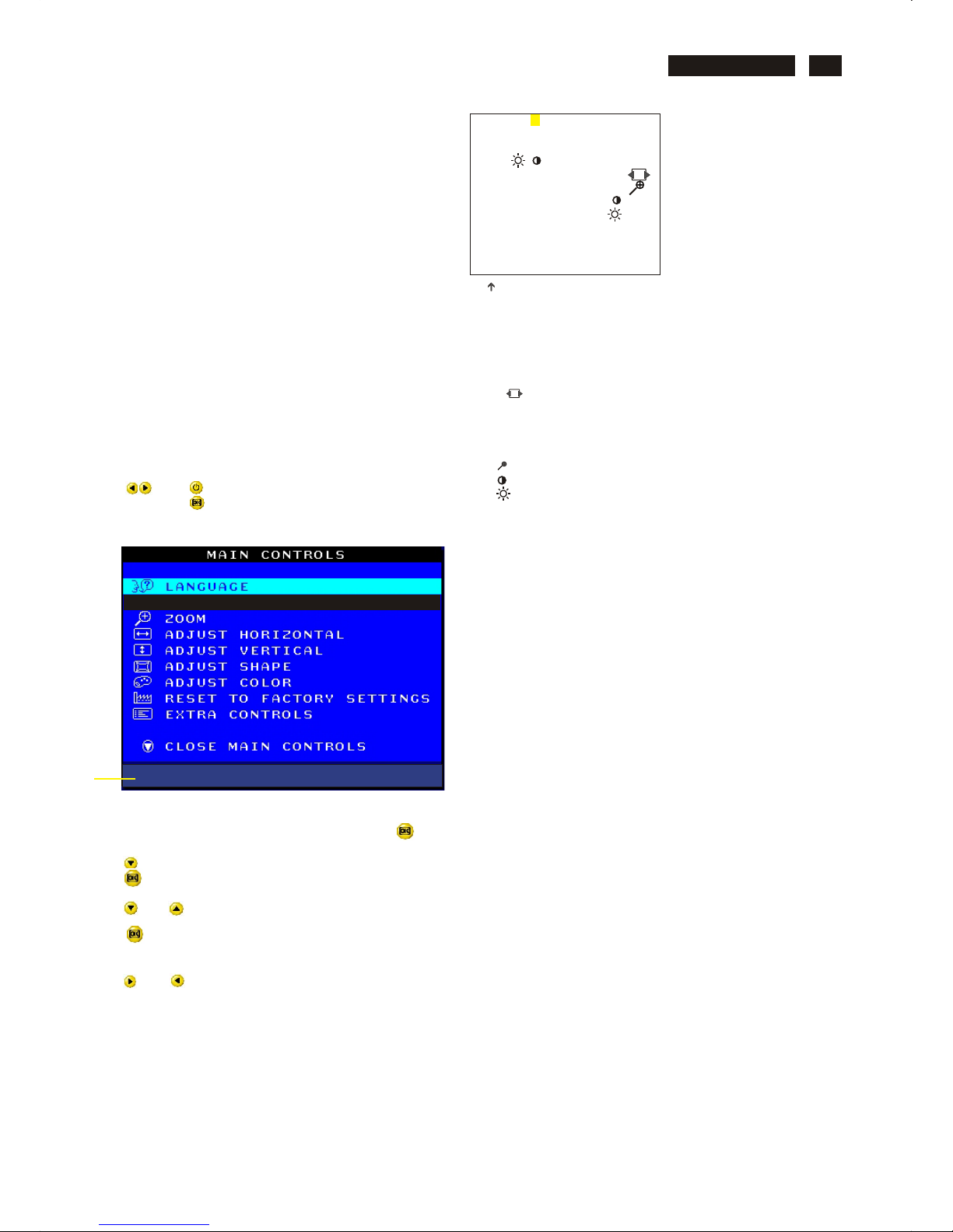
Electrical Adjustments (Continued)
Go to cover page
29
M32 107T4 GS_3
BIAS R G B : R(red) G(green) B(blue) cutoff
GAIN R G B : R(red) G(green) B(blue) gain
V FOCUS : Vertical Focus
VLIN BAL : Vertical Linearity Balance
USER : Horizontal size range
RASTER H: Horizontal DC (raster) Shift
RASTER V: Vertical DC (raster) Shift
HLIN : Horizontal Linearity
V LIN : Vertical Linearity
SUB : Zoom range
SUB : Sub Contrast
SUB : Sub Brigntness
V OFFSET : Vertical offset
V GAIN : Vertical Gain
ABL : Auto Beam Limit
T CORNER: Corner Correctionof TOP
B CORNER: Corner Correctionof BOTTOM
H (EHT REGU): Horizontal Extensive High Tension
LF : Light Frame
48K SUB : H-Size limit
7.2 Connect the video input, set brightness control at center, and
contrast control at maximum
7.3
set R,G,B cut-off at 127 9300k and 6500K(EEPROM preload value)
R,G,B gain at 185 9300k and
180 6500K(EEPROM preload value)
ABL at 160 9300k (EEPROM preload value)
SUB-CON at 220 9300k (EEPROM preload value)
7.4 Adjust 9300K color:
With color analyzer CA 100,
set R,G,B cut-off x=0.283, y=0.297, Y=0.10
7.5 Set R,G,B gain Y= 41+/- 1FL, x=0.283, y=0.297
7.6 Repeat 7.4,7.5 until RGB three guns get x=0.283, y=0.297,
readings on low Y=0.10+/-0.05FL and high Y=41+/-1FL
brightness of 9300.
7.7 Adjust 6500K color:
With color analyzer CA 100,
set R,G,B cut-off x=0.313, y=0.329, Y=0.10
7.8 Set R,G,B gain Y= 36+/- 1FL, x=0.313, y=0.329
7.9 Repeat 7.7,7.8 until RGB three guns get x=0.313, y=0.329,
readings on low Y=0.10+/-0.05FL and high Y=36+/-1FL
brightness of 6500.
7.10 Adjust SUB-CON to get Y=41+/-1FL.
7.11 Apply full white pattern of 9300 mode, adjust ABL to reach
30 +/- 1FL(at 9300 high brightness of R/G/B gain,
contrast at 100%)
( for ref. 152, 38,71,242,202,226)
(for ref. 160,41,75,238,174,153)
( for ref. 0,120,95,70)
(for ref. 127,127,255,41,80)
( for ref. 170,170,220)
(for ref. 70,65,152,255)
( for ref. 183,152)
(for ref. 96,96)
( for ref. 4,4)
(for ref. 230)
Fig. 2.2
(for example: 152 is value of "BIAS R")
7. Alignment of Vg2 cut-off point, white tracking
Equipment : 1. Video Test Generator-801GC (Quantum Data)
2. Color-analyzer (Minolta CA-100)
VG2 [(screen), at the bottom of the L.O.T.].
7.1 Apply a video signal in the 1024 x 768 with 68.7 kHz/85 Hz mode,
select the "full white pattern" (sizes 306 x 230 mm).
* Use color-analyzer (Minolta CA-100) to adjust R/G/B cutoff and
gain.
OSD R/G/B cut-off and R/G/B gain can be accessed (for Philips
CRT), with initial data:
o
9300 K
2
R cutoff = 50%, R gain = 73% (I C)
2
G cutoff = 50%, G gain = 73% (I C)
2
B cutoff = 50%, B gain = 73% (I C)
o
6500 K
2
R cutoff = 50%, R gain = 71% (I C)
2
G cutoff = 50%, G gain = 71% (I C)
2
B cutoff = 50%, B gain = 71% (I C)
2
Brightness = 50%, Sub-Contrast = 86%, ABL = 63% (I C)
Step 1: To access factory mode
- Turn off monitor (don't turn off PC)
- Press " " and " " simultaneously on the front control
panel,then press " ",wait till the OSD menu with characters
M32 107E/T4P V2.00 20020523 (below OSD menu)" comes on
the screen of monitor as shown in Fig. 2.1.
- If OSD menu disappears on the screen of monitor, press " "
again (anytime), then the OSD menu comes on the screen again.
- Using " " to select .
- Using " " or " " : to increase or decrease the value.
“ M32 107E/T4P V2.00 20020523
- Press " " button to access/confirm the selection.
Bring up the "function adjustment" as shown in Fig. 2.2.
- Press " " or " " button for function selection as shown in
Fig. 2.2.
- Press " " button to access/confirm each item selection
(The cursor indicator will be changed from yellow colour to
red colour.)
MODEL SELECT
Factory
Mode
Indicator
Fig. 2.1
9300 BIAS R G B GAIN R G B
6500 BIAS R G B GAIN R G B
SRGB BIAS R G B GAIN R G B
SRGB ( )
FOCUS(H V) VLINBAL USER
RASTER(H V) LIN ( H V ) SUB
V(OFFSET GAIN) SUB
CORNER(T B) ABL SUB
BPLUS ( EHT REGU)
LF (BRIGH SHARP)
48K SUB
EXIT
152
152
M32 107E/T4P V2.00 20020523
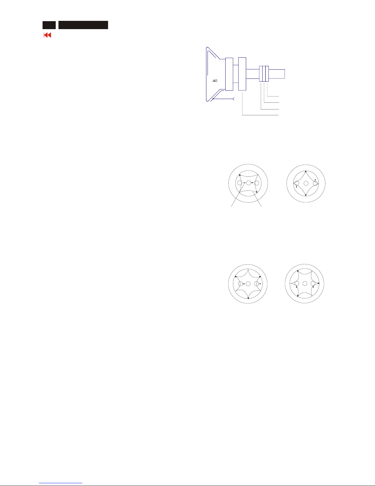
8. Focus adjustment
Apply a signal of " @ " character. at 68.7 kHz/85 Hz mode set the
brightness to mid-position , contrast to max - position and adjust
the focus for optimal sharpness in the area within 2/3 from the
screen center.
9. Loading DDC code
The DDC HEX data should be written into the EEPROM
(7803) by EDID301.EXE Program(3138 106 10103)
and software DDC Alignment kits (4822 310 11184).
10. Purity adjustment
- Make sure the monitor is not exposed to any
external magnetic field.
- Produce a full red pattern on the screen, adjust the
purity magnet rings on the PCM assy (on CRT) to
obtain a complete field of the color red. This is done
by moving the two tabs (2-pole) in such a manner
that they advance in an opposite direction but at
the same time to obtain the same angle between
the two tabs, which should be approximately 180
degree.
- Check by full green pattern and full blue pattern
again to observe their respective color purity.
11. Static convergence
Introduction
Slight deviation in the static convergence can be
corrected by using two permanent pairs of magnets
which are fitted around the neck of the CRT. These
are the 4-pole magnet and the 6-pole magnet.
The 4-pole magnet move the outermost electron
beams (R and B) parallel in the opposite direction
from the other. The 6-pole magnet moves the
outermost electron beam (R, B and G) parallel in the
opposite direction from the other.
The magnetic field of the above magnets do not affect
the center of the CRT neck.
Setting
- Before the static convergence setting can be made,
the monitor must be switched on for 30 minutes.
- The focus setting must be made correctly.
- Signal: 640 * 480, 31.5 kHz/60 Hz mode.
- Set the tabs of the 4-pole magnet in the neutral
position. This is when the tabs are opposite one
another. In this position the magnets do not affect the
deflection of the R and B electron beams.
- Set the tabs of the 6-pole magnet in the neutral
position. This is when the tabs are opposite one
another. In this position the magnets do not affect the
deflection of the R, B, and G electron beams.
- First set the 4-pole magnet optimally.
- Then set the 6-pole magnet optimally.
- If the convergence is not now optimal, then adjust to
the optimal setting with the 4-pole magnet and then with
the 6- Pole magnet again.
- Set the tabs of the 6-pole magnet in the neutral
position. This is when the tabs are opposite one
another. In this position the magnets do not affect the
deflection of the R, B, and G electron beams.
- First set the 4-pole magnet optimally.
- Then set the 6-pole magnet optimally.
- If the convergence is not now optimal, then adjust to
the optimal setting with the 4-pole magnet and then
with the 6- pole magnet again.
2-pole purity magnet
6-pole convergence magnet
4-pole convergence magnet
Deflection Yoke
4-pole Beam motion producced by the
4-pole convergence magnet
S
S
N
N
B
G R
S
S
N
N
B
G
R
Beam displacement
direction
Magnetic flux
lines
6-pole
Beam motion producced by the
6- pole convergence magnet
S
S
S
N
N
N
R
B
G
S
S
S
N
N
N
R
B
G
Electrical Adjustments (Continued)
Go to cover page
30
M32 107T4 GS_3
 Loading...