

Page 1

Series 50 Fetal Monitors
Series 50 A (M1351A)
Series 50 IP-2 (M1353A)
SERVICE AND INSTALLATION GUIDE
M1353-9000J
Printed in Germany April 2002
Page 2

Notice
Philips makes no warranty of any kind with regard to this material, including, but
not limited to, the implied warranties of merchantability and fitness for a particular
purpose. Philips Medical Systems shall not be liable for errors contained herein or for
incidental or consequential dam age s in co nn ect ion w ith the fu rni shi ng, pe rforman ce
or use of this material.
This document contains proprietary information that is protected by copyright. All
rights are reserved. No part of this document may be photocopied, reproduced or
translated to another language without prior written consent of Philips Medical
Systems.
The information contained in this document is subject to change without notice.
Philips assumes no responsibility for the use or reliability of its software on
equipment that is not fu rnished by Philips.
Purchase of this instrument confers no express or implied license under any Nellcor
patent or copyright to use this instrument with any fetal oximetry sensor that is not
manufactured or licensed by Nellcor.
Dinamap is a trademark of General Electric.
Press-Mate is a trademark of the COLIN Corporation.
Federal Law (US) restricts this device to sale by or on the order of a physician.
Caution
Failure on the part of the responsi ble individual hospital or institution
employing the use of this equipment to implement a satisfactory
maintenance schedule may cause und u e equipment failure and possible
health hazards.
Page 3

Printing History
New editions are complete revisions of the manual. Update packages, which are issued
between editions, contain additional and replacement page s to be add ed t o t he manual . Th e
dates on the title page ch a nge only when a new edition or a new update is published.
Edition 1: June 1992
Edition 2: A ugust 1993
Edition 3: February 1995
Edition 4: March 1997
Edition 5: February 1998
Edition 6: May 2000
Edition 7: Apri l 2002
2002 Philips Medizinsysteme Böblingen GmbH
All rights are reserved. Reproduction in wh ole or in part is prohibited without the prior
written consent of the copyright holder.
Page 4

Page 5

Contents
1. General Information . . . . . . . . . . . . . . . . . . . . . . . . . . . . . . . . . . . . . . . . . . . . . . . . . . . . . . . . 1
Introduction. . . . . . . . . . . . . . . . . . . . . . . . . . . . . . . . . . . . . . . . . . . . . . . . . . . . . . . . . . . . . . . . . . . . . . . . . . . . . . .1
Who Should Read This Guide. . . . . . . . . . . . . . . . . . . . . . . . . . . . . . . . . . . . . . . . . . . . . . . . . . . . . . . . . . . . .1
What to do Next. . . . . . . . . . . . . . . . . . . . . . . . . . . . . . . . . . . . . . . . . . . . . . . . . . . . . . . . . . . . . . . . . . . . . . . .1
Repair Strategy . . . . . . . . . . . . . . . . . . . . . . . . . . . . . . . . . . . . . . . . . . . . . . . . . . . . . . . . . . . . . . . . . . . . . . . . . . . .1
Conventions and Symbols Used in this Guide . . . . . . . . . . . . . . . . . . . . . . . . . . . . . . . . . . . . . . . . . . . . . . . . . . . .2
Initial Inspection . . . . . . . . . . . . . . . . . . . . . . . . . . . . . . . . . . . . . . . . . . . . . . . . . . . . . . . . . . . . . . . . . . . . . . . . . . .3
Claims for Damage . . . . . . . . . . . . . . . . . . . . . . . . . . . . . . . . . . . . . . . . . . . . . . . . . . . . . . . . . . . . . . . . . . . . . 3
Repacking . . . . . . . . . . . . . . . . . . . . . . . . . . . . . . . . . . . . . . . . . . . . . . . . . . . . . . . . . . . . . . . . . . . . . . . . . . . .3
Overview . . . . . . . . . . . . . . . . . . . . . . . . . . . . . . . . . . . . . . . . . . . . . . . . . . . . . . . . . . . . . . . . . . . . . . . . . . . . . . . .4
Major Keys and Parts at a Glance. . . . . . . . . . . . . . . . . . . . . . . . . . . . . . . . . . . . . . . . . . . . . . . . . . . . . . . . . . . . . . 5
Monitor Control and Display Panel . . . . . . . . . . . . . . . . . . . . . . . . . . . . . . . . . . . . . . . . . . . . . . . . . . . . . . . . . . . .7
M1351A Single Ultrasound Model . . . . . . . . . . . . . . . . . . . . . . . . . . . . . . . . . . . . . . . . . . . . . . . . . . . . . . . .7
M1351A Dual Ultrasound Twins Model. . . . . . . . . . . . . . . . . . . . . . . . . . . . . . . . . . . . . . . . . . . . . . . . . . . . .7
M1353A Model . . . . . . . . . . . . . . . . . . . . . . . . . . . . . . . . . . . . . . . . . . . . . . . . . . . . . . . . . . . . . . . . . . . . . . .8
Accessories . . . . . . . . . . . . . . . . . . . . . . . . . . . . . . . . . . . . . . . . . . . . . . . . . . . . . . . . . . . . . . . . . . . . . . . . . . . . . . .9
Series 50 A (M1351A). . . . . . . . . . . . . . . . . . . . . . . . . . . . . . . . . . . . . . . . . . . . . . . . . . . . . . . . . . . . . . . . . . . 9
Series 50 IP-2 (M1353A). . . . . . . . . . . . . . . . . . . . . . . . . . . . . . . . . . . . . . . . . . . . . . . . . . . . . . . . . . . . . . . . . 9
Documentation. . . . . . . . . . . . . . . . . . . . . . . . . . . . . . . . . . . . . . . . . . . . . . . . . . . . . . . . . . . . . . . . . . . . . . . . 10
Options. . . . . . . . . . . . . . . . . . . . . . . . . . . . . . . . . . . . . . . . . . . . . . . . . . . . . . . . . . . . . . . . . . . . . . . . . . . . . . 11
2. Technical Specifications . . . . . . . . . . . . . . . . . . . . . . . . . . . . . . . . . . . . . . . . . . . . . . . . . . . . 13
Monitor . . . . . . . . . . . . . . . . . . . . . . . . . . . . . . . . . . . . . . . . . . . . . . . . . . . . . . . . . . . . . . . . . . . . . . . . . . . . . . . . .13
Power Requirements . . . . . . . . . . . . . . . . . . . . . . . . . . . . . . . . . . . . . . . . . . . . . . . . . . . . . . . . . . . . . . . . . . . 13
Environment. . . . . . . . . . . . . . . . . . . . . . . . . . . . . . . . . . . . . . . . . . . . . . . . . . . . . . . . . . . . . . . . . . . . . . . . . . 13
Weight and Dimensions. . . . . . . . . . . . . . . . . . . . . . . . . . . . . . . . . . . . . . . . . . . . . . . . . . . . . . . . . . . . . . . . .13
Displays . . . . . . . . . . . . . . . . . . . . . . . . . . . . . . . . . . . . . . . . . . . . . . . . . . . . . . . . . . . . . . . . . . . . . . . . . . . . . 14
Inputs . . . . . . . . . . . . . . . . . . . . . . . . . . . . . . . . . . . . . . . . . . . . . . . . . . . . . . . . . . . . . . . . . . . . . . . . . . . . . . .14
Recorder. . . . . . . . . . . . . . . . . . . . . . . . . . . . . . . . . . . . . . . . . . . . . . . . . . . . . . . . . . . . . . . . . . . . . . . . . . . . . 15
Self-Test Facilities . . . . . . . . . . . . . . . . . . . . . . . . . . . . . . . . . . . . . . . . . . . . . . . . . . . . . . . . . . . . . . . . . . . . .16
Combined Interface Module . . . . . . . . . . . . . . . . . . . . . . . . . . . . . . . . . . . . . . . . . . . . . . . . . . . . . . . . . . . . .16
Modem Interface Module . . . . . . . . . . . . . . . . . . . . . . . . . . . . . . . . . . . . . . . . . . . . . . . . . . . . . . . . . . . . . . . 16
Remote Event Marker (15249A) . . . . . . . . . . . . . . . . . . . . . . . . . . . . . . . . . . . . . . . . . . . . . . . . . . . . . . . . . . 16
Transducers and Cables. . . . . . . . . . . . . . . . . . . . . . . . . . . . . . . . . . . . . . . . . . . . . . . . . . . . . . . . . . . . . . . . . . . . .17
Brown Toco Transducer (M1355A) . . . . . . . . . . . . . . . . . . . . . . . . . . . . . . . . . . . . . . . . . . . . . . . . . . . . . . . 17
Blue Toco Transducer (M1355A) . . . . . . . . . . . . . . . . . . . . . . . . . . . . . . . . . . . . . . . . . . . . . . . . . . . . . . . . . 17
Brown Ultrasound Transducer (M1356A). . . . . . . . . . . . . . . . . . . . . . . . . . . . . . . . . . . . . . . . . . . . . . . . . . . 17
1
Blue
Ultrasound Transducer (M1356A) . . . . . . . . . . . . . . . . . . . . . . . . . . . . . . . . . . . . . . . . . . . . . . . . . . . 17
DECG Transducer (M1357A) . . . . . . . . . . . . . . . . . . . . . . . . . . . . . . . . . . . . . . . . . . . . . . . . . . . . . . . . . . . . 18
MECG Transducer (M1359A). . . . . . . . . . . . . . . . . . . . . . . . . . . . . . . . . . . . . . . . . . . . . . . . . . . . . . . . . . . .18
DECG/MECG Patient Module (M1364A) . . . . . . . . . . . . . . . . . . . . . . . . . . . . . . . . . . . . . . . . . . . . . . . . . .18
IUP Quartz Transducer (1290C option J05) . . . . . . . . . . . . . . . . . . . . . . . . . . . . . . . . . . . . . . . . . . . . . . . . . 19
IUP Pressure Transducer (CPJ840J5) . . . . . . . . . . . . . . . . . . . . . . . . . . . . . . . . . . . . . . . . . . . . . . . . . . . . . . 20
3. Installing the Monitor . . . . . . . . . . . . . . . . . . . . . . . . . . . . . . . . . . . . . . . . . . . . . . . . . . . . . . 21
Fitting the Monitor to a Surface . . . . . . . . . . . . . . . . . . . . . . . . . . . . . . . . . . . . . . . . . . . . . . . . . . . . . . . . . . . . . .21
Contents v
Page 6

Fitting the Monitor to the Angle Mount. . . . . . . . . . . . . . . . . . . . . . . . . . . . . . . . . . . . . . . . . . . . . . . . . . . . . . . . 21
Fitting the Monitor to a Wall . . . . . . . . . . . . . . . . . . . . . . . . . . . . . . . . . . . . . . . . . . . . . . . . . . . . . . . . . . . . . . . . 22
Wall Mount Dimensions . . . . . . . . . . . . . . . . . . . . . . . . . . . . . . . . . . . . . . . . . . . . . . . . . . . . . . . . . . . . . . . . 22
Fitting the Paper Take-Up Tray . . . . . . . . . . . . . . . . . . . . . . . . . . . . . . . . . . . . . . . . . . . . . . . . . . . . . . . . . . . . . .23
Cart-mounted Paper Tray . . . . . . . . . . . . . . . . . . . . . . . . . . . . . . . . . . . . . . . . . . . . . . . . . . . . . . . . . . . . . . . 23
Carts . . . . . . . . . . . . . . . . . . . . . . . . . . . . . . . . . . . . . . . . . . . . . . . . . . . . . . . . . . . . . . . . . . . . . . . . . . . . . . . . . . .24
Fitting the Barcode Reader Holder . . . . . . . . . . . . . . . . . . . . . . . . . . . . . . . . . . . . . . . . . . . . . . . . . . . . . . . . . . . 24
4. Configuring the Monitor. . . . . . . . . . . . . . . . . . . . . . . . . . . . . . . . . . . . . . . . . . . . . . . . . . . . .25
Introduction . . . . . . . . . . . . . . . . . . . . . . . . . . . . . . . . . . . . . . . . . . . . . . . . . . . . . . . . . . . . . . . . . . . . . . . . . . . . . 25
Configuring the Monitor Using Pushbuttons . . . . . . . . . . . . . . . . . . . . . . . . . . . . . . . . . . . . . . . . . . . . . . . . . . . . 26
Examples: How to Change the Time Format and IUP Format using Pushbuttons. . . . . . . . . . . . . . . . . . . . 28
Configuring the Monitor Using Barcodes . . . . . . . . . . . . . . . . . . . . . . . . . . . . . . . . . . . . . . . . . . . . . . . . . . . . . . 29
Configuring the Monitor Using a PC . . . . . . . . . . . . . . . . . . . . . . . . . . . . . . . . . . . . . . . . . . . . . . . . . . . . . . . . . .29
Installing the Service Program . . . . . . . . . . . . . . . . . . . . . . . . . . . . . . . . . . . . . . . . . . . . . . . . . . . . . . . . . . . 30
Connecting the PC to the Monitor. . . . . . . . . . . . . . . . . . . . . . . . . . . . . . . . . . . . . . . . . . . . . . . . . . . . . . . . . 31
Loading the Service Program . . . . . . . . . . . . . . . . . . . . . . . . . . . . . . . . . . . . . . . . . . . . . . . . . . . . . . . . . . . . 31
Using the Service Program . . . . . . . . . . . . . . . . . . . . . . . . . . . . . . . . . . . . . . . . . . . . . . . . . . . . . . . . . . . . . . 31
Error Log Messages . . . . . . . . . . . . . . . . . . . . . . . . . . . . . . . . . . . . . . . . . . . . . . . . . . . . . . . . . . . . . . . . . . . . . . . 44
5. Setting Time, Date, and Paper Speed. . . . . . . . . . . . . . . . . . . . . . . . . . . . . . . . . . . . . . . . . . .47
Time and Date . . . . . . . . . . . . . . . . . . . . . . . . . . . . . . . . . . . . . . . . . . . . . . . . . . . . . . . . . . . . . . . . . . . . . . . . . . . 47
Paper Speed . . . . . . . . . . . . . . . . . . . . . . . . . . . . . . . . . . . . . . . . . . . . . . . . . . . . . . . . . . . . . . . . . . . . . . . . . . . . .48
6. Theory of Operation . . . . . . . . . . . . . . . . . . . . . . . . . . . . . . . . . . . . . . . . . . . . . . . . . . . . . . . .49
System Overview . . . . . . . . . . . . . . . . . . . . . . . . . . . . . . . . . . . . . . . . . . . . . . . . . . . . . . . . . . . . . . . . . . . . . . . . .49
Booting and Self Tests . . . . . . . . . . . . . . . . . . . . . . . . . . . . . . . . . . . . . . . . . . . . . . . . . . . . . . . . . . . . . . . . . . . . .50
Front End Board . . . . . . . . . . . . . . . . . . . . . . . . . . . . . . . . . . . . . . . . . . . . . . . . . . . . . . . . . . . . . . . . . . . . . . . . . .52
M1351A (M1353-66501 and M1353-66511) . . . . . . . . . . . . . . . . . . . . . . . . . . . . . . . . . . . . . . . . . . . . . . 52
M1353A (M1353-66512) . . . . . . . . . . . . . . . . . . . . . . . . . . . . . . . . . . . . . . . . . . . . . . . . . . . . . . . . . . . . . . . 52
Frontend Board for M1353A (M1350-66517) . . . . . . . . . . . . . . . . . . . . . . . . . . . . . . . . . . . . . . . . . . . . . . . 54
Power Supply Board (M1353-66502) . . . . . . . . . . . . . . . . . . . . . . . . . . . . . . . . . . . . . . . . . . . . . . . . . . . . . . . . . 55
CPU Board (M1353-66503 and M1353-66513) . . . . . . . . . . . . . . . . . . . . . . . . . . . . . . . . . . . . . . . . . . . . . . . . .56
CPU Board M1353-66503. . . . . . . . . . . . . . . . . . . . . . . . . . . . . . . . . . . . . . . . . . . . . . . . . . . . . . . . . . . . . . . 56
CPU Board M1353-66513. . . . . . . . . . . . . . . . . . . . . . . . . . . . . . . . . . . . . . . . . . . . . . . . . . . . . . . . . . . . . . . 56
Display Board (M1350-66520) . . . . . . . . . . . . . . . . . . . . . . . . . . . . . . . . . . . . . . . . . . . . . . . . . . . . . . . . . . . . . . 58
Recorder Interface Board (M1353-66510) . . . . . . . . . . . . . . . . . . . . . . . . . . . . . . . . . . . . . . . . . . . . . . . . . . . . . 59
Interface Boards . . . . . . . . . . . . . . . . . . . . . . . . . . . . . . . . . . . . . . . . . . . . . . . . . . . . . . . . . . . . . . . . . . . . . . . .60
Combined Interface Board . . . . . . . . . . . . . . . . . . . . . . . . . . . . . . . . . . . . . . . . . . . . . . . . . . . . . . . . . . . . . . 60
Modem Interface Board. . . . . . . . . . . . . . . . . . . . . . . . . . . . . . . . . . . . . . . . . . . . . . . . . . . . . . . . . . . . . . . . . 63
7. Tests and Error Messages. . . . . . . . . . . . . . . . . . . . . . . . . . . . . . . . . . . . . . . . . . . . . . . . . . . .65
Service Philosophy. . . . . . . . . . . . . . . . . . . . . . . . . . . . . . . . . . . . . . . . . . . . . . . . . . . . . . . . . . . . . . . . . . . . . . . . 65
Overview of the Service Tests. . . . . . . . . . . . . . . . . . . . . . . . . . . . . . . . . . . . . . . . . . . . . . . . . . . . . . . . . . . . 65
Performance Assurance Tests. . . . . . . . . . . . . . . . . . . . . . . . . . . . . . . . . . . . . . . . . . . . . . . . . . . . . . . . . . . . . . . . 65
Self Test. . . . . . . . . . . . . . . . . . . . . . . . . . . . . . . . . . . . . . . . . . . . . . . . . . . . . . . . . . . . . . . . . . . . . . . . . . . . . 65
Quick Test . . . . . . . . . . . . . . . . . . . . . . . . . . . . . . . . . . . . . . . . . . . . . . . . . . . . . . . . . . . . . . . . . . . . . . . . . . . 66
Parameter Test. . . . . . . . . . . . . . . . . . . . . . . . . . . . . . . . . . . . . . . . . . . . . . . . . . . . . . . . . . . . . . . . . . . . . . . . 68
Operator Error Messages . . . . . . . . . . . . . . . . . . . . . . . . . . . . . . . . . . . . . . . . . . . . . . . . . . . . . . . . . . . . . . . . . . . 69
Permanent Test. . . . . . . . . . . . . . . . . . . . . . . . . . . . . . . . . . . . . . . . . . . . . . . . . . . . . . . . . . . . . . . . . . . . . . . . . . . 70
FSpO2. . . . . . . . . . . . . . . . . . . . . . . . . . . . . . . . . . . . . . . . . . . . . . . . . . . . . . . . . . . . . . . . . . . . . . . . . . . . . . . . . . 70
8. Troubleshooting Flowcharts . . . . . . . . . . . . . . . . . . . . . . . . . . . . . . . . . . . . . . . . . . . . . . . . .71
vi Contents
Page 7

Introduction. . . . . . . . . . . . . . . . . . . . . . . . . . . . . . . . . . . . . . . . . . . . . . . . . . . . . . . . . . . . . . . . . . . . . . . . . . . . . .71
Error 500: General Failure . . . . . . . . . . . . . . . . . . . . . . . . . . . . . . . . . . . . . . . . . . . . . . . . . . . . . . . . . . . . . . . . . .72
Error 501, 511, 512, 516, 517: Front End Board . . . . . . . . . . . . . . . . . . . . . . . . . . . . . . . . . . . . . . . . . . . . . . . . . 74
Error 502: Power Supply. . . . . . . . . . . . . . . . . . . . . . . . . . . . . . . . . . . . . . . . . . . . . . . . . . . . . . . . . . . . . . . . . . . .76
Error 503 and 513: CPU Board. . . . . . . . . . . . . . . . . . . . . . . . . . . . . . . . . . . . . . . . . . . . . . . . . . . . . . . . . . . . . . .78
Error 510: Recorder Board . . . . . . . . . . . . . . . . . . . . . . . . . . . . . . . . . . . . . . . . . . . . . . . . . . . . . . . . . . . . . . . . . .79
Error 531: Combined Interface Board. . . . . . . . . . . . . . . . . . . . . . . . . . . . . . . . . . . . . . . . . . . . . . . . . . . . . . . . . .80
Error 532: Modem Interface Board. . . . . . . . . . . . . . . . . . . . . . . . . . . . . . . . . . . . . . . . . . . . . . . . . . . . . . . . . . . .81
Error 70: Modem Not Responding . . . . . . . . . . . . . . . . . . . . . . . . . . . . . . . . . . . . . . . . . . . . . . . . . . . . . . . . . . . .82
Error 77: Modem Transmission Failure . . . . . . . . . . . . . . . . . . . . . . . . . . . . . . . . . . . . . . . . . . . . . . . . . . . . . . . .83
Error 601: Paper Feed. . . . . . . . . . . . . . . . . . . . . . . . . . . . . . . . . . . . . . . . . . . . . . . . . . . . . . . . . . . . . . . . . . . . . .84
Error 610: No Loudspeaker. . . . . . . . . . . . . . . . . . . . . . . . . . . . . . . . . . . . . . . . . . . . . . . . . . . . . . . . . . . . . . . . . .85
Error 611: Loudspeaker. . . . . . . . . . . . . . . . . . . . . . . . . . . . . . . . . . . . . . . . . . . . . . . . . . . . . . . . . . . . . . . . . . . . .86
Ultrasound Parameter Test . . . . . . . . . . . . . . . . . . . . . . . . . . . . . . . . . . . . . . . . . . . . . . . . . . . . . . . . . . . . . . . . . .87
DECG Parameter Test. . . . . . . . . . . . . . . . . . . . . . . . . . . . . . . . . . . . . . . . . . . . . . . . . . . . . . . . . . . . . . . . . . . . . .88
MECG Parameter Test . . . . . . . . . . . . . . . . . . . . . . . . . . . . . . . . . . . . . . . . . . . . . . . . . . . . . . . . . . . . . . . . . . . . .89
Toco Parameter Test . . . . . . . . . . . . . . . . . . . . . . . . . . . . . . . . . . . . . . . . . . . . . . . . . . . . . . . . . . . . . . . . . . . . . . .90
Maternal NIBP with the Dinamap 1846/8100 Monitor . . . . . . . . . . . . . . . . . . . . . . . . . . . . . . . . . . . . . . . . . . . .91
Maternal NIBP with the COLIN Model BP-8800 Monitor . . . . . . . . . . . . . . . . . . . . . . . . . . . . . . . . . . . . . . . . .92
Fetal Pulse Oximetry with Nellcor N-400 or Compatible Monitor . . . . . . . . . . . . . . . . . . . . . . . . . . . . . . . . . . .93
Paper Sensing Test . . . . . . . . . . . . . . . . . . . . . . . . . . . . . . . . . . . . . . . . . . . . . . . . . . . . . . . . . . . . . . . . . . . . . . . .94
9. Preventive Maintenance,
Care and Cleaning . . . . . . . . . . . . . . . . . . . . . . . . . . . . . . . . . . . . . . . . . . . . . . . . . . . . . . . . . . . 95
Introduction. . . . . . . . . . . . . . . . . . . . . . . . . . . . . . . . . . . . . . . . . . . . . . . . . . . . . . . . . . . . . . . . . . . . . . . . . . . . . .95
Cleaning the Monitor . . . . . . . . . . . . . . . . . . . . . . . . . . . . . . . . . . . . . . . . . . . . . . . . . . . . . . . . . . . . . . . . . . . . . .95
Regular Maintenance . . . . . . . . . . . . . . . . . . . . . . . . . . . . . . . . . . . . . . . . . . . . . . . . . . . . . . . . . . . . . . . . . . . . . .96
Mechanical Inspection. . . . . . . . . . . . . . . . . . . . . . . . . . . . . . . . . . . . . . . . . . . . . . . . . . . . . . . . . . . . . . . . . . 96
Recorder Maintenance. . . . . . . . . . . . . . . . . . . . . . . . . . . . . . . . . . . . . . . . . . . . . . . . . . . . . . . . . . . . . . . . . . 96
Accessory Testing. . . . . . . . . . . . . . . . . . . . . . . . . . . . . . . . . . . . . . . . . . . . . . . . . . . . . . . . . . . . . . . . . . . . . . . . .97
Testing Toco Transducers . . . . . . . . . . . . . . . . . . . . . . . . . . . . . . . . . . . . . . . . . . . . . . . . . . . . . . . . . . . . . . . 97
Testing Ultrasound Transducers . . . . . . . . . . . . . . . . . . . . . . . . . . . . . . . . . . . . . . . . . . . . . . . . . . . . . . . . . .98
Testing Patient Modules (M1364A) . . . . . . . . . . . . . . . . . . . . . . . . . . . . . . . . . . . . . . . . . . . . . . . . . . . . . . . 99
IUP. . . . . . . . . . . . . . . . . . . . . . . . . . . . . . . . . . . . . . . . . . . . . . . . . . . . . . . . . . . . . . . . . . . . . . . . . . . . . . . . . 99
Safety Testing . . . . . . . . . . . . . . . . . . . . . . . . . . . . . . . . . . . . . . . . . . . . . . . . . . . . . . . . . . . . . . . . . . . . . . . . . . .100
Safety Test Procedures. . . . . . . . . . . . . . . . . . . . . . . . . . . . . . . . . . . . . . . . . . . . . . . . . . . . . . . . . . . . . . . . .100
When to Perform Safety Tests. . . . . . . . . . . . . . . . . . . . . . . . . . . . . . . . . . . . . . . . . . . . . . . . . . . . . . . . . . .102
Test and Inspection Matrix . . . . . . . . . . . . . . . . . . . . . . . . . . . . . . . . . . . . . . . . . . . . . . . . . . . . . . . . . . . . . 103
Safety Tests . . . . . . . . . . . . . . . . . . . . . . . . . . . . . . . . . . . . . . . . . . . . . . . . . . . . . . . . . . . . . . . . . . . . . . . . . 104
10. Peripherals . . . . . . . . . . . . . . . . . . . . . . . . . . . . . . . . . . . . . . . . . . . . . . . . . . . . . . . . . . . . . 107
Fitting the Combined Interface Module . . . . . . . . . . . . . . . . . . . . . . . . . . . . . . . . . . . . . . . . . . . . . . . . . . . . . . .107
Connecting Peripheral Devices. . . . . . . . . . . . . . . . . . . . . . . . . . . . . . . . . . . . . . . . . . . . . . . . . . . . . . . . . . . . . .108
RS232 Serial Interface . . . . . . . . . . . . . . . . . . . . . . . . . . . . . . . . . . . . . . . . . . . . . . . . . . . . . . . . . . . . . .109
Barcode Reader . . . . . . . . . . . . . . . . . . . . . . . . . . . . . . . . . . . . . . . . . . . . . . . . . . . . . . . . . . . . . . . . . . . . . . 110
NIBP Monitor . . . . . . . . . . . . . . . . . . . . . . . . . . . . . . . . . . . . . . . . . . . . . . . . . . . . . . . . . . . . . . . . . . . . . . .111
Maternal Measurements on the FHR Trace. . . . . . . . . . . . . . . . . . . . . . . . . . . . . . . . . . . . . . . . . . . . . . . . .112
FSpO2 Monitor . . . . . . . . . . . . . . . . . . . . . . . . . . . . . . . . . . . . . . . . . . . . . . . . . . . . . . . . . . . . . . . . . . . . . . 113
Telemetry System . . . . . . . . . . . . . . . . . . . . . . . . . . . . . . . . . . . . . . . . . . . . . . . . . . . . . . . . . . . . . . . . . . . . . . . .115
80235A (OBMS), M1370A (ODIS), and OB TraceVue . . . . . . . . . . . . . . . . . . . . . . . . . . . . . . . . . . . . . . . . . .117
11. Replacing Parts . . . . . . . . . . . . . . . . . . . . . . . . . . . . . . . . . . . . . . . . . . . . . . . . . . . . . . . . . 119
Introduction. . . . . . . . . . . . . . . . . . . . . . . . . . . . . . . . . . . . . . . . . . . . . . . . . . . . . . . . . . . . . . . . . . . . . . . . . . . . .119
Contents vii
Page 8

Ordering Parts. . . . . . . . . . . . . . . . . . . . . . . . . . . . . . . . . . . . . . . . . . . . . . . . . . . . . . . . . . . . . . . . . . . . . . . . . . . 119
Safety Test Requirements. . . . . . . . . . . . . . . . . . . . . . . . . . . . . . . . . . . . . . . . . . . . . . . . . . . . . . . . . . . . . . . . . .119
Service Tools . . . . . . . . . . . . . . . . . . . . . . . . . . . . . . . . . . . . . . . . . . . . . . . . . . . . . . . . . . . . . . . . . . . . . . . . . . . 120
Lists of Parts. . . . . . . . . . . . . . . . . . . . . . . . . . . . . . . . . . . . . . . . . . . . . . . . . . . . . . . . . . . . . . . . . . . . . . . . . . . . 120
Boards . . . . . . . . . . . . . . . . . . . . . . . . . . . . . . . . . . . . . . . . . . . . . . . . . . . . . . . . . . . . . . . . . . . . . . . . . . . . . 120
Monitor Parts. . . . . . . . . . . . . . . . . . . . . . . . . . . . . . . . . . . . . . . . . . . . . . . . . . . . . . . . . . . . . . . . . . . . . . . . 122
Recorder Parts . . . . . . . . . . . . . . . . . . . . . . . . . . . . . . . . . . . . . . . . . . . . . . . . . . . . . . . . . . . . . . . . . . . . . . . 125
Monitor Housing Color. . . . . . . . . . . . . . . . . . . . . . . . . . . . . . . . . . . . . . . . . . . . . . . . . . . . . . . . . . . . . . . . 126
Toco Transducer (Blue, M1355A) . . . . . . . . . . . . . . . . . . . . . . . . . . . . . . . . . . . . . . . . . . . . . . . . . . . . 127
Ultrasound Transducer (Blue, M1356A) . . . . . . . . . . . . . . . . . . . . . . . . . . . . . . . . . . . . . . . . . . . . . . . . 128
DECG Transducer (M1357A) . . . . . . . . . . . . . . . . . . . . . . . . . . . . . . . . . . . . . . . . . . . . . . . . . . . . . . . 129
MECG Transducer (M1359A) . . . . . . . . . . . . . . . . . . . . . . . . . . . . . . . . . . . . . . . . . . . . . . . . . . . . . . . . . . 130
Toco Transducer (Brown) . . . . . . . . . . . . . . . . . . . . . . . . . . . . . . . . . . . . . . . . . . . . . . . . . . . . . . . . . . . . . . . . . 131
Ultrasound Transducer (Brown) . . . . . . . . . . . . . . . . . . . . . . . . . . . . . . . . . . . . . . . . . . . . . . . . . . . . . . . . . . . .133
Patient Module (M1364A) . . . . . . . . . . . . . . . . . . . . . . . . . . . . . . . . . . . . . . . . . . . . . . . . . . . . . . . . . . . . . . . . .135
Parts List . . . . . . . . . . . . . . . . . . . . . . . . . . . . . . . . . . . . . . . . . . . . . . . . . . . . . . . . . . . . . . . . . . . . . . . . . . . 135
Troubleshooting. . . . . . . . . . . . . . . . . . . . . . . . . . . . . . . . . . . . . . . . . . . . . . . . . . . . . . . . . . . . . . . . . . . . . . 135
Fuses. . . . . . . . . . . . . . . . . . . . . . . . . . . . . . . . . . . . . . . . . . . . . . . . . . . . . . . . . . . . . . . . . . . . . . . . . . . . . . . . . .136
Batteries . . . . . . . . . . . . . . . . . . . . . . . . . . . . . . . . . . . . . . . . . . . . . . . . . . . . . . . . . . . . . . . . . . . . . . . . . . . . . . .137
Top Cover. . . . . . . . . . . . . . . . . . . . . . . . . . . . . . . . . . . . . . . . . . . . . . . . . . . . . . . . . . . . . . . . . . . . . . . . . . . . . .138
Front End Board . . . . . . . . . . . . . . . . . . . . . . . . . . . . . . . . . . . . . . . . . . . . . . . . . . . . . . . . . . . . . . . . . . . . . . . .139
Power Supply Board . . . . . . . . . . . . . . . . . . . . . . . . . . . . . . . . . . . . . . . . . . . . . . . . . . . . . . . . . . . . . . . . . . . 140
CPU Board . . . . . . . . . . . . . . . . . . . . . . . . . . . . . . . . . . . . . . . . . . . . . . . . . . . . . . . . . . . . . . . . . . . . . . . . . . . . 141
Combined Interface Module . . . . . . . . . . . . . . . . . . . . . . . . . . . . . . . . . . . . . . . . . . . . . . . . . . . . . . . . . . . . . . .142
Modem Interface Module . . . . . . . . . . . . . . . . . . . . . . . . . . . . . . . . . . . . . . . . . . . . . . . . . . . . . . . . . . . . . . . . . 142
Chassis . . . . . . . . . . . . . . . . . . . . . . . . . . . . . . . . . . . . . . . . . . . . . . . . . . . . . . . . . . . . . . . . . . . . . . . . . . . . . . . 143
On/Off Switch . . . . . . . . . . . . . . . . . . . . . . . . . . . . . . . . . . . . . . . . . . . . . . . . . . . . . . . . . . . . . . . . . . . . . . . . . . 144
Recorder Board . . . . . . . . . . . . . . . . . . . . . . . . . . . . . . . . . . . . . . . . . . . . . . . . . . . . . . . . . . . . . . . . . . . . . . . . . 145
Display Board . . . . . . . . . . . . . . . . . . . . . . . . . . . . . . . . . . . . . . . . . . . . . . . . . . . . . . . . . . . . . . . . . . . . . . . . . .146
Switch Board . . . . . . . . . . . . . . . . . . . . . . . . . . . . . . . . . . . . . . . . . . . . . . . . . . . . . . . . . . . . . . . . . . . . . . . . . .147
Loudspeaker . . . . . . . . . . . . . . . . . . . . . . . . . . . . . . . . . . . . . . . . . . . . . . . . . . . . . . . . . . . . . . . . . . . . . . . . . . . . 148
Transformer . . . . . . . . . . . . . . . . . . . . . . . . . . . . . . . . . . . . . . . . . . . . . . . . . . . . . . . . . . . . . . . . . . . . . . . . . . . 149
Drawer Assembly . . . . . . . . . . . . . . . . . . . . . . . . . . . . . . . . . . . . . . . . . . . . . . . . . . . . . . . . . . . . . . . . . . . . . . .150
Thermal Printhead . . . . . . . . . . . . . . . . . . . . . . . . . . . . . . . . . . . . . . . . . . . . . . . . . . . . . . . . . . . . . . . . . . . . . . . 151
Recorder Sensing Assembly . . . . . . . . . . . . . . . . . . . . . . . . . . . . . . . . . . . . . . . . . . . . . . . . . . . . . . . . . . . . . . .153
Stepper Motor . . . . . . . . . . . . . . . . . . . . . . . . . . . . . . . . . . . . . . . . . . . . . . . . . . . . . . . . . . . . . . . . . . . . . . . . . .154
A. Modem Interface Module. . . . . . . . . . . . . . . . . . . . . . . . . . . . . . . . . . . . . . . . . . . . . . . . . . 155
Introduction . . . . . . . . . . . . . . . . . . . . . . . . . . . . . . . . . . . . . . . . . . . . . . . . . . . . . . . . . . . . . . . . . . . . . . . . . . . . 155
Fitting the Modem Interface Module . . . . . . . . . . . . . . . . . . . . . . . . . . . . . . . . . . . . . . . . . . . . . . . . . . . . . . . . . 155
Connecting Peripheral Devices . . . . . . . . . . . . . . . . . . . . . . . . . . . . . . . . . . . . . . . . . . . . . . . . . . . . . . . . . . . . .156
Barcode Reader Interface . . . . . . . . . . . . . . . . . . . . . . . . . . . . . . . . . . . . . . . . . . . . . . . . . . . . . . . . . . . . . . 157
RS232 Serial Interface . . . . . . . . . . . . . . . . . . . . . . . . . . . . . . . . . . . . . . . . . . . . . . . . . . . . . . . . . . . . . . . . 158
Entering, Storing, and Transmitting Data. . . . . . . . . . . . . . . . . . . . . . . . . . . . . . . . . . . . . . . . . . . . . . . . . . . . . .159
Setting the Receiver Phone Number . . . . . . . . . . . . . . . . . . . . . . . . . . . . . . . . . . . . . . . . . . . . . . . . . . . . . . 160
Setting the Patient Phone Number. . . . . . . . . . . . . . . . . . . . . . . . . . . . . . . . . . . . . . . . . . . . . . . . . . . . . . . . 160
Setting the Patient ID . . . . . . . . . . . . . . . . . . . . . . . . . . . . . . . . . . . . . . . . . . . . . . . . . . . . . . . . . . . . . . . . . 160
Clearing Memory . . . . . . . . . . . . . . . . . . . . . . . . . . . . . . . . . . . . . . . . . . . . . . . . . . . . . . . . . . . . . . . . . . . . 161
Starting Storage . . . . . . . . . . . . . . . . . . . . . . . . . . . . . . . . . . . . . . . . . . . . . . . . . . . . . . . . . . . . . . . . . . . . . 161
Displaying Memory . . . . . . . . . . . . . . . . . . . . . . . . . . . . . . . . . . . . . . . . . . . . . . . . . . . . . . . . . . . . . . . . . . 162
Stopping the Storage or Transmission of Data . . . . . . . . . . . . . . . . . . . . . . . . . . . . . . . . . . . . . . . . . . . . . . 162
Transmitting Data . . . . . . . . . . . . . . . . . . . . . . . . . . . . . . . . . . . . . . . . . . . . . . . . . . . . . . . . . . . . . . . . . . . . 162
PCMCIA Card Modem. . . . . . . . . . . . . . . . . . . . . . . . . . . . . . . . . . . . . . . . . . . . . . . . . . . . . . . . . . . . . . . . . . . . 163
Modem Compatibility . . . . . . . . . . . . . . . . . . . . . . . . . . . . . . . . . . . . . . . . . . . . . . . . . . . . . . . . . . . . . . . . . 164
viii Contents
Page 9

Modem Initialization . . . . . . . . . . . . . . . . . . . . . . . . . . . . . . . . . . . . . . . . . . . . . . . . . . . . . . . . . . . . . . . . . .164
Using the Modem Setup Barcodes. . . . . . . . . . . . . . . . . . . . . . . . . . . . . . . . . . . . . . . . . . . . . . . . . . . . . . . . 164
List of Parts. . . . . . . . . . . . . . . . . . . . . . . . . . . . . . . . . . . . . . . . . . . . . . . . . . . . . . . . . . . . . . . . . . . . . . . . . . . . .1 65
Troubleshooting and Error Messages . . . . . . . . . . . . . . . . . . . . . . . . . . . . . . . . . . . . . . . . . . . . . . . . . . . . . . . . .165
Telephone Connection . . . . . . . . . . . . . . . . . . . . . . . . . . . . . . . . . . . . . . . . . . . . . . . . . . . . . . . . . . . . . . . .166
Modem Setup Barcodes . . . . . . . . . . . . . . . . . . . . . . . . . . . . . . . . . . . . . . . . . . . . . . . . . . . . . . . . . . . . . . . . . . .168
Service Barcodes . . . . . . . . . . . . . . . . . . . . . . . . . . . . . . . . . . . . . . . . . . . . . . . . . . . . . . . . . . . . . . . . . . . . .168
B. Safety and Environment. . . . . . . . . . . . . . . . . . . . . . . . . . . . . . . . . . . . . . . . . . . . . . . . . . . 171
Safety Information . . . . . . . . . . . . . . . . . . . . . . . . . . . . . . . . . . . . . . . . . . . . . . . . . . . . . . . . . . . . . . . . . . . . . . .1 71
Protective Earth . . . . . . . . . . . . . . . . . . . . . . . . . . . . . . . . . . . . . . . . . . . . . . . . . . . . . . . . . . . . . . . . . . . . . .171
Patient Safety. . . . . . . . . . . . . . . . . . . . . . . . . . . . . . . . . . . . . . . . . . . . . . . . . . . . . . . . . . . . . . . . . . . . . . . . 171
Environment . . . . . . . . . . . . . . . . . . . . . . . . . . . . . . . . . . . . . . . . . . . . . . . . . . . . . . . . . . . . . . . . . . . . . . . . . . . . 1 72
Spillage . . . . . . . . . . . . . . . . . . . . . . . . . . . . . . . . . . . . . . . . . . . . . . . . . . . . . . . . . . . . . . . . . . . . . . . . . . . . . . . .173
Electromagnetic Compatibility. . . . . . . . . . . . . . . . . . . . . . . . . . . . . . . . . . . . . . . . . . . . . . . . . . . . . . . . . . . . . .173
EMC Testing . . . . . . . . . . . . . . . . . . . . . . . . . . . . . . . . . . . . . . . . . . . . . . . . . . . . . . . . . . . . . . . . . . . . . . . .173
System Characteristics. . . . . . . . . . . . . . . . . . . . . . . . . . . . . . . . . . . . . . . . . . . . . . . . . . . . . . . . . . . . . . . . . 173
Avoiding Interference . . . . . . . . . . . . . . . . . . . . . . . . . . . . . . . . . . . . . . . . . . . . . . . . . . . . . . . . . . . . . . . . . 174
C. Upgrade Key . . . . . . . . . . . . . . . . . . . . . . . . . . . . . . . . . . . . . . . . . . . . . . . . . . . . . . . . . . . . 175
Introduction. . . . . . . . . . . . . . . . . . . . . . . . . . . . . . . . . . . . . . . . . . . . . . . . . . . . . . . . . . . . . . . . . . . . . . . . . . . . .175
Upgrade Procedure . . . . . . . . . . . . . . . . . . . . . . . . . . . . . . . . . . . . . . . . . . . . . . . . . . . . . . . . . . . . . . . . . . . . . . .175
Contents ix
Page 10

x Contents
Page 11

Introduction
1
General Information
This guide tells you how to install, service, and repair an Series 50A (M1351A) and an
Series 50 IP/IP-2 (M1353A) fetal monitor. Throughout this book, the M1353A is referred
to as the IP-2. This also covers the IP, unless stated otherwise. It describes the system
hardware and software, and tells you how to test the system and diagnose operating and
service problems.
It gives instructions for both the Series 50 A and the Series 50 IP/IP-2 monitors. The
features available on the monitor you are installing or serv icing depend on which options
have been purchased. If your monitor does not have a described parameter, you can skip
that part of the instruction and move on to the next point.
Who Should Read This Guide
What to do Next
Repair Strategy
The manual is for anyone who services an d repairs Series 50 A (M1351A) and Series
50 IP/IP-2 (M1353A) fetal monitors. You must understand English and be familiar with
current conventional technical terms.
Famil iarize your self with the conte nts of this guide be fore attemp ting to install or service the
monitor.
Reading operating error messages and the error lo g helps you to d etermine wheth er a fault is
a hardware or software problem. Faults may be repaired by replacing a board when possible,
or exchanging the monitor. Repair or replacement of components on the boards should not
be attempted.
After any repairs you must carry out the following tests:
l
Performance test, by running the Self Test (see page 65).
l
Quick Test (see page 66).
l
Parameter Test (see page 68).
You must also perform the appropriate safety tests (see the section “Safety Testing” on
page 100).
A series of preventive maintenance tasks and performance assurance tests must be carried
out regularly to ensure the proper functioning of the monitor: these are described in
“Regular Maintenance” on page 96.
Chapter 1 General Information 1
Page 12
Conventions and Symbols Used in this Guide
Conventions and Symbols Used in this Guide
This guide uses the following conventions for notes, cautions, and warnings:
Warning
A warning alerts you to a potential serious outcome, adverse event or safety
hazard. Failure to observe a warning may result in death or serious injury to
the user or patient.
Caution
A caution alerts you to situations where special care is necessary for the safe
and effective use of the product. Failure to observe a caution may result in
minor or moderate personal injury or damage to the product or other
property, and possibly in a remote risk of more serious injury.
Note— A note calls your attention to an importan t p o int in th e text.
On your monitor, this sign indicates that there is detailed
information in this book which you must read before
proceeding with your task
Equipotential Terminal
This symbol is used to identify terminals which are connected together, bringing various
parts of an equipment or system to the same potential, not necessarily being earth potential
(the value of potenti a ls of earth may be indicated adjacent to the symbol).
Protective Earth Terminal
This symbol identifies the terminal for connection to an external protective earth.
2 Chapter 1 General Information
Page 13

Initial Inspection
Initial Inspection
The monitor and any supporting options ordered are supplied packed in protective
shipping cartons. Before unpacking, visually check the packaging and ensure that there are
no signs of mishandling or damage.
Claims for Damage
If the shipping cartons show signs of having been mishandled, contact the carrier and
arrange for his agent to make an inspection.
If any of the equipment supplied is damaged, you should contact both the carrier and your
local Philips Medical Service Organization. Ar rangements will then be made for repair or
replacement, as appropriate.
Repacking Y ou are advised to retain the original packing carton and material. Y ou will find it useful if it
becomes necessary to return a piece of equipment to Philips for service. If you need to
repack the equipment but cannot locate the original packing materials, Philips can advise
you on alternatives.
Chapter 1 General Information 3
Page 14

Overview
Overview
This guide describes three different Series 50 Fe tal Monitor models:
l
M1351A Single Ultrasound model (with US and Toco channels).
l
M1351A Dual Ultrasound Twins model (with US1, Toco and US2 channels).
l
M1353A model (with US1, Toco and US2/ECG channels).
The M1351A single and double ultrasound model is for external monitoring of FHR an d
uterine activity in the a nte nata l peri o d fr om ea rl y ge st ati on (appr o x im a te ly 20 to 25 w ee ks)
to term. The M1353A is for monitoring FHR, including twins, maternal heart rate and
uterine activity. FHR and uterine activity can be monitored externally in the antenatal
period from early gestation to term, and in ternally th roug hout labor and delive ry. The basic
capabilities of the three models are summarized in the table below.
Table 1-1 Fetal Monitor Parameters
Parameter
M1351A
Single
M1351A
Twin
M1353A
Monitor FHR us ing ultrasound Yes Yes Yes
Monitor twin FHRs using ultras ound No Yes Yes
Monitor twins using DECG a nd ultrasound No No Yes
Monitor FHR using DECG No No Yes
Monitor uterine activity using Toco ext Yes Yes Yes
Monitor IUP No No Yes
Monitor maternal heart rate No No Yes
Detect fetal movements
1
Yes Yes Yes
Mark events Yes Yes Yes
Record nurs in g not e s
1
Transmission of fetal trace information
Fetal trace memory
1
1
Yes Yes Yes
Yes Yes Yes
Yes Yes Yes
Interfacing to fetal pulse oximetry Yes Yes Yes
1. May be ordered as an option for all models
4 Chapter 1 General Information
Page 15
Major Keys and Parts at a Glance
Major Keys an d Parts at a Glance
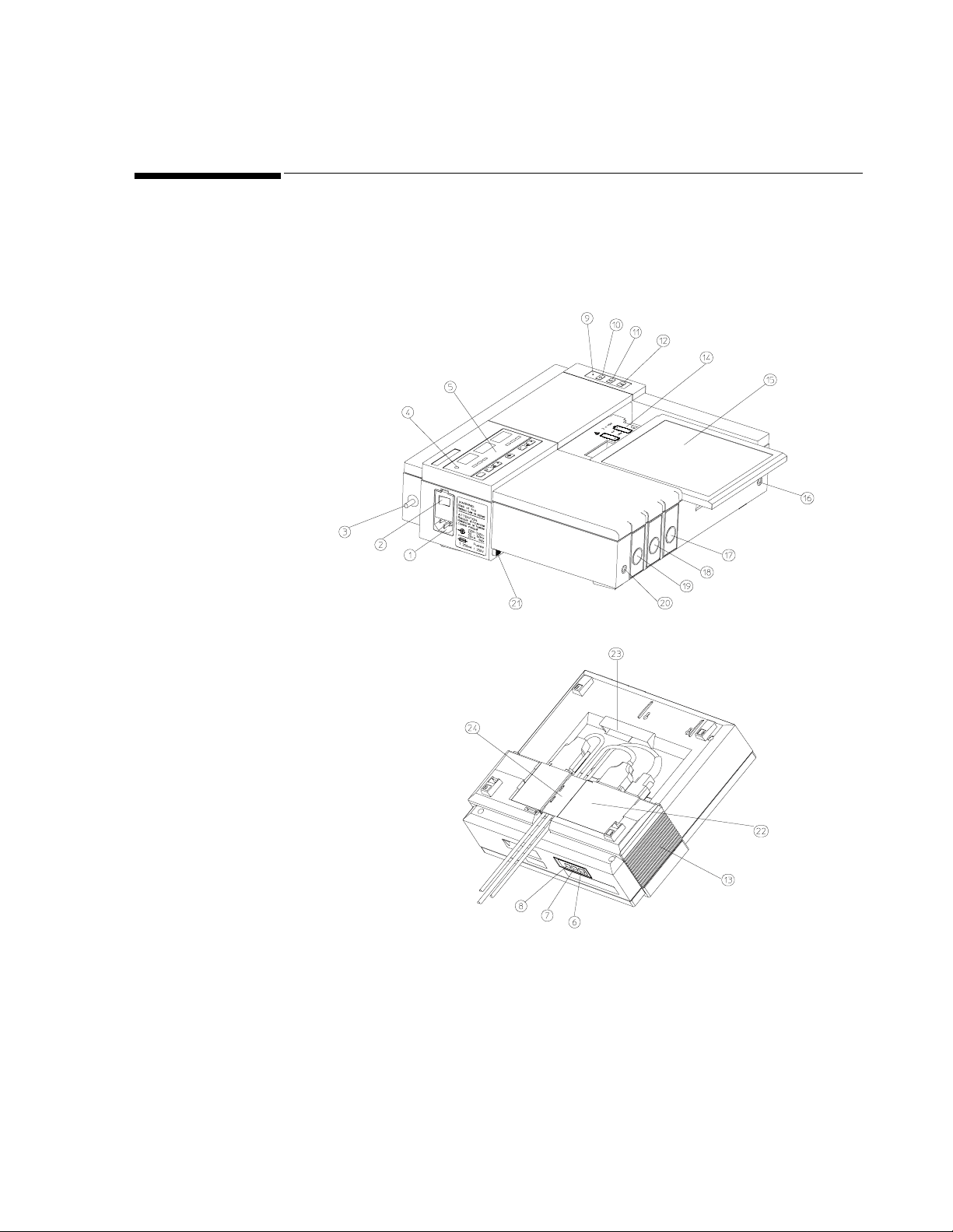
Figure 1-1 General Layout of the Series 50 A and Series 50 IP-2 Fetal
Monitors
Chapter 1 General Information 5
Page 16

Major Keys and Parts at a Glance
10. Recorder on/off key
11. Event marker key (Alert acknowledge key)
12. Paper advance key
13. Loudspeaker
14. Battery compartment
15. Paper table
16. Service socket
17. Series 50A: US2 Socket (not present on Single Ultrasound mode l)
18. Toco socket
19. Series 50A: Single Ultrasound M odel: US Socket
20. Socket for remote event marker
21. Lock-release button
22. Combi ne d interface module
23. Integrated carrying handle
24. Cable clamp
1. Mains socket
2. Monitor on/off switch
3. Equipotential grounding point
4. Monitor on/off light
5. Display panel
6. Time and date key
7. Paper speed key
8. Test key
9. Recorder on/off light
Series 50 IP-2: US2/ECG Socket
Double Ultrasound Model: US1 socket
Series 50 IP-2:US1 socket
6 Chapter 1 General Information
Page 17
Monitor Control and Display Panel
Monitor Control and Display Panel
M1351A Single Ultrasound Model
M1351A Dual Ultrasound Twins Model
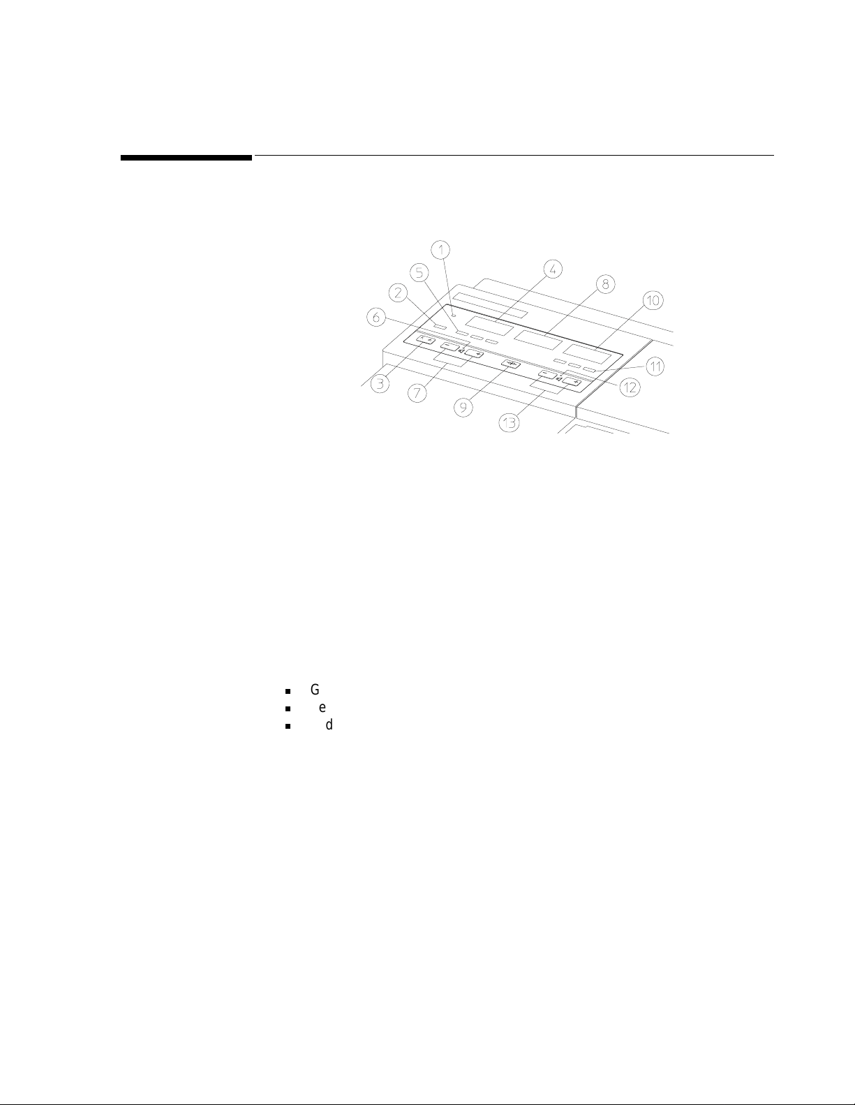
Figure 1-2 Layout of the Monitor Control and Display Panel
1. Monitor On/Off Light.
2. Telemetry Indicator. On when the Fetal Tele me try Rece iv er is con ne cte d a nd
switched on.
3. Function Key. Used to switch FMP and Fetal Alerting on and off.
4. US Display. Shows the FHR detected by the US transducer.
5. US Signal Quality Indicator. Indicates the quality of the signal detected by the US
transducer:
n
Green (optimum).
n
Yellow (fair to potentially poor).
n
Red (unacceptable).
6. US Speaker Light. On when you are hearing the US heartbeat.
7. US Volume Keys. Sets the volume and selects the US heartbeat.
8. Toco Display. Shows uterine activity.
9. Toco Baseline Key. Zeroes the Toco display and trace to 20 units.
1. Monitor On/Off Light.
2. Telemetry Indicator. On when the Fetal Tele me try Rece iv er is con ne cte d a nd
switched on.
3. Function Key. Used to switch Twins Offset, FMP, and Fetal Alerting on and off.
4. US1 Display. Shows the FHR detected by the US1 transducer.
Chapter 1 General Information 7
Page 18

Monitor Control and Display Panel
5. US1 Signal Quality In dicator. Indicates the quality of the signal detected by th e US1
transducer.
6. US1 Speaker Light. On when you are hearin g the US1 heartbeat.
7. US1 Volume Keys. Sets the volume and selects the US1 heartbeat.
8. Toco Display. Shows uterine activity.
9. Toco Baseline Key. Zeroes the Toco display and trace to 20 units.
10. US2 Display. Shows the FHR detected by the US2 transducer.
11. US2 Signal Quality Indicator. Indicates the quality of the signal detected by the US2
transducer.
12. US2 Speaker Light. On when you are hearing the US2 heartbeat.
13. US2 Volume Keys. Sets the volume and selects the US2 heartbeat.
M1353A Model 1. Monitor On/Off Light.
2. Telemetry Indicator. On when the Fetal Tele me try Rece iv er is con ne cte d a nd
switched on.
3. Function Key. Used to switch Twins Offset, Logic, FMP, and Fetal Alerting on and
off.
4. US Display. Shows the FHR detected by the US transducer.
5. US1 Signal Quality In dicator. Indicates the quality of t he signal detected by the US1
transducer:
6. US1 Speaker Light. On when you are hearin g the US1 heartbeat.
7. US1 Volume Keys. Sets the volume and selects the US1 heartbeat.
8. Toco Display. Shows uterine activity.
9. Toco Baseline Key. Zeroes the Toco display and trace to 20 units (when monitoring
externally) or 0 units (when monitoring internally).
10. US2/ECG Display. Shows the FHR detected by the ECG transducer.
11. US2/ECG Signal Quality Indicator. Indicates the quality of the signal detected by the
ECG transducer.
12. US2/ECG Speaker Light. On when you are hearing the ECG heartbeat.
13. US2/ECG Volume Keys. Sets the volume and selects the ECG heartbeat.
8 Chapter 1 General Information
Page 19

Accessories
Accessories
Series 50 A (M1351A)
The following accessories are supplied as standard with the Monitor:
l
One external Toco transducer (M1355-60011).
l
One ultrasound transducer (M1356-60011) (or two with the Dual Ultrasound
Model).
l
Two reusable transducer belts (M1562A) (or three with Dual Ultrasound Model).
l
Three transducer knob adapters (M1356-43201).
l
One power cord.
l
One pack of paper:
n
M1910A (USA/Canada)
n
M1911A (Europe)
n
M1913A (Japan)
l
One bottle of gel: 40483A (Acquasonic gel)
l
One User’s Guide.
l
One Installation and Servi ce Guide
l
One remote event marker (15249A).
Series 50 IP-2
The following accessories are supplied as standard with the Monitor:
(M1353A)
l
One external Toco transducer (M1355-60011).
l
One ultrasound transducer (M1356-60011).
l
One patient module M1364A with cables:
n
One DECG legplate adapter cable (M1362B)
n
One MECG adapter cable (M1363A)
l
Five spiral electrodes:
n
15133D Single spiral (USA).
n
15133E Double spiral (Europe).
l
Three reusable transducer belts.
l
Three transducer knob adapters (M1356-43201).
l
One power cord.
l
Equipotential grounding cable:
Chapter 1 General Information 9
Page 20

Accessories
n
8120-2961 (USA).
n
8120-4808 (Europe).
l
One pack of paper:
n
M1910A (USA/Canada)
n
M1911A (Europe)
n
M1913A (Japan)
l
One bottle of gel: 40483A (Acquasonic gel)
l
One Instructions for Use.
l
One Installation and Service Guide.
Documentation The following documentation is available for the Series 50 A and Series 50 IP-2 fetal
monitors. Unless otherwise specified localized versions are available.
l
Technical Data Sheets: Contain features and benefits, technical specifications,
accessories, ordering, upgrading and re-ordering information.
l
Service Documentation: All service documentation is in English.
l
Instructions for Use: Detailed operating information, care and cleaning, and safety
requirements.
l
Video Tapes: 30-minute VHS video tapes demonstratin g the Monitor.
l
Barcode Booklets: Labels and cards, and instructions on how to customize sheets of
nursing notes.
l
Digital Interface Protocol Specifications: Written as a programmer’s guide, describing
the data exchange between the Series 50 Fetal Monitors and an Information
Management System such as OB
TraceVue. English only.
10 Chapter 1 General Information
Page 21

Accessories
Options The following accessories can also be supplied when the appropriate option is ordered.
Accessories Option Model
Barcode Reader, including a reader and barcode booklet. This
H15 Series 50 A and Series 50 IP
requires Option J10 or J15.
Combined Interface Module for telemetry and obstetrical
J10
1
Series 50 A and Series 50 IP
surveillance systems (e.g. Philips OB TraceVue) and barcode
reader
Combined Interface Module for telemetry and obstetrical
J13
1
Series 50 A and Series 50 IP
surveillance systems (e.g. Philips OB TraceVue), includes an
interface cable M1350-61609.
• for Dinamap 1846 or
• COLIN Press-Mate/Nippon Colin Listmini Model BP-
8800 NIBP Monitor
Combined Interface Module for telemetry and obstetrical
J14
1
Series 50 A and Series 50 IP
surveillance systems (e.g. Philips OB TraceVue), includes an
interface cable M1353-61614
• for Nellcor Ox iFirst™ Fetal Oxygen Saturation Monitor
(N-400)
Modem Interface Module allows the transmission of fetal
J15
1
Series 50 A
trace data from a Series 50 A to a receiver (e.g., an OB
TraceVue system)
Fetal Movem ent Prof il e C02 Series 50 A a nd Series 50 IP
IUP Pressure Transducer (CPJ840J5) C07 Series 50 IP
Disposable IUP Catheter. This includes 1 x box M1333A
C08
2
Series 50 IP
(containing 10 catheters) disposable intraute rine sensor-tip
pressure catheters a nd M1334A reusable connector cable
1. Options J10, J13, J14 and J15 cannot be fitted at the same time
2. Not available in all countries.
Chapter 1 General Information 11
Page 22

Accessories
Accessories Option Model
Service an d In stallation Guide 0B3 Series 50 A and
Series 50 IP
Installation and Operating Guide Video
• VHS
• VHS
⁄ NTSC
⁄ PAL
0B5 Series 50 A and
Series 50 IP
Wall mounting kit 1AB Series 50 A and
Series 50 IP
Paper take-up tray
1
1AC Series 50 A and
Series 50 IP
Angled mounting kit 1AD Series 50 A and
Series 50 IP
Mobile cart 2AE Series 50 A and
Series 50 IP
1. Not compatible with the wall mounting kit.
12 Chapter 1 General Information
Page 23

Monitor
2
Technical Specifications
Power Requirements
The monitor is set for the corr ect voltage at the fact ory. Before you connect power, however,
ensure that the voltage label shows the correct setting for your country.
Operating Voltage: 100V - 120V∼ or 220V - 240V (±10%).
Line Frequency: 50 to 60Hz ±5%.
Power Consumption: 25VA max.
Battery Type: 2 x 1.5V (AA si ze ). Li f et im e > 1 y ear.
Environment The monitor should be used in an environment which is reasonably free from vibration,
dust, corrosive or explosive gases, extremes of temperature, humidity, etc. It operates within
specifications at ambient temperatures between 0 and 55°C. Ambient temperatures which
exceed these limits can affect the accuracy of the monitor and cause damage to the
components and circuits. Allo w at least 5cm (2i n) cle ara nce ar ou nd the monitor for proper
air circulation.
Operating Temp: 0 to +55°C (32°F to 131°F).
Storage Temp: -40 to +75°C (-40°F to 167°F), excludes transducers: -40 to
Relative Humidity: 5 to 95%.
+60°C (-40°F to +140°F)
Weight and
Height: 115mm (4.5in).
Dimensions
Width: 340mm (13.4in).
Depth: 308mm (12.1in).
Weight: 5.74kg (12.6lb) (without transducers).
Chapter 2 Technical Specifications 13
Page 24

Monitor
Displays
Numerical Display M1351A Single
Ultrasound Model: One heart rate display (orange) an d one uterine activity display
(green).
M1351A Dual
Ultrasound Twins Model:Two heart rate displays and one uterine activit y display.
M1353A Model: Two heart rate displays and one uterine activit y display.
Type: 7-segment LEDs (10mm).
FHR Range: 50 to 240 bpm.
Uterine Activity Range: -99 to +127 relative units.
Instrument Display Telemetry Mode is displayed if Option J10 is fitted and an or M13 10A or 80240A Fetal
Telemetry System is connected and switched on.
M1351A Single
Ultrasound Model: One signal quality indicator.
M1351A Dual
Ultrasound Twins Model:Two signal quality indicators.
M1353A Model: Two signal quality indicators.
Inputs M1351A Single
Ultrasound Model US socket accepts the M1356A ultrasound transducer. Toco
M1351A Dual
Ultrasound Twins Model US1 and US2 sockets accept M1356A ultrasound transducers.
M1353A Model US1 socket accepts the M1356A ultrasound transducer. To co
socket accepts the M1355A Toco transducer. Socket for the
Remote Event Mar k er (15 24 9A ), a nd another for servicing . T he
monitor automatically selects the correct operating mode.
Toco socket accepts the M1355A Toco transducer. Socket for the
Remote Event Mar k er (15 24 9A ), a nd another for servicing . T he
monitor automatically selects the correct operating mode.
socket accepts the M1355A external Toco or the M1350A/
8040A compatible internal Toco transducer. US2/ECG socket
accepts either the M1356A ultrasound tran sducer, or the
M1364A DECG/MECG patient module or the M1357A
DECG or the M1359A MECG transducer. There is a socket for
the remote event marker (15249A), and another for servicing.
The monitor automatically selects the correct operating mode.
14 Chapter 2 Technical Specificati ons
Page 25

Ultrasound Mode System: Pulsed Doppler oscillation.
Frequency: 998.4 kHz.
Repetition Rate: 3.2 kHz.
Ultrasound Intensity: 1.5mW/cm² average for each of the seven active surfaces.
Monitor
DECG and MECG
Mode
External Labor Signal Range: 0 to 127 units.
See Specifications for Transducers and Cables on page 17.
Offset Compensation: ±200 units.
Internal Labor Signal Range: -99 to +127 mmHg.
Patient Leakage Current:
≤10 µA
rms
.
Sensitivity: 40 µV/V/mmHg (M1348A).
5 µV/V/mmHg (M1334A and CPJ840J5).
Recorder Mechanism: 3-channel, high-resolution (8 dots/mm) thermal array recorder
with paper-end detection.
Paper Speeds: 1, 2 or 3 cm/min.
Recording Time Per Pack
of Paper: 1 cm/min (25 h).
2 cm/min (12 h 30 min).
3 cm/min (8 h 20 min).
Paper Advance Speed: 24 cm/min (with automatic stop at the paper-end mark).
Annotation: Time of day, date, and paper speed are printed automatically
every ten minutes. Monitoring mode is printed with every
alteration of parameter.
Paper: Fanfold paper with numbered pages.
FHR Scale: USA: 30 to 240 bpm @ 30 bpm/cm.
Other countries: 50 to 210 bpm @ 20 bpm /c m.
Labor Scale: 0 to 100 units @ 25 units/cm.
Chapter 2 Technical Specifications 15
Page 26

Monitor
Self-Test Facilities
Combined Interface Module
Modem Interface Module
Self-test fac il it ie s incl ud e:
System test: With no transducers connecte d (incl ude s a display and recorder
test).
Parameter test: With the appropriate transducer connected, the monitoring
mode (ultrasound or uterine activity) is tested.
Telemetry: M1310A Fetal Telemetry System.
System: M1383A/B/C OB TraceVue.
Either
Barcode Reader: SmartWand.
or
Maternal NIBP Monitor: Dinamap
COLIN Press-Mate
or
Nellcor OxiFirst
compatible.
Modem: Interface socket for an Philips-approved PCMCIA card modem.
Fetal T race Memory: Local fetal trace storage.
Barcode Reader: Smart Wand.
1846/8100.
/Nippon Colin Listm in i Model BP-8800.
Fetal Oxygen Saturation Monitor (N-400) or
Remote Event Marker (15249A)
RS232 Serial Interface: For internal use only.
Length: 2.8m/9ft 2in.
Weight: 75g/2.65oz.
16 Chapter 2 Technical Specificati ons
Page 27

Transducers and Cables
Transducers can be stored at temperat ure s between -40 and +60°C.
Transducers and Cables
Brown Toco Transducer (M1355A)
Blue1 Toco
Transducer
(M1355A)
Brown Ultrasound Transducer (M1356A)
Blue1 Ultrasound Transducer (M1356A)
System: Passive Straingauge.
Dynamic Range: 0 to 12N (overload protected).
Weight: 180g/6.3oz.
Cable Length: 2.5m/8ft 2in.
System: Passive Straingauge.
Dynamic Range: 0 to 12N (overload protected).
Weight: 180g/6.3oz.
Cable Length: 2.5m/8ft 2in or 0.7m/2ft 3in.
System: Pulsed Doppler.
Oscillator Frequency: 998.4kHz.
Weight: 185g/6.5oz.
Cable Length: + 2.5m/8ft 2in.
Size: 75mm/2.95in di ameter.
System: Pulsed Doppler.
Oscillator Frequency: 998.4kHz.
Weight: 185g/6.5oz.
Cable Length: 2.5m/8ft 2in or 0.7m/2ft 3in.
Size: 75mm/2.95in di ameter.
1. Indicates transducer is waterproof.
Chapter 2 Technical Specifications 17
Page 28

Transducers and Cables
DECG Transducer (M1357A)
MECG Transducer (M1359A)
Input Impedance: >10MΩ (differential, dc to 50/60Hz).
CMRR: >110dB (with patient cable, 51.5kΩ/0.047µF imbalance at line
frequency).
Noise: <4µV
(referred to input with 25kΩ).
p
Contact Potential
Tolerance: ±400mV.
Input Voltage Range: 20µV
Patient Leakage Current: <10µA
to 3mVp.
p
@ 120V/60Hz.
rms
Patient Auxiliary Current:<0.1µA (dc).
Dielectric Strength: 1500V
(spark-gap protected).
rms
Weight: 185g/6.5oz.
Cable Length: 2.5m/8ft 2in or 0.7m/2ft 3in.
Input Impedance: >10MΩ (differential, dc to 50/60Hz).
CMRR: >90dB (with patient cable, 51.5kΩ/0.047µF imbalance at lin e
frequency).
Noise: <4µV
(referred to input with 25kΩ).
p
Contact Potential
Tolerance: ±400mV.
DECG/MECG Patient Module (M1364A)
Input Voltage Range: 80µV
Patient Leakage Current: <10µA
to 4mVp.
p
@ 120V/60Hz.
rms
Patient Auxiliary Current:<0.1µA (dc).
Dielectric Strength: 1500V
(spark-gap protected).
rms
Weight: 175g/6.2oz.
Cable Length: 2.5m/8ft 2in.
The patient module has a 7-pin ECG connector into which you can plug either DECG
cable (M1362A or B) or MECG cable (M1363A).
Overall length: 2706mm (+30, -100mm)
Length of free cable: 2618mm (+30, -100mm)
Weight: 120 grams
Size: 88x42x30mm
Socket: DECG or MECG connection
18 Chapter 2 Technical Specificati ons
Page 29

Transducers and Cables
DECG Cable
(M1362A)
DECG Adaptor
Cable (M1362B)
MECG Cable
(M1363A)
M1364A With DECG
Cable M1362A
Cable weight: 22 grams
Cable Length: 666mm +/- 30mm
Cable weight: 35 grams (approx.)
Cable Length: 77cm (approx.)
Cable weight: 16 grams
Cable Length: 606mm +/-30mm
Patient Leakage Current: 120V at 60Hz, 10µA rms
Patient Auxiliary Current: < 0.1µA (dc)
Dielectric strength: 1500Vrms spark gap protected
Input Impedance: > 10MΩ
CMRR: with patient cable, 51.5kΩ/0.047µF imbalance at line frequency > 110dB
Noise: (referred to input with 25kΩ) < 4µVp
Contact Potential Difference: ±500mV
Input Voltage Range: 20µVp to 3mVp
M1364A With
MECG Cable
M1363A
IUP Quartz Transducer (1290C option J05)
Patient Leakage Current: 120V at 60Hz, 10µA rms
Patient Auxiliary Current: < 0.1µA (dc)
Dielectric strength: 1500Vrms spark gap protected
Input Impedance: > 10MΩ
CMRR: with patient cable, 51.5kΩ/0.047µF imbalance at line frequency > 80dB
Noise: (referred to input with 25kΩ) < 4µVp
Contact Potential Difference: ±500mV
Input Voltage Range: 80µVp to 4mVp
Dynamic Range: -50 to 300mmHg.
Sensitivity: 5µV/V/mmHg.
Non-linearity: Whichever is greater: ±1% of the reading or ±1mmHg.
Vo lum e Displacem en t: 0.2mm³/100mmHg.
Weight: 180g/6.3oz.
Cable Length: 3m/9ft 10in.
Length: 66mm/2.6in.
Chapter 2 Technical Specifications 19
Page 30

Transducers and Cables
Width: 37mm/1.5in.
Height: 21.7mm/0.9in.
Operating Temp: 15 to 40°C.
IUP Pressure Transducer (CPJ840J5)
Pressure range: -20 to + 300 mm Hg
Max. overpressure: 10,000 mm Hg
Sensitivity:
Resonance frequency: 300 Hz typical (transducer and dome)
Max. electrical excitation: 15 V DC or AC
Bridge resistance: 1000 Ohms (input and output)
Non-linearity and hysteresis: max. 0.5% of full scale
Zero balance: max. 0.15 mm Hg/°C
Operating temperature range: +10 to +50°C
Storage temperature range: -20 to +70°C
Isolation resistance: min. 1000 MOhms
Leakage current: max.1.5mA at 250V, 50 Hz
Weight: 24 grams (without cable)
Connector: Equipment specified
5µV/V/mmHg
20 Chapter 2 Technical Specificati ons
Page 31

Fitting the Monitor to a Su rface
The monitor can be mounted on (but not fixed to) an existing surface.
Fitting the Monitor to the Angle Mount
To fit the monitor to the angle mount:
1. Holding the monitor at a slight angle, put the front feet into the holes (A).
2. Lower the monitor till the back feet “click” into the holes (B). Make sure that all four
feet are located firmly in place.
3
Installing the Monitor
Figure 3-1 Fitting the Monitor to the Angle Mount
To remove the monitor from the angle mount hold the monitor in both hands, press both
lock-release butto ns (C) sim ul ta ne ous ly an d r em ove the monitor from the angle mo un t.
The lock mechanism may break if it is not fully released!
Chapter 3 Installing the Monitor 21
Page 32

Fitting the Monitor to a Wall
Fitting the Monitor to a Wall
Before you can fit the monitor to the wall, you must first secure the mounting plate to the
wall. For details of how to fit this plate to the wall, refer to the instructions supplied with it.
To fit the monitor to the plate:
1. Holding the monitor at a slight angle, put the front feet into the holes (A).
2. Push the monitor upright till the back feet “click” into the holes (B).
Wall Mount Dimensions
Figure 3-2 Fitting the Monitor to the Wall Mount
To remove th e monitor from the plate:
1. Hold the monitor in both hands
2. Press both lock-release buttons (C) simultaneously and lift the monitor away from the
plate.
Figure 3-3 Removing the Monitor from the Wall Mount
The wall mount is a metal plate that measures:
Width: 314mm (12.36 inches).
Height: 268 mm (10.55 inches).
Depth: 26 mm (1.03 inches).
22 Chapter 3 Installing the Mo nitor
Page 33

Fitting the Paper Take-Up Tray
To fit the paper take-up tray to the monitor:
1. Slide the tray between the guides (A) until the pins locate in the holes (B).
2. Pull the tray forward to lock it in place.
Fitting the Paper Take-Up Tray
Cart-mounted Paper Tray
Figure 3-4 Fitting the Paper Take-Up Tray to the Monitor
To fit the paper take-up tray (Option 1AB) to the mounting plate:
1. Holding the tray at a slight angle, put the top edge in the slot on the plate.
2. Swing the tray down into place.
Figure 3-5 Fitting the Paper Take-Up Tray to the Wall Mount
Attach the paper tray befor e installi ng the monito r on the a ngle mo unt. S lide the paper tray
into position so that the small hole in the attaching edge at the rear of the paper tray hooks
over the mounting projection in the angle mount itself. This secures the paper tray to the
angle mount.
Chapter 3 Installing the Monitor 23
Page 34

Carts
Carts
You can mount the Series 50 A and the S eri es 50 IP-2 fetal moni tors on the CL, CM o r CX
carts. Cleaning instructions for the carts and safety details are provided in the Carts
Equipment Note delivered with your cart.
Table 3-1 Carts: Specific ations
Specifications
Width (mm) 514 614 614
Depth (mm) 625 625 625
Height (mm) 805 989 1117
Weight ( kg) 24.2 50.6 63.4
Carts
CL (M1323A) CM (M1324A) CX (M1325A)
Table 3-2 Carts Replacement Parts
Replacement
Parts
Wheels M1324-42100 ✘✔✔
Drawers M1324-68500 ✘✔✔
CAM Mounting
Arm Kit
Mounting Kit IUP
Pole
Infusion Pole
Mount
Mounting Rail Kit 5061-8365 ✔✔✔
Part numbers
M1323-42075 ✔✘✘
M1323-68450 ✔✘✘
5061-8340 ✔✔✔
80310-68701 ✔✔✔
5061-8364 ✔✔✔
Fitting the Barcode Reader Holder
To fit the Barcode Reader holder (HBCS-2998) to the monitor or cart:
Cart CL
(M1323A)
Cart CM
(M1324A)
Cart CX
(M1325A)
1. Using ethanol, clean the surface of the monitor or cart thoroughly.
2. Peel off the backing from the adhesive strip and press the holder firmly into place.
Before using the holder, allow 24 hours for the adhesive to set.
24 Chapter 3 Installing the Mo nitor
Page 35

Introduction
4
Configuring the Monitor
This chapter describes how to confi gure the moni tor incl uding ti me and date format, paper
speed, and IUP scale. You can configure the monitor using any of the following methods:
l
Pushbuttons
l
Barcode Reader
l
PC
The tasks you can carry out are summarized in Table 4-1. To find out how to set the current
time, date, and paper speed, see Chapter5, “Setting Time, Date, and Paper Speed.”
Table 4-1Configuration Tasks
Barcode
Reader
✗✓
✗✗
✗✗
✗✓
✗
PC
✗
Task Buttons
Configure the time format ✓✓✓
Configure the date format ✓✓✓
Configure the IUP format ✓✓✓
Configure the paper format ✓✓✓
Configure the recorder print offset ✓✗✓
Configure the recorder heat adjust ✓✗✓
Configure the language op tion ✓✗✗
Marker for alert acknowledgement at Marker button ✓✗✗
Configure note tra nsmission on/off ✓✗✗
Configure interface setting ✓✗✗
Read the options installed ✗✗✓
Run the cyclic test
Run the permanent test
Read the error log ✗✗✓
Print the error log
Clear the error log
Write the serial number and set the options ✓✗✓
Enable fetal pulse oximetry interface ✓
1.
✗
2.
✓
2.
✓
2.
✓
Enable maternal blood pressure interface ✓✗✗
Enable NST timer, paper out alert ✓
1. However you can run the Permanent Test, which is similar. See page 70 for details.
2. See “Printing the Error Log” on page 38 for details
Chapter 4 Configuring the Monitor 25
✗
✗
Page 36

Configuring the Monitor Using Pushbuttons
Configuring the Monitor Using Pushbuttons
You can use the pushbuttons to set such settings as, time format, date format, IUP scale,
paper format, recorder scale offset, recorder heat, and language options.
To change a setting:
1. Disconnect all transducers from the monitor and disconnect or switch off Telemetry.
2. While pressing , press
The display shows C01 in the US1/US display and 0 or 1 in the Toco display.
3. Scroll through the menu by pressing the or key until you arrive at the
menu item you want to cha nge . Th e m en u i tem s a nd the ir setti ngs a re sho wn in T a bl e
4-2.
4. Press the key to change the setting (
5. Press
Test to store the new settings, or wait about 15 seconds without making any
keystrokes.
Test.
0 or 1).
26 Chapter 4 Configuring the Monit or
Page 37

Configuring the Monitor Using Pushbuttons
Table 4-2Configuration Options
Menu Setting Options Default
C01 Time Format 0=AM/PM
1=24-hour
C02 Date Format 0=Month/Day/Year
1=Day.Month.Year
C03 IUP Format 0=mmHg
1=kPa
C04 Paper Format 0=US (30-240)
1=Europe (50-210)
C05
Recorder P rint Of fset
1.
0 to 11
0=right 1=left
C06 Recorder Heat Adjust 0 to 11
0=minimum 11=maximum
C07 Language Option 1=International
2=French
10=Japanese
13=Chinese sim plified
C08 System Alert ac knowledge at Marker
button
0=off
1=on
C09 Note Output to System 0=off
1=on (Roman 8).
C10
Combined Interface Module Settings
2
0=Barcode Reader
1=Dinamap 1846/8100 NIBP Monitor
2=COLIN Model BP-8800 NIBP Monitor
3=Nellcor OxiFirst FSpO
C11 External Toco gain 0=100% External Toco gain
1=50%
Monitor (N-400)
2
0
0
0
0
0
11
1
0
1
0
0
C12 NST Timer,
Paper-Out-Alert
3.
C15 Remote Patient Data after phone
transmission
A01
A02
A03
1. To find the correct setting, connect a resting Toco transducer (one that is not under any load) to the monitor and th en change the
setting until the trace is recordin g 2 0 units on the pa per. Because of the 15-second time-out feature, and the delay between changing the setting and seeing the change on the paper, you may have to repeat this procedure to set the offset.
2. The interface to an NIBP monitor is only available on the Combined Interface Module with the label M1353-66531,E.
3. The NST auto recorder off option switches the recorder off automatically (advancing the paper to the next perforation) once the
NST time set has passed.
4. See -38 for more information on these menu items.
Print Error Log
Clear Error Log
Start Permanent Test
4.
4.
4.
See Table 4-3 4
0=Clear remote patient data
1=Keep remote patient data
0
Chapter 4 Configuring the Monitor 27
Page 38

Configuring the Monitor Using Pushbuttons
Table 4-3 NST Timer Paper-Out-Alert
Examples: How to Change the Time Format and IUP Format using Pushbuttons
Options NST Timer
0
1
2
3
4
5
Note— After you put paper into the recorde r, let it run for a few pages (use the
advance key) to allow the paper to align itself correctly to the right side.
Example 1:
To change the time format from AM/PM format to 24-hour format, do the following:
1. Disconnect all transducers from the monitor and disconnect or switch off Telemetry.
2. While pressing , press
3. Press the key to change the setting to
✗✗✗
✓✗✗
✓✗✗
✗✗✓
✓✗✓
✓✓✓
NST automatic
recorder off
Test.
Paper-Out-Alert
1.
4. Press
Example 2:
To change the IUP format from mmHg to kPa, do the following:
Disconnect all transducers from the monitor and disconnect or switch off Telemetry.
While pressing , press
Press repeatedly until
Press the key to change the setting to
Press
28 Chapter 4 Configuring the Monit or
Test to store the new settings.
Test.
C03 is displayed.
1.
Test to store the new settings.
Page 39

Configuring the Monitor Using Barcodes
The time format, date format, IUP scale and paper format can be set using barcodes. To
select a setting using a barcode, read the required barcode from the separate Feature Setting
Sheet provided with the Barcode Reader Kit.
To config ure the Modem Interface Module using a Barcode Reader, refer to “Using the
Modem Setup Barcodes” on page 164.
Configuring the Mo ni tor Using a PC
The service program (M1360-68875) allows you to carry out various extended
configuration and service functions on the monitor. Contact your Philips Sales Office for
details.
The Software Program is supplied in a kit which contains:
l
3.5 inch disk containing the software.
Configuring the Monitor Using Barcodes
l
Cable adapter for connecting to a PC.
The program can be run on an industry-standard PC. To use the program with a Vectra,
you must replace the adapter on the end of the cable with the one provided, and copy the
software onto a disk.
Figure 4-1 Cable for an Industry Standard compatible PC
Chapter 4 Configuring the Monitor 29
Page 40

Configuring the Monitor Using a PC
Installing the Service Program
Before you install the program, ensure that the serial port COM1 is set up as follows:
Transmission Rate 9600 BPS
Parity None
Word length (bits) 8
Stop-bits 1
This is done by giving the mode command (
mode com1:96,N,8,1) at the DOS
prompt. Refer to your MS-DOS Manual for details.
To install the program:
1. Switch on the PC.
2. Create a directory for the program files. For example, to create a directory called
service, at the DOS prompt type in:
md service
and press Enter.
3. Insert the program disk into drive A.
4. At the DOS prompt type
A: and press Enter.
5. At the A: prompt, type:
copy pegserv.exe c:\service
and press Enter. Where service is the directory you created to contain the
program files.
The program is copied to
c:\service
Make sure that the serial interface configuration on the PC is set up as follows:
Datacom-Configuration
Parameter Serial
Transmission Rate (BPS)9600
Word Length (bits) 8
Stop-Bits 1
Parity None
%ON /%OFF Pacing Off
CTS Line Regard
DSR Line Regard
DCD Line Ignore
Power to Interface Off
30 Chapter 4 Configuring the Monit or
Page 41

Connecting the PC to the Monitor
Configuring the Monitor Using a PC
Figure 4-2 Service Socket
Connect the cable from the COM1 port of the PC to the service socket (1).
Loading the Service Program
Using the Service Program
1. Switch on both the monitor and the PC.
2. Load the program by doing one of the following:
n
If the program files are contained in a directory, change to that directory and
enter:
pegserv
n
If you want to load the program from drive A: (or another drive)
i. Insert the program disk into drive A:
ii. Chang e to driv e A: and enter:
pegserv
n
If you are using Windows 98/ NT: Start the service program by double-clicking
on the pegserv icon o r on the filename pegserv-exe
3. The program is now loaded and ready for use.
When the program has been loaded onto your PC, the main menu is displayed. (If the
menu is not displayed, an error message is displayed along the bottom of the screen.)
Chapter 4 Configuring the Monitor 31
Page 42

Configuring the Monitor Using a PC
Main Menu
To select an item from the menu, move the cursor to the item you require and press Enter.
Series 50 Fetal Monitor Configuration and Service Software Rev A.nn.nn
Main Menu
Configuration Settings
Recorder Adjustmen ts
Service Menu
Exit
MESSAGE:
Select with >cursor keys< or >E, S, D, X< then press <ENTER> to execute!!
Configuring the
Monitor
Use the , , , keys on the keypad, or the
E, S, D or X keys to move the cursor.
While the service program is working , messages maybe displayed along the bottom of the
screen. For example:
Reading Recorder Adjustments from the Monitor.
Reading Serial Number from the Monitor.
Clearing the Error Log.
Series 50 Fetal Monitor Configuration and Service Software Rev A.nn.nn
Configuration Setting:
Function : Actual Setting is Select
Paper Scale : US US EU
Time Format : AM/PM AM/PM 24h
Date Format : US US EU
IUP Scale : mmHg mmHG kPA
MESSAGE:
Select with >cursor keys< or >E, S, D, X< then press <ENTER> to execute!!
To change a setting:
32 Chapter 4 Configuring the Monit or
Page 43

Configuring the Monitor Using a PC
1. Using the appropriate keys, move the cursor to the selection you require.
2. Press Enter.
To return to the Main Menu:
1. Move the cursor to
Return to Main Menu.
2. Press Enter.
Example
On the screen above, the actual setting of the paper scale is US. To change this to EU, move
the cursor to
EU in the Selection: column and press Enter. The program will
reconfigure the monitor for the European paper scale.
Note— The actual settings on your monitor may be different from those shown.
Chapter 4 Configuring the Monitor 33
Page 44

Configuring the Monitor Using a PC
Adjusting the
Recorder
The Recorder Heat-Adjust is to compensate for different tolerances in the paper.
Series 50 Fetal Monitor Configuration and Service Software Rev A.nn.nn
Recorder Adjustments:
Recorder Heat Adjust: Actual Value is: |
Recorder Zero Adjust: Actual Value is: |
Return to Main Menu
MESSAGE:
Select with >cursor keys< or >E, S, D, X< then press <ENTER> to execute!!
Selected Value is |
∨
|……………|
Min Max
Selected Value is |
∨
|……………|
Left Right
To change a setting:
1. Using the appropriate keys, move the cursor to the selection you require.
2. Press
Enter.
To return to the Main Menu:
1. Move the cursor to
2. Press
Enter.
Return to Main Menu.
Example
On the screen above, the actual value of the Recorder Zero-Adjust is closer to the
left side. If this is not printed exactly on
20 on the Toco channel, then you must realign the
Selected Value is: to the right or to the left and then press Enter. The program
will adjust the recorder accordingly.
Note— The actual values on your monitor may be different from those shown.
34 Chapter 4 Configuring the Monit or
Page 45

Service Menu
Configuring the Monitor Using a PC
Series 50 Fetal Monitor Configuration and Service Software Rev A.nn.nn
Service Menu
Serial Number : 2948G00010
Software Revision : A.02.03
Cyclic Test
Read options
Read ErrorLog
Clear ErrorLog
Write Ser.nr./Set Options
Fetal Heart Rate Alerting
Return to Main Menu
MESSAGE:
Select with >cursor keys< or >E, S, D, X< then press <ENTER> to execute!!
To select an item from the menu, move the cursor to the item you require and press
However, before you select
Cyclic Test, connect ultrasound, Toco and DECG
Enter.
transducers to the monitor.
Note— The serial number and software revision of you r monitor may be different
from those shown.
Running the Cyclic Test
This runs a continuous Self Test. Any errors are written to the Error Log and can be read
Read ErrorLog. Press an y key to sto p the te st and r eturn to the S ervice M enu.
using
Series 50 Fetal Monitor Configuration and Service Software Rev A.nn.nn
CYCLIC TEST is started
It starts a continuous self test of the monitor
Press any key to stop this test
Read ErrorLog to see the errors that occurred while self testing
MESSAGE:
Note— During the test, the keys on the front panel are disabled.
Chapter 4 Configuring the Monitor 35
Page 46

Configuring the Monitor Using a PC
Reading the Options
This lists the options installed on the monitor. Press any key to return to the Service Menu.
Series 50 Fetal Monitor Configuration and Service Software Rev A.nn.nn
- Fetal Movement Profile
- External Twin Monitoring
MESSAGE:
Press any KEY to continue!
Implemented Options :
Note— The options on your monitor may be different from those shown.
36 Chapter 4 Configuring the Monit or
Page 47

Configuring the Monitor Using a PC
Reading the Error Log
This displays the error log. (See -44 for the list of error log messages.)
> PAGE 1 < Errorlog of : 2948G00010
Err. Count 1st Date+Time last Date+Time
Code nnnn yy/mm/dd HH:MM yy/mm/dd HH:MM
|-| |--| |------.----| |------.----|
Use >W< to Write ErrorLog Data to File >ErrLog.DAT<
use CursorKey >Down< or >X< to see next Page, <ENTER> to leave
Up to 16 err or message s can be di splaye d on a scr een. To see the next o r prev ious scr een , use
the or keys on the keypad, or the
more Data available
SHIFT and PrtSc to print a page on LPT1.
Press
Enter to return to the Service Menu.
Press
is displayed.
To write the error log data to a file, press the
E or X keys. At the end of the Error Log, No
W key. The data is then stored as
ERRLOG.DAT in the directory containing PEGSERV.EXE. The data is stored as ASCII
characters, and therefore the file can be printed using the DOS Command
ERRLOG.DAT
. The file is overwritten each time you press the W key.
print
Chapter 4 Configuring the Monitor 37
Page 48

Configuring the Monitor Using a PC
Printing the Error Log
To print the error log, complete the following steps:
1. Disconnect all transducers from the monitor and disconnect or switch off Telemetry.
2. Switch on the recorder.
3. Press and
n
C01 is shown in the US1/US display.
n
0 or 1 is shown in the Toco display.
Test at the same time:
4. Press again to select the Service Function Menu:
n
A01 (Print the Error Log) is shown in the US1/US display.
5. Press to print the error log. The display shows:
nnn nnn nnn
The following table lists the error log and permanent test functions, and their
corresponding menu numbers.
Table 4-4 Service Function Menu Numbers and Error Log Functions
Menu No. Function
A01 Print the Error Log
A02 Clear the Error Log
A03 Start the Permanent Test
503 0001 91/05/12 17:33 91/05/12 17:33
510 0010 91/05/12 17:36 91/05/17 10:45
504 0001 91/05/12 17:33 91/05/12 17:33
506 0010 91/05/12 17:36 91/05/17 10:45
FIC
C1C4 0001 91/05/12 17:33 91/05/12 17:33
C146 000A 91/05/12 17:36 91/05/17 10:45
02/18/91 A.01.00 M1351A 3028G00203
Figure 4-3 Example of an Error Log
38 Chapter 4 Configuring the Monit or
Page 49

Configuring the Monitor Using a PC
The error log lists the following (above the line and left to right):
n
Error code.
n
Number of times the error has occurred (the error counter uses hexadecimal
notation).
n
Date and time the error first occurred.
n
Date and time the error last occurred.
n
Factory Information Code (FIC).
The error log lists the following (below the line and left to right):
n
Present date.
n
Software revision number.
n
Type of monitor.
n
Serial number of monitor.
Note— If the characters
action. The information contained in the
information for internal use only. If you have a technical problem, contact
the Philips support organization.
FIC are printed without other information, do not take any
FIC section is additional
Chapter 4 Configuring the Monitor 39
Page 50

Configuring the Monitor Using a PC
Clearing the Error Log
To clear the error log, complete the following steps:
1. Disconnect all transducers from the monitor and disconnect or switch off Telemetry.
2. Press and
n
C01 is shown in the US1/US display.
n
0 or 1 is shown in the Toco display.
Test at the same time:
3. Press again to select the Function Menu:
n
A01 (Print the Error Log) is shown in the US1/US display.
4. Press to select
A02 (Clear the Error Log).
5. Press to clear the error log.
The confirma tion me ssage
Series 50 Fetal Monitor Configuration and Service Software Rev A.nn.nn
Serial Number : 2948G00010
Software Revision : A.02.03
Are You Sure? asks if you do wan t to clear t he err or log:
Service Menu
Cyclic Test
Read options
Read ErrorLog
Clear ErrorLog Are you sure?
Write Ser.nr./Set Options
Fetal Heart Rate Alerting
MESSAGE:
Select with >cursor keys< or >E, S, D, X< then press <ENTER> to execute!!
l
Press the Y key to clear the error log
Return to Main Menu
or
l
Press the N key.
You then return to the Service Menu.
40 Chapter 4 Configuring the Monit or
Page 51

Configuring the Monitor Using a PC
Writing/Resetting the Serial Number and Setting the Options
Note— You can write the serial number to the monitor only if you have replaced the
CPU Board with an exchange board. If you have accidentally entered the
wrong serial number, you can reset it using an access code available from
your Philips Medical Response Center or from the Philips T e chnical
Marketing information "Softserver" page on the Philips Intranet.
The serial number can only be written once to the exchanged bo ard with
each access code.
Series 50 Fetal Monitor Configuration and Service Software Rev A.nn.nn
Service Menu
Type in 10 alphanumerics from Serial Number - Label and press >ENTER<
MESSAGE:
To write the serial number:
1. Using the keyboard, type in the serial number of the monitor. (This is printed on the
side of the monito r.)
2. Press
Enter.
A confirmation message asks if the serial number is correct:
n
If it is correct, press the Y key.
n
If it is not correct, press the N key and retype the serial number.
You then go to the
Set Options screen .
Chapter 4 Configuring the Monitor 41
Page 52

Configuring the Monitor Using a PC
To select an option:
1. Using the appropriate keys, move the cursor to the selection you require.
Series 50 Fetal Monitor Configuration and Service Software Rev A.nn.nn
Select Options according to the labels on the monitor
Option: Actual Setting is: Selection:
#C.01 TWIN: OFF OFF ON
#C.02 FMP: OFF OFF ON
Write Options
MESSAGE:
Select with >cursor keys< or >E, S, D, X< then press <ENTER> to execute!!
2. Press
Enter.
To write the options to the monitor and return to the Main Menu:
1. Move the cursor to
Write Options.
2. Press Enter.
A confirmation mess age asks if the selected options are correct.
The following shows the resetting screen that is displayed when you need to reset the serial
number:
Series 50 Fetal Monitor Configuration and Service Software Rev A.nn.nn
NOTE: resetting the Serial Number is protected by Access Code
Serial Number : 3151G00026
Type in 4 digit code from factory TME and press <ENTER>
MESSAGE:
>----<
Contact your Philips Medical Response Center for your access code. Make sure you have
the serial number of the original CPU board available.
42 Chapter 4 Configuring the Monit or
Page 53

Configuring the Monitor Using a PC
FHR Alerting Enable/Disable
This screen enables you to enable or disable the fetal heart rate alerting.
In order to change this configuration, you must enter the access code. You can obtain this
code from your Philips Medical Response Center or from the Philips Technical Marketing
page "Softserver" on the Philips Intranet. (There is a specific access code to enable the
alerting, and a specific access code to disa ble the alerting .)
To enable or disable the alerting, enter the specific code to enable or disable the alerting.
Series 50 Fetal Monitor Configuration and Service Software Rev A.nn.nn
NOTE: Changing the Alert Option is protected by Access Code !
Alert Option is ENABLED. Do you want to DISABLE the Alert option?
Press <Y> for YES or <N> for NO!
MESSAGE:
Chapter 4 Configuring the Monitor 43
Page 54

Error Log Messages
Error Log Messages
Table 4-5Error Log Messages
Message Location of Error and Solution
Err 18 Incorrect typ e of paper loa d ed (same as Err PAP).
Err 19 Battery low or empty of charge (same as Err bAt).
Err 70 Modem not responding.
Err 77 Error during transmission of data.
Err 500 General failure - no spec ific location.
Replace with recomm ended paper.
Change the batteries as soon as possible.
Modem is either not installed, incorrectly installed, faulty or not an approved
model.
Probably due to external sources. Retransmit the data.
See the Troubleshooting Flowchart in Chapter 8.
Err 501,
513
Err 502 Power Supply Board.
Err 503 CPU Board.
Err 510 Recorder Board.
Err 511 Front End Board (Dual Ultrasound model).
Err 512 Intrapartum Board.
Err 531 Combined Interface Board.
Err 532 Modem Interface Board.
Err 601 Paper feed.
Err 602 Incorrect type of paper.
Front End Board (Single Ultrasound model).
See the Troubleshooting Flowchart in Chapter 8.
See the Troubleshooting Flowchart in Chapter 8.
See the Troubleshooting Flowchart in Chapter 8.
See the Troubleshooting Flowchart in Chapter 8.
See the Troubleshooting Flowchart in Chapter 8.
See the Troubleshooting Flowchart in Chapter 8.
See the Troubleshooting Flowchart in Chapter 8.
See the Troubleshooting Flowchart in Chapter 8.
See the Troubleshooting Flowchart in Chapter 8.
Load paper with the correct scale or change the setting.
Err 610 No loudspeaker, or fuse has blown.
See the Troubleshooting Flowchart in Chapter 8.
44 Chapter 4 Configuring the Monit or
Page 55

Table 4-5Error Log Messages
Message Location of Error and Solution
Err 611 Wrong loudspeaker impedance.
See the Troubleshooting Flowchart in Chapter 8.
Err 800 Software error: checksum wrong or download incomplete.
Reload the software.
Err 820 Upgrade Key is for a different type of monitor.
Use the correct key.
Err 888 No software upgrade done.
Disconnect transducers and tele met ry first.
Error Log Messages
Chapter 4 Configuring the Monitor 45
Page 56

Error Log Messages
46 Chapter 4 Configuring the Monit or
Page 57

Time and Date
5
Setting Time, Date, and Paper Speed
To set the time and date:
Figure 5-1 Time and Date Paper Speed Controls
1. Press to display the current time. The hour is shown in the US1/US display and
the minutes in the Toco display. The US1/US display flashes to show that the hour
can be changed.
2. Press or to set the hour. Press and hold the key to change the setting
more quickly.
3. Press again and the Toco display flashes t o show that the minutes can be
changed.
4. Press or to set the minutes.
5. Repeat steps 3 and 4 to set the month, day and year, and to return to the normal
display.
In North America, the month is shown in the US1/US display and the day in the Toco
display. In other countries, the day is shown in the US1/US display and the month in the
Toco display.
You also return to the normal display automatically if you wait eight seconds without
pressing a key. When you return to the normal display, the new time and date are set, and
the time, date and paper speed are printed on the paper.
Chapter 5 Setting Time, Date, and Paper Speed 47
Page 58

Paper Speed
Paper Speed
To set the paper speed:
Figure 5-2 Paper Speed Controls
1. Press to display the current speed.
2. Press or to set the speed.
3. Press to return to the normal display.
You also return to the normal display automatically if you do not press any key for a
few seconds. When you return to the normal display, the new paper speed is set, and
the time, date, speed a nd m onitoring modes are printed on the pa per.
The paper speed can be 1, 2 or 3 cm/min. The default for North America is 3 cm/min; the
default for other countries is 2 cm/min.
Note— The ACOG technical bulletin on FHR monitoring states that “accurate
pattern recognition is difficult if not impossible at 1 cm/min and that 1 cm/
min is only recommended for more economic screening. When FHR
abnormalities arise, the faster paper speeds will enhance FHR pattern
recognition”. In addition, since a change in paper speed will result in a
change in the appearance of an FHR trace, care must be taken to ensure ALL
monitors in your institution are consistently set at the same speed or speeds.
48 Chapter 5 Setting Time, Date, and Paper Speed
Page 59

System Overview
The boards and their interconnections are shown in the following figure.
System Overview
6
Theory of Operation
The CPU board, which has overall control of the entire system, contains flash EPROMs
containing all the s ystem sof tware. Th e softwa re for the Co mbined I nterface Bo ard (if one is
fitted) is loaded from this ROM area.The signals from the transducers receive some analog
conditioning on the Front End Board and are then digitized on th e CPU Board. The CPU
Board includes a digital signal processor. The results of the processing are distributed to the
outputs (for example, the Recorder, “traffic lights” and Combined Interface Board).
Chapter 6 Theory of Operation 49
Page 60

Booting and Self Tests
Booting and Self Tests
The monitor carries out a basic test every time it is switched on, and then at periodic
intervals whil e it is on. There are two typ es of t es t:
l
Programs that check the hardware on each board.
l
Programs that carry out check sums on the individual portions of code that are loaded
from the Flash EEPROMs.
When the moni tor is switched on , the initial reset generated by the power supply is fed to
the CPU Board, where it is latched and passed to the other boards. Each board latches the
reset to light its error LED. The LED can only be switched off by the CPU Board delatching it.
All error LEDs are on at the start of the tests. If a hardware error is detected on a board, its
error LED stays on and its error code is shown on the display. (The error code is the last
three digits of the bo a r d ’s part number.) But note that if any element in the display chain is
not working, the errors may not be displayed. If a board passes its test, the LED goes out,
and the next board in the sequence is tested.
The Power Supply Board, Front End Board and Recorder Board have no processor and so
are tested by the CPU Bo a rd.
The boards are tested in the following sequence:
1. CPU Board.
2. Power Supply Board.
3. Front End Board.
4. Recorder Board.
5. Combined Interface Board (if one is fitted).
6. Modem Interface Board (if one is fitted).
The processor on the CPU Board runs a self-test program from the Flash EEPROMs to test
certain function s of the CPU Board:
l
If the test fails, the red LED stays on and “Err 503'' is displayed .
l
If the test is successful, the red LED on the board goes out.
The current limits of the outputs of the Power Supply Board are then checked:
l
If any currents are out of limits, ``Err 502'' is displayed. Note that this does not
necessarily mean that the Power Supply Board is faulty (for example, a short on
another board could be drawing too much current).
l
If the test is successful, the red LED on the CPU Board is switched off.
l
All other boards are then tested. The red LEDs on the Front End Board and the
Recorder Board are lit for about 1 s, and then switch ed off when the test is successful.
50 Chapte r 6 Theory of Operation
Page 61

Booting and Self Tests
The Combined Interface Board and the Modem Interface Board both have processors that
test the interface board once the DMA control logic has been checked.
The CPU Board boots a test program from the ROM to the on-board Digital Signal
Processor (DSP) program RAM. The DSP then runs it. The program tests the DSP and its
associated components, and writes the results to the DSP RAM. The CPU reads the RAM
to find out the exit status of the tests. If the te st fail s, the LE D stays on and the err or code is
displayed.
The signal processing software is stored as two programs in Flash EEPROMs. This carries
out US/US or US/ECG functions. The CPU Board transfers the US/US or US/ECG
program from its Flash EEPROMs to the program RAM of the DSP.
All the time the monitor is on, the CPU Board checksums the signal processing software
and the Flash EEPROMs at 1-minute intervals. If the tests fail, the system is reset and
rebooted. And every 300ms, a watchdog ASIC is fed patterns by the CPU Board 68000. If
the ASIC does not receive a pattern, it resets the system.
Chapter 6 Theory of Operation 51
Page 62

Front End Board
Front End Board
M1351A
(M1353-66501
and
M1353-66511)
The Frontend board (M1353-66501 − single, M1353-66511 - dual) contains the analog
circuitry for measuring all the possible parameters of the M1351A. One IC on the board
provides the US timing and window control. Each type of transducer has a specific mode
resistor which is recognized by the M1351A when the transducer is connected to an input
socket. In this way, the user can be warned if a wrong transducer is connected. The marker
cable is also connected to the Front End Board.
The frontend boards used with software at Rev E and higher are triangular in shape, not
rectangular.
M1353A (M1353-66512)
Ultrasound
The ultrasound transducer transmits 998.4kHz ultrasound bursts which are generated by
the digital control ICs. The burst widths are controlled by software. The transmitter
amplifier supplies 5V
998kHz signal is amplified by a high frequency amplifier with a gain of 120 and then split
to provide a referen c e path
independently controlled by software in their receive windows by the control ICs. The
demodulated LF signals are bandpass filtered (100 to 450Hz) and amplified by a software
controlled gain of 180 to 1860 in eight steps. The FMP-LF path is independently
demodulated, bandpass filtered and amplified by a facto r of 18.
Toco
The excitation voltage is a biphase 2.4kHz rectangular continuous wave with an amplitude
of 5V
the sense input is amplified by 786 (5
and lowpass filtered with a cut-off frequency of 7.5Hz.
Used in monitors with serial number prefix ≤ 3652G.
The Frontend board contains the analog circuitry for measuring all the possible parameters
of the M1353A. An IC on the board provides the US timing and window control, and
. The frequency is generated in the control chip by dividing the 4MHz system clock.
pp
_ at the Cardio sockets. The repetition rate is 3.2kHz. The received
pp
a and a compare path b. The tw o demodulators a and b are
µ;V/V/mmHg), rectified with a synchronous detector
52 Chapte r 6 Theory of Operation
Page 63

Front End Board
controls the ECG. Each type of transducer has a specific mode resistor which is recognized
by the M1353A when the transducer is connected to an input socket. In this way, different
types of transduc er can be used without the user having to recalibrat e the system. The
marker cable is also connected to the Frontend Board.
apegblk5
Chapter 6 Theory of Operation 53
Page 64

Front End Board
Frontend Board for M1353A (M1350-66517)
Used in monitors with serial number prefix ≤ 3720G.
Figure 6-1 Frontend Board
The Frontend board contains the analog circuitry for measuring all the possible fetal
parameters of the M1353A. The FOCUS ASIC on the board provide the US timing and
window control, and controls the ECG.
Each type of transducer has a specific mode resistor which is recognized by the M1353A
when the transducer is connected to an input socket. In this way, different types of
transducer can be used without having to recalibrate the system.
ECG The FOCUS IC divides the 4 MHz system clock to generate a 181 kHz clock. A power
stage generates the power clock for the ECG transducers. The ECG signal modulates the
supply current of the transducer. The modulated current is detected, amplified and
bandpass filtered (1 - 250 Hz). Block DECG/MECG1 is unused.
US The US transducer transmits 998.4 kHz ultrasound bursts which are generated by the
FOCUS IC. The burst widths are controlled by softw are. The t ransmitter amplifier suppl ies
at the Cardio sockets. The repetition rate is 3.2 k H z.
5 V
pp
The received 998 kHz signal is amplified by a high frequency amplifier with a gain of 120
and then split to pr ovide a re ference path
b are independently controlled by software in their receive windows by the FOCUS IC.
and
a and a compare path b. The two demodulators a
The demodulated LF si gnals are bandpass filtered (1 00 - 500 Hz) and amplified by a
software control led gain of 180 to 1860 in eight steps. The
FMP-LF path is independently
demodulated, bandpass filtered and amplified by a facto r of 18.
TOCO The pins of the TOCO/IUP socket are electrically isolated, connected by three transformers
(excitation, sense and mode). The excitation voltage is a 2.4 kHz square wave with an
amplitude of 3.5V
. The frequency is generated in the control chip by dividing the 4
RMS
MHz system clock.
The sense input signal is amplified by 93.75 (40
µ;V/V/mmHg) or 750 (5µ;V/V/mmHg),
rectified with a synchronous detector and lowpass filtered with a cutoff frequency of 7.5 Hz.
All LF signals are multiplexed, sampled at either 1600 or 800 Hz, and A/D converted with
12-bit resolution.
The marker cable and the switch board are also connected to the Frontend board.
54 Chapte r 6 Theory of Operation
Page 65

Power Supply Board (M1353-66502)
Power Supply Board (M1353-66502)
The Power S upply Board operates as a linear regulated power supply with rectifier, capacitor
and regulator. It generates the following voltages:
Regulated dc:
Unregulated dc: +7V to +12V
±12V, +5V and +24V
±12V and +5V have an electronic short circuit curr e nt li mi t. The +2 4V dc regulator works
independently from the others. The +24V are used for the thermal printhead fed through
the recorder IF-board. The internal +2. 5V reference voltage is generated from the +24V, so
if the 24V section is inoperative, the rest of the power supply won’t work. The -12V
regulator a lso needs the regulated +5V to work correctly. The reset (open collector output)
is active low, when either the +5 V i s lower than +4.6V o r the + 24 V i s lower than +14.8V. If
the +5V is highe r than 6.2V (this can be caused by any failure of the power supply or the
other boards) the over-voltage protecti on is triggered and pulls down the voltag e to about
3.4V. This state can on ly b e re liev ed by sw itchi ng t he mo nitor o ff and on (i f the failu r e isn ’t
still remaining).
Chapter 6 Theory of Operation 55
Page 66

CPU Board (M1353-66503 and M1353-66513)
CPU Board (M1353-66503 and M1353-66513)
CPU Board M1353-66503
CPU Board M1353-66513
This board works with the 4 ohm loudspeaker and is used in:
l
M1351A monitors with serial number prefix ≤ 3604G.
l
M1353A monitors with serial number prefix ≤ 3605G.
This board works with the 8 ohm loudspeaker and is used in:
l
M1351A monitors with serial number prefix ≥ 3651G.
l
M1353A monitors with serial number prefix ≥ 3652G.
apegblk2
The Central Processor Unit (CPU ) Board is the heart of the system and controls most other
boards. The 68000 microprocessor and associated support ICs provide system functions;
the bus control section controls the system bus. The board contains two Flash EEPROMs
which contain all the system software.The board includes the following sections:
l
Microprocessor Section:
n
68000 microprocesso r.
n
Flash EEPROMs containing all system software and a boot program allowing
n
software upgrades via the Service Connector.
56 Chapte r 6 Theory of Operation
Page 67

n
CMOS RAM memory, backed by a battery to store short time device settings etc.
n
A non-volatile EEPROM memory for permanent device and user settings.
n
A real-time clock, battery-backed and power-fail protected. The processor has
access to all clock registers.
n
The multiplexer ASIC contains a watchdog function which monitors the
operation of the microprocessor and restarts the system if it is not served at a
constant rate.
l
AD/DA Section:
n
After system startup, the CPU starts the A/D control chip, which divides the
signal fr o m the clock circuit and generates an i nterrupt every 2.5 ms.
n
The 68000 on the CPU Board then programs the multiplexer to select the analog
channels for A/D conversion: the analog/digital conversion of up to eight
channels is done by the multiplexer without further intervention by the CPU. A/
D conversion is by successive approximation. After the next interrupt, the CPU
reads the results stored in registers within the multiplexer. The multiplexer also
receives values from the CPU for audio output.
CPU Board (M1353-66503 and M1353-66513)
n
All LF signals are multiplexed, sampled at either 1600 or 80 0Hz, and A/D
converted wi th 12-bit resolution.
l
Digital Signal Processing Section:
n
Signal processo r and RAM.
n
DMA logic.
DSP software rebooted when the US2 channel socket is connected/disconnected.
l
Bus Control Section:
n
Address and data bus control chips.
n
Board select logic to access all system boards.
n
DMA circuits to allow DMA access via the system bus to the Combined Interface.
n
A crystal quartz oscillator and related circuitry provide several local and bus clock
frequencies.
l
Service Interface: An RS232 serial interface is provided for use during production and
service. Connection is via a stereo phone jack on the front panel.
n
Serial interface for option and software upgrades.
n
Settings and configuration via an external computer.
Chapter 6 Theory of Operation 57
Page 68

Display Board (M1350-66520)
Display Board (M1350-66520)
The display board consist of the following main parts:
l
Keys
pegdbd40
l
Display Controller
l
Backlights
l
LEDs
Signals at the keys are fed to the recorder board via the ribbon cable and are sampled by the
controller. Display data is loaded from the recorder board to the display controller ASIC via
a serial data link. The controller multiplexes this data to the LEDs and backlights. The
multiplexer clock is served by th e recorder board. The clock speed is 3.2kHz to avoid
interference between the US channel and the display multiplexer.
58 Chapte r 6 Theory of Operation
Page 69

Recorder Interface Board (M1353-66510)
Recorder Interface Board (M1353-66510)
apegblk3
The Recorder Board provides the interfaces to the recorder and the display. The recorder
interface consists of:
l
The parallel/serial converter for the thermal array data.
l
A heating timer to control the heating pulse for the thermal array. The voltage from a
thermistor on the thermal array is A/D converted and the CPU programs the heating
timer with a value which compensates the ambient temperature.
l
The recorder sensing hardware consis ts of a reflective light sensor th at detects the black
marks on the paper and paper out. A battery supervisor circuitry checks for valid
battery voltages, and this is read by the CPU Board. The display interface uses the
same parallel/serial converter as the recorder. The board also contains test hardware
which is not shown in the diagram.
l
+24V is blocked by capacitor and supplied to the thermal printhead.
Chapter 6 Theory of Operation 59
Page 70

Interface Boards
Interface Boards
The interface boards available are:
l
l
The Combined Interface Board
The Modem Interface Board.
Combined Interface Board
There are two boards available; the M1353-66531 and M1353-66531E. Both boards
process analog input signals from Philips telemetry systems (for example, the M1310A),
and send heart rate, Toco, mode and status information to Philips OB systems, such as
TraceVue.
OB
Both boards receive signals from:
l
A Barcode Reader.
Additionally, the M1353-66531E board also receives:
l
Signals from a maternal NIBP Monitor.
l
FMP from a Series 50 Telemetry M1310A
l
Ext. Marker from a Series 50 Telemetry M1310A.
Figure 6-2 Combined Interface Board M1353-66531 replaced by version
with RS232 interface)
60 Chapte r 6 Theory of Operation
Page 71

Interface Boards
Figure 6-3 Combined Interface Board M1353-66531(E)
Both the M1353-66531/66531E boards include the following sections:
l
Analog Signal Filter Section:
n
An analog input for FHR, US LF or DECG, with low pass filter and variable gain
amplifier.
n
An analog input for TOCO/IUP with low pass filter.
n
The analog signals are fed to the A/D convertor on the CPU Board.
l
Digital Clock and Control Sections:
n
Board ID latch.
n
Status input lines.
n
Control latch.
n
Bus control and clock circuits.
l
Calibration and Self Test Section:
n
Calibration and reference circuits.
n
System controlled test signal generation.
n
Analog switches to apply reference voltages and test signals to the telemetry
inputs.
Chapter 6 Theory of Operation 61
Page 72

Interface Boards
l
System Section:
n
This section is controlled by an 80C51 microcontroller. The communication
between this controller and the CPU on the CPU board is done by dumps every
250 msec. The CPU al so boots the software for t he 80C51 controlle r into the
ROM during startup.
n
The analog voltages heart rate 1, heart rate 2 and TOCO are generated by a DAC
which feeds three sample and hold buffers via a mult iplexer.
n
The latch stores mode and status informatio n. Status information is passed to the
output as a logic signal. Mode information is a su m of logic signals and appears as
an analog voltage at the output.
n
The 80C51 UART, RS422 receiver/transmitter form a bi-directional RS422
interface for OB T raceV ue conn ec tion . Combi ned Inter fa ce Bo ard M 1353 -665 31 E
only: The RS232 receiver transmitter forms a bi-directional RS232 interface for
TraceVue connection.
OB
l
Barcode Reader or Maternal NIBP Monitor Section:
The Combined Interface Board M1353-69531 provides the interface to a Barcode
Reader. The Combined Interface Board M1353-69531E provides the interface to a
maternal NIBP Monitor or a Barcode Reader. (See Chapter 10 for details on how to
configure the Monitor for either a Barcode Reader or a maternal NIBP Monitor). A
second UART with driver/receiver form a
±12V RS232 interface for the barcode
reader or the maternal NIBP Monitor. Data is also processed by the 80C51 processor.
Figure 6-4 Modem Interface Board M1353-69532
62 Chapte r 6 Theory of Operation
Page 73

Interface Boards
Modem Interface Board
The M1353-66532 modem interface board al lows the storage and the transmission of fetal
trace data via a telephone line. The interface board enables the fetal monitor to form part of
a remote monitoring system, consisting of:
l
A Transmitter (Series 50 A/IP Fetal Monitor with Modem Interface Option).
l
Receiver (OB TraceVue system).
The system also receives information from:
l
A Barcode Reader.
The M1353-6653 2 Modem Interface board includes the following sections:
l
Board Control section:
n
Board control latch
n
Board ID and status circuit
n
Bus buffers and clock recovery circuits
l
System Section:
n
This section is controlled by an M37702 microcontroller. Th e communication
between this controller and the CPU on the CPU board is done by dumps every
250 msec. The CPU also boots the software for this controller into the RAM
during startup.
n
When a PCMC IA card is plugged in, it will be recognized and activated by the
PCMCIA interface, specified by PCMCIA card standard 2.01. The controller
deactivates this interface after the remov a l of the PCMCIA card. The modem
commands and data are controlled by the M37702 microcontroller.
l
Barcode Reader Circuits
n
The first contro ller UART and t he d rive r/re ceiv er fo rm an RS2 32 in te rfac e for t he
Barcode Reader. Barcode data is processed by the controller.
l
The auxiliary RS232 serial port (no Philips software available).
Chapter 6 Theory of Operation 63
Page 74

Interface Boards
64 Chapte r 6 Theory of Operation
Page 75

Service Philosophy
Any errors produced are marked on the trace paper with the symbol and a specific
error message is shown on the monitor display. In addition, the errors are reported on the
system error log (see page 38 for instructions on how to print the error log). Read the error
messages and system error log to determine whether the fault lies in the hardware or
firmware. These problems can be repaired by board replacement or unit exchange. Do not
attempt component-level board repair.
7
Tests and Error Messages
Overview of the Service Tests
The system contains resident tests to enable monitoring of system status and errors that
occur.
n
Power-On Self Test (see page 65)
This is invoked whenever the system is switched on.
n
Performance Assurance Tests
• Parameter Test (see page 68)
This checks the processing of the signal from the transducers.
• Quick Test (see page 66)
This checks the display, recorder and complete instrument hardware and software.
n
Service Tests
These are invoked by connec tin g the mo nitor to a PC an d usi ng a softw are servic e tool
to assess, test and configure the system.
• Cyclic Test (see page 35)
• Permanent Test (see page 70)
n
Safety Tests
These test the electrical safety of the monitoring system and must be carried out after
upgrades and repairs. You must use a safety testing tool.
• Instrument Safety Test (see page 105)
• System Safety Test (see page 105)
• Safety Test Blocks (see page 100)
Performance Assurance Tests
Self Test The monitor automatically performs a basic-level self test when you switch it on. There are
two possible types of error that you might see. A fatal error prevents the monitor from
functioning. A non-fatal error allows you to continue to work but warns you of a problem
that must be resolved swiftly.
l
If a non-fatal error occurs (for example, if the batteries are low):
n
An error message is displayed for approximately 13 seconds.
Chapter 7 Tests and Error Messages 65
Page 76

Tests and Error Messages
n
Err xxx , time and date are print ed on the paper after 13 seconds, and
then every 10 minutes.
(xxx is the number of the error message.)
Switch the monitor off and then on, and if the error occurs again refer to
Chapter 8, “Troubleshooting Flow charts.” (If the reco rder is not on when the
monitor is switched on,
Err xxx , time and date are printed when it is
switched on subsequently.)
l
If a fatal error occurs (for example, if a board is defective):
n
An error message is displayed for approximately 13 seconds.
n
After 13 seconds, the monitor will try to resta rt.
If the error occurs again refer to Chapter 8, “Troubleshooting Flowcharts. ”
Quick Test This tests the display, recorder and monitor hardware and takes approximately 15 seconds.
To carry out the test:
1. Switch on the monitor and the recorder.
2. Disconnect any transducers from the monitor (and if appropriate, switch off and
disconnect the telemetry receiver).
3. Press
Test once.
Figure 7-1 System Test Controls
Check that:
n
The displays flash alternately with the indicators and lamps for approximately 13
seconds.
n
The Err xxx on/off light blinks in time with the display.
n
A test pattern is printed on the paper.
66 Chapter 7 Tests an d Error Messages
Page 77

Tests and Error Messages
Figure 7-2 Test Pattern
4. Check the dots in the test pattern to ensure all the heating elements on the printer
head are operational. (Dots printed o n th e col or ed gri d li nes m ay appear li ght , bu t th is
is not considered to be a fault.) Check that:
n
No more than 20 dots are missing over th e width of the paper.
n
No more than 2 adjacent dots are missing.
n
No dots in the mode annotation are missing.
If any of these checks fail, replace the thermal prin t head (see -151). The paper speed is
automatically set to 3 cm/m in during t he test and then re set to its pre vious valu e afterward s.
If an error occurs:
l
An error message is displayed for ten seconds.
l
Err xxx , time and date are printed on the trace after ten seconds and then
every ten minutes .
(xxx is the number of the er ror message.)
To stop the error annotation printing, switch the monitor off and then on. If the error is
repeated, refer to Chapter 8, “Troubleshooting Flowcharts.”
Chapter 7 Tests and Error Messages 67
Page 78

Tests and Error Messages
Parameter Test This tests the signal to and from the transducer, but not the transducer itself. To carry out
the test:
1. Switch on the monitor and the recorder.
2. Connect the appropriate transducer to each socket.
3. Press and hold
Figure 7-3 Parameter Test Controls
Test.
The correct monitor response for each signal is given in the following table. If your response
is significantly different, refer to Chapter 8, “Troubleshooting Flowcharts.”.
Table 7-1
Signal Correct Monitor Response
US/US1 190 is displayed and printed, the Signal Quality Indicator is green, and the
fetal heartbeat is heard from the loudspeaker.
Toco A signal alternating between
DECG
200 is displayed and printed, the Signal Quality Indicator is green, and the
10 and 60 is displayed and printe d.
fetal heartbeat is heard from the loudspeaker.
MECG
US2
120 is printed.
170 is displayed and printed, the Signal Quality Indicator is green, and the
fetal heartbeat is heard from the loudspeaker.
If an error occurs:
l
An error message is displayed for ten seconds.
l
Err xxx , time and date are printed on the paper after ten seconds, and then
every ten minutes .
(xxx is the number of the error message.)
To stop the error annotation printing, switch the monitor off and then on.
68 Chapter 7 Tests an d Error Messages
Page 79

Tests and Error Messages
Operator Error Messages
Table 7-2 Operator Error Messages
Message Display Cause and Solution
1
Err 1
1
Err 1
1
Err 2
1
Err 4
Err 9 US1/US
Err 16 US1/US
nop ECG No contact or poor contact between any of the contacts of the system. Check all connections, espe-
Err PAP
2
Err 18
Err bAt
Error 601
5
Err PAP 30-240
Err 6025
Err PAP 50-210
Err 602
Err 70
Err 77
Err 532
5
6
6
6
1. See the Instructions for Use for your monitor for the types of transducers that can be connected.
2. Displayed for ten seconds after the wrong paper is detected.
3. Displayed for ten seconds when the monitor is first switched on.
4. Printed every ten minutes.
5. Printed every three pages .
6. Only applicable with the Modem Interface Module fitted.
US/US1 Wrong transducer in the US1/US socket.
Connect the correct transducer.
US2/ECG Wrong transducer in the US2/ECG socket.
Connect the correct transducer.
Toco Wrong Toco transducer in the Toco socket.
Connect the correct transducer.
US
ECG/US2
US/MECG Combi transducer not allowed.
Remove the transducer.
Invalid Telemetry mode.
Toco
Check the cable from the Telemetry Receiver and, if necessary, replace it. Check all connections.
US2/ECG
Wrong pairing of Telemetry and transducers.
Toco
Either disconnect the transducers or switch off the Telemetry Receiver.
US2/ECG
cially the legplate connector electrode.
Use a new spiral electrode.
Incorrect type of paper loaded.
/
Replace with recommended paper.
3
/ Err 19
Battery low or empty of charge.
Change the batteries as soon as possible. If you do not change the batteries, your specific settings will return
to their default values when the monitor is switched off (for example, the date is set to 4.4.44).
Paper speed.
Check that correct paper is used.
Check the speed by timing how long it takes for the paper to advance 1cm:
60 seconds = 1cm/min
30 seconds = 2cm/min
20 seconds = 3cm/min
Contact your Philips Service Engineer or Response Center if the speed is incorrect.
4
Incorrect type of paper loaded.
Load paper with 50-210 scale or change the paper format setting of the monitor.
4
Incorrect type of paper loaded.
Load paper with 30-240 scale or change the paper format setting of the monitor.
Modem not responding.
The Modem is either incorrectly installed, faulty or not an approved model.
Tele ph one transmissi on failure.
Line busy or faulty, wait short time and send information again.
Modem Interface board failure.
Board failure will prevent data transmission from taking place and may possibly generate Err 70 and
Err 77 messages.
Chapter 7 Tests and Error Messages 69
Page 80

Tests and Error Messages
Permanent Test
Note Th is is similar to the Cyclic Test described on page 35.
To carry out the Permanent Test:
1. Disconnect all transducers from the monitor and disconnect or switch off Telemetry.
FSpO
2. While pressing press
n
C01 is shown in the US1/US display.
n
0 or 1 is shown in the Toco display.
Test:
3. Press again:
n
A01 is shown in the US1/US display.
4. Press the key twice:
n
A03 is shown in the US1/US display.
5. For each signal to be tested, connect a transducer to the corresponding socket within
15 seconds: US1/US, Toco, US2, and/or ECG.
6. Connect the Remote Event Marker.
7. While pressing the button on the marker, press the Toco Baseline Key. The test runs
for as long as the button on the marker is pressed.
2
There are no operator error message for FSpO2. If no FSpO2 annotation is printed on the
trace, you should refer to the troubleshooting flowchart -93.
70 Chapter 7 Tests an d Error Messages
Page 81

Introduction
8
Troubleshooting Flowcharts
Troubleshoot ing is based on the interpretation of the error messages writ ten on the display
and in the systems error log. See page 69 for a list of Operator Error Messages. For a list of
error log messages and details of how to print the error log, refer to -38. There are cases,
however, when no error message, or the natu re of the problem precludes the
implementation of any automatic testing schemes. This chapter directs you towards the
problem in a schematic approach. This method of troubleshooting may lead you to discover
a blown fuse or a power supply failure.
Chapter 8 Troubleshooting Flowcharts 71
Page 82

Error 500: General Failure
Error 500: General Failure
Warning
The following task requires that the power be on while the cover is removed. Proceed
only with extreme caution. Failure to do so can result in serious injury.
Figure 8-1 Troubleshooting: Error 500
72 Chapter 8 Trouble shooting Flowcharts
Page 83

Error 500: General Failure
Figure 8-2 Connectors and LEDs
Chapter 8 Troubleshooting Flowcharts 73
Page 84

Error 501, 511, 512, 516, 517: Front End Board
Error 501, 511, 512, 516, 517: Front End Board
Warning
The following task requires that the power be on while the cover is removed. Proceed
only with extreme caution. Failure to do so can result in serious injury.
Replace Frontend Board
Figure 8-3 Troubleshooting: Error 501, 511, 512, 516 and 517
74 Chapter 8 Trouble shooting Flowcharts
Page 85

Error 501, 511, 512, 516, 517: Front End Board
Figure 8-4 Connectors and LEDs
Chapter 8 Troubleshooting Flowcharts 75
Page 86

Error 502: Power Supply
Error 502: Power Supply
Warning
The following task requires that the power be on while the cover is removed. Proceed
only with extreme caution. Failure to do so can result in serious injury.
Figure 8-5 Troubleshooting: Error 502
76 Chapter 8 Trouble shooting Flowcharts
Page 87

SCREW
Error 502: Power Supply
Figure 8-6 Connectors and Fuses
Chapter 8 Troubleshooting Flowcharts 77
Page 88

Error 503 and 513: CPU Board
Error 503 and 513: CPU Board
Figure 8-7 Troubleshooting: Error 503 and 513
Warning
The serial number and feature setting can only be written once.
78 Chapter 8 Trouble shooting Flowcharts
Page 89

Error 510: Recorder Board
Error 510: Recorder Board
yes
no
Figure 8-8 Troubleshooting: Error 510
See Figure 8-1 for position of connector G.
Chapter 8 Troubleshooting Flowcharts 79
Page 90

Error 531: Combined Interface Board
Error 531: Combined Interface Board
Figure 8-9 Troubleshooting: Error 531
80 Chapter 8 Trouble shooting Flowcharts
Page 91

Error 532: Modem Interface Board
Error 532: Modem Interface Board
Figure 8-10 Troubleshooting: Error 532
Chapter 8 Troubleshooting Flowcharts 81
Page 92

Error 70: Modem Not Responding
Error 70: Modem Not Responding
Figure 8-11 Troubleshooting: Error 70
82 Chapter 8 Trouble shooting Flowcharts
Page 93

Error 77: Modem Transmission Failure
Error 77: Modem Transmission Failure
Figure 8-12 Troubleshooting: Error 77
Chapter 8 Troubleshooting Flowcharts 83
Page 94

Error 601: Paper Feed
Error 601: Paper Feed
Figure 8-13 Troubleshooting: Error 601
See Figure 8-1 for position of connector G.
Caution
The use of recorder paper that is not approved by Philips can damage the
monitor. This type of damage will not be covered by warranty.
84 Chapter 8 Trouble shooting Flowcharts
Page 95

Error 610: No Loudspeaker
Error 610: No Loudspeaker
Figure 8-14 Troubleshooting: Error 610
Chapter 8 Troubleshooting Flowcharts 85
Page 96

Error 611: Loudspeaker
Error 611: Loudspeaker
Figure 8-15 Troubleshooting: Error 611
86 Chapter 8 Trouble shooting Flowcharts
Page 97

Ultrasound Parameter Test
Ultrasound Parameter Test
Replace CPU Board
Replace CPU Board
Replace CPU Board
Figure 8-16 Troubleshooting: Ultrasound Parameter Test
Replace Frontend Board
Chapter 8 Troubleshooting Flowcharts 87
Page 98

DECG Parameter Test
DECG Parameter Test
replace CPU board
Replace CPU board
Figure 8-17 Troubleshooting: Direct ECG Parameter Test
88 Chapter 8 Trouble shooting Flowcharts
Page 99

MECG Parameter Test
MECG Parameter Test
Replace CPU Board
replace CPU board
Figure 8-18 Troubleshooting: Maternal ECG Parameter Test
Chapter 8 Troubleshooting Flowcharts 89
Page 100

Toco Parameter Test
Toco Parameter Test
CPU Board
replace CPU Board
Figure 8-19 Troubleshooting: Toco Parameter Test
replace CPU Board
90 Chapter 8 Trouble shooting Flowcharts
 Loading...