

Page 1

Series 50 Fetal Monitors
Series 50 XM (M1350B)
Series 50 XMO (M1350C)
INSTALLATION AND SERVICE GUIDE
M1350-9000S
Printed in Germany April 2002
Page 2

Notice
Philips makes no warranty of any kind with regard to this material, including, but not
limited to, the implied warranties of merchantability and fitness for a particular purpose.
Philips Medical Systems shall not be liable for errors contained herein or for incidental or
consequential damages in connection with the furnishing, performance or use of this
material.
This document contains proprietary information that is protected by copyright. All
rights are reserved. No part of this document may be photocopied, reproduced or
translated to another language without prior written consent of Philips Medical Systems.
The information contained in this document is subject to change without notice.
Philips assumes no responsibility for the use or reliability of its software on equipment
that is not furnished by Philips.
Purchase of this instrument confers no express or implied license under any Nellcor
patent or copy right to use this instrument with any fetal oximetry sensor that is not
manufactured or licensed by Nellcor.
Dinamap is a trademark of General Electric.
Press-Mate is a trademark of the COLIN Corporation.
Federal Law (US) restricts this device to sale by or on the order of a physician.
Caution
Failure on the part of the responsible individual hospital or institution employing
the use of this equipment to implement a satisfactory maintenance schedule may
cause undue equipment failure and possible health hazards.
2002 Philips Medizi nsysteme Böblingen GmbH
All rights are reserved. Reproduction in whole or in part is prohibited w ithout the prior
written consent of the copyright holder.
ii
Page 3

Contents
1. Figures . . . . . . . . . . . . . . . . . . . . . . . . . . . . . . . . . . . . . . . . . . . . . . . . . . . . . . . . . . . . . . . . . xi
2. Tables . . . . . . . . . . . . . . . . . . . . . . . . . . . . . . . . . . . . . . . . . . . . . . . . . . . . . . . . . . . . . . . . . .xv
3. General Information. . . . . . . . . . . . . . . . . . . . . . . . . . . . . . . . . . . . . . . . . . . . . . . . . . . . . . . .1
Introduction . . . . . . . . . . . . . . . . . . . . . . . . . . . . . . . . . . . . . . . . . . . . . . . . . . . . . . . . . . . . . . . . . . . . . . . . . . . . . . 1
About this Guide. . . . . . . . . . . . . . . . . . . . . . . . . . . . . . . . . . . . . . . . . . . . . . . . . . . . . . . . . . . . . . . . . . . . . . . 1
Who This Guide is For . . . . . . . . . . . . . . . . . . . . . . . . . . . . . . . . . . . . . . . . . . . . . . . . . . . . . . . . . . . . . . . . . . 1
What to do Next . . . . . . . . . . . . . . . . . . . . . . . . . . . . . . . . . . . . . . . . . . . . . . . . . . . . . . . . . . . . . . . . . . . . . . . 1
Monitor’s Intended Use . . . . . . . . . . . . . . . . . . . . . . . . . . . . . . . . . . . . . . . . . . . . . . . . . . . . . . . . . . . . . . . . . . . . . 2
Conventions Used in This Guide . . . . . . . . . . . . . . . . . . . . . . . . . . . . . . . . . . . . . . . . . . . . . . . . . . . . . . . . . . . . 2
Symbols. . . . . . . . . . . . . . . . . . . . . . . . . . . . . . . . . . . . . . . . . . . . . . . . . . . . . . . . . . . . . . . . . . . . . . . . . . . . . . . . . . 2
Initial Inspection. . . . . . . . . . . . . . . . . . . . . . . . . . . . . . . . . . . . . . . . . . . . . . . . . . . . . . . . . . . . . . . . . . . . . . . . . . . 3
Claims for Damage . . . . . . . . . . . . . . . . . . . . . . . . . . . . . . . . . . . . . . . . . . . . . . . . . . . . . . . . . . . . . . . . . . . . . 3
Repacking . . . . . . . . . . . . . . . . . . . . . . . . . . . . . . . . . . . . . . . . . . . . . . . . . . . . . . . . . . . . . . . . . . . . . . . . . . . . 3
Unpacking and Checking the Shipment . . . . . . . . . . . . . . . . . . . . . . . . . . . . . . . . . . . . . . . . . . . . . . . . . . . . . . . . . 4
Optional Accessories . . . . . . . . . . . . . . . . . . . . . . . . . . . . . . . . . . . . . . . . . . . . . . . . . . . . . . . . . . . . . . . . . . . . 6
Instrument Identification . . . . . . . . . . . . . . . . . . . . . . . . . . . . . . . . . . . . . . . . . . . . . . . . . . . . . . . . . . . . . . . . . . . . 6
Localization Options . . . . . . . . . . . . . . . . . . . . . . . . . . . . . . . . . . . . . . . . . . . . . . . . . . . . . . . . . . . . . . . . . . . . 6
Service Philosophy. . . . . . . . . . . . . . . . . . . . . . . . . . . . . . . . . . . . . . . . . . . . . . . . . . . . . . . . . . . . . . . . . . . . . . . . . . 7
Overview of the Service Tests . . . . . . . . . . . . . . . . . . . . . . . . . . . . . . . . . . . . . . . . . . . . . . . . . . . . . . . . . . . . 7
About the Monitor . . . . . . . . . . . . . . . . . . . . . . . . . . . . . . . . . . . . . . . . . . . . . . . . . . . . . . . . . . . . . . . . . . . . . . . . . 8
Overview of the Monitor . . . . . . . . . . . . . . . . . . . . . . . . . . . . . . . . . . . . . . . . . . . . . . . . . . . . . . . . . . . . . . . . . . . . 9
Cardio and Toco Channels . . . . . . . . . . . . . . . . . . . . . . . . . . . . . . . . . . . . . . . . . . . . . . . . . . . . . . . . . . . . . . 10
Maternal Parameters . . . . . . . . . . . . . . . . . . . . . . . . . . . . . . . . . . . . . . . . . . . . . . . . . . . . . . . . . . . . . . . . . . . 12
Recorder Keys . . . . . . . . . . . . . . . . . . . . . . . . . . . . . . . . . . . . . . . . . . . . . . . . . . . . . . . . . . . . . . . . . . . . . . . . 13
Setting Keys. . . . . . . . . . . . . . . . . . . . . . . . . . . . . . . . . . . . . . . . . . . . . . . . . . . . . . . . . . . . . . . . . . . . . . . . . . 14
Rear Panel . . . . . . . . . . . . . . . . . . . . . . . . . . . . . . . . . . . . . . . . . . . . . . . . . . . . . . . . . . . . . . . . . . . . . . . . . . . 15
4. Pre-Installation Checks . . . . . . . . . . . . . . . . . . . . . . . . . . . . . . . . . . . . . . . . . . . . . . . . . . . .17
Power Source Requirements . . . . . . . . . . . . . . . . . . . . . . . . . . . . . . . . . . . . . . . . . . . . . . . . . . . . . . . . . . . . . . . . 17
Setting the Required Voltage . . . . . . . . . . . . . . . . . . . . . . . . . . . . . . . . . . . . . . . . . . . . . . . . . . . . . . . . . . . . . 18
5. Installing the Monitor . . . . . . . . . . . . . . . . . . . . . . . . . . . . . . . . . . . . . . . . . . . . . . . . . . . . .19
Mounting the Monitor . . . . . . . . . . . . . . . . . . . . . . . . . . . . . . . . . . . . . . . . . . . . . . . . . . . . . . . . . . . . . . . . . . . . . 19
Surface Mounting . . . . . . . . . . . . . . . . . . . . . . . . . . . . . . . . . . . . . . . . . . . . . . . . . . . . . . . . . . . . . . . . . . . 19
Cart Mounting. . . . . . . . . . . . . . . . . . . . . . . . . . . . . . . . . . . . . . . . . . . . . . . . . . . . . . . . . . . . . . . . . . . . . . . . 19
Top Mounting . . . . . . . . . . . . . . . . . . . . . . . . . . . . . . . . . . . . . . . . . . . . . . . . . . . . . . . . . . . . . . . . . . . . . . . 19
Fitting the Paper Take-Up Tray . . . . . . . . . . . . . . . . . . . . . . . . . . . . . . . . . . . . . . . . . . . . . . . . . . . . . . . . . . . . . . 20
Carts . . . . . . . . . . . . . . . . . . . . . . . . . . . . . . . . . . . . . . . . . . . . . . . . . . . . . . . . . . . . . . . . . . . . . . . . . . . . . . . . . . . 21
Barcode Reader. . . . . . . . . . . . . . . . . . . . . . . . . . . . . . . . . . . . . . . . . . . . . . . . . . . . . . . . . . . . . . . . . . . . . . . . . . . 22
Attaching the Reader Holder . . . . . . . . . . . . . . . . . . . . . . . . . . . . . . . . . . . . . . . . . . . . . . . . . . . . . . . . . . . . . 22
Connecting the Reader. . . . . . . . . . . . . . . . . . . . . . . . . . . . . . . . . . . . . . . . . . . . . . . . . . . . . . . . . . . . . . . . . . 22
Testing the Reader. . . . . . . . . . . . . . . . . . . . . . . . . . . . . . . . . . . . . . . . . . . . . . . . . . . . . . . . . . . . . . . . . . . . . 22
6. Configuring the Monitor . . . . . . . . . . . . . . . . . . . . . . . . . . . . . . . . . . . . . . . . . . . . . . . . . . .25
Introduction . . . . . . . . . . . . . . . . . . . . . . . . . . . . . . . . . . . . . . . . . . . . . . . . . . . . . . . . . . . . . . . . . . . . . . . . . . . . . 25
Configuration Tasks . . . . . . . . . . . . . . . . . . . . . . . . . . . . . . . . . . . . . . . . . . . . . . . . . . . . . . . . . . . . . . . . . . . . . . . 26
Configuring the Monitor Using Pushbuttons . . . . . . . . . . . . . . . . . . . . . . . . . . . . . . . . . . . . . . . . . . . . . . . . . . 27
Printing and Clearing the Error Log . . . . . . . . . . . . . . . . . . . . . . . . . . . . . . . . . . . . . . . . . . . . . . . . . . . . . . 30
Contents iii
Page 4

Changing the Time Format . . . . . . . . . . . . . . . . . . . . . . . . . . . . . . . . . . . . . . . . . . . . . . . . . . . . . . . . . . . . . 33
Configuring the Monitor Using a PC . . . . . . . . . . . . . . . . . . . . . . . . . . . . . . . . . . . . . . . . . . . . . . . . . . . . . . . .33
Installing the Service Program . . . . . . . . . . . . . . . . . . . . . . . . . . . . . . . . . . . . . . . . . . . . . . . . . . . . . . . . . . . . 34
Connecting the PC to the Monitor . . . . . . . . . . . . . . . . . . . . . . . . . . . . . . . . . . . . . . . . . . . . . . . . . . . . . . . . 35
Loading the Service Program . . . . . . . . . . . . . . . . . . . . . . . . . . . . . . . . . . . . . . . . . . . . . . . . . . . . . . . . . . . . 35
Using the Service Program . . . . . . . . . . . . . . . . . . . . . . . . . . . . . . . . . . . . . . . . . . . . . . . . . . . . . . . . . . . . . . . . .36
Main Menu . . . . . . . . . . . . . . . . . . . . . . . . . . . . . . . . . . . . . . . . . . . . . . . . . . . . . . . . . . . . . . . . . . . . . . . . . . 36
Configuring the Monitor . . . . . . . . . . . . . . . . . . . . . . . . . . . . . . . . . . . . . . . . . . . . . . . . . . . . . . . . . . . . . . . 37
Adjusting the Recorder. . . . . . . . . . . . . . . . . . . . . . . . . . . . . . . . . . . . . . . . . . . . . . . . . . . . . . . . . . . . . . . . . . 38
Service Menu . . . . . . . . . . . . . . . . . . . . . . . . . . . . . . . . . . . . . . . . . . . . . . . . . . . . . . . . . . . . . . . . . . . . . . . . . 39
7. Getting Started (Basic Considerations and Operation) . . . . . . . . . . . . . . . . . . . . . . . . 45
Setting the Time and Date . . . . . . . . . . . . . . . . . . . . . . . . . . . . . . . . . . . . . . . . . . . . . . . . . . . . . . . . . . . . . . . . .45
Changing the Time Format . . . . . . . . . . . . . . . . . . . . . . . . . . . . . . . . . . . . . . . . . . . . . . . . . . . . . . . . . . . . . 46
Setting Paper Speed and Scale . . . . . . . . . . . . . . . . . . . . . . . . . . . . . . . . . . . . . . . . . . . . . . . . . . . . . . . . . . . . . . . . 46
Setting the Paper Speed . . . . . . . . . . . . . . . . . . . . . . . . . . . . . . . . . . . . . . . . . . . . . . . . . . . . . . . . . . . . . . . . 46
Setting the FHR Paper Scale . . . . . . . . . . . . . . . . . . . . . . . . . . . . . . . . . . . . . . . . . . . . . . . . . . . . . . . . . . . . 47
Switching Logic Off and On . . . . . . . . . . . . . . . . . . . . . . . . . . . . . . . . . . . . . . . . . . . . . . . . . . . . . . . . . . . . . . . . .48
Separating FHR Traces (“Twins Offset”). . . . . . . . . . . . . . . . . . . . . . . . . . . . . . . . . . . . . . . . . . . . . . . . . . . . . . . .48
Switching FMP Off and On . . . . . . . . . . . . . . . . . . . . . . . . . . . . . . . . . . . . . . . . . . . . . . . . . . . . . . . . . . . . . . . . .49
8. System Interfaces. . . . . . . . . . . . . . . . . . . . . . . . . . . . . . . . . . . . . . . . . . . . . . . . . . . . . . . . . 51
Monitor Rear Panel . . . . . . . . . . . . . . . . . . . . . . . . . . . . . . . . . . . . . . . . . . . . . . . . . . . . . . . . . . . . . . . . . . . . . . .51
Interface for Philips M1310A . . . . . . . . . . . . . . . . . . . . . . . . . . . . . . . . . . . . . . . . . . . . . . . . . . . . . . . . . . . . . . . . 52
Functions for External Parameter Input . . . . . . . . . . . . . . . . . . . . . . . . . . . . . . . . . . . . . . . . . . . . . . . . . . . . . . .54
Telemetry. . . . . . . . . . . . . . . . . . . . . . . . . . . . . . . . . . . . . . . . . . . . . . . . . . . . . . . . . . . . . . . . . . . . . . . . . . . . 54
External Parameter . . . . . . . . . . . . . . . . . . . . . . . . . . . . . . . . . . . . . . . . . . . . . . . . . . . . . . . . . . . . . . . . . . . . . 55
RS232 System Interface. . . . . . . . . . . . . . . . . . . . . . . . . . . . . . . . . . . . . . . . . . . . . . . . . . . . . . . . . . . . . . . . . . . . . 58
System Interface Option J12 . . . . . . . . . . . . . . . . . . . . . . . . . . . . . . . . . . . . . . . . . . . . . . . . . . . . . . . . . . . . . . . . . 59
RS232 Dual Serial Interface Option J13 . . . . . . . . . . . . . . . . . . . . . . . . . . . . . . . . . . . . . . . . . . . . . . . . . . . . . . . .61
Connecting External Devices. . . . . . . . . . . . . . . . . . . . . . . . . . . . . . . . . . . . . . . . . . . . . . . . . . . . . . . . . . . . . . . . . 62
Philips CMS, Philips 78352C/78354C, Dinamap 1846/8100, Datascope Accutorr Monitor. . . . . . . . . . . . . 63
COLIN BP-8800 . . . . . . . . . . . . . . . . . . . . . . . . . . . . . . . . . . . . . . . . . . . . . . . . . . . . . . . . . . . . . . . . . . . . . . 63
Nellcor N-200 or N-400 Monitor . . . . . . . . . . . . . . . . . . . . . . . . . . . . . . . . . . . . . . . . . . . . . . . . . . . . . . . . . 64
Philips V24/V26. . . . . . . . . . . . . . . . . . . . . . . . . . . . . . . . . . . . . . . . . . . . . . . . . . . . . . . . . . . . . . . . . . . . . . . 64
External Device Baudrate Settings and Configurations . . . . . . . . . . . . . . . . . . . . . . . . . . . . . . . . . . . . . . . . . . . . . 66
Philips CMS. . . . . . . . . . . . . . . . . . . . . . . . . . . . . . . . . . . . . . . . . . . . . . . . . . . . . . . . . . . . . . . . . . . . . . . . . . 66
Philips 78352C and Philips 78354C . . . . . . . . . . . . . . . . . . . . . . . . . . . . . . . . . . . . . . . . . . . . . . . . . . . . . . . 66
COLIN BP-8800 . . . . . . . . . . . . . . . . . . . . . . . . . . . . . . . . . . . . . . . . . . . . . . . . . . . . . . . . . . . . . . . . . . . . . . 66
Dinamap 1846/8100 . . . . . . . . . . . . . . . . . . . . . . . . . . . . . . . . . . . . . . . . . . . . . . . . . . . . . . . . . . . . . . . . . . . 67
Datascope Accutorr . . . . . . . . . . . . . . . . . . . . . . . . . . . . . . . . . . . . . . . . . . . . . . . . . . . . . . . . . . . . . . . . . . . . 67
Nellcor N-200 and N-400 . . . . . . . . . . . . . . . . . . . . . . . . . . . . . . . . . . . . . . . . . . . . . . . . . . . . . . . . . . . . . . . 67
Philips 26/24 . . . . . . . . . . . . . . . . . . . . . . . . . . . . . . . . . . . . . . . . . . . . . . . . . . . . . . . . . . . . . . . . . . . . . . . . . 67
External Maternal Measurement on the FHR Trace . . . . . . . . . . . . . . . . . . . . . . . . . . . . . . . . . . . . . . . . . . . . . . . 68
Troubleshooting . . . . . . . . . . . . . . . . . . . . . . . . . . . . . . . . . . . . . . . . . . . . . . . . . . . . . . . . . . . . . . . . . . . . . . . . . .69
9. Quick Installation Checks. . . . . . . . . . . . . . . . . . . . . . . . . . . . . . . . . . . . . . . . . . . . . . . . . . 71
Carrying Out the Checks. . . . . . . . . . . . . . . . . . . . . . . . . . . . . . . . . . . . . . . . . . . . . . . . . . . . . . . . . . . . . . . . . . . .71
10. Upgrades. . . . . . . . . . . . . . . . . . . . . . . . . . . . . . . . . . . . . . . . . . . . . . . . . . . . . . . . . . . . . . 73
iv Contents
Page 5

Introduction. . . . . . . . . . . . . . . . . . . . . . . . . . . . . . . . . . . . . . . . . . . . . . . . . . . . . . . . . . . . . . . . . . . . . . . . . . . . . .73
Overview of Upgrade Options . . . . . . . . . . . . . . . . . . . . . . . . . . . . . . . . . . . . . . . . . . . . . . . . . . . . . . . . . . . . . . . .73
Work Instructions at a Glance. . . . . . . . . . . . . . . . . . . . . . . . . . . . . . . . . . . . . . . . . . . . . . . . . . . . . . . . . . . . . 74
Options at a Glance . . . . . . . . . . . . . . . . . . . . . . . . . . . . . . . . . . . . . . . . . . . . . . . . . . . . . . . . . . . . . . . . . . . .75
Initial Inspection . . . . . . . . . . . . . . . . . . . . . . . . . . . . . . . . . . . . . . . . . . . . . . . . . . . . . . . . . . . . . . . . . . . . . . . . . .76
Claims for Damage. . . . . . . . . . . . . . . . . . . . . . . . . . . . . . . . . . . . . . . . . . . . . . . . . . . . . . . . . . . . . . . . . . . . .76
What You Need. . . . . . . . . . . . . . . . . . . . . . . . . . . . . . . . . . . . . . . . . . . . . . . . . . . . . . . . . . . . . . . . . . . . . . . . . . .76
Before You Start . . . . . . . . . . . . . . . . . . . . . . . . . . . . . . . . . . . . . . . . . . . . . . . . . . . . . . . . . . . . . . . . . . . . . . .76
11. Theory of Operation . . . . . . . . . . . . . . . . . . . . . . . . . . . . . . . . . . . . . . . . . . . . . . . . . . . . .93
Introduction. . . . . . . . . . . . . . . . . . . . . . . . . . . . . . . . . . . . . . . . . . . . . . . . . . . . . . . . . . . . . . . . . . . . . . . . . . . . . .93
System Overview . . . . . . . . . . . . . . . . . . . . . . . . . . . . . . . . . . . . . . . . . . . . . . . . . . . . . . . . . . . . . . . . . . . . . . . . .94
Booting and Self Test . . . . . . . . . . . . . . . . . . . . . . . . . . . . . . . . . . . . . . . . . . . . . . . . . . . . . . . . . . . . . . . . . . . . . .96
Operational Checks. . . . . . . . . . . . . . . . . . . . . . . . . . . . . . . . . . . . . . . . . . . . . . . . . . . . . . . . . . . . . . . . . . . . . 97
Hardware . . . . . . . . . . . . . . . . . . . . . . . . . . . . . . . . . . . . . . . . . . . . . . . . . . . . . . . . . . . . . . . . . . . . . . . . . . . . . .98
PSU (M1350-66502) . . . . . . . . . . . . . . . . . . . . . . . . . . . . . . . . . . . . . . . . . . . . . . . . . . . . . . . . . . . . . . . . . . . 98
CPU (M1350-66513) . . . . . . . . . . . . . . . . . . . . . . . . . . . . . . . . . . . . . . . . . . . . . . . . . . . . . . . . . . . . . . . . .99
DSPII (M1350-66507) . . . . . . . . . . . . . . . . . . . . . . . . . . . . . . . . . . . . . . . . . . . . . . . . . . . . . . . . . . . . . . .101
ROM (M1350-66506) . . . . . . . . . . . . . . . . . . . . . . . . . . . . . . . . . . . . . . . . . . . . . . . . . . . . . . . . . . . . . . . .102
DIF (M1350-66515) . . . . . . . . . . . . . . . . . . . . . . . . . . . . . . . . . . . . . . . . . . . . . . . . . . . . . . . . . . . . . . . . .103
Frontend Board (M1350-66517) . . . . . . . . . . . . . . . . . . . . . . . . . . . . . . . . . . . . . . . . . . . . . . . . . . . . . . . . 105
Maternal Pulse Oximetry (SpO
External Blood Pressure (NIBP) Board (M1350-66535) . . . . . . . . . . . . . . . . . . . . . . . . . . . . . . . . . . . . . .109
Fetal Oxygen Saturation (FSpO
(M1350-66540). . . . . . . . . . . . . . . . . . . . . . . . . . . . . . . . . . . . . . . . . . . . . . . . . . . . . . . . . . . . . . . . . . . . . .111
Telemetry/System Interface (M1350-66536) . . . . . . . . . . . . . . . . . . . . . . . . . . . . . . . . . . . . . . . . . . . . . .112
OBMS Interface Board (M1350-66532) . . . . . . . . . . . . . . . . . . . . . . . . . . . . . . . . . . . . . . . . . . . . . . . . . .114
Dual Serial Interface Board (M1350-66533) . . . . . . . . . . . . . . . . . . . . . . . . . . . . . . . . . . . . . . . . . . . . . .115
) Board (M1350-66534) . . . . . . . . . . . . . . . . . . . . . . . . . . . . . . . . . . . . .107
2
) Board
2
12. Safety, Maintenance, and Calibration . . . . . . . . . . . . . . . . . . . . . . . . . . . . . . . . . . . . . . . 117
Introduction. . . . . . . . . . . . . . . . . . . . . . . . . . . . . . . . . . . . . . . . . . . . . . . . . . . . . . . . . . . . . . . . . . . . . . . . . . . . .117
Cleaning the Monitor . . . . . . . . . . . . . . . . . . . . . . . . . . . . . . . . . . . . . . . . . . . . . . . . . . . . . . . . . . . . . . . . . . . . .117
Performance Assurance Tests . . . . . . . . . . . . . . . . . . . . . . . . . . . . . . . . . . . . . . . . . . . . . . . . . . . . . . . . . . . . . . . .118
Self Test . . . . . . . . . . . . . . . . . . . . . . . . . . . . . . . . . . . . . . . . . . . . . . . . . . . . . . . . . . . . . . . . . . . . . . . . . . . .118
Parameter Test . . . . . . . . . . . . . . . . . . . . . . . . . . . . . . . . . . . . . . . . . . . . . . . . . . . . . . . . . . . . . . . . . . . . . . .118
Quick Test . . . . . . . . . . . . . . . . . . . . . . . . . . . . . . . . . . . . . . . . . . . . . . . . . . . . . . . . . . . . . . . . . . . . .119
Performance Assurance: NIBP . . . . . . . . . . . . . . . . . . . . . . . . . . . . . . . . . . . . . . . . . . . . . . . . . . . . . . . . . . . . . . .121
Accuracy Test . . . . . . . . . . . . . . . . . . . . . . . . . . . . . . . . . . . . . . . . . . . . . . . . . . . . . . . . . . . . . . . . . . . . . . . .121
Leakage Test . . . . . . . . . . . . . . . . . . . . . . . . . . . . . . . . . . . . . . . . . . . . . . . . . . . . . . . . . . . . . . . . . . . . . . . . .121
Linearity Test . . . . . . . . . . . . . . . . . . . . . . . . . . . . . . . . . . . . . . . . . . . . . . . . . . . . . . . . . . . . . . . . . . . . . . . .121
Service Tests. . . . . . . . . . . . . . . . . . . . . . . . . . . . . . . . . . . . . . . . . . . . . . . . . . . . . . . . . . . . . . . . . . . . . . . . . . . . .121
Cyclic Test . . . . . . . . . . . . . . . . . . . . . . . . . . . . . . . . . . . . . . . . . . . . . . . . . . . . . . . . . . . . . . . . . . . . . . . . . .121
Permanent Test. . . . . . . . . . . . . . . . . . . . . . . . . . . . . . . . . . . . . . . . . . . . . . . . . . . . . . . . . . . . . . . . . . . . . . . 121
Safety Tests . . . . . . . . . . . . . . . . . . . . . . . . . . . . . . . . . . . . . . . . . . . . . . . . . . . . . . . . . . . . . . . . . . . . . . . . . . . . .122
Safety Test Procedures. . . . . . . . . . . . . . . . . . . . . . . . . . . . . . . . . . . . . . . . . . . . . . . . . . . . . . . . . . . . . . . . . .122
When to Perform Safety Tests. . . . . . . . . . . . . . . . . . . . . . . . . . . . . . . . . . . . . . . . . . . . . . . . . . . . . . . . . . . .124
How to Carry Out the Safety Tests. . . . . . . . . . . . . . . . . . . . . . . . . . . . . . . . . . . . . . . . . . . . . . . . . . . . . . . . 125
Regular Maintenance . . . . . . . . . . . . . . . . . . . . . . . . . . . . . . . . . . . . . . . . . . . . . . . . . . . . . . . . . . . . . . . . . . . . . .128
Mechanical Inspection . . . . . . . . . . . . . . . . . . . . . . . . . . . . . . . . . . . . . . . . . . . . . . . . . . . . . . . . . . . . . . . . .128
Recorder Maintenance . . . . . . . . . . . . . . . . . . . . . . . . . . . . . . . . . . . . . . . . . . . . . . . . . . . . . . . . . . . . . . . . .128
Ultrasound Transducer . . . . . . . . . . . . . . . . . . . . . . . . . . . . . . . . . . . . . . . . . . . . . . . . . . . . . . . . . . . . . .128
TOCO Transducer . . . . . . . . . . . . . . . . . . . . . . . . . . . . . . . . . . . . . . . . . . . . . . . . . . . . . . . . . . . . . . . . .130
IUP Transducer . . . . . . . . . . . . . . . . . . . . . . . . . . . . . . . . . . . . . . . . . . . . . . . . . . . . . . . . . . . . . . . . . . . .131
Contents v
Page 6

Maternal SpO2 Transducer . . . . . . . . . . . . . . . . . . . . . . . . . . . . . . . . . . . . . . . . . . . . . . . . . . . . . . . . . . . 131
Patient Modules (M1365A and M1364A) . . . . . . . . . . . . . . . . . . . . . . . . . . . . . . . . . . . . . . . . . . . . . . . . . . 132
NIBP Calibration . . . . . . . . . . . . . . . . . . . . . . . . . . . . . . . . . . . . . . . . . . . . . . . . . . . . . . . . . . . . . . . . . . . . . . . .133
NIBP Overpressure Test. . . . . . . . . . . . . . . . . . . . . . . . . . . . . . . . . . . . . . . . . . . . . . . . . . . . . . . . . . . . . . . . 134
13. Troubleshooting . . . . . . . . . . . . . . . . . . . . . . . . . . . . . . . . . . . . . . . . . . . . . . . . . . . . . . . 135
Introduction . . . . . . . . . . . . . . . . . . . . . . . . . . . . . . . . . . . . . . . . . . . . . . . . . . . . . . . . . . . . . . . . . . . . . . . . . . . . 135
Operator Error Messages . . . . . . . . . . . . . . . . . . . . . . . . . . . . . . . . . . . . . . . . . . . . . . . . . . . . . . . . . . . . . . . . . . . 137
LCD Display Warning Messages . . . . . . . . . . . . . . . . . . . . . . . . . . . . . . . . . . . . . . . . . . . . . . . . . . . . . . . . . 138
Service Errors . . . . . . . . . . . . . . . . . . . . . . . . . . . . . . . . . . . . . . . . . . . . . . . . . . . . . . . . . . . . . . . . . . . . . . . . .140
Error 500:
General Failure . . . . . . . . . . . . . . . . . . . . . . . . . . . . . . . . . . . . . . . . . . . . . . . . . . . . . . . . . . . . . . . . . . . . 141
Error 502:
Power Supply . . . . . . . . . . . . . . . . . . . . . . . . . . . . . . . . . . . . . . . . . . . . . . . . . . . . . . . . . . . . . . . . . . . . 142
Error 506:
ROM Board . . . . . . . . . . . . . . . . . . . . . . . . . . . . . . . . . . . . . . . . . . . . . . . . . . . . . . . . . . . . . . . . . . . . . . 144
Error 507:
DSPII Board . . . . . . . . . . . . . . . . . . . . . . . . . . . . . . . . . . . . . . . . . . . . . . . . . . . . . . . . . . . . . . . . . . . . . . 145
Error 513:
CPU Board . . . . . . . . . . . . . . . . . . . . . . . . . . . . . . . . . . . . . . . . . . . . . . . . . . . . . . . . . . . . . . . . . . . . . . . . 146
Error 515:
DIF Board . . . . . . . . . . . . . . . . . . . . . . . . . . . . . . . . . . . . . . . . . . . . . . . . . . . . . . . . . . . . . . . . . . . . . . . . 147
Error 516 or 517:
Frontend Board . . . . . . . . . . . . . . . . . . . . . . . . . . . . . . . . . . . . . . . . . . . . . . . . . . . . . . . . . . . . . . . . . . . . . . 148
Error 525 or 527: LED Display Board . . . . . . . . . . . . . . . . . . . . . . . . . . . . . . . . . . . . . . . . . . . . . . . . . 149
Error 526: LCD Display Board . . . . . . . . . . . . . . . . . . . . . . . . . . . . . . . . . . . . . . . . . . . . . . . . . . . . . . 150
Error 532: System Interface Board . . . . . . . . . . . . . . . . . . . . . . . . . . . . . . . . . . . . . . . . . . . . . . . . . . . . . . . . 151
Error 533: Dual Serial Interface Board . . . . . . . . . . . . . . . . . . . . . . . . . . . . . . . . . . . . . . . . . . . . . . . . . . . . . 152
Error 534: Maternal SpO
Error 535: NIPB Board . . . . . . . . . . . . . . . . . . . . . . . . . . . . . . . . . . . . . . . . . . . . . . . . . . . . . . . . . . . . . . . . 154
Error 536: Telemetry Interface Board. . . . . . . . . . . . . . . . . . . . . . . . . . . . . . . . . . . . . . . . . . . . . . . . . . . . . . 155
Error 540: Fetal SpO
Error 601: Recorder Paperfeed . . . . . . . . . . . . . . . . . . . . . . . . . . . . . . . . . . . . . . . . . . . . . . . . . . . . . . . . . . . 157
Error 602: Incorrect Type of Paper. . . . . . . . . . . . . . . . . . . . . . . . . . . . . . . . . . . . . . . . . . . . . . . . . . . . . . . . 158
Ultrasound Parameter Test. . . . . . . . . . . . . . . . . . . . . . . . . . . . . . . . . . . . . . . . . . . . . . . . . . . . . . . . . . . . . . 158
Direct ECG Parameter Test . . . . . . . . . . . . . . . . . . . . . . . . . . . . . . . . . . . . . . . . . . . . . . . . . . . . . . . . . . . . . 159
Maternal ECG Parameter Test. . . . . . . . . . . . . . . . . . . . . . . . . . . . . . . . . . . . . . . . . . . . . . . . . . . . . . . . . . . 159
Toco Parameter Test . . . . . . . . . . . . . . . . . . . . . . . . . . . . . . . . . . . . . . . . . . . . . . . . . . . . . . . . . . . . . . . 160
Maternal SpO
Fetal SpO
Parameter Test . . . . . . . . . . . . . . . . . . . . . . . . . . . . . . . . . . . . . . . . . . . . . . . . . . . . . . . 161
2
Parameter Test . . . . . . . . . . . . . . . . . . . . . . . . . . . . . . . . . . . . . . . . . . . . . . . . . . . . . . . . . . 162
2
NIBP Parameter Test . . . . . . . . . . . . . . . . . . . . . . . . . . . . . . . . . . . . . . . . . . . . . . . . . . . . . . . . . . . . . . 163
External Maternal Parameters . . . . . . . . . . . . . . . . . . . . . . . . . . . . . . . . . . . . . . . . . . . . . . . . . . . . . . . . . . 164
Recorder Paper Sensing . . . . . . . . . . . . . . . . . . . . . . . . . . . . . . . . . . . . . . . . . . . . . . . . . . . . . . . . . . . . 165
Monitor . . . . . . . . . . . . . . . . . . . . . . . . . . . . . . . . . . . . . . . . . . . . . . . . . . . . . . . . . . . . . . . . . . . . . . 166
FSpO
2
Board . . . . . . . . . . . . . . . . . . . . . . . . . . . . . . . . . . . . . . . . . . . . . . . . . . . . . . . . . 153
2
Board . . . . . . . . . . . . . . . . . . . . . . . . . . . . . . . . . . . . . . . . . . . . . . . . . . . . . . . . . . . . 156
2
14. Removal and Replacement Procedures . . . . . . . . . . . . . . . . . . . . . . . . . . . . . . . . . . . . . . 167
Introduction . . . . . . . . . . . . . . . . . . . . . . . . . . . . . . . . . . . . . . . . . . . . . . . . . . . . . . . . . . . . . . . . . . . . . . . . . . . . 167
Test/Inspection and Safety Procedures. . . . . . . . . . . . . . . . . . . . . . . . . . . . . . . . . . . . . . . . . . . . . . . . . . . . . . . . .168
Tools . . . . . . . . . . . . . . . . . . . . . . . . . . . . . . . . . . . . . . . . . . . . . . . . . . . . . . . . . . . . . . . . . . . . . . . . . . . . . . . . . . 168
Removing the Top Cover . . . . . . . . . . . . . . . . . . . . . . . . . . . . . . . . . . . . . . . . . . . . . . . . . . . . . . . . . . . . . . . .169
vi Contents
Page 7

Rear Assembly . . . . . . . . . . . . . . . . . . . . . . . . . . . . . . . . . . . . . . . . . . . . . . . . . . . . . . . . . . . . . . . . . . . . . . . . .170
Power Supply Board . . . . . . . . . . . . . . . . . . . . . . . . . . . . . . . . . . . . . . . . . . . . . . . . . . . . . . . . . . . . . . . . . . .170
Boards . . . . . . . . . . . . . . . . . . . . . . . . . . . . . . . . . . . . . . . . . . . . . . . . . . . . . . . . . . . . . . . . . . . . . . . . . . . .173
Backplane . . . . . . . . . . . . . . . . . . . . . . . . . . . . . . . . . . . . . . . . . . . . . . . . . . . . . . . . . . . . . . . . . . . . . . . . . .174
Batteries . . . . . . . . . . . . . . . . . . . . . . . . . . . . . . . . . . . . . . . . . . . . . . . . . . . . . . . . . . . . . . . . . . . . . . . . . . .175
Recorder Assembly . . . . . . . . . . . . . . . . . . . . . . . . . . . . . . . . . . . . . . . . . . . . . . . . . . . . . . . . . . . . . . . . . . . . . .176
Frontend Board . . . . . . . . . . . . . . . . . . . . . . . . . . . . . . . . . . . . . . . . . . . . . . . . . . . . . . . . . . . . . . . . . . . . . . . . .178
Replacement of Frontend Board . . . . . . . . . . . . . . . . . . . . . . . . . . . . . . . . . . . . . . . . . . . . . . . . . . . . . . . . . .179
Digital Interface Board . . . . . . . . . . . . . . . . . . . . . . . . . . . . . . . . . . . . . . . . . . . . . . . . . . . . . . . . . . . . . . . . . . . .180
Display Assembly . . . . . . . . . . . . . . . . . . . . . . . . . . . . . . . . . . . . . . . . . . . . . . . . . . . . . . . . . . . . . . . . . . . . . . .182
Removing the Maternal Display Panel . . . . . . . . . . . . . . . . . . . . . . . . . . . . . . . . . . . . . . . . . . . . . . . . . . . . .182
Cable and NIBP Connector Tubing . . . . . . . . . . . . . . . . . . . . . . . . . . . . . . . . . . . . . . . . . . . . . . . . . . .185
SpO
2
Front Panel Assembly . . . . . . . . . . . . . . . . . . . . . . . . . . . . . . . . . . . . . . . . . . . . . . . . . . . . . . . . . . . . . . . . . . . .186
Switch Boards . . . . . . . . . . . . . . . . . . . . . . . . . . . . . . . . . . . . . . . . . . . . . . . . . . . . . . . . . . . . . . . . . . . . . . . . . .187
Recorder Keys Board. . . . . . . . . . . . . . . . . . . . . . . . . . . . . . . . . . . . . . . . . . . . . . . . . . . . . . . . . . . . . . . . . . . 187
Function Switches Board. . . . . . . . . . . . . . . . . . . . . . . . . . . . . . . . . . . . . . . . . . . . . . . . . . . . . . . . . . . . . . . . 187
Loudspeaker . . . . . . . . . . . . . . . . . . . . . . . . . . . . . . . . . . . . . . . . . . . . . . . . . . . . . . . . . . . . . . . . . . . . . . . . . 187
15. Parts Lists . . . . . . . . . . . . . . . . . . . . . . . . . . . . . . . . . . . . . . . . . . . . . . . . . . . . . . . . . . . . 189
Introduction . . . . . . . . . . . . . . . . . . . . . . . . . . . . . . . . . . . . . . . . . . . . . . . . . . . . . . . . . . . . . . . . . . . . . . . . . . . .189
Ordering Information. . . . . . . . . . . . . . . . . . . . . . . . . . . . . . . . . . . . . . . . . . . . . . . . . . . . . . . . . . . . . . . . . .189
Replacement Parts . . . . . . . . . . . . . . . . . . . . . . . . . . . . . . . . . . . . . . . . . . . . . . . . . . . . . . . . . . . . . . . . . . . . . . . .190
16. Recorder Assembly and Disassembly. . . . . . . . . . . . . . . . . . . . . . . . . . . . . . . . . . . . . . . . 199
Introduction. . . . . . . . . . . . . . . . . . . . . . . . . . . . . . . . . . . . . . . . . . . . . . . . . . . . . . . . . . . . . . . . . . . . . . . . . . . . .199
Tools . . . . . . . . . . . . . . . . . . . . . . . . . . . . . . . . . . . . . . . . . . . . . . . . . . . . . . . . . . . . . . . . . . . . . . . . . . . . . . . . . .200
Replacing Specific Items . . . . . . . . . . . . . . . . . . . . . . . . . . . . . . . . . . . . . . . . . . . . . . . . . . . . . . . . . . . . . . . . . .202
Thermal Line Printer Head. . . . . . . . . . . . . . . . . . . . . . . . . . . . . . . . . . . . . . . . . . . . . . . . . . . . . . . . . . . . . .202
Full Disassembly . . . . . . . . . . . . . . . . . . . . . . . . . . . . . . . . . . . . . . . . . . . . . . . . . . . . . . . . . . . . . . . . . . . . . . . .203
Paper Table . . . . . . . . . . . . . . . . . . . . . . . . . . . . . . . . . . . . . . . . . . . . . . . . . . . . . . . . . . . . . . . . . . . . . . . . .204
Thermal Line Printer Assembly (TLP) . . . . . . . . . . . . . . . . . . . . . . . . . . . . . . . . . . . . . . . . . . . . . . . . . . . . .204
Paper Tray . . . . . . . . . . . . . . . . . . . . . . . . . . . . . . . . . . . . . . . . . . . . . . . . . . . . . . . . . . . . . . . . . . . . . . . . .204
Motor . . . . . . . . . . . . . . . . . . . . . . . . . . . . . . . . . . . . . . . . . . . . . . . . . . . . . . . . . . . . . . . . . . . . . . . . . . . . .205
Right Side Plate. . . . . . . . . . . . . . . . . . . . . . . . . . . . . . . . . . . . . . . . . . . . . . . . . . . . . . . . . . . . . . . . . . . . . . .206
Left Side Plate. . . . . . . . . . . . . . . . . . . . . . . . . . . . . . . . . . . . . . . . . . . . . . . . . . . . . . . . . . . . . . . . . . . . . . . .206
Eject Mechanism and Base Assembly . . . . . . . . . . . . . . . . . . . . . . . . . . . . . . . . . . . . . . . . . . . . . . . . . . . . .207
Full Re-assembly . . . . . . . . . . . . . . . . . . . . . . . . . . . . . . . . . . . . . . . . . . . . . . . . . . . . . . . . . . . . . . . . . . . . . . . .208
Paper Eject Mechanism and Base Assembly. . . . . . . . . . . . . . . . . . . . . . . . . . . . . . . . . . . . . . . . . . . . . . . . . . 2 08
Left Side Plate and Platen . . . . . . . . . . . . . . . . . . . . . . . . . . . . . . . . . . . . . . . . . . . . . . . . . . . . . . . . . . . . . . .208
Motor . . . . . . . . . . . . . . . . . . . . . . . . . . . . . . . . . . . . . . . . . . . . . . . . . . . . . . . . . . . . . . . . . . . . . . . . . . . .210
Thermal Line Assembly. . . . . . . . . . . . . . . . . . . . . . . . . . . . . . . . . . . . . . . . . . . . . . . . . . . . . . . . . . . . . . . . .210
Paper Box . . . . . . . . . . . . . . . . . . . . . . . . . . . . . . . . . . . . . . . . . . . . . . . . . . . . . . . . . . . . . . . . . . . . . . . . . . .212
Final Stages. . . . . . . . . . . . . . . . . . . . . . . . . . . . . . . . . . . . . . . . . . . . . . . . . . . . . . . . . . . . . . . . . . . . . . . . . .212
Recorder Settings . . . . . . . . . . . . . . . . . . . . . . . . . . . . . . . . . . . . . . . . . . . . . . . . . . . . . . . . . . . . . . . . . . . . . . . .213
Replaceable Parts . . . . . . . . . . . . . . . . . . . . . . . . . . . . . . . . . . . . . . . . . . . . . . . . . . . . . . . . . . . . . . . . . . . . . . . .214
17. Transducers and Patient Modules . . . . . . . . . . . . . . . . . . . . . . . . . . . . . . . . . . . . . . . . . . 217
Introduction . . . . . . . . . . . . . . . . . . . . . . . . . . . . . . . . . . . . . . . . . . . . . . . . . . . . . . . . . . . . . . . . . . . . . . . . . . . .217
Ultrasound Transducer (M1356A) . . . . . . . . . . . . . . . . . . . . . . . . . . . . . . . . . . . . . . . . . . . . . . . . . . . . . . . . . . .217
Description. . . . . . . . . . . . . . . . . . . . . . . . . . . . . . . . . . . . . . . . . . . . . . . . . . . . . . . . . . . . . . . . . . . . . . . . . . 217
Specifications . . . . . . . . . . . . . . . . . . . . . . . . . . . . . . . . . . . . . . . . . . . . . . . . . . . . . . . . . . . . . . . . . . . . . . . .218
Troubleshooting . . . . . . . . . . . . . . . . . . . . . . . . . . . . . . . . . . . . . . . . . . . . . . . . . . . . . . . . . . . . . . . . . . . . 218
Toco Transducer (M1355A) . . . . . . . . . . . . . . . . . . . . . . . . . . . . . . . . . . . . . . . . . . . . . . . . . . . . . . . . . . . . . . .2 19
Contents vii
Page 8

Description. . . . . . . . . . . . . . . . . . . . . . . . . . . . . . . . . . . . . . . . . . . . . . . . . . . . . . . . . . . . . . . . . . . . . . . . . . 219
Specifications Toco Transducer . . . . . . . . . . . . . . . . . . . . . . . . . . . . . . . . . . . . . . . . . . . . . . . . . . . . . . . . . . 219
Troubleshooting. . . . . . . . . . . . . . . . . . . . . . . . . . . . . . . . . . . . . . . . . . . . . . . . . . . . . . . . . . . . . . . . . . . . . . 219
DECG Transducer (M1357A) . . . . . . . . . . . . . . . . . . . . . . . . . . . . . . . . . . . . . . . . . . . . . . . . . . . . . . . . . . . 220
Description. . . . . . . . . . . . . . . . . . . . . . . . . . . . . . . . . . . . . . . . . . . . . . . . . . . . . . . . . . . . . . . . . . . . . . . . . . 220
Specifications . . . . . . . . . . . . . . . . . . . . . . . . . . . . . . . . . . . . . . . . . . . . . . . . . . . . . . . . . . . . . . . . . . . . . . . . 220
Parts List. . . . . . . . . . . . . . . . . . . . . . . . . . . . . . . . . . . . . . . . . . . . . . . . . . . . . . . . . . . . . . . . . . . . . . . . . . . . 221
Troubleshooting. . . . . . . . . . . . . . . . . . . . . . . . . . . . . . . . . . . . . . . . . . . . . . . . . . . . . . . . . . . . . . . . . . . . . . 221
MECG Transducer (M1359A) . . . . . . . . . . . . . . . . . . . . . . . . . . . . . . . . . . . . . . . . . . . . . . . . . . . . . . . . . . . . .222
Description. . . . . . . . . . . . . . . . . . . . . . . . . . . . . . . . . . . . . . . . . . . . . . . . . . . . . . . . . . . . . . . . . . . . . . . . . . 222
Specifications . . . . . . . . . . . . . . . . . . . . . . . . . . . . . . . . . . . . . . . . . . . . . . . . . . . . . . . . . . . . . . . . . . . . . . . . 222
Parts List. . . . . . . . . . . . . . . . . . . . . . . . . . . . . . . . . . . . . . . . . . . . . . . . . . . . . . . . . . . . . . . . . . . . . . . . . . . . 223
Troubleshooting . . . . . . . . . . . . . . . . . . . . . . . . . . . . . . . . . . . . . . . . . . . . . . . . . . . . . . . . . . . . . . . . . . . . 223
US/MECG Combi Transducer (M1358A) . . . . . . . . . . . . . . . . . . . . . . . . . . . . . . . . . . . . . . . . . . . . . . . . . . . . 224
Description. . . . . . . . . . . . . . . . . . . . . . . . . . . . . . . . . . . . . . . . . . . . . . . . . . . . . . . . . . . . . . . . . . . . . . . . . . 224
Specifications . . . . . . . . . . . . . . . . . . . . . . . . . . . . . . . . . . . . . . . . . . . . . . . . . . . . . . . . . . . . . . . . . . . . . . 225
Parts List . . . . . . . . . . . . . . . . . . . . . . . . . . . . . . . . . . . . . . . . . . . . . . . . . . . . . . . . . . . . . . . . . . . . . . . . . . 226
Troubleshooting. . . . . . . . . . . . . . . . . . . . . . . . . . . . . . . . . . . . . . . . . . . . . . . . . . . . . . . . . . . . . . . . . . . . . . 226
IUP Pressure Transducer (CPJ840J5) . . . . . . . . . . . . . . . . . . . . . . . . . . . . . . . . . . . . . . . . . . . . . . . . . . . . . . . . .227
Description. . . . . . . . . . . . . . . . . . . . . . . . . . . . . . . . . . . . . . . . . . . . . . . . . . . . . . . . . . . . . . . . . . . . . . . . . . 227
Patient Modules (M1364A and M1365A). . . . . . . . . . . . . . . . . . . . . . . . . . . . . . . . . . . . . . . . . . . . . . . . . . . . . . 228
Description. . . . . . . . . . . . . . . . . . . . . . . . . . . . . . . . . . . . . . . . . . . . . . . . . . . . . . . . . . . . . . . . . . . . . . . . . . 228
Specifications . . . . . . . . . . . . . . . . . . . . . . . . . . . . . . . . . . . . . . . . . . . . . . . . . . . . . . . . . . . . . . . . . . . . . . . . 228
Parts List. . . . . . . . . . . . . . . . . . . . . . . . . . . . . . . . . . . . . . . . . . . . . . . . . . . . . . . . . . . . . . . . . . . . . . . . . . . . 230
Troubleshooting. . . . . . . . . . . . . . . . . . . . . . . . . . . . . . . . . . . . . . . . . . . . . . . . . . . . . . . . . . . . . . . . . . . . . . 230
A. Safety . . . . . . . . . . . . . . . . . . . . . . . . . . . . . . . . . . . . . . . . . . . . . . . . . . . . . . . . . . . . . . . . . . 231
Introduction . . . . . . . . . . . . . . . . . . . . . . . . . . . . . . . . . . . . . . . . . . . . . . . . . . . . . . . . . . . . . . . . . . . . . . . . . . . . 231
General Safety Information . . . . . . . . . . . . . . . . . . . . . . . . . . . . . . . . . . . . . . . . . . . . . . . . . . . . . . . . . . . . . . . . . 231
Electrical Safety . . . . . . . . . . . . . . . . . . . . . . . . . . . . . . . . . . . . . . . . . . . . . . . . . . . . . . . . . . . . . . . . . . . . . . . . . . 231
ESU, MRI and Defibrillation . . . . . . . . . . . . . . . . . . . . . . . . . . . . . . . . . . . . . . . . . . . . . . . . . . . . . . . . . . . . . . . 232
Leakage Current. . . . . . . . . . . . . . . . . . . . . . . . . . . . . . . . . . . . . . . . . . . . . . . . . . . . . . . . . . . . . . . . . . . . . . . . . .233
Maximum Input/Output Voltages . . . . . . . . . . . . . . . . . . . . . . . . . . . . . . . . . . . . . . . . . . . . . . . . . . . . . . . . . . . .233
Service Socket . . . . . . . . . . . . . . . . . . . . . . . . . . . . . . . . . . . . . . . . . . . . . . . . . . . . . . . . . . . . . . . . . . . . . . . . . . .234
Protective Earth. . . . . . . . . . . . . . . . . . . . . . . . . . . . . . . . . . . . . . . . . . . . . . . . . . . . . . . . . . . . . . . . . . . . . . . . . .234
Environment . . . . . . . . . . . . . . . . . . . . . . . . . . . . . . . . . . . . . . . . . . . . . . . . . . . . . . . . . . . . . . . . . . . . . . . . . . . . 2 35
Spillage . . . . . . . . . . . . . . . . . . . . . . . . . . . . . . . . . . . . . . . . . . . . . . . . . . . . . . . . . . . . . . . . . . . . . . . . . . . . . . . . 2 35
Electromagnetic Compatibility . . . . . . . . . . . . . . . . . . . . . . . . . . . . . . . . . . . . . . . . . . . . . . . . . . . . . . . . . . . . . .236
EMC Testing . . . . . . . . . . . . . . . . . . . . . . . . . . . . . . . . . . . . . . . . . . . . . . . . . . . . . . . . . . . . . . . . . . . . . . . . 236
System Characteristics . . . . . . . . . . . . . . . . . . . . . . . . . . . . . . . . . . . . . . . . . . . . . . . . . . . . . . . . . . . . . . . . . 237
Avoiding Interference. . . . . . . . . . . . . . . . . . . . . . . . . . . . . . . . . . . . . . . . . . . . . . . . . . . . . . . . . . . . . . . . . . 237
B. Manufacturer’s Information . . . . . . . . . . . . . . . . . . . . . . . . . . . . . . . . . . . . . . . . . . . . . . . 239
Manufacturer’s Responsibility . . . . . . . . . . . . . . . . . . . . . . . . . . . . . . . . . . . . . . . . . . . . . . . . . . . . . . . . . . . . . . .239
Manufacturers of Interfacing Monitors. . . . . . . . . . . . . . . . . . . . . . . . . . . . . . . . . . . . . . . . . . . . . . . . . . . . . 239
Warranty . . . . . . . . . . . . . . . . . . . . . . . . . . . . . . . . . . . . . . . . . . . . . . . . . . . . . . . . . . . . . . . . . . . . . . . . . . . . . . .239
USA Law . . . . . . . . . . . . . . . . . . . . . . . . . . . . . . . . . . . . . . . . . . . . . . . . . . . . . . . . . . . . . . . . . . . . . . . . . . . 240
Specifications. . . . . . . . . . . . . . . . . . . . . . . . . . . . . . . . . . . . . . . . . . . . . . . . . . . . . . . . . . . . . . . . . . . . . . . . . . . .241
Patient Safety . . . . . . . . . . . . . . . . . . . . . . . . . . . . . . . . . . . . . . . . . . . . . . . . . . . . . . . . . . . . . . . . . . . . . . . . 241
Operating and Environmental. . . . . . . . . . . . . . . . . . . . . . . . . . . . . . . . . . . . . . . . . . . . . . . . . . . . . . . . . . . . . . . 241
viii Contents
Page 9

Fetal Display . . . . . . . . . . . . . . . . . . . . . . . . . . . . . . . . . . . . . . . . . . . . . . . . . . . . . . . . . . . . . . . . . . . . . . . . . . . .242
Maternal External Blood Pressure. . . . . . . . . . . . . . . . . . . . . . . . . . . . . . . . . . . . . . . . . . . . . . . . . . . . . . . . . . . . .242
Maternal Pulse Oximetry . . . . . . . . . . . . . . . . . . . . . . . . . . . . . . . . . . . . . . . . . . . . . . . . . . . . . . . . . . . . . . . . . . .243
Maternal ECG and Heart Rate. . . . . . . . . . . . . . . . . . . . . . . . . . . . . . . . . . . . . . . . . . . . . . . . . . . . . . . . . . . . . . .243
Maternal Display Section . . . . . . . . . . . . . . . . . . . . . . . . . . . . . . . . . . . . . . . . . . . . . . . . . . . . . . . . . . . . . . . .244
Numerical Display . . . . . . . . . . . . . . . . . . . . . . . . . . . . . . . . . . . . . . . . . . . . . . . . . . . . . . . . . . . . . . . . . . . . 2 44
Maternal Display. . . . . . . . . . . . . . . . . . . . . . . . . . . . . . . . . . . . . . . . . . . . . . . . . . . . . . . . . . . . . . . . . . . . . .244
Instrument Displays. . . . . . . . . . . . . . . . . . . . . . . . . . . . . . . . . . . . . . . . . . . . . . . . . . . . . . . . . . . . . . . . . . . . . . .244
Mode Display . . . . . . . . . . . . . . . . . . . . . . . . . . . . . . . . . . . . . . . . . . . . . . . . . . . . . . . . . . . . . . . . . . . . . . . .244
Ultrasound, External and Internal Toco. . . . . . . . . . . . . . . . . . . . . . . . . . . . . . . . . . . . . . . . . . . . . . . . . . . . . . . .244
Recorder . . . . . . . . . . . . . . . . . . . . . . . . . . . . . . . . . . . . . . . . . . . . . . . . . . . . . . . . . . . . . . . . . . . . . . . . . . . . . . .245
FHR (Cardio) Scales . . . . . . . . . . . . . . . . . . . . . . . . . . . . . . . . . . . . . . . . . . . . . . . . . . . . . . . . . . . . . . . . . .245
Testing Facilities. . . . . . . . . . . . . . . . . . . . . . . . . . . . . . . . . . . . . . . . . . . . . . . . . . . . . . . . . . . . . . . . . . . . . .245
Contents ix
Page 10

x Contents
Page 11

Figures
Figure 1-1 Major Parts . . . . . . . . . . . . . . . . . . . . . . . . . . . . . . . . . . . . . . . . . . . . . . . . . . . . . . . . . . . . . 9
Figure 1-2 Cardio and Toco Channels . . . . . . . . . . . . . . . . . . . . . . . . . . . . . . . . . . . . . . . . . . . . . . . . 10
Figure 1-3 Maternal Parameters . . . . . . . . . . . . . . . . . . . . . . . . . . . . . . . . . . . . . . . . . . . . . . . . . . . . . 12
Figure 1-4 Recorder Keys . . . . . . . . . . . . . . . . . . . . . . . . . . . . . . . . . . . . . . . . . . . . . . . . . . . . . . . . . . 13
Figure 1-5 Setting Keys . . . . . . . . . . . . . . . . . . . . . . . . . . . . . . . . . . . . . . . . . . . . . . . . . . . . . . . . . . . 14
Figure 1-6 Rear Panel . . . . . . . . . . . . . . . . . . . . . . . . . . . . . . . . . . . . . . . . . . . . . . . . . . . . . . . . . . . . 15
Figure 2-1 System Voltage and Fuse Values on the Rear Panel . . . . . . . . . . . . . . . . . . . . . . . . . . . . . . 17
Figure 2-2 Opening the Rear Panel . . . . . . . . . . . . . . . . . . . . . . . . . . . . . . . . . . . . . . . . . . . . . . . . . . 18
Figure 2-3 Voltage Selector Removal and Replacement . . . . . . . . . . . . . . . . . . . . . . . . . . . . . . . . . . . 18
Figure 3-1 Attaching the Mounting Plate . . . . . . . . . . . . . . . . . . . . . . . . . . . . . . . . . . . . . . . . . . . . . . 20
Figure 3-2 Paper Take-Up Tray . . . . . . . . . . . . . . . . . . . . . . . . . . . . . . . . . . . . . . . . . . . . . . . . . . . . . 20
Figure 3-3 Connecting the Barcode Reader . . . . . . . . . . . . . . . . . . . . . . . . . . . . . . . . . . . . . . . . . . . . 22
Figure 3-4 Test Barcodes . . . . . . . . . . . . . . . . . . . . . . . . . . . . . . . . . . . . . . . . . . . . . . . . . . . . . . . . . . 23
Figure 3-5 Test Annotation on the Recorder Paper . . . . . . . . . . . . . . . . . . . . . . . . . . . . . . . . . . . . . . 23
Figure 4-1 Cable for an Industry Standard compatible PC . . . . . . . . . . . . . . . . . . . . . . . . . . . . . . . . . 33
Figure 4-2 Service Socket . . . . . . . . . . . . . . . . . . . . . . . . . . . . . . . . . . . . . . . . . . . . . . . . . . . . . . . . . . 35
Figure 5-1 Setting the Time and Date . . . . . . . . . . . . . . . . . . . . . . . . . . . . . . . . . . . . . . . . . . . . . . . . 45
Figure 6-1 Sockets for Peripheral Devices . . . . . . . . . . . . . . . . . . . . . . . . . . . . . . . . . . . . . . . . . . . . . 51
Figure 6-2 Telemetry Input Signal Allocations . . . . . . . . . . . . . . . . . . . . . . . . . . . . . . . . . . . . . . . . . . 52
Figure 6-3 External Parameter Definition 1 . . . . . . . . . . . . . . . . . . . . . . . . . . . . . . . . . . . . . . . . . . . . 56
Figure 6-4 External Parameter Definition 2 . . . . . . . . . . . . . . . . . . . . . . . . . . . . . . . . . . . . . . . . . . . . 56
Figure 6-5 External Parameter Definition 3 . . . . . . . . . . . . . . . . . . . . . . . . . . . . . . . . . . . . . . . . . . . . 57
Figure 6-6 External Parameter Definition 4 . . . . . . . . . . . . . . . . . . . . . . . . . . . . . . . . . . . . . . . . . . . . 57
Figure 6-7 Telemetry Interface RS232 System Connector . . . . . . . . . . . . . . . . . . . . . . . . . . . . . . . . . 58
Figure 6-8 System Interface Connections . . . . . . . . . . . . . . . . . . . . . . . . . . . . . . . . . . . . . . . . . . . . . . 59
Figure 6-9 Interface Cable M1350-61609 . . . . . . . . . . . . . . . . . . . . . . . . . . . . . . . . . . . . . . . . . . . . . 63
Figure 6-10 COLIN Interface Cable . . . . . . . . . . . . . . . . . . . . . . . . . . . . . . . . . . . . . . . . . . . . . . . . . . 63
Figure 6-11 Dual Serial Interface: 9-Pin and 25-Pin . . . . . . . . . . . . . . . . . . . . . . . . . . . . . . . . . . . . . . 65
Figure 9-1 System Overview . . . . . . . . . . . . . . . . . . . . . . . . . . . . . . . . . . . . . . . . . . . . . . . . . . . . . . . 94
Figure 9-2 Power Supply Board (PSU) . . . . . . . . . . . . . . . . . . . . . . . . . . . . . . . . . . . . . . . . . . . . . . . . 98
Figure 9-3 CPU Board . . . . . . . . . . . . . . . . . . . . . . . . . . . . . . . . . . . . . . . . . . . . . . . . . . . . . . . . . . . . 99
Figure 9-4 DSPII Board . . . . . . . . . . . . . . . . . . . . . . . . . . . . . . . . . . . . . . . . . . . . . . . . . . . . . . . . . . 101
Figure 9-5 ROM Board . . . . . . . . . . . . . . . . . . . . . . . . . . . . . . . . . . . . . . . . . . . . . . . . . . . . . . . . . . 102
Figure 9-6 DIF Board . . . . . . . . . . . . . . . . . . . . . . . . . . . . . . . . . . . . . . . . . . . . . . . . . . . . . . . . . . . 103
Figure 9-7 Frontend Board . . . . . . . . . . . . . . . . . . . . . . . . . . . . . . . . . . . . . . . . . . . . . . . . . . . . . . . 105
Figure 9-8 Maternal SpO
Figure 9-9 External Blood Pressure Board . . . . . . . . . . . . . . . . . . . . . . . . . . . . . . . . . . . . . . . . . . . . 109
Figure 9-10 Fetal SpO
Figure 9-11 Telemetry / System Interface . . . . . . . . . . . . . . . . . . . . . . . . . . . . . . . . . . . . . . . . . . . . . 112
Figure 9-12 OBMS Interface Board . . . . . . . . . . . . . . . . . . . . . . . . . . . . . . . . . . . . . . . . . . . . . . . . . . 114
Figure 9-13 Dual Serial Interface Board . . . . . . . . . . . . . . . . . . . . . . . . . . . . . . . . . . . . . . . . . . . . . . . 115
Figure 10-1 Recorder Test Pattern . . . . . . . . . . . . . . . . . . . . . . . . . . . . . . . . . . . . . . . . . . . . . . . . . . . 120
Figure 10-2 Testing an Ultrasound Transducer using a Pen . . . . . . . . . . . . . . . . . . . . . . . . . . . . . . . . 129
Figure 10-3 Position of Crystals in an Ultrasound Transducer . . . . . . . . . . . . . . . . . . . . . . . . . . . . . . 129
Figure 10-4 Checking an Ultrasound Transducer . . . . . . . . . . . . . . . . . . . . . . . . . . . . . . . . . . . . . . . 129
Figure 10-5 Connecting the Pressure Gauge . . . . . . . . . . . . . . . . . . . . . . . . . . . . . . . . . . . . . . . . . . . 133
Figure 11-1 Troubleshooting Flowchart for the System . . . . . . . . . . . . . . . . . . . . . . . . . . . . . . . . 135
Board . . . . . . . . . . . . . . . . . . . . . . . . . . . . . . . . . . . . . . . . . . . . . . . . . . . 107
2
Board . . . . . . . . . . . . . . . . . . . . . . . . . . . . . . . . . . . . . . . . . . . . . . . . . . . . . . 111
2
List of Figures xi
Page 12

Figure 11-2 LEDs in the Rear Panel . . . . . . . . . . . . . . . . . . . . . . . . . . . . . . . . . . . . . . . . . . . . . . . . . .136
Figure 11-3 LEDs on the DIF and Frontend Boards . . . . . . . . . . . . . . . . . . . . . . . . . . . . . . . . . . . . . .136
Figure 11-4 Troubleshooting: Error 500 . . . . . . . . . . . . . . . . . . . . . . . . . . . . . . . . . . . . . . . . . . . . . . .141
Figure 11-5 Troubleshooting: Error 502 . . . . . . . . . . . . . . . . . . . . . . . . . . . . . . . . . . . . . . . . . . . . . . .142
Figure 11-6 Power Supply Board . . . . . . . . . . . . . . . . . . . . . . . . . . . . . . . . . . . . . . . . . . . . . . . . . . . . .143
Figure 11-7 Troubleshooting: Error 506 . . . . . . . . . . . . . . . . . . . . . . . . . . . . . . . . . . . . . . . . . . . . . . .144
Figure 11-8 Troubleshooting: Error 507 . . . . . . . . . . . . . . . . . . . . . . . . . . . . . . . . . . . . . . . . . . . . . . .145
Figure 11-9 Troubleshooting: Error 513 . . . . . . . . . . . . . . . . . . . . . . . . . . . . . . . . . . . . . . . . . . . . . . .146
Figure 11-10 Troubleshooting: Error 515 . . . . . . . . . . . . . . . . . . . . . . . . . . . . . . . . . . . . . . . . . . . . . . .147
Figure 11-11 Troubleshooting: Error 516 or 517 . . . . . . . . . . . . . . . . . . . . . . . . . . . . . . . . . . . . . . . . .148
Figure 11-12 Troubleshooting: Error 525 or 527 . . . . . . . . . . . . . . . . . . . . . . . . . . . . . . . . . . . . . . . . .149
Figure 11-13 Troubleshooting: Error 526 . . . . . . . . . . . . . . . . . . . . . . . . . . . . . . . . . . . . . . . . . . . . . . .150
Figure 11-14 Troubleshooting: Error 532 . . . . . . . . . . . . . . . . . . . . . . . . . . . . . . . . . . . . . . . . . . . . . . .151
Figure 11-15 Troubleshooting: Error 533 . . . . . . . . . . . . . . . . . . . . . . . . . . . . . . . . . . . . . . . . . . . . . . .152
Figure 11-16 Troubleshooting: Error 534 . . . . . . . . . . . . . . . . . . . . . . . . . . . . . . . . . . . . . . . . . . . . . . .153
Figure 11-17 Troubleshooting: Error 535 . . . . . . . . . . . . . . . . . . . . . . . . . . . . . . . . . . . . . . . . . . . . . . .154
Figure 11-18 Troubleshooting: Error 536 . . . . . . . . . . . . . . . . . . . . . . . . . . . . . . . . . . . . . . . . . . . . . . .155
Figure 11-19 Troubleshooting: Error 540 . . . . . . . . . . . . . . . . . . . . . . . . . . . . . . . . . . . . . . . . . . . . . . .156
Figure 11-20 Troubleshooting: Error 601 . . . . . . . . . . . . . . . . . . . . . . . . . . . . . . . . . . . . . . . . . . . . . . .157
Figure 11-21 Troubleshooting: Error 602 . . . . . . . . . . . . . . . . . . . . . . . . . . . . . . . . . . . . . . . . . . . . . . .158
Figure 11-22 Troubleshooting: Ultrasound Parameter Test . . . . . . . . . . . . . . . . . . . . . . . . . . . . . . . . .158
Figure 11-23 Troubleshooting: Direct ECG Parameter Test . . . . . . . . . . . . . . . . . . . . . . . . . . . . . . . .159
Figure 11-24 Troubleshooting: Maternal ECG Parameter Test . . . . . . . . . . . . . . . . . . . . . . . . . . . . . .159
Figure 11-25 Troubleshooting: Toco Parameter Test . . . . . . . . . . . . . . . . . . . . . . . . . . . . . . . . . . . . . .160
Figure 11-26 Troubleshooting: Maternal SpO
Figure 11-27 Troubleshooting: Fetal SpO
Parameter Test . . . . . . . . . . . . . . . . . . . . . . . . . . . . . . .161
2
Parameter Test . . . . . . . . . . . . . . . . . . . . . . . . . . . . . . . . . .162
2
Figure 11-28 Troubleshooting: NIBP Parameter Test . . . . . . . . . . . . . . . . . . . . . . . . . . . . . . . . . . . . . .163
Figure 11-29 Troubleshooting: External Maternal Parameters . . . . . . . . . . . . . . . . . . . . . . . . . . . . . . . .164
Figure 11-30 Troubleshooting: Recorder Paper Sensing . . . . . . . . . . . . . . . . . . . . . . . . . . . . . . . . . . . .165
Figure 12-1 Removing the Top Cover . . . . . . . . . . . . . . . . . . . . . . . . . . . . . . . . . . . . . . . . . . . . . . . . .169
Figure 12-2 Removing the Power Supply . . . . . . . . . . . . . . . . . . . . . . . . . . . . . . . . . . . . . . . . . . . . . .170
Figure 12-3 Removing the Power Supply board . . . . . . . . . . . . . . . . . . . . . . . . . . . . . . . . . . . . . . . . .171
Figure 12-4 Output Voltage from Power Supply board . . . . . . . . . . . . . . . . . . . . . . . . . . . . . . . . . . . .172
Figure 12-5 Replacing a Board . . . . . . . . . . . . . . . . . . . . . . . . . . . . . . . . . . . . . . . . . . . . . . . . . . . . . .173
Figure 12-6 Removing the Backplane . . . . . . . . . . . . . . . . . . . . . . . . . . . . . . . . . . . . . . . . . . . . . . . . .174
Figure 12-7 Replacing the Batteries . . . . . . . . . . . . . . . . . . . . . . . . . . . . . . . . . . . . . . . . . . . . . . . . . . .175
Figure 12-8 Removing the Recorder Assembly . . . . . . . . . . . . . . . . . . . . . . . . . . . . . . . . . . . . . . . . . .176
Figure 12-9 Removing the Frontend Board . . . . . . . . . . . . . . . . . . . . . . . . . . . . . . . . . . . . . . . . . . . . .178
Figure 12-10 Removing the Display Assembly . . . . . . . . . . . . . . . . . . . . . . . . . . . . . . . . . . . . . . . . . . . .184
Figure 12-11 Removing the SpO
Cable and NIBP Connector Tubing . . . . . . . . . . . . . . . . . . . . . . . .185
2
Figure 12-12 Removing the Front Panel Assembly . . . . . . . . . . . . . . . . . . . . . . . . . . . . . . . . . . . . . . . .186
Figure 12-13 Removing the Switch Board . . . . . . . . . . . . . . . . . . . . . . . . . . . . . . . . . . . . . . . . . . . . . . .187
Figure 13-1 Parts Diagram . . . . . . . . . . . . . . . . . . . . . . . . . . . . . . . . . . . . . . . . . . . . . . . . . . . . . . . . .193
Figure 14-1 Component Names . . . . . . . . . . . . . . . . . . . . . . . . . . . . . . . . . . . . . . . . . . . . . . . . . . . .201
Figure 14-2 Replacing the Thermal Line Printer Head . . . . . . . . . . . . . . . . . . . . . . . . . . . . . . . . . . . .202
Figure 14-3 Paper Table and Thermal Line Printer Assembly . . . . . . . . . . . . . . . . . . . . . . . . . . . . . . .203
Figure 14-4 Motor and Side Plates . . . . . . . . . . . . . . . . . . . . . . . . . . . . . . . . . . . . . . . . . . . . . . . . . .205
xii List of Figures
Page 13

Figure 14-5 Eject Mechanism and Base Assembly . . . . . . . . . . . . . . . . . . . . . . . . . . . . . . . . . . . . . . . .207
Figure 15-1 Ultrasound Transducer . . . . . . . . . . . . . . . . . . . . . . . . . . . . . . . . . . . . . . . . . . . . . . . . . .217
Figure 15-2 Toco Transducer . . . . . . . . . . . . . . . . . . . . . . . . . . . . . . . . . . . . . . . . . . . . . . . . . . . . . . .219
Figure 15-3 DECG Transducer . . . . . . . . . . . . . . . . . . . . . . . . . . . . . . . . . . . . . . . . . . . . . . . . . . . . .220
Figure 15-4 MECG Transducer . . . . . . . . . . . . . . . . . . . . . . . . . . . . . . . . . . . . . . . . . . . . . . . . . . . . .222
Figure 15-5 US/MECG Combi Transducer . . . . . . . . . . . . . . . . . . . . . . . . . . . . . . . . . . . . . . . . . . . .224
List of Figures xiii
Page 14

xiv List of Figures
Page 15

Tables
Table 1-1 Contents Checklist . . . . . . . . . . . . . . . . . . . . . . . . . . . . . . . . . . . . . . . . . . . . . . . . . . . . . . . . 4
Table 1-2 Optional Accessories . . . . . . . . . . . . . . . . . . . . . . . . . . . . . . . . . . . . . . . . . . . . . . . . . . . . . . . 6
Table 3-1 Philips Carts: Specifications. . . . . . . . . . . . . . . . . . . . . . . . . . . . . . . . . . . . . . . . . . . . . . . . . 21
Table 3-2 Philips Carts Replacement Parts. . . . . . . . . . . . . . . . . . . . . . . . . . . . . . . . . . . . . . . . . . . . . . 21
Table 4-1 Configuring the Monitor. . . . . . . . . . . . . . . . . . . . . . . . . . . . . . . . . . . . . . . . . . . . . . . . . . . 26
Table 4-2 Configuration Options . . . . . . . . . . . . . . . . . . . . . . . . . . . . . . . . . . . . . . . . . . . . . . . . . . . . 27
Table 4-3 Service Setting C10 Options (DSIF Configuration Options). . . . . . . . . . . . . . . . . . . . . . . . 29
Table 4-4 Service Setting C10 = 0 (DIP Switch Settings on the DSIF Board) . . . . . . . . . . . . . . . . . . . 29
Table 4-5 Service Setting C12 Options . . . . . . . . . . . . . . . . . . . . . . . . . . . . . . . . . . . . . . . . . . . . . . . . 30
Table 4-6 Example of an Error Log . . . . . . . . . . . . . . . . . . . . . . . . . . . . . . . . . . . . . . . . . . . . . . . . . . . 31
Table 5-1 Types of Trace Paper Available . . . . . . . . . . . . . . . . . . . . . . . . . . . . . . . . . . . . . . . . . . . . . . 47
Table 6-1 Telemetry Interface: Pin Connections . . . . . . . . . . . . . . . . . . . . . . . . . . . . . . . . . . . . . . . . . 53
Table 6-2 System Interface: Pin Connections . . . . . . . . . . . . . . . . . . . . . . . . . . . . . . . . . . . . . . . . . . . 60
Table 6-3 Pin 21: Output Voltage Values . . . . . . . . . . . . . . . . . . . . . . . . . . . . . . . . . . . . . . . . . . . . . . 61
Table 6-4 9-Pin Connector . . . . . . . . . . . . . . . . . . . . . . . . . . . . . . . . . . . . . . . . . . . . . . . . . . . . . . . . 64
Table 6-5 25- Pin Connector. . . . . . . . . . . . . . . . . . . . . . . . . . . . . . . . . . . . . . . . . . . . . . . . . . . . . . . . 65
Table 6-6 External Maternal Measurement Frequency. . . . . . . . . . . . . . . . . . . . . . . . . . . . . . . . . . . . . 68
Table 10-1 Parameter Test. . . . . . . . . . . . . . . . . . . . . . . . . . . . . . . . . . . . . . . . . . . . . . . . . . . . . . . . . . 119
Table 10-2 M1350A/B/C: When to perform safety test blocks . . . . . . . . . . . . . . . . . . . . . . . . . . . . . . 124
Table 10-3 M1350A/B/C: Test and Inspection Matrix . . . . . . . . . . . . . . . . . . . . . . . . . . . . . . . . . . . . 125
Table 11-1 Noninvasive Blood Pressure. . . . . . . . . . . . . . . . . . . . . . . . . . . . . . . . . . . . . . . . . . . . . . . . 138
Table 11-2 Pulse Oximetry . . . . . . . . . . . . . . . . . . . . . . . . . . . . . . . . . . . . . . . . . . . . . . . . . . . . . . . 139
Table 11-3 Service Error Messages. . . . . . . . . . . . . . . . . . . . . . . . . . . . . . . . . . . . . . . . . . . . . . . . . . . . 140
Table 11-4 Power Supply Board: Output from Connector Pins. . . . . . . . . . . . . . . . . . . . . . . . . . . . . . 144
Table 12-1 Fuses . . . . . . . . . . . . . . . . . . . . . . . . . . . . . . . . . . . . . . . . . . . . . . . . . . . . . . . . . . . . . . . . . 172
Table 13-1 Parts List Index . . . . . . . . . . . . . . . . . . . . . . . . . . . . . . . . . . . . . . . . . . . . . . . . . . . . . . . . . 189
Table 13-2 Replacement Parts List. . . . . . . . . . . . . . . . . . . . . . . . . . . . . . . . . . . . . . . . . . . . . . . . . . . . 190
Table 13-3 Display Assembly. . . . . . . . . . . . . . . . . . . . . . . . . . . . . . . . . . . . . . . . . . . . . . . . . . . . . . . . 192
Table 13-4 Replacement Parts: Transducer Connectors. . . . . . . . . . . . . . . . . . . . . . . . . . . . . . . . . . . . 192
Table 13-5 Part Numbers . . . . . . . . . . . . . . . . . . . . . . . . . . . . . . . . . . . . . . . . . . . . . . . . . . . . . . . . . . 194
Table 14-1 Replaceable Parts. . . . . . . . . . . . . . . . . . . . . . . . . . . . . . . . . . . . . . . . . . . . . . . . . . . . . . . . 214
Table 15-1 Cable Connections . . . . . . . . . . . . . . . . . . . . . . . . . . . . . . . . . . . . . . . . . . . . . . . . . . . . . . 221
Table 15-2 DECG Transducer Parts List. . . . . . . . . . . . . . . . . . . . . . . . . . . . . . . . . . . . . . . . . . . . . . . 221
Table 15-3 Cable Connections . . . . . . . . . . . . . . . . . . . . . . . . . . . . . . . . . . . . . . . . . . . . . . . . . . . . . . 223
Table 15-4 MECG Transducer Parts List . . . . . . . . . . . . . . . . . . . . . . . . . . . . . . . . . . . . . . . . . . . . . . 223
Table 15-5 US/MECG Transducer: Cable Connections . . . . . . . . . . . . . . . . . . . . . . . . . . . . . . . . . . . 226
Table 15-6 US/MECG Combi Transducer Parts List . . . . . . . . . . . . . . . . . . . . . . . . . . . . . . . . . . . . . 226
Table 15-7 Parts List. . . . . . . . . . . . . . . . . . . . . . . . . . . . . . . . . . . . . . . . . . . . . . . . . . . . . . . . . . . . . . 230
List of Figures xv
Page 16

xvi List of Figures
Page 17

Introduction
1
General Information
About this Guide
Who This Guide is For
What to do Next
This guide tells you how to install, service and repair a Series 50 XM Fetal/Maternal monitor or a
Series 50 XMO Fetal/Maternal monitor. It describes all the system hardware and software, and
tells you how to test the sy stem and diagno se operating and service problems. It also tells you what
upgrade paths are available and how to follow them.
It gives instr uctions for b o th a Series 50 XM Fetal/Maternal monitor and a Series 50 XMO Fetal/
Maternal monitor. The features available o n t he m on itor y ou are installing or servicing depend on
which options have been purchased. All instructions apply to a fully equipped monitor. If your
monitor does not have a described parameter, then you can ignore that part of the instruction and
skip to the next point.
The illustrations in this book show the Series 50 XMO Fetal/Maternal monitor, with the fetal
1
pulse oximetry
This guide is for tech nical personnel in stalling and servicing the monitor. They must have a good
understanding of medical equipment installation procedures. Conventional current technical
terms are used throughout th is guide. Familiarity with such terms is assumed.
Familiarize yourself with the contents of this guide before attempting to install or service the
monitor.
(FSpO2) parameter and maternal parameters.
1. Currently not available in the U.S.A.
General Information 1
Page 18

Monitor’s Intended Use
The Philips Se ri e s 50 XM Fetal/Maternal monitor and the Philips Series 50 XMO Fetal/Mate r n al
monitor are designed for suitably trained healthcare professionals for use in the patient
environment to monitor f etal and maternal condition p rior to and during labor and de livery.
Conventions Used in This Guide
This guide uses the following conventions for notes, cautions, and warnings.
Warning
A warning alerts y ou to a potential serious outcome, a dvers e ev ent or saf ety hazar d. F ailur e to
observe a warning may result in death or serious injury to the user or patient.
Caution
A caution alerts you to situations where special care is necessary for the safe and effective
use of the product. Failure to observe a caution may result in minor or moderate personal
injury or damage to the product or other property, and possibly in a remote risk of more
serious injury.
Symbols
Note— A note
Symbols used in this guide are:
Equipotential Terminal
This symbol is us ed to identify terminals which are connected together, bringing various parts of
an equipment or system to the same potential, not necessarily being earth potential (the value of
potentials of earth may be indicated adjacent to the symbol).
International Caution Symbol
This symbol indicates that the operator should refer to the product instruction manual before
beginning a procedure.
Protective Earth Terminal
This symbol identifies the terminal for connection to an external protective earth.
calls your attention to an important point in the text.
2 General Information
Page 19

Initial Inspection
The monitor and any supporting options ordered are supplied packed in protective shipping
cartons. Before unpacking, visually check the packaging and ensure that there are no signs of
mishandling or damage.
Claims for Damage
If the shipping cartons show signs of having been mishandled, contact the carrier and arrange for
his agent to make an inspection.
If any of the equipment supplied is damaged, you should contact both the carrier and your local
Philips Service Organization. Arrangements will then be made for repair or replacement, as
appropriate.
Repacking You are advised to retain the original packing carton and material. You will find it useful if it
becomes necessary to return a piece of equipment to Philips for service. If you need to repack the
equipment but c annot locate the original packing ma terials, Philips can advise you on alt ernatives.
General Information 3
Page 20

Unpacking and Checking the Shipment
Open the package carefully and remove the instrument and accessories. Accessories are packed in
recesses in the base of the box. A cardboard cover separates the base from the main instrument
packing. Ensure that you remove the contents of the base before you dispose of the packing.
When the instrument has been unpacked, check that the contents are complete and that the
correct options and accessories have been delivered. You should have:
Table 1-1 Contents Checklist
Description
Fetal and
maternal
Fetal only
Fetal Monitor M1350B M1350B
(Option
C03)
Fetal and
FSpO
M1350C
(Option
C03)
2
Fetal Accessories
Combined F
SpO
/DECG/MECG Patient
2
0011
Modul e M1365A with DECG ada p t er cable
M1362A
External Toco Transducer (M1355A) 1 1 1 1
Ultrasound Transducer (M1356A)
DECG Transducer (M1357A) or ECG -only
1
2
1100
1
2
1
2
Patient Module (M1364A) with DECG cable
M1362A
Reusable Transducer Belts (includes belt
4444
fastening buttons) (M1562A)
Transducer Knob Adapters (M1356 - 43203) 1 pack of 3
pieces
Fetal Scalp Electrodes
5555
1 pack of 3
pieces
1 pack of 3
pieces
15133D (Europe) or
15133E (USA)
Fetal Sc a lp S en s or FS 14 (M1366-60001 ) 0 0 1 1
Maternal Accessories
Patient Module M1364A with MECG
1111
adapter cable M1363A
Adult NIBP Cuff (M1574A) 1 0 0 1
Large Adult NIBP Cuff (M1575A) 1 0 0 1
NIBP monitor-to-cuff interconnect tubing
1001
(3.0m) (M1599A)
Reusable adult finger
SpO
transducer
2
1001
M1191A and cable M1940A
Standard Accessories
Fetal and
maternal
and
FSpO
2
M1350C
1
2
1 pack of 3
pieces
4 General Information
Page 21

Table 1-1 Contents Checklist
Fetal and
Description
Fetal and
maternal
Fetal only
Fetal and
FSpO
2
maternal
and
FSpO
2
Remote Event Marker (15249A) 1 1 1 1
Power Cord
1111
(Part no. depends on country option)
Grounding Ca ble
1111
8120-2961 (USA)
8120-4808 (Europe)
Fetal Recording Paper
1 pack 1 pack 1 pack 1 pack
M1910A (USA/Canada)
M1911A (Europe)
M1913A (Japan)
Aquasonic Gel 40483A
1111
or Ultrasound Transmission Gel 40404A
Documentation
Instructions for Use
(language as appropriate for your countr y )
Quick Reference Guide
(language as appropriate for your countr y )
Installation and Service Guide (CD-ROM,
English only)
Error Reference Card (English only) 1 1 1 1
Sensor Placemen t Guid e 0 0 1 1
FSpO2 Subscriber’s Manual U.S.A. only)0011
Application Note: Nellcor OxiFirst Fetal
Oxygen Saturation Monitoring: Technical
Issues
(language as appropriate for your countr y )
Pocket Guide to Fetal Monitoring (only
supplied with English shipments)
1111
1111
1111
0011
1111
1. Only one transducer is supplied if option C01 was ordered
General Information 5
Page 22

Optional Accessories
In addition to the items mentioned in the previous table, the following are delivered when the
appropriate option has been ordered:
Table 1-2 Optional Accessories
Description Quantity Re-Ordering Number
Maternal Accessories
IUP T ransducer (5uV) and Kit 1 1290C Option #J05 Pressure Transducer with IUP
Barcode Reader 1 HBCR8200 plus Barcode Booklet
Dual Serial Interface Board 1 M1350-66533
Cable (Serial) 1 M1350-61609 (for external devices)
OBMS/ODIS System Interface
Board (inc. RS422)
Instrument Identification
Philips uses a two-section serial number (“XXXXGOOOOO'') for instrument identification. This
is located on labels attached to the monitor. One label is on the right side of the monitor, the other
label is identical and attached to the base of the monitor. The first four digits are the Serial Prefix
Number, and identify the modification standard of the instrument. The last five digits are the
Serial Number of the instrument. The let ter that separat es the serial prefi x and suffix designates t he
country in which the instrument was manufactured, “G'' = Germany.
Kit 14099C and Transducer Holder
1 M1350-66532
3650GO2272
Serial Number
Serial Prefix
Country of Manufacture
Localization Options
6 General Information
When the system is ordered from the factory the respective country option, including local
language st andards, power cords, voltage, video format and fetal paper will be automatically
allocated, apart from Canada, Belgium and Switzerland which have more than one language
option. The standard unit is delivered in the USA with 30-240 bpm paper scale selected and in the
rest of the world with 50-210 bpm paper scale selected.
The default language option for Canada is English. Option #ABC selects French.
The default lang uage option for Belgium is Dutch. Opti on #ACL selects French.
The default language option for S wi tz erland is German. Option #ABQ selects French. Option
#ACN selects Italian.
Page 23

Service Philosophy
Any errors produced are marked on the trace paper with the symbol and a specific error
message is shown on the monitor display. In addition, the errors are reported on the system error
log (see page 30 for instructions on how to print the error log). Read the error messages and system
error log to determine whether the fault lies in the hardware or firmware. These problems can be
repaired by board replacement or unit exchange. Do not attempt component-level board repair.
Overview of the Service Tests
The system contains resident tests to enable monitoring of system status and errors that occur.
n
Power-On Self Test (see page 96)
This is invoked whenever the system is switched on.
n
Performance Assurance Tests
• Parameter Test (see page 118)
This checks the processing of the signal from the transducers.
• Quick Test (seepage 119)
This checks the display, recorder and complete instrument hardware and software.
n
Service Tests
These are invoked by connecting the monitor to a PC and using a software service tool to
assess, test and configure the system.
• Cyclic Test (see page 121)
• Permanent Test (see page 121)
n
Safety Tests
These test the electrical safety of the monitoring system and must be carried out after
upgrades and repairs. You must use a safety testing tool.
• Instrument Safety Test (see page 126)
• System Test (see page 126)
• Safety Test Blocks (see page 125)
General Information 7
Page 24

About the Monitor
The monitor has five color- and mechanically -coded input sockets:
n
Cardio 1/Combi for fetal heart rate (FHR) and fetal oxyg en saturatio n (FSpO2)
n
Cardio 2 for fetal heart rate
n
Toco for uterine activity
n
NPB for external blood pressure (NIBP)
n
SpO2 for maternal pulse oximetry
When a transducer is connected, the monitor automatically selects the correct operating mode.
The unit can:
n
monitor FSpO
n
monitor FHR using both direct ECG (DECG) and ultrasound (US)
n
monitor maternal heart rate using ECG
n
monitor twins using either DECG and ultrasound or dual ultrasound
n
monitor uterine activity (Toco) externally or internally
n
detect fetal movements (FMP) using ultrasound
n
measure maternal blood pressure externally
n
measure maternal pulse oximetry
n
display maternal ECG waveform and record “snapshot” ECG waveform.
2
A series of error messages appear in the instrument's display if certain measurements cannot be
carried out. Built-in check facilities give you a greater monitoring confidence because most of the
instrument functions can be checked quickly and easily.
The Performance P lus P ackage signal processing technique used by the instrument ensu res that the
information provided by the monitor is very accurate. Ultrasound FHR traces are comparable with
direct ECG FHR traces and variabi li ty r ec o rded in the ultr aso und m od e is almost identical to t hat
recorded in the DECG mode.
The recorder uses a high resolution thermal array print h ead which give s a very reliable and good
quality trace. Automatic annotation capabilities include time, date, paper speed and monitoring
methods. Nursing not es can also be documented using an optional barcode reader.
Either of the monitors can be upgraded to include all parameters, depending on availability within
the country of purchase.
8 General Information
Page 25
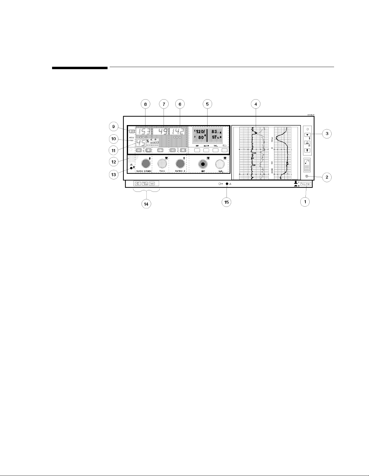
Overview of the Monitor
Figure 1-1 Major Parts
1. Monitor On/Off Switch 9. Function Key
2. Monitor On/Off Light 10. Telemetry Indicator
3. Recorder Keys 11. FSpO
4. Recorder 12. Opening Recess
5. Mate rnal Paramete rs 13. Socket for Remote Event Marker
6. Cardio 2 Channel 14. Setting Keys
7. Toc o Channel 15. Service Socket
8. Cardio 1/Combi Channel
parameter
2
General Information 9
Page 26
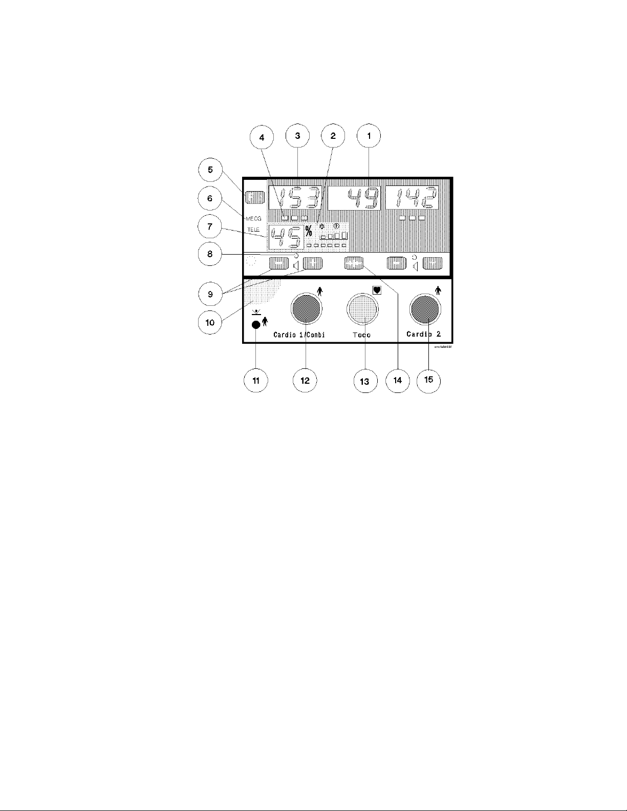
Cardio and Toco Channels
eta4.tif
Figure 1-2 Cardio and Toco Channels
1. Toco Display shows uterine activity.
2. Fetal SpO
display shows fetal pulse i ndi c ato r, signal quality, alarm status, and cross channel
2
verificati on pl us ind icator.
3. Cardio Display shows the FHR.
4. Signal Quality Indicator shows the quality of heart rate signal detected by the transducer:
• Green (optimum).
• Yellow (fair to potentially poor).
• Red (unaccep table).
5. Function Key selects menus for:
• FMP, twins offset, logic, FHR alert and FSpO
2
• returns to normal display.
6. MECG Indicator shows when MECG is being measu re d through this channel. (Indicat or
location different for Seri es 50 XM).
7. Fetal SpO
display shows current value of FSpO2.
2
8. Speaker Lamp shows which heartbeat is heard from the loudspeaker.
9. Volume Keys set the volume and select the channel to which you are listening. Changes
current setting of FMP, twins offset, logic, FHR alert and FSpO
alarms.
2
10. Recess for use when tilting the display.
10 General Information
Page 27

11. Remote Event Marker Socket for connecting remote event marker (15249A)
12. Cardio 1/Combi Transducer Socket. You can connect:
• FSpO
/ECG combined patient module (M1365A)
2
• ECG only patient module (M1364A)
• An ultrasound transducer (M1356A).
• A DECG transducer (M1357A).
• A US/MECG Combi transducer (M1358A).
• An MECG tra nsducer (M1359A).
13. Toco Transducer Socket. You can connect:
• An external Toco transducer (M1355A).
• An IUP transducer (1290C or M1333A).
14. Toco Baseline Key zeroes the Toco display and trace to 20 units (when monitoring uterine
activity externally) or 0 units (when monitoring uterine activity internally).
15. Cardio 2 Transducer Socket for connecting:
• ECG only patient module (M1364A)
• US transducer (M1356A)
• DECG transducer (M1357A)
• MECG transducer (M1359A)
General Information 11
Page 28
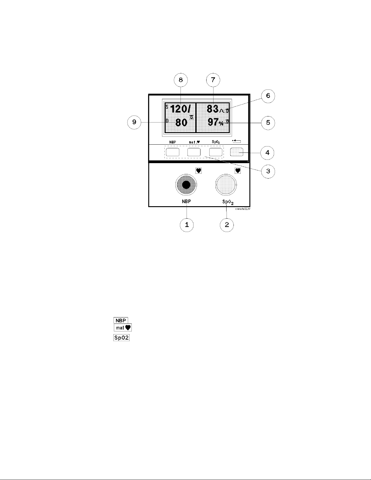
Maternal Parameters
Figure 1-3 Maternal Pa rameters
1. NBP Cuff Socket. You can connect:
• An NBP cuff interconnect tubing (M1599A) and cuff (M1574A).
2. SpO
Transducer Socket. You can connect:
2
• An SpO
transducer (M1940A adapter cable connected to M1191A transducer).
2
3. Softkeys for operating and setting maternal parameters. They are:
• selects modes and alarm limits for NBP.
• selects modes and alarm limits for MHR.
• selects modes and alarm limits for SpO
.
2
4. Reset Key (yellow)
One short press
• Acknowledges warning message
• Acknowledges alarm
One press, held for two seconds (from maternal main screen only)
• Accesses volume and contrast setup
Two presses within one second (from maternal main screen only)
• Displays current maternal alarm limits
5. SpO
Value indicates the current reading for patient's oxygen saturation level.
2
12 General Information
Page 29
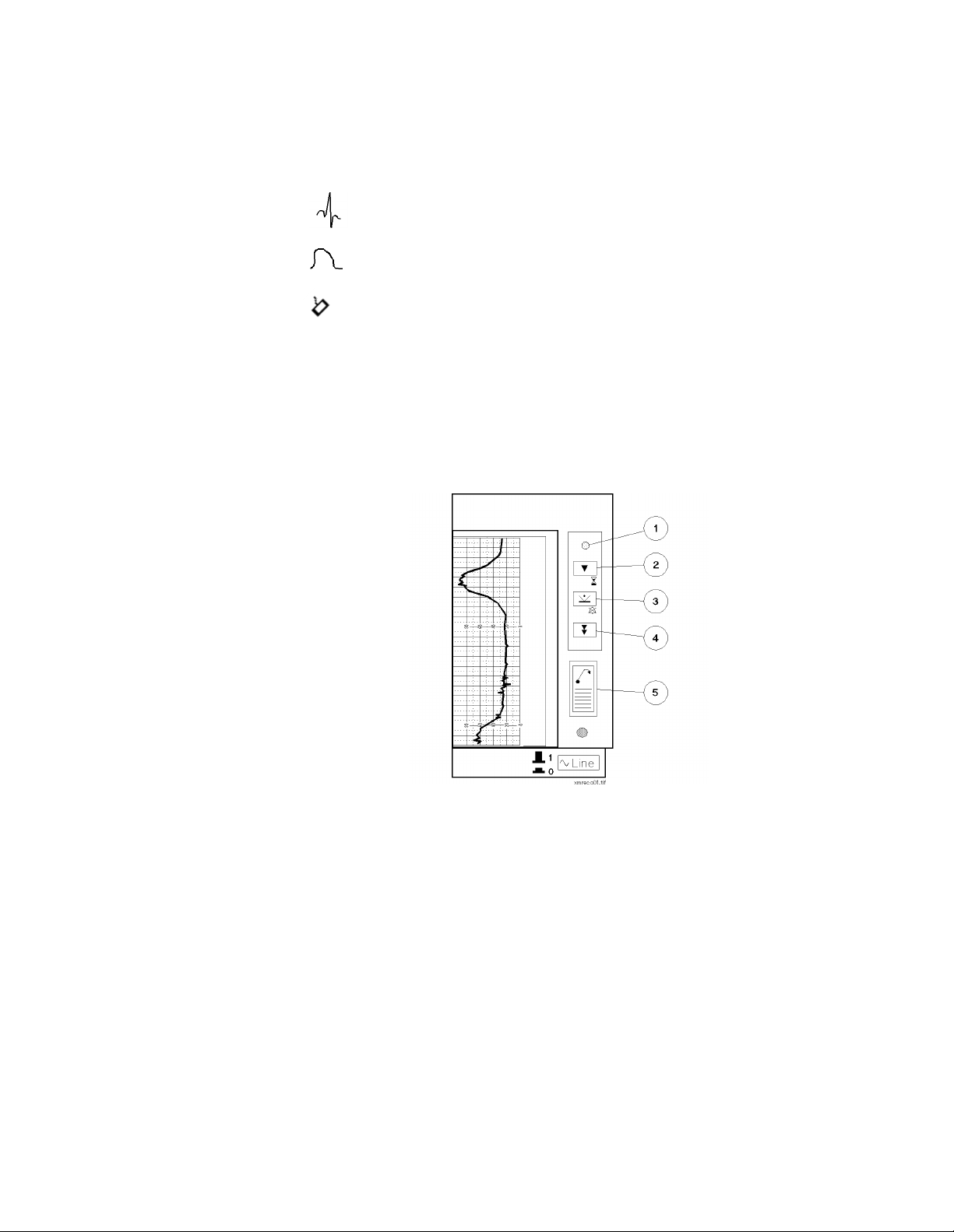
6. MHR Icon indicates source of MHR
indicates heart rate value taken from MECG measurement.
Recorder Keys
indicates pulse rate value taken from SpO
indicates average pulse rate taken from NIBP measurement.
7. Maternal Heart Rate shows current heart rate or pulse rate.
8. Systolic Value shows the value for the systolic parameter of the most recent external blood
pressure measurement.
9. Diastolic Value shows the value for the diastolic parameter of the most recent external blood
pressure measurement.
measurement.
2
Figure 1-4 Recorder Keys
1. Recorder On/Off Light. On when the recorder is switched on. Flashes when monitor detects
five or fewer pages remaining in the pack or if the paper runs out.
2. Recorder On/Off Key.
Single press turns recorder on/off
2-second press starts NST timer. Recorder must be off.
3. Event Marker Key. Press to record an event on the paper. Acknowledges all alerts and
alarms.
4. Paper Advance Key. Press once to advance the paper automatically to the next fold. Press a
second time to stop paper before fold. Tear paper at fold. Never pull pap er to adva nc e it.
5. Paper-Eject Key. Press once to unlock the drawer, and then press a second time and hold to
remove the paper.
General Information 13
Page 30
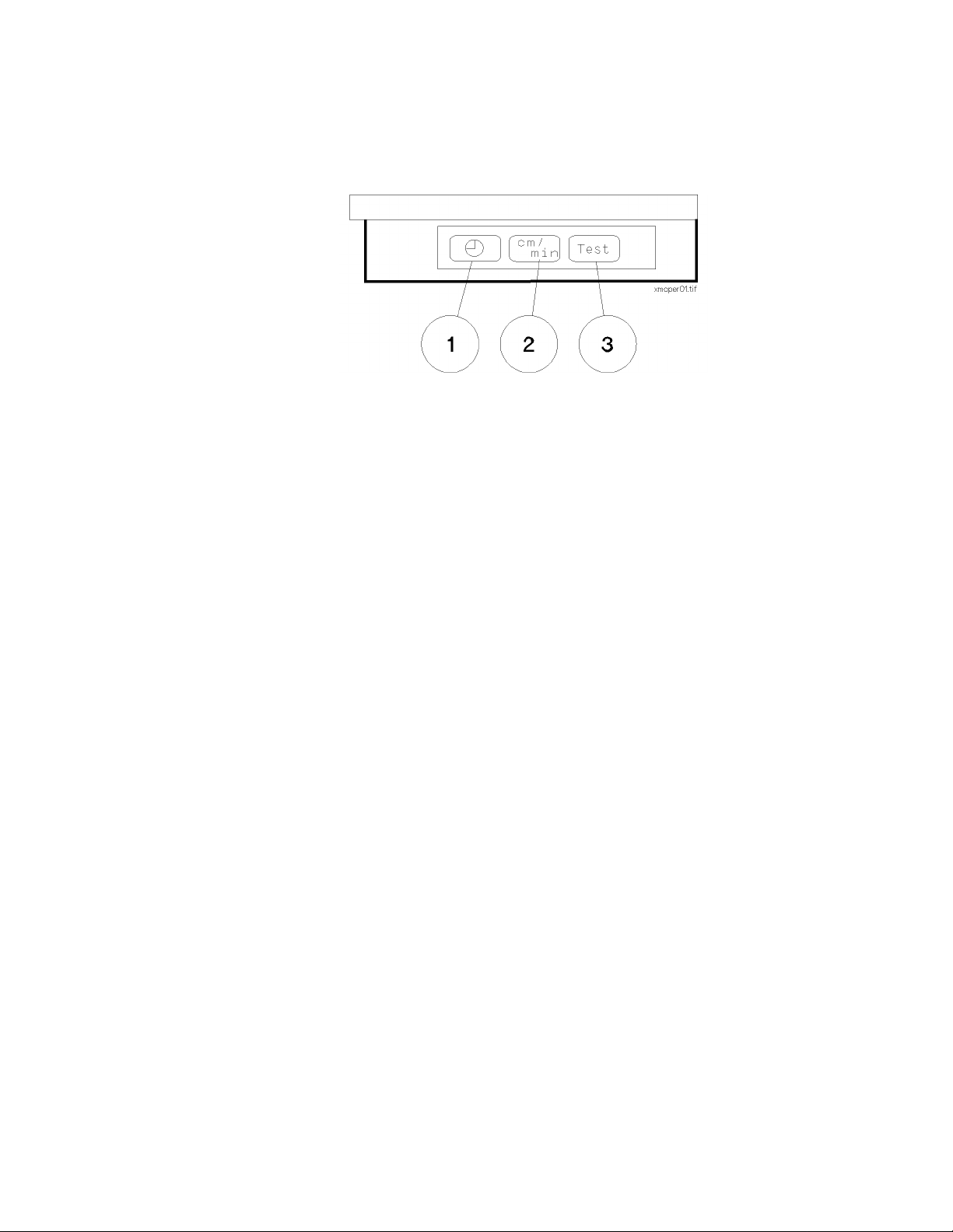
Setting Keys
Figure 1-5 Setting Keys
1. Time and Date Key. Used when changing the time and date. Press to show the current time
in the Cardio 1/Combi and Toco di splays, to cycle through the settings to be changed
(hours, minutes, day, month and year) and to return to the normal display.
2. Paper Speed Key. Used when changing the paper speed. Press to show the current paper
speed in the Cardio 1/Combi display, and to return to the normal display.
3. Test Key. Used to start monitor self test.
14 General Information
Page 31

Rear Panel .
10
21
Figure 1-6 Rear Panel
1. Power Cord Connection
2. Equi potential Grounding Point
3. ROM Board (M1350-66506)
4. Telemetry Interface Connector (M1350-66537) and System Interface Connector
(RS232) (lower)
5. Exte rnal Blood Pressure Board (M1350-66535)
6. Digital Signal Processor (DSPII) (M1350-66 507)
7. Maternal SpO
8. OBMS/ODIS Analog Interface (optional) (M1350-66532)
9. Dual Serial Interface (DSIF) (M1350-66533) External Fetal Pulse Oximeter or Adult
parameter Interface
10. CPU Board with Barcode Reader Interface (M1350-66513)
Board (M1350-66534)
2
3
456789
General Information 15
Page 32

16 General Information
Page 33

Power Source Requirements
The monitor can be operated fr om an ac sou rce of 10 0 to 120 or 220 to 240 volts (±10%) at 50 Hz
or 60Hz (±5%). The system will be set to the correct voltage at the factory.
Prior to installi ng the system, check that the systems vo ltage has been set corr ectly. The voltage and
fuse values are shown on the rear panel.
2
Pre-Installation Checks
Figure 2-1 System Voltage and Fuse Values on the Rear Panel
Caution
If the voltage has been set incorrectly you must reset it before you connect the system to the
local line power supply. See “Setting the Required Voltage” on page 2-18.
Pre-Installation Checks 17
Page 34

Setting the Required Voltage
1. Using a flat blade screwdriver, open the panel on the rear of the monitor.
pin1sca.tif
Figure 2-2 Opening the Rear Panel
2. Remove the voltage selector drum, turn it to the voltage required, and replace it.
pin2sca.tif
Figure 2-3 Voltage Selector Removal and Replacement
3. Close the rear panel and check that the correct voltage setting is shown (see 2-1).
18 Pre-Installation Checks
Page 35

Mounting the Monitor
You must carry out the pre-installation checks described in Chapter 2 before installing the
monitor.
The Series 50 XM/XMO Monitor can be mounted in a number of ways, for example:
n
Surface mounted
n
Cart mounted
n
Top mounted
3
Installing the Monitor
Surface
The XM/XMO can be rested on, but not fixed to, an existing surface.
Mounting
Cart Mounting There are three mobile carts (CL, CX, and CM) on which you can mount the Seri es 50 XM/XMO
Monitor. All offer a combined storage and transport unit for the monitor plus accessories and
ancillary equipment. See page 21 for carts specifications.
Top Mounting Top mounting Kit Number M1350-68701 allows you to mount auxiliary equipment on top of the
monitor (for example, the M1310A Telemetry Receiver). This equipment must be fitted with a
mounting cam kit to allow the equipment to be secured to the mounting plate.
To attach the mounting plate onto the monitor:
1. Remove the two blanking plugs from the top of the monitor.
2. Position the mounting plate on top of the monitor and insert the two screws.
3. Insert the two blanking plugs into the holes above the screws.
4. Clip the four plastic strips into the slots in the mounting plate. These are removed when the
ancillary equipment is moun ted on top of the monitor.
Installing the Monitor 19
Page 36

pin19sca.tif
Figure 3-1 Attaching the Mounting Plate
Fitting the Paper Take-Up Tray
You can fit a paper take-up tray (M1350-00452) to the base of the moni tor using the two pre fitted bolts located under the recorder modul e on the base of the monitor. Simply line up the
paper take-up tray slots and slide the paper tray into position.
Figure 3-2 Paper Take-Up Tray
20 Installing the Monitor
Page 37

Carts
You can mount th e Series 50 XM and the Series 50 XMO fetal/maternal monitors on the Philips
CL, CM or CX carts. Cleaning instructions for the carts and safety details are provided in the
Carts Equipment Note delivered with you r ca rt.
Table 3-1 Philips Carts: Specifications
Specifications
Width (mm) 514 614 614
Depth (mm) 625 625 625
Height (mm) 805 989 1117
Weight (kg) 24.2 50.6 63.4
Table 3-2 Philips Carts Replacement Parts
Carts
CL (M1323A) CM (M1234A) CX (M1324A)
Replacement
Parts
Wheels M1324-42100 ✘✔✔
Drawers M1324-68500 ✘✔✔
CAM Mounting
Arm Kit
Mounting Kit IUP
Pole
Infusion Pole
Mount
Mounting Rail Kit 5061-8365 ✔✔✔
Part numbers
M1323-42075 ✔✘✘
M1323-68450 ✔✘✘
5061-8340 ✔✔✔
80310-68701 ✔✔✔
5061-8364 ✔✔✔
Cart CL
(M1323A)
Cart CM
(M1324A)
Cart CX
(M1325A)
Installing the Monitor 21
Page 38

Barcode Reader
This section tells you how to connect and test the barcode reader (HBSW8200).
Attaching the Reader Holder
Connecting the Reader
To attach the barcode reader holder to the monitor:
1. Clean the surface of the monitor where you will attach the barcode reader holder thoroughly
using ethanol.
2. Peel off the backing from the adhesive strip on the holder, and press the holder firmly into
place.
3. Allow 24 hours before using the holder.
1. Plug the barcode r eader into the m onitor and se cure by turning the two thumb s c rews.
pin15sca.tif
Figure 3-3 Connecting the Barcode Reader
Testing the Reader
22 Installing the Monitor
After installing the barcode reader you must check that it is corr ectly connected to t he monitor and
that the monitor is configured to read the barcodes. You can do this using the barcodes printed
below or from your barcode booklet kit.
To do this:
1. Be sure that both the monitor and recorder are turned on.
2. Read the
3. Switch the monitor off then on. Read the TEST OK 5 barcode.
Default Configuration barcode.
Page 39

pegbscs1.tif
Figure 3-4 Test Barcodes
TEST OK 5 should be written on the recorder paper.
Figure 3-5 Test Annotation on the Recorder Paper
4. If the above test does not work, turn the monitor OFF and ON and repeat the test.
5. If the problem remains, connect a new Barcode Reader.
Installing the Monitor 23
Page 40

24 Installing the Monitor
Page 41

Introduction
4
Configuring the Monitor
This chapter describes the tasks you must carry out to configure the monitor. This involves the
following service tasks:
n
Configure the monitor
n
Configure the recorder
n
Print and clear the error log
n
Set the time and date format to the local standard
Some configuration tasks can be completed by connecting a PC to the monitor, some by using
pushbuttons on the monitor itself. Most can be performed using whichever method is more
convenient for you: see Table Table 4-1 for a list of tasks and methods. To find out how to set the
time, date, and paper speed, see Ch apter 5.
Configuring the Monitor 25
Page 42

Configuration Tasks
The following table shows you which configuration actions can be carried out using p us hbuttons
on the monitor and which can be carried out using a PC connected to the service socket.
Table 4-1 Configuring the Monitor
Configure the time format Yes Yes
Configure the date format Yes Yes
Configure the IUP format Yes Yes
Configure the paper format Yes Yes
Configure the recorder print offset Yes Yes
Configure the recorder heat adjust Yes Yes
Alert acknowledgment at marker button Yes No
Task Buttons PC
Run the cyclic test
No
1
No
Read the options installed No Yes
Read the Error Log No Yes
Print the Error Log
Clear the Error Log
Yes
Yes
2
2
Yes
Yes
Write the serial number and set the options No Yes
Configure the language option Yes No
Enable alert acknowledgement Yes No
Note Output to System Yes No
NIBP paper save mode Yes No
MECG trigger click volume Yes No
response time Yes No
FSpO
2
FSpO
Inop alarm Yes No
2
FSpO
alarm volume Yes No
2
1. However you can run the Permanent Test, which is similar. See “Printing and Clearing the Error Log” on
page 30.
2. See “Printing and Clearing the Error Log” on page 30.
26 Configuring the Monitor
Page 43

Configuring the Monitor Using Pushbuttons
You can set the time format, date format, IUP scale, paper format, recorder scale offset, recorder
heat and language option using pushbuttons. To change a setting:
1. Disconnect all transducers from the Monitor and disconnect or switch off Telemetry.
2. While pressing , press . The display shows
or
1 in the Toco display.
C01 in the US1/US display and 0
3. Toggle through t he menu by pressing or until you arrive at the menu item you
want to change. The menu items and their settings are shown in TableTable 4-2.
4. Press to change the setting (
0 or 1).
5. Press to store the new settings. If yo do not press any keys for about 15 seconds,
the settings will be automatically stored.
Table 4-2 Configuration Options
Menu Setting Options Default
C01 Time Format 0=AM/PM
1=24-hour
C02 Date Format 0=US (month/day/year)
1=Europe (day.month.year)
C03 IUP Format 0=mmHg
1=kPa
C04 Paper Format 0=US (30-240)
1=Europe (50-210)
C05
Recorder Print Offs et
0 to 11
1
0=right
11=left
1
0
0
0
0
C06 Recorder Heat Adjust
0 to 11
C07 Language Option 1=US International
C08
C09 Note Output to System
C10 DSIF Refer to Table Table 4-3 0
Recorder Marker
(Roman 8)
2
0=minimum
11= maximum
2=French
3=German
4=Dutch
5=Spanish
6=Italian
10=Japanese
13=Chinese (simplified)
17=Russian
0=normal
1=system acknowledge
0=transmission off
1=transmission on
0
1
0
1
Configuring the Monitor 27
Page 44

Table 4-2 Configuration Options
Menu Setting Options Default
C11 External Toco gain 0=100% External Toco gain
1=50%
C12 Refer to Table Table 4-5
C13 OBMS and Telemetry/
System boards
3
0=RS422 System Inter face on OBMS
board active
1=RS232 System Inter face on
Telemetry/System board active
C14 Analog fetal movements 0=off
1=on
C16 NIBP paper save mode 0=off
1=on
C17 MECG trigger click volume 0=off
1=quiet
2=medium
3=loud
C18
(XMO only)
C19
(XMO only)
C20
(XMO only)
response time
FSpO
2
FSpO
Inop alarm 0=off
2
FSpO
alarm volume 0=off
2
4
0=slow
1=fast
1=on
1=quiet
2=medium
3=loud
0
0
0
0
2
1
0
2
1. To find the correct setting, connect a Toco transducer to the monitor and then change the setting until the
trace is recording 20 units on the paper. Because of the 8-second time-out fea ture, and the delay between
changing the se tting and seeing the cha n ge on the paper, you may have to repeat this procedure to set the
offset.
2. If the alert acknowledgement function is on, the fetal monitor adds the alert acknowledgement function on
the recorder marker button. Thi s ale r t ackn ow led g ement is given only to the central station after a request
from the central station (communication is via the digital interface.)
3. With this setting you can switch the control between the RS232 port on the new Telemetry/System board
M1350-66536 and the RS422 port implemented on the System Interface board M1350-66532. If only one
of them is built into the fetal monitor this one will be active regardless of the setting.
4. Response mode is an output-average filter. You can select whether the monitor averages samples over a short
time (approxima tely 10 seconds) or lon ger period (approx imately 50 second s). The times var y according to
the heartrate and signal quality and those quoted here are val i d f or go od signal quality and a heartrate in the
120 bmp range. The fast response mode, because it requires fewer samples, allows you to see sudden changes
in output mo r e e a sily. Fast response m o d e is indicated on the trace by .
28 Configuring the Monitor
Page 45

Table 4-3 Service Setting C10 Options (DSIF Configuration Options)
Connector 1 (9pin) Connector 2 (25 pin) C10 Option
See Table Table 4-4
Dinamap 1846/8100 Nellcor N-200 1
Colin BP-8800 Nellcor N-200 2
78352/4C Nellcor N-200 3
Accutorr - all models Nellcor N-200 4
Philips CMS, all models
Philips 26/24 Series
Dinamap 1846/8100 Nellcor N-400 11
Colin BP-8800 Nellcor N-400 12
78352/4C Nellcor N-400 13
Accutorr - all models Nellcor N-400 1 4
Philips CMS
Philips 26/24 Series
1
Nellcor N-200 5
Nellcor N-400 15
0
1. The service setting C10=0 ensures the co mpatibility of ol der monitors with external
devices and will not normally be needed with the M1350B and M1350C
Table 4-4 Service Setting C10 = 0 (DIP Switch Settings on the DSIF Board)
Connector 1
9 pin female
Dinamap 1846
(600Bd)
Philips CMS and
Philips 26/24 Series
(9600Bd)
Accutorr
(9600Bd)
Colin BP-8800
(4800Bd)
78352/4C
(9600Bd)
Connector 2
25 pin female
Nellcor N-200
(2400Bd)
Nellcor N-200
(2400 Bd)
Nellcor N-200
(2400Bd)
Nellcor N-200
(2400Bd)
Nellcor N-200
(2400Bd)
12345678
sssssXXX
▼ ▲ ▲ ▲ ▲ X X X
▲ ▼ ▲ ▲ ▲ X X X
▼ ▼ ▲ ▲ ▲ X X X
▲ ▲ ▼ ▲ ▲ X X X
Switch Settings
Configuring the Monitor 29
Page 46

Table 4-5 Service Setting C12 Options
Printing and Clearing the Error Log
NST Timer
No No No 0
Yes No No 1
Yes Yes No 2
No No Yes 3
Yes No Yes 4 (default)
Yes Yes Yes 5 (Japan)
To print or clear the error log:
1. Disconnect all transducers from the monitor and disconnect, or switch off, Telemetry.
2. Make sure the recorder is on.
3. While pressing press
•
C01 is shown in the US1/US display.
• 0 or 1 is shown in the Toco display.
Auto Recording
Off
Acoustic Paper
Out Alert
Option \
Number
4. Press again to select the Function Menu:
A01 (Print the Error Log) i s shown in th e US1/US dis play.
•
To print the Error Log, press . The display shows nnn nnn nnn.
• Press again to select
To clear the Error Log, press . The display shows nnn nnn nnn.
30 Configuring the Monitor
A02 (Clear the Error Log).
Page 47

The following shows an example of an error log
Table 4-6 Example of an Error Log
506 0005 98/09/14 11:27 98/09/14 16:53
FIC
0540 0008 98/09/14 11:27 98/09/14 16:54
E1C6 0005 98/09/14 11:27 98/09/14 16:53
021A 0002 98/09/14 16:24 98/09/14 16:25
OPTIONS FMP UStwin, Fet.Alert,
DATE: SW_REV INSTR_ID
95/09/15/ C.01.00 M1350C 2445G35213
BOARDS
Pos. 00 515 ID_2
Pos. 01 502
Pos. 02 506
Pos. 03 513
Pos. 04 536 ID_2
Pos. 05
Pos. 06
Pos. 07 507
Pos. 08
Pos. 09
Pos. 10 540
Pos. 11
SERVICE SETTINGS:
C01 01
C02 01
C03 00
C04 00
C05 00
C06 02
C07 03
C08 00
C09 01
C010 02
C011 01
C012 02
C013 00
C014 00
C016 01
C017 00
C018 01
C019 00
C20 00
FSP02 SW_REV:
NBP FMHP 5.0.1
NBP FSPO2 ERRORS:
540 0002 98/09/14 11:27 98/09/14 16:53
Configuring the Monitor 31
Page 48

The error log is divided into seven sections that contain the following information:
Section 1
1. The error code
For example 506
2. The number of times the error has occurred.
For example 0005 (note that the error counter uses hexadecimal notation)
3. The date and time the error first occurred.
For example 98/09/14 11:27
4. The date and time the error last occurred.
For example 98/09/14 16:23
The remaining lines in section 1 (if any) beneath the factory information code (FIC) are not
errors. Take no action.
Section 2
All built in options in the fetal monitor are written. For example Fet.Alert indicates fetal alerting.
Section 3
This shows information about t he monitor itse lf:
DATE SW_REV INSTR_ID
Current date
1
Software revi sion Product numbe r
and monitor serial number
1. This is taken fr om the monitor’s internal clock.
Section 4
The final three digits of all boar ds connected into the feta l monitor. For example in Pos. 05 is boar d
M1350-66536.
Section 5
The complete configuration made using the monitor’s push buttons is listed for easy validation
and documentation.
Section 6
The revision number of the FSpO2 software.
Section 7
The error code, occurrences, and times and dates thereof are shown specifically for the FSpO2
board in exactly the same way as other boards are displayed in Section 1 of the error log.
32 Configuring the Monitor
Page 49

Changing the Time Format
To change the time fo r ma t from AM/PM format to 24-hour format, do the following:
1. Disconnect all transducers from the Monitor and disconnect or switch off Telemetry.
2. While pressing press .
3. Press to change the setting to
4. Press
Full details about changing the time and date formats are given in Chapter 5.
Test to store the new settings.
Configuring the Monitor Using a PC
The service software kit (M1360C Option 875, part number M1360-6 887 5) allows you to carry
out various ext ended configuration and serv ice functions on the monitor. Contact your Ph ilips
Sales Office for details.
The service software disk can be run on an i ndust ry standard PC. There is also an adapter cabl e to
connect the monitor to the PC.
1.
Figure 4-1 Cable for an Industry Standard compatible PC
Configuring the Monitor 33
Page 50

Installing the Service Program
Before you install the program, ensure that the serial port COM1 is set up as follows:
Transmission Rate 9600 BPS
Parity None
Word length (bits) 8
Stop-bits 1
Serial Interface
Connection
This is done by giving the mode command (
Refer to your MS-DOS Manual for details.
To ins tall the program:
1. Switch on the PC.
2. Create a directory for the program files. For example, to create a directory called
at the DOS prompt type in:
md service
and press .
3. Insert the program disk into drive A.
4. At the DOS prompt type
5. At the
Make sure that the serial interface configuration on the PC is set up as follows:
A: prompt, type:
copy pegserv.exe c:\service
and press . Where service is the directory you created to contain the program files.
The program is copied to
Datacom-Configuration
Parameter Serial
Transmission Rate (BPS) 9600
Word Length (bits) 8
Stop-Bits 1
Parity None
%ON / %OFF Pacing Off
CTS Line Regard
DSR Line Regard
DCD Line Ignore
Power to Interface Off
A: and press .
c:\service
mode com1:96,N,8,1) at the DOS prompt.
service,
34 Configuring the Monitor
Page 51

Connecting the PC to the Monitor
Connect the cable from the PC to the service socket (1). If you are using an HP PC, use only the
COM1 port.
xmofull1.gif
Figure 4-2 Service Socket
Loading the Service Program
1. Switch on both the m o nitor and the PC.
2. No w load the program.
If you are using the PC in DOS mode, do one of the following.
• If the program files are contained in a directory, change to that directory and enter:
pegserv
• If you want to load the program from drive A (or another drive):
i. Insert the program disk into drive A (or other).
ii. Select
iii. At the DOS prompt type
iv. Type
If you are using Windows 95/98/NT:
• Start the service program by double-clicking on the
pegserv.exe
3. The program is now loaded and ready for use.
DOS-Commands and press .
A: and press .
pegserv and press .
pegserv icon or on the filename
Configuring the Monitor 35
Page 52

Using the Service Program
When the program has been loaded onto your PC, th e main menu is displayed. (If the menu is not
displayed, an error message is displayed along the bottom of the screen.)
Main Menu
Series 50 Fetal Monitor Configuration and Service Software Rev A.nn.nn
MESSAGE:
Select with >cursor keys< or >E, S, D, X< then press <ENTER> to execute!!
Main Menu
Configuration Settings
Recorder Adjustments
Service Menu
Exit
To select an item from the menu, move the cursor to the item you require and press :
n
Use the arrow keys , , , keys on the keypad, or the E, S, D or X keys to
move the cursor.
Messages are displayed along the bottom of the screen while the Service Program is working, for
example:
Reading Recorder Adjustments from the Monitor.
Reading Serial Number from the Monitor.
Clearing the Error Log.
36 Configuring the Monitor
Page 53

Configuring the Monitor
Series 50 Fetal Monitor Configuration and Service Sof tware Rev A.nn.nn
Configuratio n Setting:
Function : Actual Se tting is Select
Paper Scale : US US EU
Time Format : AM/PM AM/PM 24h
Date Format : US US EU
IUP Scale : mmHg mmHG kPA
MESSAGE:
Select with >cur sor keys< or >E, S, D, X< then press <ENTER> to ex ecute!!
To change a setting:
1. Using the appropriate keys, move the cursor to the selection you require.
2. Press .
To return to the Main Menu:
1. Move the cursor to
Return to Main Menu.
2. Press .
Example
On the screen above, the actual setting of the paper scale is
cursor to
EU in the Select column and press . The program will reconfigure the monitor
US. To change this to EU, move the
for the European paper scale.
The settings on your monitor may be different from those shown.
Configuring the Monitor 37
Page 54

Adjusting the Recorder
The Recorder Heat-Adjust is to compensate for different tolerances in the paper.
Series 50 Fetal Mo nitor Configuration and Service Software Rev A.nn.nn
Recorder Adju stments:
Recorder Heat Adjust: Actual Value is: |
Recorder Zero Adjust: Actual Value is: |
Return to Main Menu
MESSAGE:
Select with >cursor keys< or >E, S, D, X< then press <ENTER> to execute!!
Selected Value is |
∨
|……………|
Min Max
Selected Value is |
∨
|……………|
Left Right
To change a setting:
1. Using the appropriate keys, move the cursor to the new value you require.
2. Press .
To return to the Main Menu:
1. Move the cursor to
Return to Main Menu.
2. Press .
Example
On the screen above, the actual value of the recorder zero-adjust is
Left. To change this to
Right, move the cursor to Right in the Selected Value is: column and press .
The program will adjust the recorder accordingly. The values shown on your monitor may be
different from those shown.
38 Configuring the Monitor
Page 55

Service Menu To select an item from the menu, move the cursor to the item you require and press .
Note Before you select
the monitor.
The serial number and software revision of your monitor may be different from those shown.
Series 50 Fetal Mo nitor Configuration and Service So ftware Rev A.nn.nn
Serial Number : 2948G00010
Software Revision : A.02.03
MESSAGE:
Select with >cursor keys< or >E, S, D, X< then press <ENTER> to execute!!
Cyclic Test, you must connect ultra sound , Toco and DECG transducers to
Service Menu
Cyclic Test
Read options
Read ErrorLog
Clear ErrorLog
Write Ser.nr./ Set Options
Fetal Heart Rate Alerting
Return to Main Menu
Running the Cyclic
Test
The Cyclic Test is a continuous Self Test. Any errors are written to the Error Log and can be read
using
Read ErrorLog. Press any key to stop the test and return to the Service Menu. During
the test the keys on the front of the monitor are disabled.
Series 50 Fetal Mo nitor Configuration and Service Software Rev A.nn.nn
CYCLIC TEST is st arted
It starts a contin uous self test of the monitor
Press any key to sto p this test
Read ErrorLog to see the errors that occurred while self testing
MESSAGE:
Configuring the Monitor 39
Page 56

Reading the Options This lists the options installed on the monitor. Press any key to return to the Service Menu. The
options on your monitor may be different from those shown.
Series 50 Fetal Monitor Configuration and Service Software Rev A.nn.nn
Implemented Options :
- Fetal Movement Profile
- External Twin Monitoring
MESSAGE:
Press any KEY to continue!
Reading the Error
Log
This displays the error log. (See Chapter 11 for a list of error log messages.)
> PAGE 1 < Errorlog of : 2948G00010
Err. Count 1st Date+Time last Date+Time
Code nnnn yy/mm/dd HH:MM yy/mm/dd HH:MM
|-| |--| |------.----| |------.----|
Use >W< to Write ErrorLog Data to File >ErrLog.DAT<
use CursorKey >Down< or >X< to see next Page, <ENTER> to leave
The error log lists:
n
The monitor’s serial number.
n
The error code and the number of times the error has occurred.
n
The date and time the error first occurred.
n
The date and time the error last occurred.
Up to 16 err or messages can be displa yed on a screen. To see the next or previous screen, use the
▼ keys on the keypad, or the E or X keys. At the end of the Error Log, No more Data
or
▲
40 Configuring the Monitor
Page 57

available is displayed.
Clearing the Error
Log
Press
to print a page on LPT1.
Press to return to the Service Menu.
To write the error log data to a file, press the W key. The data is then stored as
the directory con taining
the file can be printed using the DOS Command
PEGSERV.EXE. The data is stored as ASCII characters, and therefore
print ERRLOG.DAT. The file is overwritten
each time you press the W key.
Series 50 Fetal Mo nitor Configuration and Service So ftware Rev A.nn.nn
Service Menu
Serial Number : 2948G00010
Software Revision : A.02.03
Cyclic Test
Read options
Read ErrorLog
Clear ErrorLog Are you sure?
Write Ser.nr./ Set Options
Fetal Heart Rate Alerting
MESSAGE:
Select with >cursor keys< or >E, S, D, X< then press <ENTER> to execute!!
Return to Main Menu
ERRLOG.DAT in
The confirmation message
n
Press Y to clear the error log, OR
n
Press N.
Are You Sure? asks if you do want to clear the error log:
You then return to the Servic e Menu.
Configuring the Monitor 41
Page 58

Writing the
Serial Number
You can write the serial number to the monitor only if you have replaced the CPU Board with an
exchange board. The serial number can be written only once to the exchanged board. If you
accidently enter the wrong serial number, you can reset it us ing an access code obtainable from
your Philips Response Center or from the Philips Technical Marketing Intranet page, “Softserver.”
Series 50 Fetal Mo nitor Configuration and Service So ftware Rev A.nn.nn
NOTE: resettin g the Serial Number is protected by Access Code
Serial Number : 3151G00026
Type in 4 digit code from factory TME and press <ENTER>
MESSAGE:
>----<
To write the serial number:
1. Using the keyboard, type in the serial number of the monitor. This is printed on the side and
on the bottom of the monitor
2. Press .
A confirmation message asks if the serial number is correct:
• Press Y if it is, OR
• Press N and retype the serial number.
You then go to the Set Options Screen to reset the options for the monitor.
42 Configuring the Monitor
Page 59

Series 50 Fetal Mo nitor Configuration and Service So ftware Rev A.nn.nn
Select Options according to the labels on the monitor
Option: Actual Setting is : Selection:
#C.01 TWIN: OFF OFF ON
#C.02 FMP: OFF OFF ON
Write Options
MESSAGE:
Select with >cursor keys< or >E, S, D, X< then press <ENTER> to execute!!
To select an option:
1. Using the appropriate keys, move the cursor to the selection you require.
2. Press .
To write the options to the monitor and return to the Main Menu:
1. Move the cursor to
Write Options.
2. Press .
A confirmation message asks if the selected options are correct.
Configuring the Monitor 43
Page 60

Enabling/
Disabling FHR
Alerting
This screen enables you to enable or disable the fetal heart rate alerting. To change this
configuration you must enter an access code, which is availabl e from your Philips R esponse Center
or from the T echnical Marketing “Softserver” page on the Philips Intranet. There are two different
access codes, one enables the alerting, and the second disables alerting.
Series 50 Fetal Mo nitor Configuration and Service So ftware Rev A.nn.nn
NOTE: Changin g the Alert Option is protected by Acces s Code !
Alert Option is EN ABLED. Do you want to DISABLE the Alert option?
Press <Y> for YES or <N> for NO!
MESSAGE:
To enable or disable the alerting, enter the specific code to enable or disable the alerting.
44 Configuring the Monitor
Page 61

Getting Started (Basic Considerations
Setting the Time and Date
You can view and change the time, the date and the paper speed using the following keys:
Figure 5-1 Setting the Time and Date
5
and Operation)
n
Clock key displays the time (1).
n
Paper speed displays the paper speed (2).
n
Volume keys change the time, date and paper speed (3).
To set the time and date:
1. Press and release to display the current time. The Cardio 1/Combi display flashes to
show that the hour can be chan ged.
2. Press or to set the hour. Press and hold the keys to change the setting more
quickly.
3. Press and release and the Toco display flashes to show that the minutes can be
changed.
4. Press or to set the minutes.
5. Repeat the procedure:
• To set the month (in North America) or the day (in other countries).
• To set the day (in North America) or the month (in other countries).
• To set the year.
6. Press and release to return to th e normal disp lay.
You can also change the format of the time and date using the optional Barcode Reader and the
feature setting barcodes supplied with it.
Getting Started (Basic Considerations and Operation) 45
Page 62

Changing the Time Format
To change from 12-hour to 24-hour format, enter
TIME FORMAT 24H (MILITARY) from the feature setting sheet.
To change from 24-hour to 12-hour format, enter
TIME FORMAT AM/PM from the feature setting sheet.
To change from Day.Month.Year to Month/Day/Year format, enter
DATE FORMAT NORTH AMERICAN from the feature setting sheet.
To change from Month/Day/Year to Day.Month.Year format, enter
DATE FORMAT EUROPEAN from the feature setting sheet.
If the batteries are not changed when they become low or empty of charge, the settings will return
to their def ault values: th e date is set to 04.04.44 and the time is set to either 00.00 (European
Format) or 12:00A (US Format).
Setting Paper Speed and Scale
Setting the Paper Speed
The paper speed can be 1, 2 or 3 cm/min. The default for North America is 3 cm/min; the default
for other countries is 2 cm/min. A change in paper sp eed wil l r e sul t in a chang e in the app earance
of an FHR trace, care must be taken to ensure ALL monitors in your institution are consistently
set at the same speed.
The ACOG technical bulletin on FHR monitoring states that “accurate pattern recognition is
difficult if not impossible at 1 cm/min and that 1 cm/min is only recommended for more
economic screening. When FHR abnormalities arise, the faster paper speeds will enhance FHR
pattern recognition.”
Use the Paper Speed Key to display the current paper speed and to return to the normal display.
You also return to the normal display automatically if you don't press any key for a few seconds.
When you return to the normal display, the new paper speed is set, and the time, date, speed and
monitoring modes are printed on the paper.
To set the paper speed:
1. Press and release to display the current speed.
2. Press or to set the speed.
3. Press and release to return to th e normal disp lay.
46 Getting Started (Basic Considerations and Operation)
Page 63

Setting the FHR Paper Scale
All chart paper available for the monitor is 2-channel chem/thermal paper, containing 150
numbered pages p er p ack . E ac h p age i s 10 0mm lo ng a nd 151mm wide. Sever al c o nf igu rations are
available, each with a 0 - 100 labor scale.
Table 5-1 Types of Trace Paper Available
Product
Numbe
r
M1910A 30 - 240 Orange No 4 0 No Yes
M1911A 50 - 210 Green No 40 Yes No
M1913A 50 - 210 Green No 40 No Yes
Caution
Using recorder paper that is not approved by Philips can damage the monitor. This type of
damage will not be covered by warranty.
Some monitor configurations come with a fetal monitoring record (FMR) management system.
Included in the FMR system are labels that facilitate a total management system for organized
storage and retrieval of patient records.
If you wish to use paper with a different FHR scale (for example, 50 - 210 bpm instead of 30 - 240
bpm) you can change the paper scale settings:
1. Using the service software (see “Using the Service Program” on page 4-36).
2. Using pushbuttons (s ee “Configuring the Monitor Using Pushbuttons” on page 4-27).
FHR
Scale
Color
of
Grid
FMR
Filing
System
Packs
per Case
Europea
n
KPa
scale
Highlighte
d
Three
Lines
Getting Started (Basic Considerations and Operation) 47
Page 64

Switching Logic Off and On
The default setting for arrhythmia logic is on. To change the setting, do the following:
n
Connect a DECG transducer to the Cardio 1/Combi or Cardio 2 socket.
n
Press repeatedly until is displayed.
n
The Signal Quality Indicator shows:
• RED if logic is OFF.
• GREEN if logic is ON.
n
Press or to change the setting.
n
Press repeatedly to return to the normal display.
You also return to the normal display automatically if you do not press a key for a few seconds.
Separating FHR Traces (“Twins Offset”)
To help with the interpretation of traces with similar baselines, you can separate them.
Using Keys
Using the
Barcode Reader
n
Connect two fetal heart rate transducers to the Cardio 1/Combi and Cardio 2 sockets.
n
Press repeatedly to display .
n
The Signal Quality Indicator shows:
• RED if the traces are NOT SEPARATED.
• GREEN if the traces are SEPARATED.
n
Press or to change the setting.
n
Press repeatedly to return to the normal display.
You also return to the normal display automatically if you do not press a key for a few seconds.
Enter “Twins Offset'' from the barcode sheet.
48 Getting Started (Basic Considerations and Operation)
Page 65

Switching FMP Off and On
The default setting for FMP is on. (FMP is an option.)
Using Keys To change the setting, do th e following:
n
Connect a transducer to the Cardio 1/Combi socket.
n
Press repeatedly until is displayed.
n
The Signal Quality Indicator shows:
• RED if FMP is OFF.
• GREEN if FMP is ON.
n
Press or to change the setting.
n
Press repeatedly to return to the normal display.
You also return to the normal display automatically if you do not press a key for a few seconds.
Using the
Barcode Reader
Enter
FMP Off or FMP On from the barcode sheet.
Getting Started (Basic Considerations and Operation) 49
Page 66

50 Getting Started (Basic Considerations and Operation)
Page 67

Monitor Rear Panel
6
System Interfaces
Figure 6-1 Sockets for Peripheral Devices
1. Interface for optional barcode reader.
2. Interface for Philips Series 50 T Fetal Telemetry System (M1310A) and external device. See
“Connecting External Devices” on page 62 and “Interface for Philips M1310A” on page 52
for details.
3. System interface for connection to 80225A/80235A OBMS System and/or M1340A Fetal
Trace Transmitter or M1370A ODIS System (optional). See “System Interface Option J12”
on page 59 for detai ls.
4. Serial RS232/RS422 system interface for connection of maternal monitors such as Philips
CMS. See “RS232 Dual Serial Interface Option J13” on page 61 for de tails.
5. RS232 digital syste m interface for connection to a Ph ilips OB TraceVue system or an IBM
compatible PC. See the table “Telemetry Interface: Pin Connections” on page 53 for details.
6. Serial RS232/RS 422 system inte rface for con nection of Nellcor N-200 maternal SpO
monitor (and N-400 fetal SpO
See “Rear Panel” on page 1-15 for a table of the board-slot positions.
System Interfaces 51
monitor for an M1350 XM without fetal SpO2).
2
2
Page 68

Interface for Philips M1310A
The Telemetry input allows connection to the Phil ips Fetal Telemetry Systems . Full functionality
is provided by the Philips Series 50 T Fetal Telemetry System (M1310A) and monitor software
revision higher than A.04.00.
The pin allocations for the various signals are shown below.
printelem.hpgl
Figure 6-2 Telemetry Input Signal Allocations
52 System Interfaces
Page 69

Table 6-1 Telemetry Interface: Pin Connections
Pin Signal Function 1 (Telemetry)
Function 2 (External
Parameter)
1 HR2 HR-LF 2 MECG Analog: Input
2 -12V Max. 100mA: Output
3 +5V Max. 100mA: Output
4 +12V Max. 100mA: Output
5S1
6S2
S3
Telemetry on (L)
DECG Inop (L)
1
:Input
1
Ext Par On (L)
1
INOP (L)1: Input
: Input
8 S4 DECG Mode Ext Par Code MSB (scaling): Input
9 S5 Reserved Mode Ext Par Code LSB (scaling): Input
10 S6
11 S7
12 S8
13 S9
US Mode (L)
IUP Mode (L)
Toco Ext Mode (L)
1
: Input Cardio Channel (L1): Input
Toco Channel (L
1
1
Input
1
): Input
14 HR1 (HR-LF) FHR low frequency 1
15 Toco Toco dc: Input
16 E xt Par Ext Par Analog: Inpu t
17 Gnd Analog Signal Gnd Signal Gnd
18 Gnd
19 Mark
Telemetry Marker on (L)
1
20 FMP on Telemetry FMP on
21 FM T elemetry Fetal Movemen t event on
22
reserved (L)
1
23 N. C. (if ID) New Interface= Do not
connect
Old Interface= connect to Gnd
24 Gnd
25 S10
HR2 Mode = MECG Mode (L)
1
1. If pin 5 is high (telemetry is off) the other inputs have different functions. Tele On (pin 5=L) and Ext.para.on
(pn 6=L) are not allowed at the same time.
HCMOS threshold:
L = Low = 0 to 1.5V
H = High = 3.5 to 5V
System Interfaces 53
Page 70

Ext. Par. Code Recorder Toco scale Recorder Philips sca le (US) (EU)
MSB LSB Sensit ivity 0..100 Sensitivity 30..240 50..210
0 0 1V/100 units 0V 1V 1V/100bpm 0.0V 2.1V 0.0V 1.6V
0 1 1V/100 units 0V 1V 1V/100bpm 0.3V 2.4V 0.5V 2.1V
1 0 2V/100 units -1V 1V 1V/100bpm 0.0V 2.1V 0.0V 1.6V
1 1 10V/100 unit -5V 5V 1V/100bpm 0.0V 2.1V 0.0V 1.6V
Functions for External Parameter Input
Telemetry Pin 1 HR 2--ME CG Anal og In put .
Analog Signal Specification:
n
Ri > 10 kΩ
n
U max = ±6 Vpp, min = 40 mVpp
MECG Mode (L) Input (pin 25) should be set to L (0V).
Pins 2, 3 and 4. Supplies for small peripheral instruments, eart h connecti ons t hro ugh pins 18 a nd
24. Maximum current allowed 100mA.
Pin 5 (S1) Telemetry on (L). monitor goes to Telemetry Mode.
n
Telemetry display field is lit.
n
Transducer must be removed from the front panel connectors. If they are not removed,
appears in the display above the transducer socket.
n
Status bits pin 7 (S3) to pin 13 (S9) and pin 25 (S10) are activated through the connection
to ground (p ins 18 to 24 ) and have function 1 (Telemetry).
n
Pin 6 (S2) must be High, if not appears in the display.
n
Each transition of S1 starts a complete mode annotation at the recorder.
Pin 7 (S3) DECG inop.
Pin 8 (S4) DECG Mode.
Pin 9 (S5) Reserved Mode.
Pin 10 (S6). US-Heart rate mode programming for Telemetry input signal.
Pin 11 (S7). Not used with Telemetry.
Pin 12 (S8). IUP Mode (L).
Pin 13 (S9). Toco Ext Mode (L). Toco mode programming. Activated Toco mode will be
displayed on the front panel.
54 System Interfaces
Page 71

Pin 14 HR 1 Fetal Heart Rate INPUT. Input signal depends upon the selected HR mode. The
table below gives details of the input signals for each of the HR modes.
Fetal Heart Rate Mode Input signal Pin 14
US (S6 Low leve l) Doppler LF sig n a l
Ω
Ri > 10 k
Umax = ±3.5 Vpp
min = 35 mVpp
Pin 15 TOCO - DC INPUT
External Parameter
Ri > 10 k
Ω
Input range = -3 V to +2 V
Sensitivity = -1 V Full scale
Pin 17. Signal ground for pins 14 and 15.
Pin 18 - 24. Ground for supply and status bits S1 to S10 activation. System outputs will be
controlled in the telemetry mode as in the front mode.
Pin 25. MECG - Mode. Input > (L). MECG mode programming. Activated MECG mode will
be displayed on the front panel. The input signal from pin 1 (MECG Analog Input) will be
processed by the instrument.
Pin 6 (S2) External Parameter ON (L). The external parameter is printed on the recorder in
addition to th e front mode inform ation.
n
Pin 5 (S1) must be High, if not appears in the display.
n
Status bits S3 to S7 have function 2.
Pin 7 (S3) INOP (L). Printer disabled for the ex ternal parame ter.
Pin 8 (S4) MSB and Pin 9 (S5) LSB. External parameter code.
Ext. Par. Code Definition
MSB LSB
0 0 1 (see Figure Definition 1)
0 1 2 (see Figure Definition 2)
1 0 3 (see Figure Definition 3)
1 1 4 (see Figure Definition 4)
System Interfaces 55
Page 72

psm11sca.tif
Figure 6-3 External Parameter Definition 1
HR Channel: 1 V/100 bpm
TOCO Channel: 1 V/100 Toco units
Posit ive input volt ages only; when the paper scaling limits ar e ex ceeded the external paramet er will
no longer be recorded.
psm12sca.tif
Figure 6-4 External Parameter Definition 2
HR Channel: 1 V/100 bpm
TOCO Channel: 1 V/100 units
56 System Interfaces
Page 73

psm13sca.ti f
Figure 6-5 External Parameter Definition 3
psm13sca.tif
Figure 6-6 External Parameter Definition 4
When the paper scaling limits are exceeded the external parameter is recorded as a straight line on
the limit.
Pin 10 (S6) Cardio Channel (L). External parameter will be printed on the Cardio Channel.
Pin 11 (S7) Toco Channel (L). External parameter will be printed on the Toco channel. One and
only one of either S6 or S7 has to be selected otherwise is displayed on the right hand
Cardio 2 display.
System Interfaces 57
Page 74

Pin 16 External Parameter Input
Ri > 10 k
Ω
Uin (max ±5 V)
See external parameter code definition (pin 8, pin 9).
The external parameter is recorded but does not appear at the display and system interface output.
The digital serial interface can provide the external parameter signal.
RS232 System Interface
The 9 pin RS232 Telemetry interface system connector provides a digital interface protocol to
permit connection to a Philips Series 50 OB TraceVue system or an IBM compatible PC.
rs232sys.hpg
Figure 6-7 Telemetry Interface RS232 System Connector
Note If an OBMS Board (M1350-66532) is plugged in at the same time as the Combined Telemetry/
Digital System Interface Board (M1350-66536), the digital interface on the Telemetry Board is
switched off as per default. See Chapter 5 for information on how to activate RS232.
If the Software Revision installed is earlier than A.04.01 the RS232 system interface will remain
inactive.
58 System Interfaces
Page 75

System Interface Option J12
The system interface is provided for connection to the Obstetrical Display Information System
(ODIS), and the Obstetrical Information Management System (OBMS) Central Stations.
The pin allocations for the various signals are shown below.
Figure 6-8 System Interface Connections
The following table lists the pin numbers, the signals at each pin and the signal details. If a
Telemetry/System Interface M1350-66536 is connected at the same time, you should check the
correct setting of C13. See Chapter 5 for the correct setting.
System Interfaces 59
Page 76

Table 6-2 System Interface: Pin Connections
Pin Signal Signal Details
1 HR2 O utput 1 V/100 bpm ±40mV (0V if not valid) R_out = 100Ω
2 Not connected
3 RS422 Output + Digital Serial Output
4 Toco Status Output Toco external/No Toco (L)
5 HR1_ v alid O u tp ut W hen heart rate is valid, output is high.
6 Not connected
7 Not connected
8 Not connected
9 Not connected
10 Not connected
11 HR1-Mode 10V Output US=0.6 V / AECG=5V / DECG=6.7V
12 Ground Analog Signal Grou n d
13 Toco 10V 1 V/10 Toco-units ±100mv
14 HR2-Mode 10V Output US=0.6V / ME CG =5V / D EC G =6. 7V
15 RS422 Output - Digital Serial Output
16 Flash 1 Pulse (H) > 100ms (Digital Signal)
17 RS422 Input + Digital Serial Input
IUP (H) (Digita l Signal)
/ INOP=8.5V
R_out = 100
/ INOP=8.5V
Ω
18 RS422 Input - Digital Serial Input
19 Instrument ON/OFF Open PNP Collector
R_i = 22k
20 External Marker 0V=On (Output)
1
*
21
FHR1 Analog Output 1V/100bpm ±30mV R_ out =100
22 External Test Input When input is low, external test is on.
Internal Pullup 5k
23 Instrument ID 2. 5V R eg ul ated
R_i = 100
24 Chassis Ground Chassis ground
1. In th e event of a “paper end” or an “FHR coincidence” condition, an analog signal is applied t o P i n 21 FH R
1 output. This lasts approximately 600msec and is repeated every minute while the condition remains. The
exact output voltage values are shown in the following table.
Ω; (ON=Conducting)
Ω
Ω
Ω
60 System Interfaces
Page 77

Table 6-3 Pin 21: Output Voltage Values
FHR
Coincidence
Bit
0 0 0 3.500 - 3.650 3.575
0 0 1 3.650 - 3.800 3.725
0 1 0 3.800 - 3.950 3.875
0 1 1 3.950 - 4.100 4.025
1 0 0 4.100 - 4.250 4.175
1 0 1 4.250 - 4.400 4.325
1 1 0 4.400 - 4.550 4.475
1 1 1 4.550 - 4.700 4.625
Paper
End
Bit
Reserve
RS232 Dual Serial Interface Option J13
The Dual Serial Interface board provides data communication between the Philips monitor and
external devices. A model 8801 adapter is required from Critikon before the Dinamap 8100 can
be connected to the interface socket on the Philips monitor. External parameters are transmitted/
printed only if the monitor has no internal parameters installed.
Bit
Voltage
Range
Pin21
Output
Supported External Devices External Maternal Parameters Fetal
NIBP SpO2 Temp
Philips M1165A/1166A/1175A/1176A CMS/
V24/V26
Philips 78352C/78354C Compact
Configurable Monitor (CCM)
COLIN Press-Mate/Nippon Colin Yes No No Yes No
Listmini Model BP-8800 Yes No No Yes No
Datascope Accutorr 3, 4 Yes No No Yes No
Dinamap 1846/8100 NIBP Monitor Yes No No Yes No
Datascope Accutorr 3SAT, 4SAT Yes Yes No Ye s No
Nellcor Oxygen Saturation monitor (N-200) No Yes No Y es No
Nellco r OxiFirst Fetal Oxygen Saturation
monitor (N-400)
1. An MHR measurement is provided in conjunction with maternal NIBP or SpO2 monitoring
2
Yes
2
Yes
No No No No Yes
Yes
Yes
2
2
Yes
Yes
2
2
MHR
2
Yes
2
Yes
1
FSpO2
No
No
.
System Interfaces 61
Page 78

2. Only if this parameter is installed on the exter nal dev ice.
Measurement Priority Measurements made by internal maternal parameters (SpO
MHR) take precedence above the same measurements made by an externally connected device.
The MHR measurement obtained from the SpO
obtained from the NIBP measurement.
Connecting External Devices
The supported external devices are connected to the monitor via the Dual Serial interface at the
rear of the monitor. External devices connected to socket 1 that can monitor SpO
over the
Warning
Before connecting an external device to the monitor, connect the equipotential grounding
point (3) to earth potential. Use the grounding cable supplied with the monitor. The power
cord of the external device must be plugged into a wall-mounted power outlet - not into an
extension block.
The Dual Serial Interface has two sockets: see 6-1.
Nellcor OxiFir st Oxygen Saturation monitor (N-200).
, NIPB, and
2
measurement has higher pr iority than the MHR
2
have priority
2
1. Use socket 1 (9 pin) for connecting:
n
Philips M116 5A/1166A/1175A/1176A CMS, al l models
n
Philips 78352C/78354C Compact Configurable Monitor.
n
Dinamap 1846/8100 NIBP Monitor.
n
COLIN Press-Mate/Nippon Colin Listmini Model BP-8800.
n
Datascope Accutor 3, 4, 3SAT and 4SAT.
2. Use socket 2 (25 pin) f o r connecting:
n
Nellcor Materna l Oxygen S aturation mo nito r (N-200) and Nellcor Oxi First Fetal
Oxygen Saturation monitor (N-400)
.
62 System Interfaces
Page 79

Philips CMS, Philips 78352C/ 78354C, Dinamap 1846/ 8100, Datascope Accutorr Monitor
To connect either a Philips CMS, a Philips 78352 C or 78354C, a Din amap 1846/8100, or a
Datascope Accutorr monitor follow the instructions below. The screws for the Philips CMS and
Philips 78352C or 78354C are metric and should be tightened by hand only, and not with a
screwdriver.
n
Use interface cable M1350-61609.
n
Connect the 9-pin end of the cable to the Philips Series 50 XM or XMO monitor.
n
Connect the 25-pin end of the cable to the external device.
n
Secure the interface cable by the screws at the cable connectors.
Figure 6-9 Interface Cable M1350-61609
COLIN BP8800
To connect a COLIN BP-8800 Monitor to a Philips Series 50 XM or XMO monitor:
n
Use the interface cable supplied by the COLIN Corporation with the NIBP monitor.
n
Connect the 9-pin end of the cable to the Philips Series 50 XM or XMO monitor.
n
Connect the 15-pin end of the cable to the COLIN.
n
Secure the interface cable by the screws at the cable connectors.
Figure 6-10 COLIN Interface Cable
System Interfaces 63
Page 80

Nellcor N-200
or N-400
Monitor
To connect a Nellcor N-200 or N-400 monitor to the Philips Series 50 XM or XMO monitor:
n
Use the interface cable M1350-61609.
n
Connect the 25-pin end of the cable to the Philips Series 50 XM or XMO monitor.
n
Connect the 9-pin end of the cable to the Nellcor N-200 or N-400.
n
Secure the interface cable by the screws at the cable connectors.
n
Set the dip switches on the rear panel of the Nellcor N-400 fetal SpO2 monitor to:
• Up: 4, 8
• Down: 3, 6, 7,
This selects a baud rate of 2400 and an output format of “Conversation”. The positions
of the other dip switches do not matter.
Philips V24/ V26
To connect a V24/V26 to the Philips Series 50 XM or XMO monitor:
n
Use the interface cable M1353-61614.
n
Secure the interface cable by the screws at the cable connectors.
The following tables list the pin numbers, the signal at each pin and the signal details.
Table 6-4 9-Pin Connector
Pin Signal Signal Details
1 - Connected to pin 4
2 RxD (RS232) Received data input
3 TxD (RS232) Transmitted data output
4 Connected to pin 1
5 GND Signal ground
64 System Interfaces
Page 81

Table 6-5 25- Pin Connector
Pin Signal Signal Details
2 TxD (RS232) Transmitted data output
3 RxD (RS232) Received data input
RxD-1 (RS422) Received differential data input +
7 GND Sign al ground
9 TxD-1 (RS422) Transmitted differential data output +
10 TxD-2 (RS422) Transmitted differential data output 18 RxD-2 (RS422) Received differential data input -
Figure 6-11 Dual Serial Interface: 9-Pin and 25-Pin
System Interfaces 65
Page 82

External Device Baudrate Settings and Configurations
Philips CMS
Baudrate: 9600
Startbit: 1 Parity: None
Databits: 8 TX/RX: High/Low
Stopbits: 1 Computer: On
Cable: M1350-61609 only
Port: Any port may be used, but ensure the above settings are stored
to the Philips C MS in configuration mode.
Philips 78352C and Philips 78354C
Baudrate: 9600 Switches: SW5 Open
Startbit: 1SW6 Closed
Databits: 8 Parity: None
Stopbits: 1
Cable: M1350-61609
Port: Only port B (sometimes referred to as port 2) can be used if
the Philips 78352C or 78354C is configured to 9600 Baud.
COLIN BP8800
Baudrate: 4800
Startbit: 1
Databits: 8 Parity: Even
Stopbits: 1
Cable: Supplied by the COLIN Corporation
66 System Interfaces
Page 83

Dinamap 1846/ 8100
Datascope Accutorr
Nellcor N-200 and N-400
Baudrate: 60 0
Startbit: 1
Databits: 8 Parity: None
Stopbits: 1
Cable: M1350-61609
Baudrate: 9600
Startbit: 1
Databits: 8 Parity: None
Stopbits: 1
Cable: M1350-61609
Philips 26/24
Baudrate: 2400
Startbit: 1
Databits: 8 Parity: None
Stopbits: 1
Cable: M1350-61609
Baudrate: 9600
Startbit: 1 Parity:None
Databits: 8 TX/RX: High/Low
Stopbits: 1ComputerOn
Cable: M1353-61614
System Interfaces 67
Page 84

External Maternal Measurement on the FHR Trace
Annotations on the trace of measurements made by external devices are always prefixed with an
asterisk, *. Maternal measurements made by the 50 XM/XMO monitor itself have higher priority
than maternal measurements made by a device externally connected to it.
Table 6-6 External Maternal Measurement Frequency
Parameter
Measurement Printout
Interval
Internal External
SpO
2
NIBP
MECG Waveform On demand Not available
Temperature Not available 5 minutes
1. If you are using automatic mode to measure maternal blood pressure, with a short interval between
repetitions, no t a ll m ea surements will be reco rded on the paper.
5 minutes
Each measurement
1
If you monitor maternal NIBP only, an MHR measurement is printed at the same time as the
NIBP measurement. If you monitor SpO
the maternal SpO
measurement, every 5 minutes.
2
, an MHR measurement is printed at the same time as
2
If you set the NI BP mon itor to auto mati c mode, you must leave a mini mum ti me int erval bet ween
each measurement. This time interval depends upon the paper speed setting.
Paper Speed Minimum Time Interval
1 cm/min 3 minutes.
2 cm/min 2 minutes.
3cm/min 1 minute.
68 System Interfaces
Page 85

Troubleshooting
You can use the fo llowing tables for solving gener al application problems and product-specific
problems that may occur. For solving general technical problems, refer to the troubleshooting
flowcharts.
Problem Possible Causes Solutions
General
Not all maternal NIBP measurements ar e printed
on the trace and the NIBP Monitor is in
automatic mode.
Incorrect SpO
or Temperature measurements. The monitor has been switched on before the
2
Problem Possible Causes Solutions
No maternal SpO2 and no MHR measurements
are printed on the trace.
Problem Possible Causes Solutions
No FSpO2 annotation after Rec On in Toco grid.
mat HR and mat SpO
of trace.
appear as printout instead
2
The time interval between each measurement is
too short.
appropriate sensor was applied.
Nellcor N-200 Maternal SpO2 Monitor
The Nellcor monitor is powered by the internal
battery. (Battery power symbol is lit.)
Wrong DIP switch configuration of N-200
monitor.
Nellcor N-400 Fetal SpO2 Monitor
Wrong DIP switch configuration of N-400
monitor.
Wrong setting of C10.
No FSpO
Wrong C1 0 setting.
transducer plugged in.
2
Set the minimum time interval according to
paper speed. (See previous pages in this Chapter).
Apply sensor 5 minutes before the monitor is
switched on.
Switch on the AC power at the rear of the
monitor. (Battery power symbol is not lit.) See
also “FSpO2 Monitor” on page 11-166 for
troubleshooting instructions.
FSpO
2
Check DIP switch configuration of N-200
monitor (see page 64).
Check DIP switches (see page 64).
Change C10 setting.
Connect transducer.
Change C10 > 10.
System Interfaces 69
Page 86

Philips CMS and Philips 26/24 Series
Problem Possible Causes Solutions
No maternal measurements are printed on the
trace.
No MHR measurement is printed on the trace. Incorrect parameter source. If the SpO
No maternal temperature is printed on the trace. TEMP1 is not labeled T1.
Mat.HR 0 and Mat.SpO
on the trace.
0% values are printed
2
The parameters are switched off.
Incorrect interface cable.
Incorrect Philips CMS software revision.
Other RS232 external devices are blocking the
communication to the Fetal Monitor.
Incorrect configuration of the RS232 port.
Temperature sensor is not connected to module
TEMP1.
The Nellcor and the Philips CMS are connected in
parallel and the Nellcor front power supply switch
is in the off position and the rear power supply
switch is in the on position.
Switch on the parameters in the Parameters On/
Off menu. (See the Operating Guide supplied with
the Component Monitoring System.)
Ensure the interface cable M1350-61609 is used.
(This number is printed on bo th ends of th e cable.)
Ensure the Philips CMS has Revision C (or higher)
software.
Disconnect all other RS232 external devices,
except the fetal monitor from the Philips CMS and
turn the power supply switch for the Philips CMS
off. Wait at least 10 seconds, then turn the Philips
CMS power supply switch on a ga i n.
Check Philips CMS settings and refer to Philips
CMS Service Docu mentation.
HR/PULSE source to PLETH.
Change TEMP1 label to T1.
Check the cable connection of the temperature
sensor.
Ensure the Nellcor power supply switches (front
and rear) are both on or both off. Alternatively,
disconnect the Nellcor monitor completely (see
also page 166).
/PLETH module is plugged in, set the
2
70 System Interfaces
Page 87

Carrying Out the Checks
After you have installed the monitor, perform the f ollowing checks listed below:
1. Ensure you have loaded some paper and connected the power cord.
2. Turn the monitor on.
3. Check that the paper speed, and time and date are configured.
4. With no transducers connected, press .
You should see the following:
DISPLAY: All parts of the display are lit followed by all mode symbols. These will flash
alternately for about 10 s econds.
RECORDER: During the test the recorder speed will automatically set to 3cm/min and a
test pattern will be printed on the recorder paper to verify the condition of the thermal print
head and if the printer is correctly configured. See Figure 10-1. Recorder Test Pattern, for a
sample recorder test pattern.
7
Quick Installation Checks
5. Perform the Parameter Test as described in “Param eter Test” on page 118.
6. Check the Barcode Reader is correctly connected as outlined in Chapter 3.
The previous checks should verify the operation of the monitor. More complete tests, such as
transducer tests, are given later in this book.
Quick Installation Checks 71
Page 88

72 Quick Installation Checks
Page 89

Introduction
This chapter tells you how to upgrade the monitors, which options require which steps, and how
to restore the monitor’s original configu ration. Many of the upgrade option s (especially those
whose option number begins with “C”) require very similar steps to upgrade them, as you will see
from the tables.
Overview of Upgrade Options
There are many different upgrades possible. The following table shows you the upgrade option
numbers (upgrade option and part numbers are prefixed with M1360) and gives a brief
description of their function.
8
Upgrades
Existing Configuration
Series 50 XM Series 50
add
Second US/Cardio channel C01 C0 1 C01 C01
Fetal Movement Profile C02 C02 C02 C02
Maternal parameters only C04 C03 not applicable C30
FSpO
only C31 C34 C32 not applicable
2
FSpO2 and maternal parameters C33 C35 not applicable not applicable
latest software release S01 S01 S01 S01
RS232 Interface (for Philips OB TraceVue)
or Telemetry Interface
Combined analog/digital system interface for
OBMS and ODIS
Maternal parameter interface to connect
external patient monitor
Series 50
IX
J10 not applicable not applicable not applicable
J12 J12 J12 J12
J13 J13 J13 J13
without
maternal
parameters
with
maternal
parameters
XMO
without
maternal
parameters
Upgrades 73
Page 90

Work Instructions at a Glance
Each upgrade is described in a series of work instructions. Not all upgrades require all the work
instructions. The following table shows you exactly which instructions you must follow for the
upgrade you are performing.
Work Instruction
Upgrade
option
C01
C02
C03
C04
C30
C31
C32
C33
C34
C35
S01
1 2 3 4 567 8910
а а а аааааа
а а а аааааа
áá á
à
áá áá
áá á
à
áá áá
áá á
à
áá áá
áá á
áá á
áá
а ааааа
à
à
áá
àààà
áá
àààà
á
àààà
á
à
à
ббббб
à
áá
á
à
áá
á
ááá
á
ááá
á
á
á
à
à
à
à
à
à
à
à
à
J10
J12
J13
74 Upgrades
áá
áá
áá
а ааааа
а ааааааа
а ааааа
á
á
à
à
Page 91

Options at a Glance
The following table gives you an overview of what is involved in each upgrade option. All “Cxx”
upgrades include a mandatory CPU firmware upgrade for the ROM board.
Option Adds..... Factory ships..... You must.....
C01 second US/Cardio
• upgrade key • upgrade and test the monitor
channel
C02 Fetal Movement Profile
C03 mat ernal p arame ters to
an XM without maternal
capability
• new display
• NIBP board
• SpO
board
2
• new CPU firmware (4
EPROMs)
C04 mat ernal p arame ters to IX• installed new base assembly
• new CPU firmware (4
EPROMs)
• use original base assembly
• fit new display
• connect NIBP and SpO
and fit both boards
2
• upgrade ROM board with new CPU firmware
• configure and test monitor
• transfer original cover, recorder, power supply and
ROM board to new base assembly
• upgrade ROM board with new CPU firmware
• configure and test monitor
C30 mat ernal p arame ters to
an XMO without
maternal capability
C31 FSpO
only (no
2
maternal parameters) to
an IX
C32 FSpO
to an XM that
2
already has maternal
capability
• new display
• NIBP board
• SpO
board
2
• new CPU firmware (4
EPROMs)
• installed new base assembly
• new CPU firmware
• new display
• FSpO
board
2
• new CPU firmware (4
EPROMs)
• use original base assembly
• fit new display
• connect NIBP and SpO
and fit both boards
2
• upgrade ROM board with new CPU firmware
• configure and test monitor
• transfer original cover, recorder, power supply and
ROM board to new base assembly
• upgrade ROM board with new CPU firmware
• configure and test monitor
• use original base assembly
• fit display assembly
• Fit FSpO
board
2
• upgrade ROM board with new CPU firmware
• configure and test monitor
C33 mat ernal p arame ters and
FSpO
to an IX
2
• installed new base assembly
• new CPU firmware (4
EPROMs)
• transfer original cover, recorder, power supply and
ROM board to new base assembly
• upgrade ROM board with new CPU firmware
• configure and test monitor
C34 FSpO
C35 FSpO
only to an XM
2
without maternal
capability
and maternal
2
parameters to an XM
without maternal
capability
• FSpO2-only display
• FSpO
board
2
• new CPU firmware (4
EPROMs)
• new display
• FSpO
board
2
• NIBP board
• SpO
board
2
• new CPU firmware (4
EPROMs)
S01 latest software • new CPU firmware (4
• use original base assembly
• fit FSpO
board
2
• fit new display
• upgrade ROM board with new CPU firmware
• configure and test monitor
• use original base assembly
• connect NIBP and SpO
• fit FSpO
board
2
and fit boards
2
• fit new display
• upgrade ROM board with new CPU firmware
• configure and test monitor
• upgrade ROM board with new CPU firmware
EPROMs)
J10 RS232 interface for OB
TraceVue, or Telemetry
interface
J12 combined analog/digital
• RS232/Telemetry board
• new CPU firmware (4
EPROMs)
• Analog/digital interface board • Fit new board
• upgrade ROM board with new CPU firmware
• Fit new board. Series 50 IX only.
system interface for
OBMS and ODIS
J13 maternal parameter
interface
• Interface Board
• CPU firmware (4 EPROMs)
• Cable to link monitor to exter-
• Fit new interface board
• upgrade ROM board with new CPU firmware
nal device
Upgrades 75
Page 92

Initial Inspection
The upgrades are supplied packed in protective shipping cartons. Before unpacking, visuall y check
the packaging and ensure there are no signs of mishandling or damage. Using the table above,
ensure that you have received the correct components for the upgrade option number, check that
the contents are complete and that you have th e correct upgrade.
Claims for Damage
Follow the instructions in the section “Unpacking and Checking the Shipment” on page 1-4 if the
shipping cartons show signs of damage.
What You Need
Upgrading a monitor requires simple tools:
n
n
n
n
n
Before You Start
Warning
Disconnect the electrical power to the monitor before you remove any component. Follow
the necessary electrostatic discharge (ESD) procedures throughout the upgrade process.
pozidrive screwdriver size 1
safety test equipment
PC for configuratio n
Configuration software “pegserv.exe”
Cable to link PC to fetal monitor
76 Upgrades
Page 93

Instruction 1 Verifying Monitor for Upgrade
Before you s tart the upgrad e pr ocess, ensur e that y ou are upg rading the c orr ect moni tor and t hat it
is working properly.
Options Requiring this Procedure
C01 C02 C03 C04 C30 C31 C32 C33 C34 C35 S01 J10 J12 J13
àà
бббб б ббббббб
1. Check the monitor’s serial number as described in the section on “Instrument Identification”
on page 1-6.
When you have upgraded the monitor, remove the old serial number labels from the
monitor and replace them with the new labels supplied in the upgrade pack.
2. Ensure that the monitor you are about to upgrade works correctly. Perform a Quick Test
and a Parameter Test on the monitor. These are detailed in Chapter10, “Safety,
Maintenance, and Calibration.”
If the monitor does not successfully complete its service tests, do not upgrade it. Make
appropriate arrangements for its repair. It is more expensive in time and money to
troubleshoot after an upgrade.
Instruction 2 Checking Current Configuration
The first step in the upgrade process for all upgrade options is checking the current configuration.
You do this by printing the error log to provide you with a record of the current configuration.
After you have finished upgrading the monitor, you will need this record to help you to restore the
initial config uration. See page 30 for instructions on printing the error log.
Options Requiring this Procedure
C01 C02 C03 C04 C30 C31 C32 C33 C34 C35 S01 J10 J12 J13
àà
Upgrades 77
бббб б ббббббб
Page 94

Instruction 3 Removing the Top Cover
See “Removing the Top Cover” on page 12-169 for instructions.
Options Requiring this Procedure
C01 C02 C03 C04 C30 C31 C32 C33 C34 C35 S01 J10 J12 J13
àà
áááá á ááá
Instruction 4 Using the New Base Assembly
When you upgrade a Philips Series 50 IX monitor, you receive a new base unit that is fully fitted
with the options that were ordered. All you have to do is transfer some components from the
original monitor into the new base unit and perform a firmware upgrade. From the original
monitor, you must reuse the cover, the power supply, the recorder and the ROM board.
Options Requiring this Procedure
C01 C02 C03 C04 C30 C31 C32 C33 C34 C35 S01 J10 J12 J13
ààà
á
à
á
à
á
аааааа
àààà
78 Upgrades
Page 95

Reusing the
Power Supply
To remove the power supply from the monitor:
psm20sca.tif
1. Undo the four screws at the rear of the power supply.
2. Pull the power supply out of the rear of the monitor.
3. Put the power supply into the new card cache of the upgrade kit. This is basically a reversal
of the above procedure. Hold the ON/OFF switch (on the front of the monitor) as this can
be dislodged while inserting the power supply. If you have trouble locating the power supply
into the rear of the monitor, remove and check that the pins connecting the supply to the
backplane are not bent. Reinsert the supply.
Reusing
Boards
Depending on the configuration of the original monitor, you may have to swap up to three other
boards from the original monitor into t he n ew one. The t echni que for r em oval and replacement is
the same for all of the boards. These boards are:
n
Telemetry interface
n
Dual serial interface
n
OBMS interface
1. Undo screws (1) and (2) at the top and bottom of the board.
Upgrades 79
Page 96

2. Move lever (2) upwards and pull the board out of the rear of the monitor .
2
1
psm23sca.tif
3. Put the new board(s) into the appropriate slot(s):
• Telemetry interface - remains in Slot 3
• Dual serial interface - put into Slot 7
• OBMS interface - put into Slot 8
4. Replace and tighten the screws.
80 Upgrades
Page 97

Using the
Existing
Recorder
To swap the existing recorder to a new unit, follow the instructions in the section on “Recorder
Assembly” on page 12-176.
psm26sca.tif
Then replace the cover on the monitor, using the four screws you reserved earlier.
Labeling 1. Stick the option indicator label (whi ch indicates whether the monitor has FMP and/or twin
capability) beneath the remote event marker socket.
2. Place the upgrade serial number label on the righthand side of the cover so that it can be
easily seen.
Upgrades 81
Page 98

Instruction 5 Removing the Display Assembly
To remove the display panel you need first to remove the front end board, and then the digital
interface board. This applies to upgrades to XM and XMO monitors.
Options Requiring this Procedure
C01 C02 C03 C04 C30 C31 C32 C33 C34 C35 S01 J10 J12 J13
àà
A Removing
the Front End
Board
B Removing
the Digital
Interface
Board
á
See “Frontend Boar d” on page 12-178 for instructions on how to remove the frontend board.
à
á
à
á
à
áá
àààà
difboard.hpg
1. Disconnect all the cables:
• loudspeaker cable (1)
• power LED connector (2)
• recorder switch board connector (3)
• recorder sensing board connector (5). Unlock the flex layer connector by pulling it
slightly forwards.
82 Upgrades
Page 99

• recorder stepper mot or (6)
• frontend board connector (7)
• backplane flat cable (13)
2. Disc onnect the recorder print head (4) fr om the record er assembly.
3. Remove the two screws (8) and (11) that hold the board in place.
4. Slide the digital interface (DIF) board towards the rear of the monitor before lifting the
board up, to give the marker connector a “chance”.
5. Remove the label from the front end connector area. Score carefully around the connectors
in the area with a flat bladed knife. Do not allow any adhesive to remain on the front panel.
C Removing
the Maternal
See “Display Assembly” on page 12-182 for instructions on how to remove the maternal display
panel.
Display Panel
Next Step If your upgrade is Option C03, C30 or C35 go to “Adding SpO2 and NIBP Capability” on page
8-84.
If your upgrade is Option C32 or C34, now go to “Adding an FSpO2 Board” on page 8-86.
Upgrades 83
Page 100

Instruction 6 Adding SpO2 and NIBP Capability
This adds maternal pulse oximetry and blood pressure measurement capability.
Options Requiring this Procedure
C01 C02 C03 C04 C30 C31 C32 C33 C34 C35 S01 J10 J12 J13
àà
á
à
á
à ààà
á
àààà
matcable.hpg
1. Remove the two plastic parts that pad the two holes already prepared for the NIBP and
SpO
connectors (screws 1 an d 2).
2
2. Remove the three cover-blanks that cover slots 4 and 5 (NIPB) and 9 (SpO
of the monitor.
3. Fix the NIBP tubi ng and SpO
force the screws drilled into the plastic on the front panel.
84 Upgrades
cabling, with their connectors, to the front panel. Do not
2
), from the rear
2
 Loading...