

Page 1
DIGITAL A/V SURROUND RECEIVER
LX600
LX600
Page 2
Important notes for users in the
U.K.
Mains plug
This apparatus is fitted with an approved 13
Amp plug. To change a fuse in this type of plug
proceed as follows:
1 Remove fuse cover and fuse.
2 Fix new fuse which should be a BS1362 5 Amp,
A.S.T.A. or BSI approved type.
3 Refit the fuse cover.
If the fitted plug is not suitable for your socket
outlets, it should be cut off and an appropriate
plug fitted in its place.
If the mains plug contains a fuse, this should
have a value of 5 Amp. If a plug without a fuse
is used, the fuse at the distribution board
should not be greater than 5 Amp.
Note: The severed plug must be disposed of to
avoid a possible shock hazard should it be
inserted into a 13 Amp socket elsewhere.
How to connect a plug
The wires in the mains lead are coloured with
the following code: blue = neutral (N),
brown = live (L).
¶ As these colour s may not correspond with the
colour markings identifying the terminals in
your plug, proceed as follows:
– Connect the blue wire to the terminal
marked N or coloured black.
– Connect the brown wire to the terminal
marked L or coloured red.
– Do not connect either wire to the earth
terminal in the plug, marked E (or e) or
coloured green (or green and yellow).
Before replacing the plug cover, make certain
that the cord grip is clamped over the sheath
of the lead - not simply over the two wires.
Copyright in the U.K.
Recording and playback of material may
require consent. See Copyright Act 1956 and
The Performer’s Protection Acts 1958 to 1972.
Italia
DICHIARAZIONE DI CONFORMITA’
Si dichiara che l’apparecchio LX600 PHILIPS
risponde alle prescrizioni dell’ar t. 2 comma 1 del
D.M. 28 Agosto 1995 n. 548.
Fatto a Eindhoven
Philips Consumer Electronics
Philips, Glaslaan 2
5616 JB Eindhoven, The Nether lands
Norge
Typeskilt finnes på apparatens underside.
Observer: Nettbryteren er sekundert
innkoplet. Den innebygde netdelen er
derfor ikke frakoplet nettet så lenge
apparatet er tilsluttet nettkontakten.
For å redusere faren for brann eller elektrisk
støt, skal apparatet ikke utsettes for regn eller
fuktighet.
CAUTION
Use of controls or adjustments or
performance of procedures other
than herein may result in hazardous
radiation exposure or other unsafe
operation.
VAROITUS
Muiden kuin tässä esitettyjen
toimintojen säädön tai asetusten
muutto saattaa altistaa vaaralliselle
säteilylle tai muille vaarallisille
toiminnoille.
This AV Receiver is in
conformity with the EMC
directive and low-voltage
directive.
2
Page 3

Index
English ------------------------------------------------ 4
Français -------------------------------------------- 22
Español --------------------------------------------- 40
Deutsch --------------------------------------------- 58
English
Français
Español
Deutsch
Manufactured under license from Dolby
Laboratories. “Dolby”, “Pro Logic” and
the double-D symbol are trademarks of
Dolby Laboratories.
Manufactured under license from Digital
Theater Systems, Inc. US Pat. No.
5,451,942, 5,956,674, 5,974,380, 5,978,762
and other world-wide patents issued and
pending. “DTS” and “DTS Digital
Surround” are registered trademarks of
Digital Theater Systems, Inc. Copyright
1996, 2000 Digital Theater Systems, Inc.
All Rights Reversed.
This product complies with the radio
interference requirements of the
European Community.
Nederlands ---------------------------------------- 76
Nederlands
Italiano ---------------------------------------------- 94
Italiano
3
Page 4

Contents
English
General Information
Supplied accessories ............................................ 5
Care and safety information .............................. 5
Connections
Step 1: Set up the speakers ................................ 6
Step 2: Placing the speakers and subwoofer .. 6
Step 3: Connecting speakers and subwoofer . 7
Step 4: Connecting FM/MW antennas ............. 8
Step 5: Connecting the power cord ................. 8
Optional Connections - Playback
Connecting to TV/VCR/other audio
devices .................................................................... 9
Connecting to a DVD/SACD player .............. 10
Option 1: Using 6 Channel In jacks .......... 10
Option 2: Using Coaxial In jack ................. 10
Option 3: Using Optical In jack ................. 10
Optional Connections - Recording
Connecting to a recording device .................. 11
Functional Overview
Main unit and remote control ......................... 12
Control buttons available on the
remote only ................................................... 13
Getting Started
Step 1: Inserting batteries into the
remote control ................................................... 14
Using the remote control to operate
the system ...................................................... 14
Step 2: Switching On/Off .................................. 14
Switching to an active mode ...................... 14
Switching to standby mode ........................ 14
Step 3: Setting the speakers ...................... 14–15
Adjusting the speaker output levels ......... 15
Sound Controls
Selecting surround sound ................................. 16
Selecting digital sound effects .......................... 16
Adjusting the Bass/Treble level ........................ 16
Volume Controls and Other
Features
Volume Control .................................................. 17
Night Mode - turning on/off ............................ 17
Dimming system’s display screen .................... 17
Setting the Sleep Timer ..................................... 17
Tuner Operations
Tuning to radio stations .................................... 18
Presetting radio stations ................................... 18
Automatic presetting ................................... 18
Manual presetting ......................................... 18
Selecting a preset radio station ....................... 18
Troubleshooting ......................................... 19
Specifications ............................................... 20
Glossary ........................................................ 21
4
Page 5
General Information
10 cm
(4 inches)
10 cm
(4 inches)
10 cm
(4 inches)
DVD Home Cinema System
PHILIPS
Supplied accessories
Audio cables
(red, white)
Coaxial cable
FM wire antenna
MW loop antenna
TV
DISC TUNER AUX
DISC
Remote control and
two batteries
(12nc: 3139 238 04481)
DVD MENU
SYSTEM
PLAY/PAUSE
STOP RESUME
SURROUNDSOUND NIGHT MUTE
REPEAT REPEAT SLEEP DIM
SUBW REAR CENTER TV VOL
Care and safety information
Avoid high temperatures, moisture,
water and dust
– Apparatus shall not be exposed to
dripping or splashing.
– Do not place any sources of danger on
the apparatus (e.g. liquid filled objects,
lighted candles).
Do not block any ventilation
openings
– Place the apparatus in a location with
adequate ventilation to prevent internal
heat build up. Allow at least 10cm
(4 inches) of free space all around the
apparatus for adequate ventilation.
VOL
Finding a suitable location
– Place the player on a flat, hard, stable
surface.
– Do not position the set on top of
other equipment that might heat it up
(e.g. DVD player or amplifier).
English
Power cable
Speaker brackets
and screws
Care of the cabinet
– Use a soft cloth slightly moistened
with a mild detergent solution. Do not
use a solution containing alcohol, spirits,
ammonia or abrasives.
(5x)
5
Page 6
Connections
English
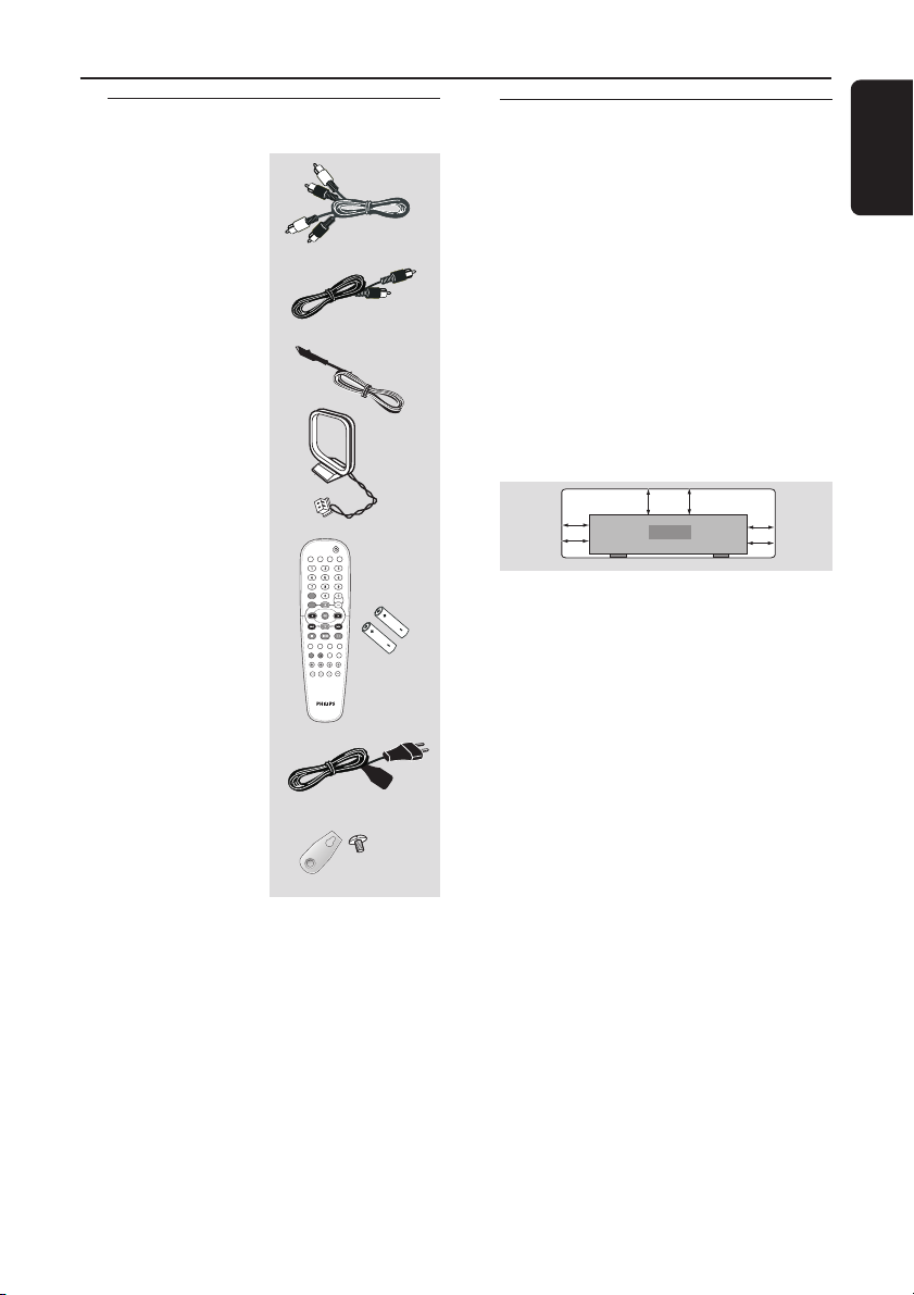
Step 1: Set up the speakers
You can choose to hang the speakers on
the wall. Attach the supplied bracket
firmly to the rear of speakers using the
supplied screws. Then mount a screw
(not supplied) on the wall where the
speaker is to be hung and hook the
speaker securely onto the mounted
screw.
CAUTION!
You should get a qualified person to
attach the brackets to the wall. DO
NOT do it by yourself to avoid
unexpected damage to the
equipment or injury to personnel.
Helpful Hints:
– The rear speakers are labelled as REAR L
(left) or REAR R (right).
– The front speakers are labelled as
FRONT L (left) or FRONT R (right).
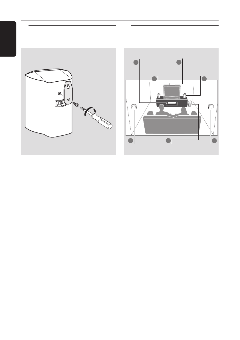
Step 2: Placing the speakers
and subwoofer
4
Subwoofer
Centre
speaker
2
Front Speaker
(Right)
1
Rear speaker
(Right)
AV Receiver
2
Front Speaker
(Left)
1
3
Rear speaker
(Left)
For best possible surround sound, all the
speakers (except subwoofer) should be
placed at the same distance from the
listening position.
1 Place the front left and right speakers at
equal distances from the TV and at an
angle of approximately 45 degrees from
the listening position.
2 Place the centre speaker above the TV or
the AV receiver so that the centre
channel’s sound is localised.
3 Place the rear speakers at normal
listening ear level facing each other or
mounted on the wall.
4 Place the subwoofer on the floor near
the TV.
Helpful Hints:
– To avoid magnetic interference, do not
position the front speakers too close to your
TV.
– Allow adequate ventilation around the AV
receiver.
3
6
Page 7
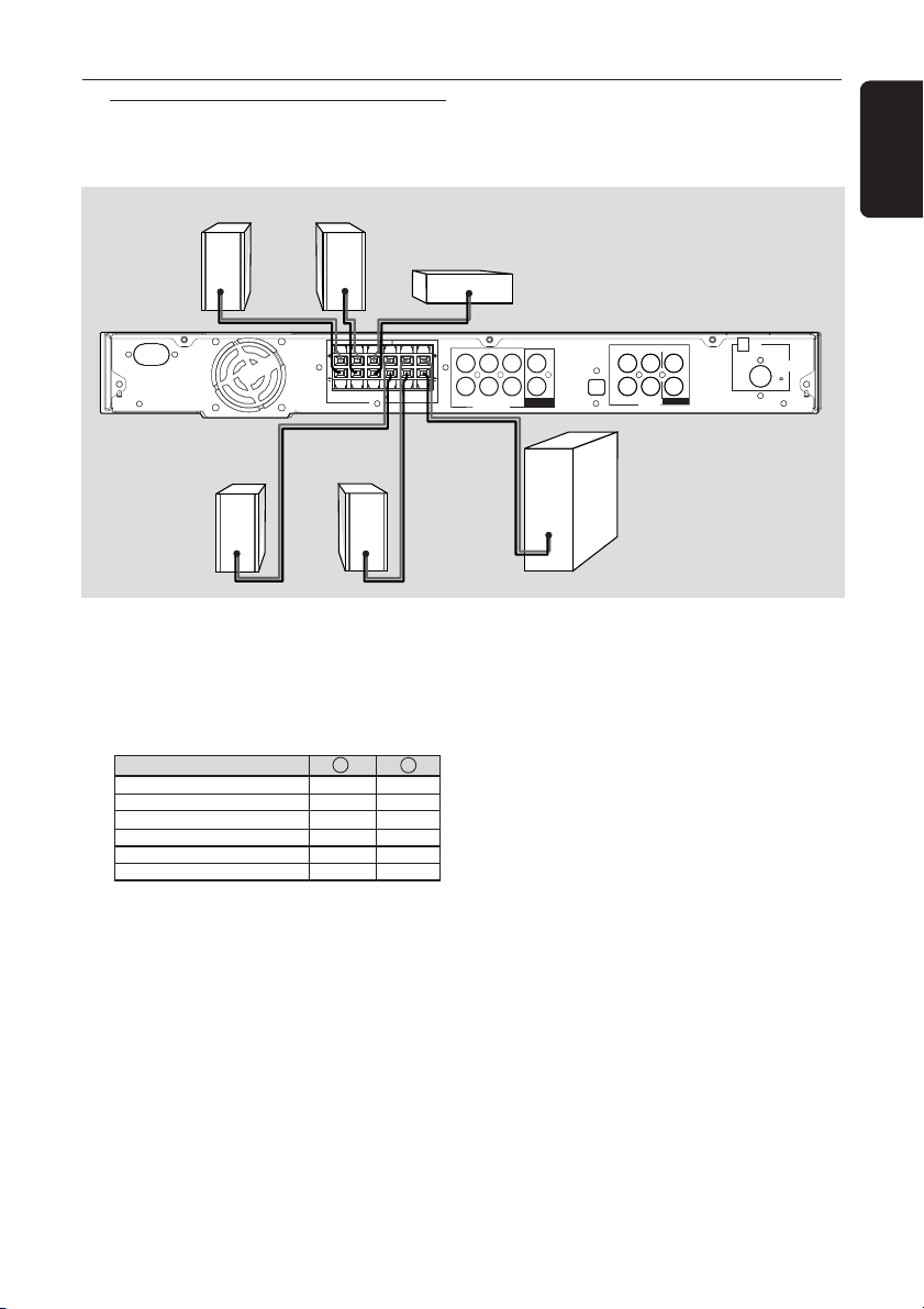
Step 3: Connecting speakers
L
SPEAKERS 3
and subwoofer
Front Right
Front Left
Connections
English
Centre
AC MAINS
SPEAKERS 3
( )
++
FRONT
REAR
REAR
FRONT
FRONT
RIGHT
SUB-
LEFT
RIGHT
LEFT
CENTER
WOOFER
Rear Right Rear Left
● Connect the supplied speaker systems by
matching the colours of the jacks and
speaker cables. Fully insert the stripped
portion of the speaker wire into the
jacks.
Speakers / Subwoofer - +
FRONT LEFT (FL) black white
FRONT RIGHT (FR) black red
FRONT CENTER (FC) black green
REAR LEFT (RL) black blue
REAR RIGHT (RR) black gray
SUBWOOFER (SUBW) black purple
Helpful Hints:
– Ensure that the speaker cables are
correctly connected. Improper connections
may damage the system due to short-circuit.
– Do not connect more than one speaker to
any one pair of +/- speaker jacks.
– Do not connect speakers with an
impedance lower than the speakers supplied.
Please refer to the SPECIFICATIONS section
of this manual.
FRONT LEFT
FRONT RIGHT
SUBWOOFER
6 CHANNEL IN
MW
ANTENNA
FM
(75 )
OPTICAL IN
L
R
AUX TV
IN OUT
AUDIO
REAR LEFTFRONT CENTER
COAXIAL IN
REAR RIGHT
COAXIAL OUT
Subwoofer
7
Page 8

L
R
L
Connections
English
Step 4: Connecting FM/MW
antennas
fix the claw into
the slot
➠
MW
antenna
1
OPTICAL IN
L
R
AUX TV
OUT
IN OUT
AUDIO
EFT
IGHT
SUBWOOFER
6 CHANNEL IN
REAR LEFTFRONT CENTER
COAXIAL IN
COAXIAL OUT
REAR RIGHT
COAXIAL OUT
1 Connect the supplied MW loop antenna
to the MW jack. Place the MW loop
antenna on a shelf or attach it to a stand
or wall.
2 Connect the supplied FM antenna to the
FM jack. Extend the FM antenna and fix
its ends to the wall.
For better FM stereo reception, connect
an external FM antenna (not supplied).
MW
FM
antenna
2
ANTENNA
FM
(75 )
Step 5: Connecting the
power cord
After everything is connected
properly, plug in the AC power cord
to the power outlet.
Never make or change any connections
with the power switched on.
Helpful Hint:
– Refer to the type plate on the rear or
bottom of the system for identification and
supply ratings.
Helpful Hints:
– Adjust the position of the antennas for
optimal reception.
– Position the antennas as far as possible
from your TV, VCR or other radiation source
to prevent unwanted interference.
8
Page 9

Optional Connections - Playback
L
AC MAINS ~
SPEAKERS 3
IMPORTANT!
– You can connect other audio and audio/visual equipments to this AV receiver
in order to use the Home Cinema Audio System’s surround sound capabilities.
– For connection to additional components, the audio/video cables are not
supplied.
– When making connections, make sure the colour of cables matches the
colour of jacks.
– Always refer to the instruction manual of the connected equipment to make
an optimal connection.
Connecting to TV/VCR/other
audio devices
English
AUDIO OUT
VCR/CD/Tape player
(for example)
AC MAINS ~
SPEAKERS 3
( )
++
FRONT
FRONT
RIGHT
REAR
FRONT
LEFT
SUB-
REAR
CENTER
LEFT
WOOFER
RIGHT
● To hear the TV channels through this AV
receiver, use the audio cables (white/red)
to connect AUDIO IN-TV jacks to the
corresponding AUDIO OUT jacks on the
TV (see fig A).
TV
DISC TUNER AUX
VOL
TV
VOL +-
Before starting operation,
1 Start playback the connected source as
usual.
2 Press TV on the remote to activate the
input source, then press VOL +- to
adjust the volume level.
L
R
B
AUDIO
OUT
S-VIDEO
IN
VIDEO IN
SCART IN
A
OPTICAL IN
TV/AV
L
R
DISC TUNER AUX
AUX TV
IN OUT
AUDIO
VOL
AUX
VOL +-
FRONT LEFT
REAR LEFTFRONT CENTER
COAXIAL IN
SUBWOOFER
6 CHANNEL IN
REAR RIGHT
COAXIAL OUT
COAXIAL OUT
FRONT RIGHT
● To hear the playback of other audio/visual
devices (such as VCR, MP3 player, cassette
player), use the audio cables (white/red)
to connect AUDIO IN-AUX jacks to the
corresponding AUDIO OUT jacks on the
connected audio device (see fig B).
Before starting operation,
1 Start playback the connected source as
usual.
2 Press AUX on the remote to activate
the input source, then press VOL +-
to adjust the volume level.
S-VIDEO
IN
AUDIO
SCART IN
OUT
VIDEO IN
MW
ANTENNA
FM
(75 )
9
Page 10

Optional Connections - Playback
English
Connecting to a DVD/SACD
player
DVD/SACD
player
You only need to make
to your DVD/SACD player from the
following options, depending on the
capabilities of your DVD/SACD player.
Option 1: Using 6 Channel In jacks
● If your DVD/SACD player has a built-in
multichannel decoder (e.g. Dolby Digital,
DTS) and has 6-channel (multichannel)
output jacks, you may use the audio
cables (not supplied) to connect the AV
receiver’s 6 CHANNEL IN jacks to the
corresponding output jacks on the
DVD/SACD player (see fig A).
one connection
OR
A B
Option 2: Using Coaxial In jack
● Or, use an coaxial cable to connect the
AV receiver’s COAXIAL IN jack to the
COAXIAL output jack on the
DVD/SACD player (see fig B).
Before starting operation,
1 Start playback the connected source as
usual.
2 Press DISC on the remote to select
“DISC COAX” in order to activate the
input source, then press VOL +- to
adjust the volume level.
OR
C
Before starting operation,
1 Start playback the connected source as
usual.
2 Press DISC on the remote to select
“DISC 6CH” in order to activate the
input source, then press VOL +- to
adjust the volume level.
Helpful Hints:
– The audio signals produced by 6 channel is
multichannel surround. Therefore, switching to
Stereo or VSS mode has no effect.
– Making recording from this input is not
possible.
10
Option 3: Using Optical In jack
● Or, use an optical fiber-optic cable (not
supplied) to connect the AV receiver’s
OPTICAL IN jack to the OPTICAL
output jack on the DVD/SACD player
(see fig C).
Before starting operation,
1 Start playback the connected source as
usual.
2 Press DISC on the remote to select
“DISC OPTI” in order to activate the
input source, then press VOL +- to
adjust the volume level.
Page 11

Optional Connections - Recording
L
A
SPEAKERS 3
Connecting to a recording
device
COAXIAL IN
/
DIGITAL IN
English
AUDIO IN
L
R
Digital Recording
device
INS ~
SPEAKERS 3
( )
++
REAR
FRONT
REAR
FRONT
FRONT
LEFT
RIGHT
SUB-
RIGHT
LEFT
CENTER
WOOFER
● Connect the AV receiver’s COAXIAL
OUT jack to the DIGITAL (COAXIAL)
IN jack on a digital recording device
(DTS-Digital Theatre System compatible,
with a Dolby Digital decoder, for
example).
➜ This will allow you to make digital or
analogue recordings from the signals
received from this AV receiver.
AND/OR
● Connect the AV receiver’s AUDIO
OUT jacks to the AUDIO IN jacks on an
analogue recording device.
➜ This will allow you to make analogue
stereo (two-channel, left and right)
recordings.
Helpful Hints:
– Dolby Digital, DTS or MPEG signal are not
possible to record from this AV receiver.
– Digital recording is not possible when the
digital source material is copy-protected.
Analogue
Recording device
OPTICAL IN
L
R
AUX TV
IN OUT
AUDIO
FRONT LEFT
FRONT RIGHT
SUBWOOFER
6 CHANNEL IN
REAR LEFTFRONT CENTER
COAXIAL IN
COAXIAL OUT
REAR RIGHT
COAXIAL OUT
Before starting recording,
1 Press DISC, TUNER, TV or AUX to
select the source you want to record
from.
➜ The name of the source appears on
the display panel.
2 Start recording on the external recording
device.
3 Start playback the connected source as
usual.
Helpful Hints:
– Recording from 6 Channel input source is
not possible.
– The sound settings will not affect the
recording.
MW
ANTENNA
FM
(75 )
11
Page 12

Functional Overview
English
Main unit and remote control
2
STANDBY-ON
1
BASS TREBLE
3
TUNING
1 STANDBY ON (B)
– Switches to standby mode or turns on
the system.
2 BASS/TREBLE
– Selects BASS (low tone) or TREBLE (high
tone) sound mode and use the VOLUME
control to change the tone level.
3 S TUNING T
– Tunes the radio frequency up/down.
4 PROG
– *Enters receiver setup menu.
– TUNER: starts automatic/manual preset
programming.
4 5 6
PROG
SOURCE
6 System display panel
7 SOUND
– Selects a sound effect.
8 PHONES
– Plug in the headphones jack. The
9 VOLUME (VOL +-)
– Adjusts the volume level.
– Selects a setting in receiver setup menu.
7 9
SOUND
8
PHONES
VOLUME
speakers output will be cancelled.
5 SOURCE
– Selects the relevant active source mode:
DISC (6CH/COAX/OPTI),
TUNER (FM/MW), AUX or TV.
(on the remote only)
– TV: switches to TV source mode.
– DISC: toggles between DISC 6CH, DISC
COAX and DISC OPTI source mode.
– TUNER: toggles between FM and MW
band.
– AUX: selects AUX mode.
* = Press and hold the button for more than five seconds.
12
Page 13

Control buttons available on the
remote only
0 1 2
– Use 1 2 to select a preset radio station.
Functional Overview
TV
5
DISC TUNER AUX
*
English
! SURROUND
– Selects multichannel surround or stereo
mode.
@ SUBW +-
– Adjusts subwoofer’s sound level.
REAR +-
– Adjusts rear speakers’ sound level.
CENTER +-
– Adjusts centre speaker’s sound level.
TV VOL +-
– Adjusts TV volume (Philips TV only).
# SLEEP
– Sets the sleep timer function.
$ DIM
– Selects different levels of brightness for
display panel.
% MUTE
– Mutes or restores the volume.
^ NIGHT (in Dolby Digital mode only)
– Optimises the dynamic of the sound
output
& Numeric Keypad (0-9)
– Enters a number of a preset radio station.
* B
– Switches to standby mode.
DISC
DVD MENU
SYSTEM
VOL
0
3
7
!
@
The following keys only operate on a
Philips DVD player. For details, please
refer to a Philips DVD player owner’s
manual
– DVD MENU - DISC
– DVD MENU - SYSTEM
– 34
– OK
– STOP
– PLAY/PAUSE
– RESUME
– REPEAT
– REPEAT A-B
PLAY/PAUSE
STOP RESUME
SURROUND SOUND NIGHT MUTE
REPEAT REPEAT SLEEP DIM
SUBW REAR CENTER TV VOL
&
9
0
3
^
%
$
#
* = Press and hold the button for more than five seconds.
13
Page 14

Getting Started
English
Step 1: Inserting batteries into
the remote control
3
1
2
1 Open the battery compartment.
2 Insert two batteries type R06 or AA,
following the indications (+-) inside
the compartment.
3 Close the cover.
Using the remote control to operate
the system
1 Aim the remote
control directly at the
remote sensor (iR) on
the front panel.
2 Select the source you
wish to control by
pressing one of the
source select buttons
on the remote control
(for example TV,
TUNER).
3 Then select the
desired function (for
example
CAUTION!
– Remove batteries if they are
exhausted or if the remote is not to
be used for a long time.
– Do not use old and new or
different types of batteries in
combination.
– Batteries contain chemical
substances, so they should be
disposed of properly.
S, T).
TV
DISC TUNER AUX
DISC
DVD MENU
SYSTEM
PLAY/PAUSE
STOP RESUME
SURROUND SOUND NIGHT MUTE
REPEAT REPEAT SLEEP DIM
Step 2: Switching on/off
After completing all the connections,
connect the AC power cord of the AV
receiver to the wall outlet.
Switching to an active mode
● Press the SOURCE control to select :
DISC 6CH ™ DISC COAX ™
DISC OPTI ™ FM ™ MW™ AUX ™
TV ™ DISC 6CH ....
OR
Press TV, DISC, TUNER or AUX on
the remote.
Switching to standby mode
● Press STANDBY ON (B).
➜ The display screen will go blank.
SOUND
Step 3: Setting the speakers
You can adjust the delay times (centre
and rear only) and volume level for
individual speakers. These adjustments let
you optimise the sound according to your
surroundings and setup.
VOL
IMPORTANT!
– Press SURROUND button on the
remote to select Multi-channel
surround mode before adjusting the
speaker settings.
– Set the ‘Test Tone’ to ‘On’ for easy
adjustment.
1 In active mode, press and hold PROG for
five seconds to enter system setup.
2 Press S / T to select one of the
following options : CENTER DELAY,
REAR DELAY, TEST TONE or MENU
OFF.
3 Press PROG to confirm.
14
Page 15

Getting Started
REPEAT REPEAT SLEEP DIM
CENTER DELAY – Select this to set
the delay time in relation to the listening
position/distance for the centre speaker :
5ms, 3ms, 2ms, 1ms or OFF (default
setting).
REAR DELAY – Select this to set the
delay time in relation to the listening
position/distance for rear speakers :
15ms, 12ms, 9ms, 6ms, 3ms or OFF
(default setting).
TEST TONE – Select this to turn ‘ON’
or ‘OFF’ (default setting) the test tone.
If you have turned on the test tone, the
test signal will be automatically generated
to help you judge the sound level of each
speaker and subwoofer.
MENU OFF – Select this to exit from
the system setup.
4 Use the VOLUME control to adjust the
settings that best suit your surround
sound needs.
➜ If the volume control is not used
within 5 seconds, it will become normal
volume control function.
5 Press PROG to confirm your selection.
Adjusting the speaker output levels
You can adjust the rear speakers, centre
speaker and subwoofer output levels by
comparing the sound from the front
speakers.
SUBW REAR CENTER TV VOL
● Press the respective buttons on the
remote (REAR +-, CENTER +-
and SUBW +-) to adjust the output
level between -15dB ~ 10dB.
Helpful Hint:
– If you have selected Stereo or VSS mode,
adjusting the centre and rear speakers’
volume level will have no effect.
English
Helpful Hints:
– Use the longer delay time settings when
the rear speakers are closer to the listener
than the front speakers.
– If “CHECK SURROUND SETTINGS”
appears on the display, press SURROUND
button to select surround mode.
– “AUTO PROG’” only available for selection
in tuner mode only.
15
Page 16

Sound Controls
English
IMPORTANT!
For proper surround sound, make
sure the speakers and subwoofer are
connected (see page 7).
Selecting surround sound
● In DISC COAX or DISC OPTI mode, if
the audio signal received is Dolby Digital
or DTS, pressing SURROUND button
will cyclic through :
DOLBY DIGITAL / DTS ™ STEREO
™ VSS (Virtual Surround Sound)
● Otherwise, pressing SURROUND
button will cyclic through :
MOVIE ™ MUSIC ™ PRO LOGIC
™ STEREO ™ VSS
Helpful Hints:
– The available Surround outputs include:
Dolby Digital, DTS (Digital Theatre Systems)
Surround, Dolby Pro Logic II and Dolby Pro
Logic.
– In VSS (Virtual Surround Sound) mode, the
surround channel is reproduced through two
front speakers.
– MOVIE and MUSIC are Dolby Pro Logic II
surround sound.
– The surround feature is not available in
DISC 6CH mode.
– The centre and rear speakers operate only
in multichannel surround mode.
– The availability of the various surround
sound modes depends on the number of
speakers used and the sound available on
the disc.
Selecting digital sound effects
Select a preset digital sound effects that
matches your disc’s content or that
optimises the sound of the musical style
you are playing.
● Press SOUND on the remote to select
the available sound effect.
In Dolby Digital, DTS, PRO LOGIC or
PRO LOGIC II (MOVIE) surround mode,
you can select :
CONCERT, DRAMA,
setting) or SCI-FI.
In VSS, PRO LOGIC II (MUSIC) surround
mode or in Tuner mode, you can select :
JAZZ, ROCK, DIGITAL (default setting)
or CLASSIC.
Helpful Hint:
– For flat sound output, select CONCERT or
CLASSIC.
ACTION (default
Adjusting the Bass/Treble
level
The BASS (low tone) and TREBLE (high
tone) features enable you to define the
sound-processor settings.
1 Press BASS or TREBLE.
2 Within two seconds, use the VOLUME
control to adjust the Bass or Treble level
(-10dB ~ 10dB, default setting - 0dB).
➜ If the volume control is not used
within two seconds, it will resume its
normal volume control function.
➜ If headphone is connected, it will
disable the bass/treble controls.
16
Page 17

NIGHT
SLEEP
MUTE
PRESET
PROGRAM
Volume Controls and Other Features
Volume control
● Adjust VOLUME control (or press
VOL +/- on the remote) to increase
or decrease the volume level.
➜ "VOL MIN" is the minimum volume
level and “VOL MAX” is the maximum
volume level.
For Philips TVs only
● Press TV VOL +/- on the remote
control to adjust the TV’s volume level.
To listen through the headphones
● Connect the headphones plug to the
PHONE socket at the front of the AV
receiver.
➜ The speakers will be mute.
➜ The current surround sound will
change to stereo mode.
To turn off the volume temporarily
● Press MUTE on the remote.
➜ Playback will continue without sound
and "
MUTE" icon appears.
➜ To restore the volume, press MUTE
again or increase the volume level.
Night Mode - turning on/off
When activated the night mode, the high
volume outputs will be softened and low
volume outputs will be brought upward
to an audible level. It is useful for
watching your favourite action movie
without disturbing others at night.
Dimming system’s display
screen
● In any active mode, press DIM on the
remote to select desired brightness :
HIGH (default setting), MID or LOW.
Setting the Sleep Timer
The sleep timer enables the system to
switch to standby mode automatically at a
preset time.
● Press SLEEP on the remote repeatedly
until it reaches the desired preset turn-off
time.
➜ The selections are as follows (time in
minutes):
15 ™ 30 ™ 45 ™ 60 ™ 90 ™ 120
™ OFF ™ 15 …
➜ “
SLEEP” icon will show on the display,
except if "OFF" is selected.
To check or change the setting
● Press SLEEP once to show the
remaining time before switching off.
If you continue pressing the SLEEP
button, the next Sleep Timer option will
appear.
To cancel the sleep timer
● Press SLEEP repeatedly until "OFF"
appears or press the STANDBY ON
button.
English
IMPORTANT!
This feature is only available for
movies with Dolby Digital mode.
● Press NIGHT on the remote repeatedly
to switch the Night mode on or off
(default setting - OFF).
Helpful Hint:
– The night mode option is not available in
DISC 6CH mode.
17
Page 18

NIGHT
SLEEP
MUTE
PRESET
PROGRAM
TUNER
Tuner Operations
English
IMPORTANT!
Make sure the FM and MW
antennas are connected.
Tuning to radio stations
Press TUNER on the remote (or press
1
SOURCE control on front panel) to
select “FM” or “MW”.
2 Press and hold S / T on the
remote until the frequency indication
starts to change, then release.
➜ "FM SEARCH" appears.
➜ The next radio station will tune
automatically.
➜
lights up for FM stereo reception.
3 To tune a weak station, press S / T
briefly and repeatedly until an optimal
reception is found.
Helpful Hint:
– If the FM radio station is transmitting RDS
(Radio Data System) signal, the RDS name
will be displayed and stored.
Presetting radio stations
You can store up to 40 preset radio
stations in the memory.
4 Press PROG again to start automatic
presetting.
➜ “SEARCH” appears.
➜ All the available radio stations with
strong transmission signal will be stored.
➜ Automatic preset will begin from
preset (1) and all your former presets will
be overridden.
Manual presetting
You can choose to store only your
favourite radio stations.
1 Tune to your desired radio station (see
“Tuning to radio stations”).
2 Press PROG.
➜ “PROGRAM” and “PRESET” icons appear.
3 Use the numeric keypad (0-9) to
select a desired preset number.
➜ If “
PROGRAM” icon goes off before you
select the desired preset number, press
PROG button again.
4 Press PROG again to store.
5 Repeat steps 1~4 to store other radio
stations.
Automatic presetting
You can store all available radio stations
automatically.
1 In tuner mode, press and hold PROG for
five seconds to enter system setup.
2 Press S / T to select “AUTO
PROG”.
AUTO PROG
3 Press PROG to confirm.
➜ “CONFIRM” appears.
18
Helpful Hints:
– If you attempt to program more than 40
preset radio stations, “PROG FULL”
appears.
– The system will exit presetting mode if no
button is pressed within two seconds.
Selecting a preset radio
station
● Press 1 2 or use the numeric keypad
(0-9) to select a preset number.
➜ The preset number follow by radio
frequency will appear.
Page 19

Troubleshooting
WARNING
Under no circumstances should you try to repair the system yourself, as this will
invalidate the warranty. Do not open the system as there is a risk of electric shock.
If a fault occurs, first check the points listed below before taking the system for repair. If
you are unable to remedy a problem by following these hints, consult your dealer or
Philips for help.
Problem Solution
English
No power.
No sound or distorted sound.
There is no sound from the centre and
rear speakers.
Radio reception is poor.
The remote control does not function
properly.
– Check if the AC power cord is properly
connected.
– Adjust the volume.
– Check the speaker connections and settings.
– Disconnect the headphones.
– Press the correct source button on the
remote (TV or AUX, for example) to choose
the equipment that you want to hear through
the AV receiver.
– Press CENTER +- or REAR +- to
adjust the volume level.
– Make sure the centre and rear speakers are
connected correctly.
– Press SURROUND button to select a correct
surround sound setting.
– Make sure the source you are playing is
recorded or broadcast in surround sound
(DTS, Dolby Digital, etc.).
– If the signal is too weak, adjust the antenna or
connect an external antenna for better
reception.
– Increase the distance between the system and
your TV or VCR.
– Tune in to the correct frequency.
– Place the antenna farther away from any
equipment that may be causing the noise.
– Select the source (DISC or TUNER, for
example) before pressing the function button
(S, T).
– Reduce the distance between the remote
control and the system.
– Replace the batteries with new ones.
– Point the remote control directly toward the
IR sensor.
– Check that the batteries are loaded correctly.
Low hum or buzz sound.
– Place the AV receiver as far away as possible
from electrical devices that may be causing
interference.
19
Page 20

Specifications
AMPLIFIER SECTION
English
Output power
- Front 100 W RMS / channel
- Rear 100 W RMS / channel
- Centre 100 W RMS
- Subwoofer 100 W RMS
Frequency Response 150 Hz – 20 kHz / –3 dB
Signal-to-Noise Ratio > 60 dB (CCIR)
Input Sensitivity
- TV In 500 mV
- AUX In 500 mV
- 6 Channel In 800 mV
TUNER SECTION
Tuning Range FM 87.5 – 108 MHz (50 kHz)
26 dB Quieting Sensitivity FM 22 dBf
Signal-to-Noise Ratio FM 55 dB
Harmonic Distortion FM Mono 3%
Frequency Response FM 180 Hz – 10 kHz / ±6 dB
Stereo Separation FM 26 dB (1 kHz)
Stereo Threshold FM 23.5 dB
MW 531 – 1602 kHz (9 kHz)
MW 5 µV/m
MW 40 dB
FM Stereo 3%
MW 5%
MAIN UNIT
Power Supply Rating 220 – 240 V; 50 Hz
Power Consumption 180 W
Dimensions (w x h x d) 435 mm x 54 mm x 388 mm
Weight 4.16 kg
SPEAKERS
Front speakers / Rear (surround) speaker
System 2-way, closed box system
Impedance 3 Ω
Speaker drivers 18mm cone dome tweeter
Frequency response 150 Hz – 20 kHz
Dimensions (w x h x d) 93 mm x 174 mm x 65 mm
Weight 0.75 kg/each
CENTRE SPEAKER
System 2-way, closed box system
Impedance 3 Ω
Speaker drivers 18mm cone dome tweeter,
Frequency response 150 Hz – 20 kHz
Dimensions (w x h x d) 245 mm x 93 mm x 65 mm
Weight 1.37 kg
PASSIVE SUBWOOFER
Frequency response 30 Hz – 150 Hz
Dimensions (w x h x d) 156 mm x 350 mm x 350 mm
Weight 4.3 kg
20
Specifications subject to change without prior
notice
Page 21

Glossary
Analogue: Sound that has not been turned
into numbers. Analogue sound varies, while
digital sound has specific numerical values.
These jacks send audio through two channels,
the left and right.
AUDIO OUT Jacks: Jacks on the back of
the AV receiver that send audio to another
system (TV, Stereo, etc.).
Digital: Sound that has been converted into
numerical values. Digital sound is available
when you use the DIGITAL AUDIO OUT
COAXIAL or OPTICAL jacks. These jacks
send audio through multiple channels, instead
of just two channels as analog does.
Dolby Digital: A surround sound system
developed by Dolby Laboratories capable of
delivering up to 5.1 discrete channels of audio
(front left and right, rear left and right, centre,
and LFE).
Dolby Pro Logic II: It creates five full-
bandwidth output channels from two-channel
sources. Decode only systems that derive 5.1
channels instead of the conventional 4
channels of Dolby Pro Logic surround sound.
Dolby Pro Logic Surround: It is a specially
encoded two-channel analogue format that will
produce sound through four speaker channels
(front left, centre, front right, mono surround)
when a Dolby Pro Logic Decoder is used. It is
also compatible with stereo systems but the
user will only have two-channel (front left &
right) of sound.
DTS: Digital Theatre Systems. This is a
surround sound system, but it is different from
Dolby Digital. The formats were developed by
different companies.
Multichannel: DVD is specified to have each
sound track constitute one sound field.
Multichannel refers to a structure of sound
tracks having three or more channels.
Super Audio CD (SACD): This audio
format is based upon the current CD
standards but includes a greater amount of
information that provides higher quality sound.
There are three types of discs: single layer,
double layer and hybrid discs. The hybrid disc
contains both standard audio CD and Super
Audio CD information.
Surround: A system for creating realistic
three-dimensional sound fields full of realism
by arranging multiple speakers around the
listener.
VSS: Virtual Surround Sound - the ProLogic
MPEG or Dolby Digital surround channel is
processed by a ‘virtualiser’ DSP to add
surround effect from just the two front
speakers.
English
21
 Loading...