

Philips LTC 3962, LTC 3924 User Manual

PHILIPS LTC3924/62 (E) QR34071
Time-lapse
Video Recorder
Instructions for Use
Eng
F
E
LTC 3924/62

1
PHILIPS LTC3924/62 (E) QR34071
1.Read Instructions — All safety and operating instructions
should be read before the unit is operated.
2. Retain Instructions — The safety and operating instructions
should be retained for future reference.
3. Heed Warnings — All warnings on the unit and in the operating
instructions should be adhered to.
4. Follow Instructions — All operating and use instructions should
be followed.
5. Cleaning — Unplug the unit from the outlet before cleaning. Do
not use liquid cleaners or aerosol cleaners. Use a damp cloth for
cleaning.
6. Attachments — Do not use attachments not recommended by the
product manufacturer as they may cause hazards.
7.Water and Moisture — Do not use this unit near water –
for example, in a wet basement, in an unprotected outdoor
installation, or any area which is classified as a wet
location.
8.Accessories — Do not place this unit on an unstable stand, tripod,
bracket, or mount. The unit may fall, causing serious injury to a
person and serious damage to the unit. Use only with a stand, tripod, bracket, or mount recommended by the manufacturer, or
sold with the product. Any mounting of the unit should follow the
manufacturer’s instructions, and should use a mounting accessory recommended by the manufacturer.
An appliance and cart combination should be
moved with care. Quick stops, excessive force, and
uneven surfaces may cause the appliance and cart
combination to overturn.
9. Ventilation — Openings in the enclosure, if any, are provided for
ventilation and to ensure reliable operation of the unit and to protect it from overheating. These openings must not be blocked or
covered. This unit should not be placed in a built-in installation
unless proper ventilation is provided or the manufacturer’s
instructions have been adhered to.
10. Power Sources — This unit should be operated only from the type
of power source indicated on the marking label. If you are not
sure of the type of power supply you plan to use, consult your
appliance dealer or local power company. For units intended to
operate from battery power, or other sources, refer to the
operating instructions.
11. Grounding or Polarization — This unit may be equipped with a
polarized alternating-current line plug (a plug having one blade
wider than the other). This plug will fit into the power outlet only
one way. This is a safety feature. If you are unable to insert the
plug fully into the outlet, try reversing the plug. If the plug should
still fail to fit, contact your electrician to replace your obsolete
outlet. Do not defeat the safety purpose of the polarized plug.
Alternately, this unit may be equipped with a 3-wire groundingtype plug, a plug having a third (grounding) pin. This plug will
only fit into a grounding-type power outlet. This is a safety feature. If you are unable to insert the plug into the outlet, contact
your electrician to replace your obsolete outlet. Do not defeat the
safety purpose of the grounding-type plug.
12. Power-Cord Protection — Power-supply cords should be routed
so that they are not likely to be walked on or pinched by items
placed upon or against them, paying particular attention to cords
and plugs, convenience receptacles, and the point where they exit
from the appliance.
13. Power Lines — An outdoor system should not be located in the
vicinity of overhead power lines or other electric light or power
circuits, or where it can fall into such power lines or circuits.
When installing an outdoor system, extreme care should be taken
to keep from touching such power lines or circuits as contact with
them might be fatal. U.S.A. models only – refer to the National
Electrical Code Article 820 regarding installation of CATV
systems.
14. Overloading — Do not overload outlets and extension cords as
this can result in a risk of fire or electric shock.
15. Object and Liquid Entry — Never push objects of any kind into
this unit through openings as they may touch dangerous voltage
points or short-out parts that could result in a fire or electric
shock. Never spill liquid of any kind on the unit.
16. Servicing — Do not attempt to service this unit yourself as opening or removing covers may expose you to dangerous voltage or
other hazards. Refer all servicing to qualified service personnel.
17. Damage Requiring Service — Unplug the unit from the outlet and
refer servicing to qualified service personnel under the following
conditions.
a. When the power-supply cord or plug is damaged.
b. If liquid has been spilled, or objects have fallen into the unit.
c. If the unit has been exposed to rain or water.
d. If the unit does not operate normally by following the operating
instructions. Adjust only those controls that are covered by the
operating instructions, as an improper adjustment of other
controls may result in damage and will often require extensive
work by a qualified technician to restore the unit to its normal
operation.
e. If the unit has been dropped or the cabinet has been damaged.
f. When the unit exhibits a distinct change in performance – this
indicates a need for service.
18. Replacement Parts — When replacement parts are required, be
sure the service technician has used replacement parts specified
by the manufacturer or that have the same characteristics as the
original part. Unauthorized substitutions may result in fire,
electric shock or other hazards.
19. Safety Check — Upon completion of any service or repairs to this
unit, ask the service technician to perform safety checks to determine that the unit is in proper operating condition.
20. Coax Grounding — If an outside cable system is connected to the
unit, be sure the cable system is grounded. U.S.A. models only –
Section 810 of the National Electrical Code, ANSI/NFPA No. 701981, provides information with respect to proper grounding of
the mount and supporting structure, grounding of the coax to a
discharge unit, size of grounding conductors, location of
discharge unit, connection to grounding electrodes, and
requirements for the grounding electrode.
21. Lightning — For added protection of this unit during a lightning
storm, or when it is left unattended and unused for long periods
of time, unplug it from the wall outlet and disconnect the cable
system. This will prevent damage to the unit due to lightning and
power-line surges.
IMPORTANT SAFEGUARDS
FCC & ICES INFORMATION
(U.S.A. and Canadian Models Only)
WARNING — This equipment has been tested and found to comply
with the limits for a Class B digital device, pursuant to Part 15 of the
FCC Rules and ICES-003 of Industry Canada. These limits are
designed to provide reasonable protection against harmful interference when the equipment is operated in a residential installation.
This equipment generates, uses and can radiate radio frequency
energy and, if not installed and used in accordance with the instructions, may cause harmful interference to radio communications.
However, there is no guarantee that interference will not occur in a
particular installation. If this equipment does cause harmful interference to radio or television reception, which can be determined by
turning the equipment off and on, the user is encouraged to try to
correct the interference by one or more of the following measures:
• Reorient or relocate the receiving antenna.
• Increase the separation between the equipment and receiver.
• Connect the equipment into an outlet on a circuit different from that
to which the receiver is connected.
• Consult the dealer or an experienced radio/TV technician for help.
Intentional or unintentional changes or modifications not expressly
approved by the party responsible for compliance shall not be made.
Any such changes or modifications could void the user’s authority to
operate the equipment.
This Class B digital apparatus meets all requirements of the Canadian
Interference-Causing Equipment Regulations.
The user may find the following booklet prepared by the Federal
Communications Commission helpful: “How to Identify and Resolve
Radio-TV Interference Problems”. This booklet is available from the
U.S. Government Printing Office, Washington, DC 20402, Stock No.
004-000-00345-4.
ENGLISH
2
PHILIPS LTC3924/62 (E) QR34071
SAFETY PRECAUTIONS
CAUTION: TO REDUCE THE RISK OF ELECTRIC SHOCK,
DO NOT OPEN COVERS. NO USER SERVICEABLE PARTS
INSIDE. REFER SERVICING TO QUALIFIED SERVICE
PERSONNEL.
This label may appear on the rear of the unit due to
space limitations.
WARNING: Electrostatic-sensitive device. Use
proper CMOS/MOSFET handling precautions to
avoid electrostatic discharge.
NOTE: Grounded wrist straps must be worn and
proper ESD safety precautions observed when
handling the electrostatic-sensitive printed circuit
boards.
The lightning flash with an arrowhead symbol, within an equilateral triangle, is intended
to alert the user to the presence of uninsulated “dangerous voltage” within the product’s enclosure that may be of sufficient
magnitude to constitute a risk of electric
shock to persons.
The exclamation point within an equilateral
triangle is intended to alert the user to presence of important operating and maintenance (servicing) instructions in the literature
accompanying the appliance.
Attention: Installation should be performed
by qualified service personnel only in accordance with the National Electrical Code or
applicable local codes.
Power Disconnect: Units with or without
ON-OFF switches have power supplied to the
unit whenever the power cord is inserted
into the power source; however, the unit is
operational only when the ON-OFF switch is
in the ON position. The power cord is the
main power disconnect for all units.
External Power Supplies
Use Only the Recommended Power Supplies.
Power supplies must comply with the
requirements of the latest version of IEC
65/VDE 0860. Substitutions may damage the
unit or cause a fire or shock hazard.
220-240 V, 50 Hz power cords, input and output, must comply with the latest versions of
IEC Publication 227 or IEC Publication 245.
220-240 V, 50 Hz Power Cords
WARNING
To prevent fire or shock hazard, do not expose
units not specifically designed for outdoor use
to rain or moisture.
1 UNPACKING
Unpack carefully. This is electronic equipment and
should be handled carefully.
Check to ensure that the following items are included:
• Model number of unit.
If an item appears to have been damaged in shipment, replace it properly in its carton and notify the
shipper. If any items are missing, notify your Philips
Communication, Security & Imaging Sales
Representative or Customer Service.
The shipping carton is the safest container in which
the unit may be transported. Save it for possible
future use.
2 SERVICE
If the unit ever needs repair service, the customer
should contact the nearest Philips Communication,
Security & Imaging Service Center for return authorization and shipping instructions.
Service Centers
U.S.A. & Canada: 800-326-3270 (717-735-6300)
Mexico & Central America: 52-5-564-2726
Europe & Middle East: 011-32-1-440-0711
South America: 54-11-4956-0837
Asia Pacific Region: 011-65-481-4422
For additional information, see www.philipscsi.com.
RISK OF ELECTRIC SHOCK
DO NOT OPEN
ATTENTION
RISQUE DE CHOC ELECTRIQUE
NE PAS OUVRIR
CAUTION
ATTENTION
OBSERVE PRECAUTIONS
FOR HANDLING
ELECTROSTATIC
SENSITIVE
DEVICES
3
PHILIPS LTC3924/62 (E) QR34071
FEATURES CONTENTS
Recording
• High Density Time-Lapse Video Recorder
• Three Touch-Selectable Recording Speeds (08, 24,
40)
• Automatic “Alarm-Command” Speed up
• Recording Check
• On-Screen and On-Tape Time/Date Information
• 7-Day Programmable On/Off Timer
• “Alarm On” Output
• Usable Audio at 08, A24 and A40 hour Speeds
Playback
• Time-of-Alarm Memory and Alarm Index Search
• High Speed Visual Search
• Four Playback Speeds (08, A24, A40, 40)
• Still Field, Field-Advance, Field-Reverse and
Reverse Playback
Security
• About 720 hours Memory Protection
• Electronic Security Lockout
IMPORTANT SAFEGUARDS .....................................1
SAFETY PRECAUTIONS............................................2
PRECAUTIONS...........................................................4
CONTROLS AND FUNCTIONS .................................5
INSTALLATION ..........................................................9
EXTERNAL CONNECTIONS....................................10
CASSETTE TAPES ...................................................11
SETUP .......................................................................12
SETTING THE TIME AND DATE..........................13
SETTING [OPTIONS] ITEMS ...............................14
SUMMER TIME FUNCTION ................................14
SETTING THE TIMER ...........................................15
SETTING THE VCR FUNCTIONS ........................17
SETTING THE BUZZER ........................................18
SETTING THE ALARM .........................................19
ALARM MEMORY RECALL AND RESET............20
OPERATION..............................................................21
TAPE RECORDING ...............................................21
REC CHECK ...........................................................21
AUTO REC CHECK ...............................................21
TIMER RECORDING .............................................21
TAPE RECYCLE.....................................................22
ALARM RECORDING ...........................................22
MASTER SYSTEM RESET ...................................22
PLAYBACK ............................................................22
SHARPNESS CONTROL ......................................22
STILL PLAYBACK .................................................23
V.LOCK ADJUST ..................................................23
PLAYBACK IN THE FIELD
ADVANCE/REVERSE MODES.........................23
VISUAL SEARCH (High Speed Scan) .................23
ALARM INDEX SEARCH ......................................23
TO SECURE THE VCR ..........................................23
PROBLEM GUIDE.....................................................24
SPECIFICATIONS .....................................................25
MAINTENANCE/INSPECTION SCHEDULES OF
MECHANICAL COMPONENTS ................................26
Note: This recorder has a rechargeable battery
to maintain display functions and recording
mode within 720 hours in the event of power
loss. When the recorder is received, the unit
must be connected to power source for 48
hours to assure the battery has been adequately charged.
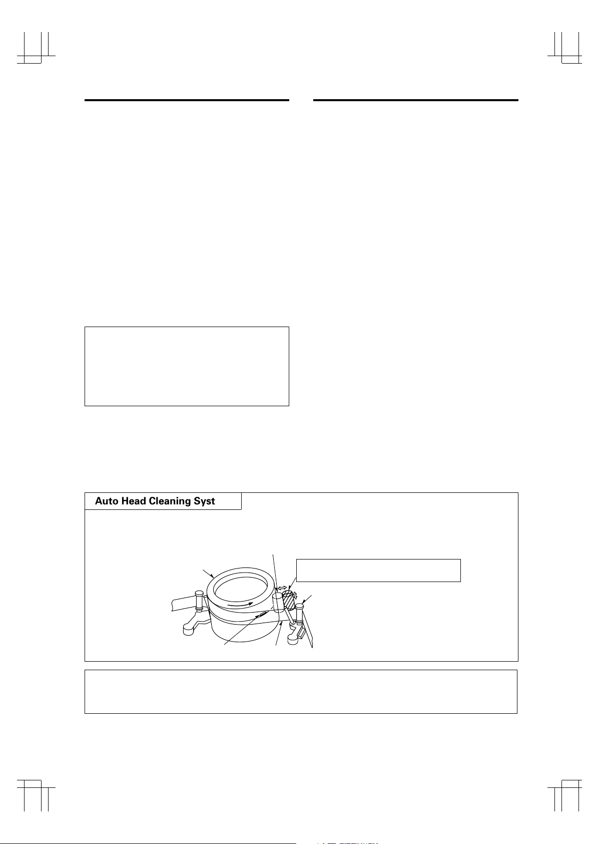
Auto Head Cleaning System
This system cleans the video heads automatically when a cassette is inserted and ejected or the tape
is rewound in the recycle recording mode, to prevent dirt from accumulating on the heads.
REC CHECK before starting
In order to prevent the misrecording, press the PLAY button during recording. See page 21.
Touches the video head in the active position
Cylinder
Video head
Tape
Cleaning roller in the stand-by position
(Special material)
Tape guide

4
PHILIPS LTC3924/62 (E) QR34071
PRECAUTIONS
Safety
• Should any solid object or liquid fall into the cabinet, turn off the unit and have it checked by qualified personnel before operating it any further.
• To disconnect the power cord, pull it out by the
plug. Never pull the cord itself.
Installation
• Choose a location in which air can pass through
the ventilation holes in the bottom, top and back
of the unit to prevent it from overheating.
• Do not install the unit near sources such as radiators or air ducts or in a place subject to direct
sunlight, excessive dust, mechanical vibrations or
shock.
• Do not place heavy objects or heat-generating
objects on the VCR, or the cabinet could be damaged or the temperature inside the VCR could rise,
which could cause a fault.
• Never bring a magnet or magnetized object near
the VCR because it will adversely affect the performance of the VCR.
• Do not install the unit in an inclined position.
The unit is designed for operation in a horizontal
position.
Operation
• Condensation
If you pour a cold liquid into a glass, water vapor
in the air will condense on the surface of glass.
This is the condensation of moisture.
Condensation on the head drum, one of the most
crucial parts of the VCR, will cause damage to the
tape.
The VCR should not be operated for at least 2
hours after being moved from a cold to a hot environment to avoid condensation from occurring
on the head drum.
Cleaning
• Be careful; when surface of the case is wiped with
a volatile agent such as benzine, alcohol, thinner,
etc., or a chemically processed cloth, the surface
finish may be degraded or its coating may peel
off.
Repacking
• It is wise to save the packing materials and box in
case you ever need to ship or store your unit.
5
PHILIPS LTC3924/62 (E) QR34071
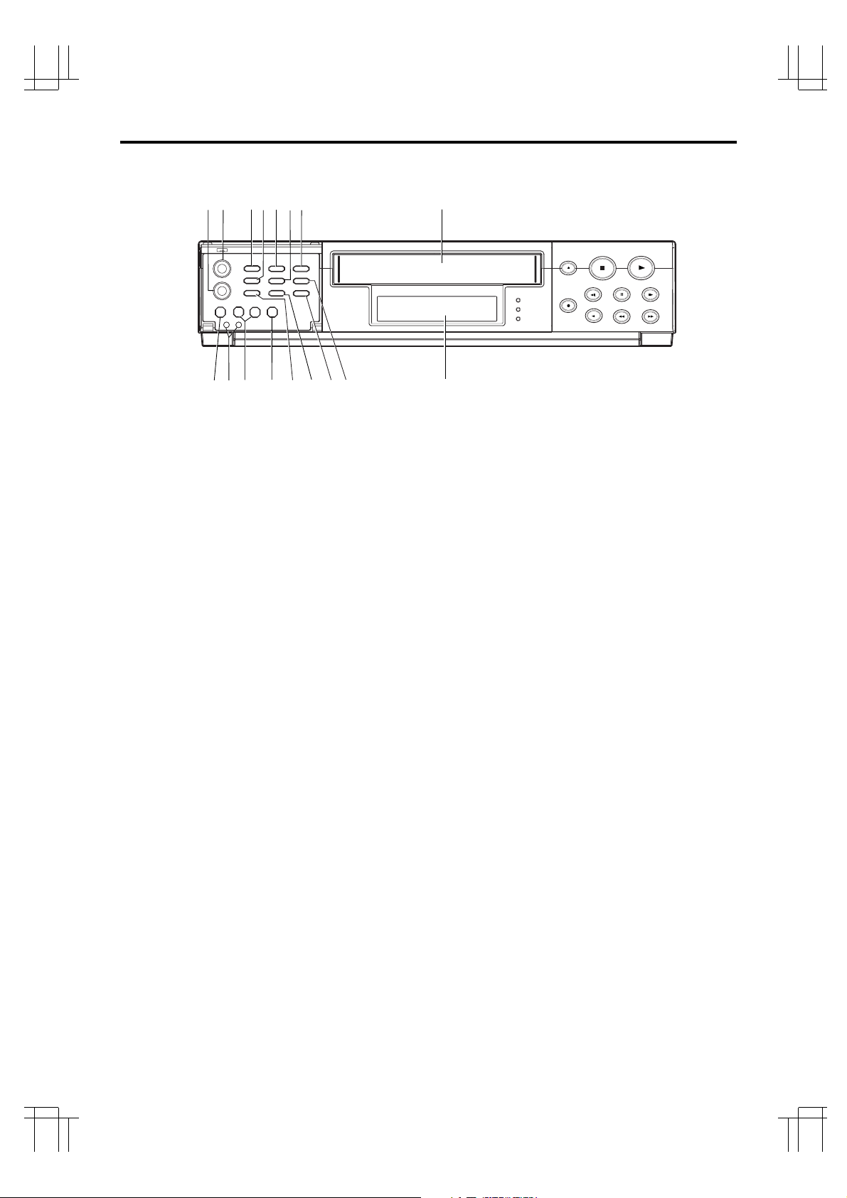
CONTROLS AND FUNCTIONS
[FRONT]
1
32
4
5
6
7
8
91011
12
13 14
15
16
DISPLAY (See page 7)
S
1. SLOW TRACKING CONTROL
Adjust to optimize the picture quality in the SLOW
PLAY mode, e.g. speed 40 hours or field advance/
reverse mode.
2. TRACKING CONTROL
Adjust to optimize the picture quality during playback
at the 08, A24 and A40 hour speeds.
3. PROG./SHARPNESS CONTROL
Press to select one of the six programmable functions.
Press to select the picture quality with the UP/HARD
or DOWN/SOFT button to hard or soft during playback. See page 22 for SHARPNESS CONTROL.
4. DOWN/SOFT BUTTON
Press to decrement, change or reverse to the
previous/lower value.
Press to adjust the picture quality to soft during playback.
5. START/STOP BUTTON
Press to start or stop the programming of a programmable function. (Press once to start the programming
sequence and a second time to stop (end) it.)
6. UP/HARD BUTTON
Press to increase, change or advance to the next
higher value.
Press to adjust the picture quality to hard during playback.
7. SET BUTTON
Press to select the specific value which is to be
changed with the UP/DOWN buttons.
8. CASSETTE COMPARTMENT
9. COUNTER RESET BUTTON
Press to clear the digital counter to “00000”.
10. RESET BUTTONS
Press these buttons at the same time to clear all
(microprocessor) functions.
Press the “S” button to reset the system. (This does
not erase the stored information.)
11. REC/PLAY HOURS BUTTONS
▲ (UP): Press to increase hours to the next
higher value.
▼ (DOWN): Press to decrease hours to the next
lower value. The tape speed will be
indicated as part of the monitor display.
12. TIMER BUTTON
Press after programming the TIMER for automatic
TIMER recording. See page 15 for TIMER programming.
13. V-POS (VERTICAL POSITION) BUTTON/V. LOCK
BUTTON
Press repeatedly to control the vertical position of the
programmable display on the monitor.
Press to reduce vertical jitter in the still play mode
14. H-POS (HORIZONTAL POSITION) BUTTON/V.
LOCK BUTTON
Press repeatedly to control the horizontal position of
the programmable display on the monitor.
Press to reduce vertical jitter in the still play mode
15. ALARM RESET BUTTON
Press to clear POWER LOSS information. When this
button is pressed the alarm memory is cleared.
16. ALARM INDEX BUTTON
Press this button to cause the INDEX indicator to light,
and set the VCR to the visual search mode (press
F.FWD or REWIND during playback mode) in this
state; the start of the alarm recorded can be located.
6
PHILIPS LTC3924/62 (E) QR34071
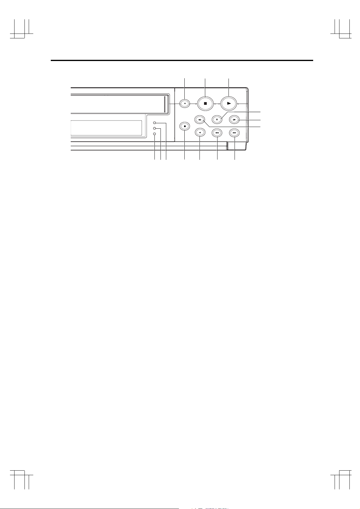
17. EJECT BUTTON
Press to remove the cassette. The EJECT button will
not operate in the RECORD mode.
18. STOP BUTTON
Press to stop the tape. The STOP button must be
pressed to end the RECORD and PLAY mode.
19. PLAY BUTTON
Press to play recorded material in the forward direction. Pressing this during recording makes it possible
to check recordings.
20.TIMER LED
The LED lights up during timer recording or timer
stand by mode.
21. ALARM LED
The LED lights up during alarm recording.
22. REC LED
The LED lights up during recording.
23. RECORD BUTTON
Press to start recording.
24. REVERSE PLAY BUTTON
Press to play recorded material at the 08 speed in the
reverse direction during the PLAY mode.
25. REWIND/VISUAL SEARCH BUTTON
Press to start rewind.
Press this button during playback and a reverse playback picture at high speed can be seen.
26. FAST FORWARD/VISUAL SEARCH BUTTON
Press to activate fast forward.
Press this button during playback and a forward playback picture at high speed can be seen.
27. FIELD REVERSE BUTTON
Press to reverse the tape by one field in the STILL
playback mode.
28. FIELD ADVANCE BUTTON
Press to advance the tape one field in the STILL playback mode.
29. STILL BUTTON
Press to momentarily stop tape motion in the play
mode. The STILL function allows close inspection of
individual scenes. See the description of STILL playback on page 23.
17
22
26
25
24
18
19
21
20
23
27
28
29
7
PHILIPS LTC3924/62 (E) QR34071
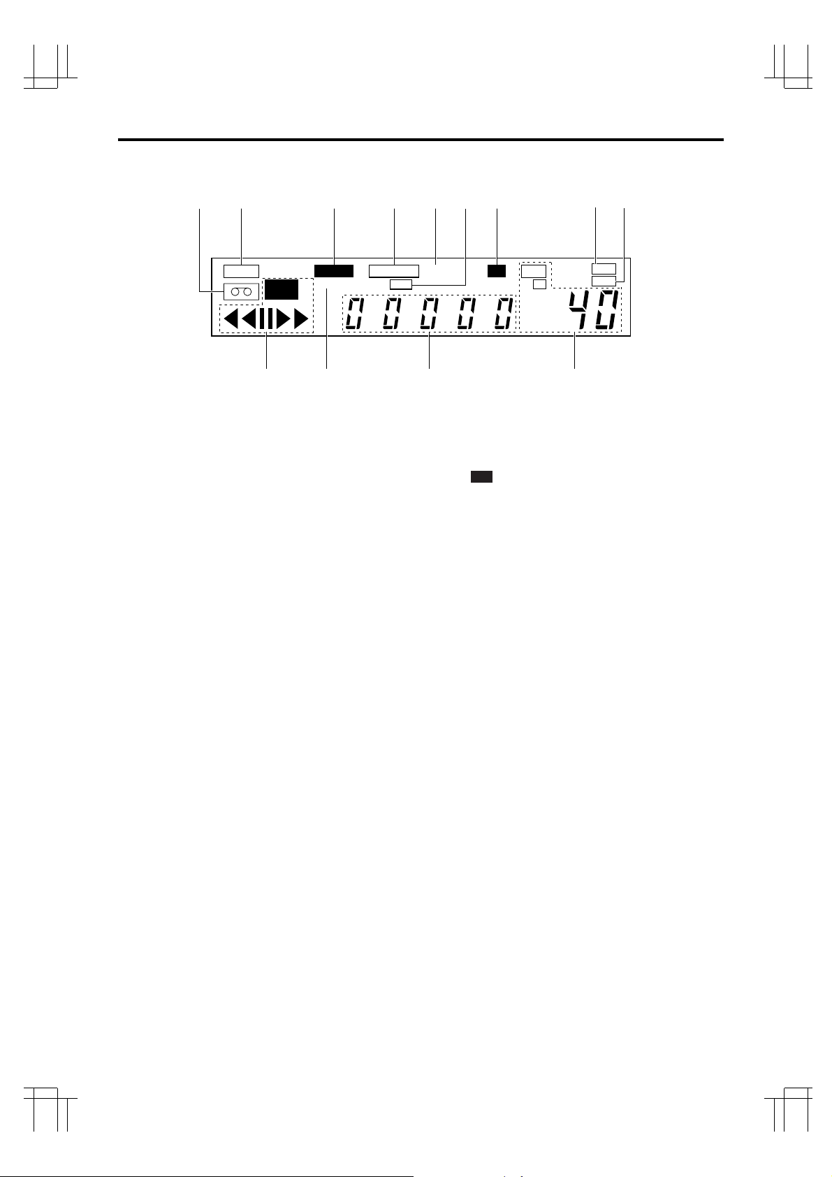
30. TAPE-IN INDICATOR
Lights when a cassette is in the compartment.
31. TAB INDICATOR
Lights when a cassette without its safety tab is loaded.
32. ALARM INDICATOR
ALARM appears during alarm recording.
ALARM flashes when alarm recording ends.
33. TAPE END INDICATOR
Lights when the tape reaches the end during recording.
Note: “TAPE END” is not displayed when you have
selected REWIND, RE-REC in the “RECYCLE FUNCTIONS” menu in the alarm display or you have selected REWIND, STOP IF ALARM but an alarm recording
has not bee made.
34. A INDICATOR
Lights when no video signal is input. Video signal
input will turn this indicator off automatically.
35. TIMER INDICATOR
This is lit during timer recording or TIMER stand-by
mode.
The indicator flashes in the following cases.
• A cassette is not loaded.
• A cassette without its safety tab is loaded.
• The timer has not been programmed.
36. LOCK INDICATOR
LOCK appears when the recorder is in the security
lock mode.
37. HARD INDICATOR
Lights when adjust the picture quality to hard during
playback mode and after setting.
38. SOFT INDICATOR
Lights when adjust the picture quality to soft during
playback mode and after setting.
39. VCR MODE INDICATORS
• appears during recording.
• tt appears during the rewind mode.
• ss appears during the fast forward mode.
• tt (or ss) flashes during visual search.
• s appears during the playback mode.
• t appears during the reverse play mode.
•
❙❙
appears when the STILL button is pressed
during play mode and disappears when the
STILL or PLAY button is pressed again.
• t
❙❙
(or ❙❙s) appears while the FIELD REV (or
FIELD ADV) is held depressed in the still
playback mode.
Note: Still playback is restored when the
FIELD REV (or FIELD ADV) button is
released.
40. INDEX INDICATOR
INDEX appears when the ALARM INDEX button is
pressed.
INDEX disappears when the ALARM INDEX button is
pressed again.
INDEX flashes during alarm indexing.
41. DIGITAL COUNTER
Shows the tape counter. The counter does not count
during non-recorded sections of a tape.
In low temperature, display speed may be slow. The
count of a counter is ensured.
42. TAPE SPEED INDICATOR
Shows the tape speed.
REC
39 41 4240
30
TAB
TAPE END
SPEED
TIMER
REC
HD
ALARM
LOCK
INDEX
31 32 33 363534
[DISPLAY]
A
HARD
SOFT
37
38
CONTROLS AND FUNCTIONS (Continued)
8
PHILIPS LTC3924/62 (E) QR34071
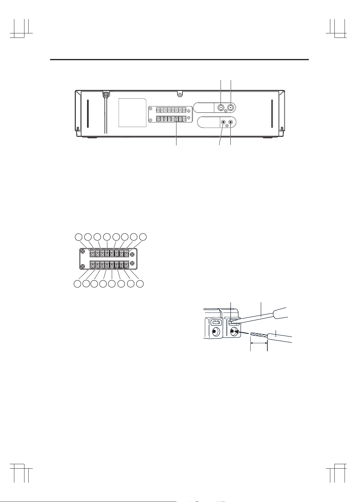
43. VIDEO IN
Receives video signal from a video camera or another
VCR.
44. VIDEO OUT
For connection to monitor.
45. EXTERNAL INTERFACE (8 X 2-PIN) JACK
Connect an alarm switch, door sensor, etc.
q ALARM IN
w ALARM OUT
e NC
r TAPE END OUT
t TAPE END RESET
y NC
u NC
i TIME ADJUST
o CAMERA SW OUT
!0 REC START IN
!1 NC
!2 NC
!3
!4 NC
!5 GND
!6 GND
[REAR]
43
44
464547
6
1
5
1
4
1
3
1
2
1
1
1
0
1
9
8
6
7
5
4
3
2
1
46. AUDIO IN
Accepts an audio signal from a camera, external
sound equipment or another recorder (Line: –8 dBm,
50 kohm, unbalanced).
47. AUDIO OUT
Provides an audio output for a monitor or another
recorder (–9 dBm, 600 ohm, unbalanced).
ScrewdriverTab
Wire
10mm
CONNECTING WIRES
1. Strip off the wire cover by approx. 10mm.
2. Use a screwdriver, etc. to hold the tab, then
insert the wire.
• Push the tab firmly when inserting wire.
3. Release the screwdriver.
• The wire will be fixed.
Note: When disconnecting the wire, use the screwdriver again to hold the tab, then pull the wire out.
 Loading...