

Page 1
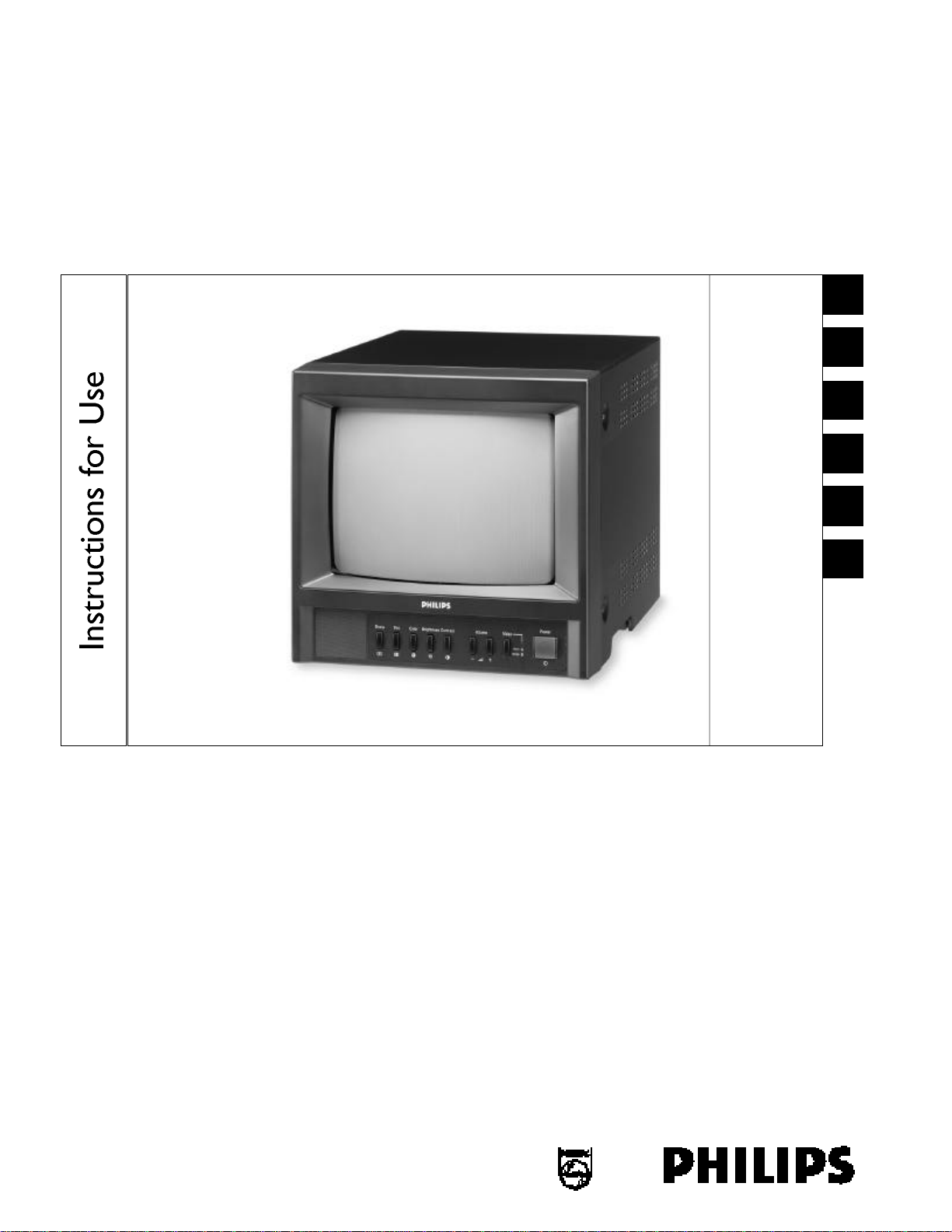
LTC 2810/90
Security Systems
Color Video Monitor
Eng
F
D
E
NL
I
Philips
Communication &
Page 2

Eng Instructions for Use.................................................................................................................................................................................1.1
F Mode d’emploi..........................................................................................................................................................................................2.1
D Bedienungsanleitung.................................................................................................................................................................................3.1
E Instrucciones de maneja.........................................................................................................................................................................4.1
NL Gebruiksaanwijzing..................................................................................................................................................................................5.1
I Istruzioni per l’uso...................................................................................................................................................................................6.1
i.2
Page 3

IMPORTANT SAFEGUARDS
1.Read Instructions - All the safety and operating instructions should be
read before the unit is operated.
2.Retain Instructions - The safety and operating instructions should be
retained for future reference.
3.Heed Warnings - All warnings on the unit and in the operating
instructions should be adhered to.
4.Follow Instructions - All operating and use instructions should be
followed.
5.Cleaning - Unplug the unit from the outlet before cleaning. Do not use
liquid cleaners or aerosol cleaners. Use a damp cloth for cleaning.
6.Attachments - Do not use attachments not recommended by the
product manufacturer as they may cause hazards.
7.Water and Moisture - Do not use this unit near water - for example,
near a bath tub, wash bowl, kitchen sink, or laundry tub, in a wet
basement, near a swimming pool, in an unprotected outdoor
installation, or any area which is classified as a wet location.
8.Accessories - Do not place this unit on an unstable stand, tripod,
bracket, or mount. The unit may fall, causing serious injury to a person
and serious damage to the unit. Use only with a stand, tripod, bracket,
or mount recommended by the manufacturer, or sold with the product.
Any mounting of the unit should follow the manufacturer’s instructions,
and should use a mounting accessory recommended by the
manufacturer.
An appliance and cart combination should be moved with
care. Quick stops, excessive force, and uneven surfaces may
cause the appliance and cart combination to overturn.
9.Ventilation - Openings in the enclosure, if any, are provided for
ventilation and to ensure reliable operation of the unit and to protect it
from overheating. These openings must not be blocked or covered.
This unit should not be placed in a built-in installation unless proper
ventilation is provided or the manufacturer’s instructions have been
adhered to.
10.Power Sources - This unit should be operated only from the type of
power source indicated on the marking label. If you are not sure of the
type of power supply you plan to use, consult your appliance dealer or
local power company. For units intended to operate from battery
power, or other sources, refer to the operating instructions.
11.Grounding or Polarization - This unit may be equipped with a polarized
alternating-current line plug (a plug having one blade wider than the
other). This plug will fit into the power outlet only one way. This is a
safety feature. If you are unable to insert the plug fully into the outlet,
try reversing the plug. If the plug should still fail to fit, contact your
electrician to replace your obsolete outlet. Do not defeat the safety
purpose of the polarized plug.
Alternately, this unit may be equipped with a 3-wire grounding-type
plug, a plug having a third (grounding) pin. This plug will only fit into a
grounding-type power outlet. This is a safety feature. If you are unable
to insert the plug into the outlet, contact your electrician to replace
your obsolete outlet. Do not defeat the safety purpose of the
grounding-type plug.
12.Power-Cord Protection - Power-supply cords should be routed so that
they are not likely to be walked on or pinched by items placed upon or
against them, paying particular attention to cords and plugs,
convenience receptacles, and the point where they exit from the
appliance.
13.Power Lines - An outdoor system should not be located in the vicinity
of overhead power lines or other electric light or power circuits, or
where it can fall into such power lines or circuits. When installing an
outdoor system, extreme care should be taken to keep from touching
such power lines or circuits as contact with them might be fatal. U.S.A.
models only - refer to the National Electrical Code Article 820
regarding installation of CATV systems.
14.Overloading - Do not overload outlets and extension cords as this can
result in a risk of fire or electric shock.
15.Object and Liquid Entry - Never push objects of any kind into this unit
through openings as they may touch dangerous voltage points or shortout parts that could result in a fire or electric shock. Never spill liquid
of any kind on the unit.
16.Servicing - Do not attempt to service this unit yourself as opening or
removing covers may expose you to dangerous voltage or other
hazards. Refer all servicing to qualified service personnel.
17.Damage Requiring Service - Unplug the unit from the outlet and refer
servicing to qualified service personnel under the following conditions:
a. When the power-supply cord or plug is damaged.
b. If liquid has been spilled, or objects have fallen into the unit.
c. If the unit has been exposed to rain or water.
d. If the unit does not operate normally by following the operating
instructions. Adjust only those controls that are covered by the
operating instructions, as an improper adjustment of other controls
may result in damage and will often require extensive work by a
qualified technician to restore the unit to its normal operation.
e. If the unit has been dropped or the cabinet has been damaged.
f. When the unit exhibits a distinct change in performance--this
indicates a need for service.
18.Replacement Parts - When replacement parts are required, be sure the
service technician has used replacement parts specified by the
manufacturer or have the same characteristics as the original part.
Unauthorized substitutions may result in fire, electric shock or other
hazards.
19.Safety Check - Upon completion of any service or repairs to this unit,
ask the service technician to perform safety checks to determine that
the unit is in proper operating condition.
20.Coax Grounding - If an outside cable system is connected to the unit,
be sure the cable system is grounded. U.S.A. models only--Section 810
of the National Electrical Code, ANSI/NFPA No.70-1981, provides
information with respect to proper grounding of the mount and
supporting structure, grounding of the coax to a discharge unit, size of
grounding conductors, location of discharge unit, connection to
grounding electrodes, and requirements for the grounding electrode.
21.Lightning - For added protection of this unit during a lightning storm, or
when it is left unattended and unused for long periods of time, unplug it
from the wall outlet and disconnect the cable system. This will prevent
damage to the unit due to lightning and power-line surges.
FCC & ICES INFORMATION
(U.S.A. and Canadian Models Only)
WARNING- This equipment has been tested and found to comply
with the limits for a Class A digital device, pursuant to Part 15 of the
FCC Rules and ICES-003 of Industry Canada. These limits are designed
to provide reasonable protection against harmful interference when the
equipment is operated in a residential installation. This equipment
generates, uses and can radiate radio frequency energy and, if not
installed and used in accordance with the instructions, may cause
harmful interference to radio communications. However, there is no
guarantee that interference will not occur in a particular installation. If
this equipment does cause harmful interference to radio or television
reception, which can be determined by turning the equipment off and
on, the user is encouraged to try to correct the interference by one or
more of the following measures:
• Reorient or relocate the receiving antenna.
• Increase the separation between the equipment and receiver.
• Connect the equipment into an outlet on a circuit different from
that to which the receiver is connected.
• Consult the dealer or an experienced radio/TV technician for help.
Intentional or unintentional changes or modifications not expressly
approved by the party responsible for compliance shall not be made.
Any such changes or modifications could void the user’s authority to
operate the equipment.
The user may find the following booklet prepared by the Federal
Communications Commission helpful: “How to Identify and Resolve
Radio-TV Interference Problems”. This booklet is available from the
U.S. Government Printing Office, Washington, DC 20402, Stock
No.004-000-00345-4.
i.3
Page 4

i.4
Page 5
SAFETY PRECAUTIONS
Attention: Installation should be performed by
qualified service personnel only in accordance with
the National Electrical Code or applicable local
codes.
CAUTION: TO REDUCE THE RISK OF
ELECTRICAL SHOCK, DO NOT OPEN
COVERS. NO USER SERVICEABLE PARTS
INSIDE. REFER SERVICING TO QUALIFIED
SERVICE PERSONNEL.
This label may appear on the bottom of the unit due to space
limitations.
The lightning flash with an arrowhead symbol,
within an equilateral triangle, is intended to alert
the user to the presence of uninsulated “dangerous
voltage” within the product’s enclosure that may
be of sufficient magnitude to constitute a risk of
electric shock to persons.
The exclamation point within an equilateral
triangle is intended to alert the user to presence of
important operating and maintenance (servicing)
instructions in the literature accompanying the
appliance.
WARNING: TO PREVENT FIRE OR SHOCK
HAZARD, DO NOT EXPOSE UNITS NOT
SPECIFICALLY DESIGNED FOR OUTDOOR
USE TO RAIN OR MOISTURE.
Power Disconnect. Units with or without ONOFF switches have power supplied to the unit
whenever the power cord is inserted into the
power source; however, the unit is operational
only when the ON-OFF switch is in the ON
position. The power cord is the main power
disconnect for all units.
COVER REMOVAL
WARNING:
REMOVAL OF THE COVER
SHOULD ONLY BE PERFORMED
BY QUALIFIED SERVICE
PERSONNEL - NOT USER
SERVICEABLE. THE UNIT
SHOULD ALWAYS BE
UNPLUGGED, BEFORE
REMOVING THE COVER AND
REMAIN UNPLUGGED WHILE
THE COVER IS REMOVED.
1.1
Page 6

CONTENTS
1 INTRODUCTION..........................................................................................................................................................1.3
1.1Unpacking..........................................................................................................................................................................1.3
1.2Monitor..............................................................................................................................................................................1.3
1.3Power..................................................................................................................................................................................1.3
2 CONTROLS AND FEATURES......................................................................................................................................1.3
2.1Front Panel........................................................................................................................................................................1.3
2.2Rear Panel..........................................................................................................................................................................1.4
3 OPERATION....................................................................................................................................................................1.5
3.1Basic Operation..................................................................................................................................................................1.5
3.2Picture adjustment..............................................................................................................................................................1.5
4 BASIC CONNECTION EXAMPLE................................................................................................................................1.5
1.2
Page 7

1 INTRODUCTION
1.1 Unpacking
Check for the following items:
• verify the model number
• power cord
• Installation Instructions
1.2 Monitor
The LTC 2810/90 is a multi-standard color monitor housed in
a metal cabinet for rugged reliability. It has a 10-inch tube
(viewable picture area 23 cm (9")). The monitor offers simple
adjustments to meet particular requirements, with default
parameters set at the factory.
With a built-in loudspeaker and inputs able to accept NSTC
and PAL standards, the monitor offers a flexible solution for a
wide variety of surveillance application.
1.3 Power
Model No. Rated Voltage Power at Sync
LTC 2810/90 100/240 VAC, 90 to 260 50 W NTSC/PAL
Voltage range (VAC)Rated V. Format
50/60 Hz
The monitor is delivered with a 2-pole Euro cord and a 3-pole
US cord.
2 CONTROLS AND FEATURES
2.1 Front Panel
1
Power switch [POWER ]
Press this switch to turn the power ON or OFF.
AUDIO A and AUDIO B terminals (RCA connector) on
the rear panel. When selected, the respective indicator
lights.
3
Volume buttons [VOLUME ]
These buttons have two functions:
Volume control: Press the + or - buttons as required to
adjust the speaker volume.
Data controls: When the SHARP, TINT, COLOR,
BRIGHTNESS and CONTRAST buttons are pressed,
used to change the value of the selected function.
4
Contrast button [CONTRAST ]
Press this button to adjust picture contrast. Adjust the value
with the VOLUMEbuttons to control the image contrast
(Default is 60).
5
Brightness button [BRIGHTNESS ]
Press this button to adjust picture brightness. Adjust the
value with the VOLUMEbuttons to control the image
brightness (Default is 50).
6
Color button [COLOR ]
Press this button to adjust the picture color intensity.
Adjust the value with the VOLUMEbuttons to control the
image color (Default is 50).
7
Tint button [TINT ] (NTSC only)
Press this button to control the picture color to be close to
nateral color. Adjust the value with the VOLUMEbuttons
to control the color tint (Default is 50).
2
Video button [VIDEO ]
Selects the composite video signal inputs to the VIDEO A
(Green LED indication) and VIDEO B (Orange LED
indication) terminal and the audio signal input to the
8
Sharp button [SHARP ]
Press this button to adjust the picture image. Adjust the
value using the VOLUMEbuttons to control the sharpness
of the image (Default is 50).
Front panel
1.3
Page 8

2.2 Rear Panel
Rear panel
9
Video A terminals [VIDEO A IN/OUT]
Video signal input (IN) and output (OUT) terminals
The output terminal is bridge-connected (auto
termination).
IN : Video signal input terminal
OUT: Bridge-connected video signal output terminal
NOTE: For corresponding audio signals, use the AUDIO A
terminals .
10
11
Video B terminals [VIDEO B IN/OUT]
Video signal input (IN) and output (OUT) terminals.
The output terminal is bridge-connected (auto
termination).
IN : Video signal input terminal
OUT: Bridge-connected video signal output terminal
NOTE: For corresponding audio signals, use the AUDIO B
terminals .
11
11
Audio A, B terminals [AUDIO A, B IN/OUT]
Audio signal input (IN) and output (OUT) terminals. The
output terminal is bridge-connected.
IN : Audio signal input terminal
OUT: Bridge-connected audio signal output terminal
NOTE: For corresponding video signals, use the VIDEO
terminals , .
12
AC Inlet
109
Power input connector. Connects the supplied AC power
cord to the appropriate AC outlet.
Note:
The impedance is automatically set to 75
Ωby the input of
a signal on the input connector while operating in a single
connection mode. However, if a cable is connected to the
output connector, the connection is placed into the open
status by the multiple connection and high impedance
automatically selected. Do not leave an unused cable
connected to the monitor. If a single cable is used, then it
must be connected to the input connector for the 75
auto termination selector to function properly.
Ω
1.4
Page 9
3 OPERATION
3.1 Basic operation
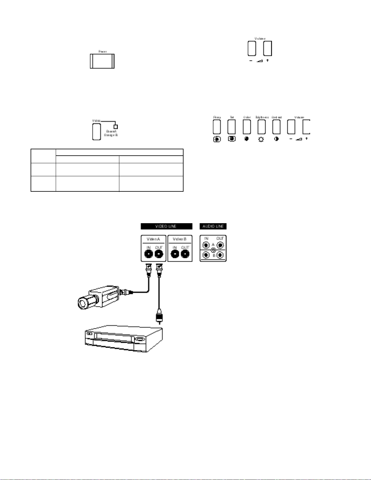
1. Press the Power switch to turn on the power.
When the power is ON, the Video Selector indicator is lit.
When the power is OFF, the Video Selector indicator is unlit.
2. Press (toggle) the Video button (A or B) to choose the input.
Button Terminals on the rear panel
Video signal input Audio signal input
A VIDEO A terminal AUDIO A terminal
(Video)
B VIDEO B terminal AUDIO B terminal
(Video)
3. Press the VOLUME button to adjust the speaker volume.
3.2 Picture Adjustment
To adjust the picture’s Sharp, Tint, Color, Brightness or
Contrast, press the appropriate button then adjust with the
Volume button. Default for each setting is 50.
4 BASIC CONNECTION EXAMPLE
The illustration below shows the basic connection of composite
video equipment.
1.5
Page 10

1.6
 Loading...