

PHILIPS L04U AA Service Manual

Colour Television Chassis
L04U
AA
E_14480_000.eps
120204
Contents Page Contents Page
1. Technical Specifications, Connections,
and Chassis Overview 2
2. Safety and Maintenance Instructions,
Warnings, and Notes 4
3. Directions for Use 6
4. Mechanical Instructions 24
5. Service Modes, Error Codes, and Faultfinding 26
6. Block Diagrams, Testpoint Overviews,
and Waveforms
Wiring Diagram 37
Block Diagram Supply and Deflection 38
Testpoint Overview Mono Carrier 39
Block Diagram Video 40
Testpoint Overview CRT & LTI Panel 41
Block Diagram Audio/Control 42
I2C and Supply Voltage Overview 43
7. Circuit Diagrams and PWB Layouts Diagram PWB
Power Supply (Diagram A1) 44 56-61
Diversity Table for A1 (Power Supply) 45 56-61
Deflection (Diagram A2) 46 56-61
Diversity Table for A2 (Deflection) 47 56-61
Tuner IF (Diagram A3) 48 56-61
Hercules (Diagram A4) 49 56-61
Features & Connectivities (Diagram A5) 50 56-61
Class D - Audio Amplifier (Diagram A6) 51 56-61
Audio Amplifier (Diagram A7) 52 56-61
Rear I/O Cinch (Diagram A8) 53 56-61
Front Control (Diagram A9) 54 56-61
DVD Power Supply (Reserved) (Diagram A10)55 56-61
CRT Panel (Diagram B1) 62 64-65
ECO Scavem Panel (Diagram B2) 63 64-65
Side AV + Headphone Panel (Diagram D) 66 67
Top Control Panel (Diagram E) 68 68
Linearity & Panorama Panel (Diagram G) 69 69
©
Copyright 2004 Philips Consumer Electronics B.V. Eindhoven, The Netherlands.
All rights reserved. No part of this publication may be reproduced, stored in a
retrieval system or transmitted, in any form or by any means, electronic,
mechanical, photocopying, or otherwise without the prior permission of Philips.
LTI/CTI Interface Panel (Diagram H) 70 71
Front Interface Panel (Diagram J) 72 72
8. Alignments 73
9. Circuit Descriptions 81
Abbreviation List 91
IC Data Sheets 92
10 Spare Parts List (not applicable) 93
11 Revision List 94
Published by BB 0462 Service PaCE Printed in the Netherlands Subject to modification EN 3122 785 14430

EN 2 L04U AA1.
Technical Specifications, Connections, and Chassis Overview
1. Technical Specifications, Connections, and Chassis Overview
Note: Described specifications are valid for the whole product
range.
Note: Figures below can deviate slightly from the actual
situation, due to different set executions.
1.1 Technical Specifications
1.1.1 Reception
Tuning system : PLL
Color systems : NTSC
Sound systems : BTSC
Channel selections : 181, full cable
IF picture carrier : 45.75 MHz
Aerial input : 75 Ohm, F-type
A/V Connections : NTSC M (3.58 - 4.5)
1.1.2 Miscellaneous
Audio output:
: 2 x 5 W
: 2 x 10 W
Power supply:
Mains voltage range : 90 - 140 V_ac
Mains frequency : 60 Hz
Ambient conditions:
Temperature range : +5 to +45 deg. C
Maximum humidity : 90 % R.H.
Power consumption:
Normal operation : from 79 W (20”)
: to 119 W (32”)
Standby : < 1 W
1.2 Connections
Note: The following connector color abbreviations are used
(acc. to DIN/IEC 757): Bk= Black, Bu= Blue, Gn= Green, Gy=
Grey, Rd= Red, Wh= White, Ye= Yellow.
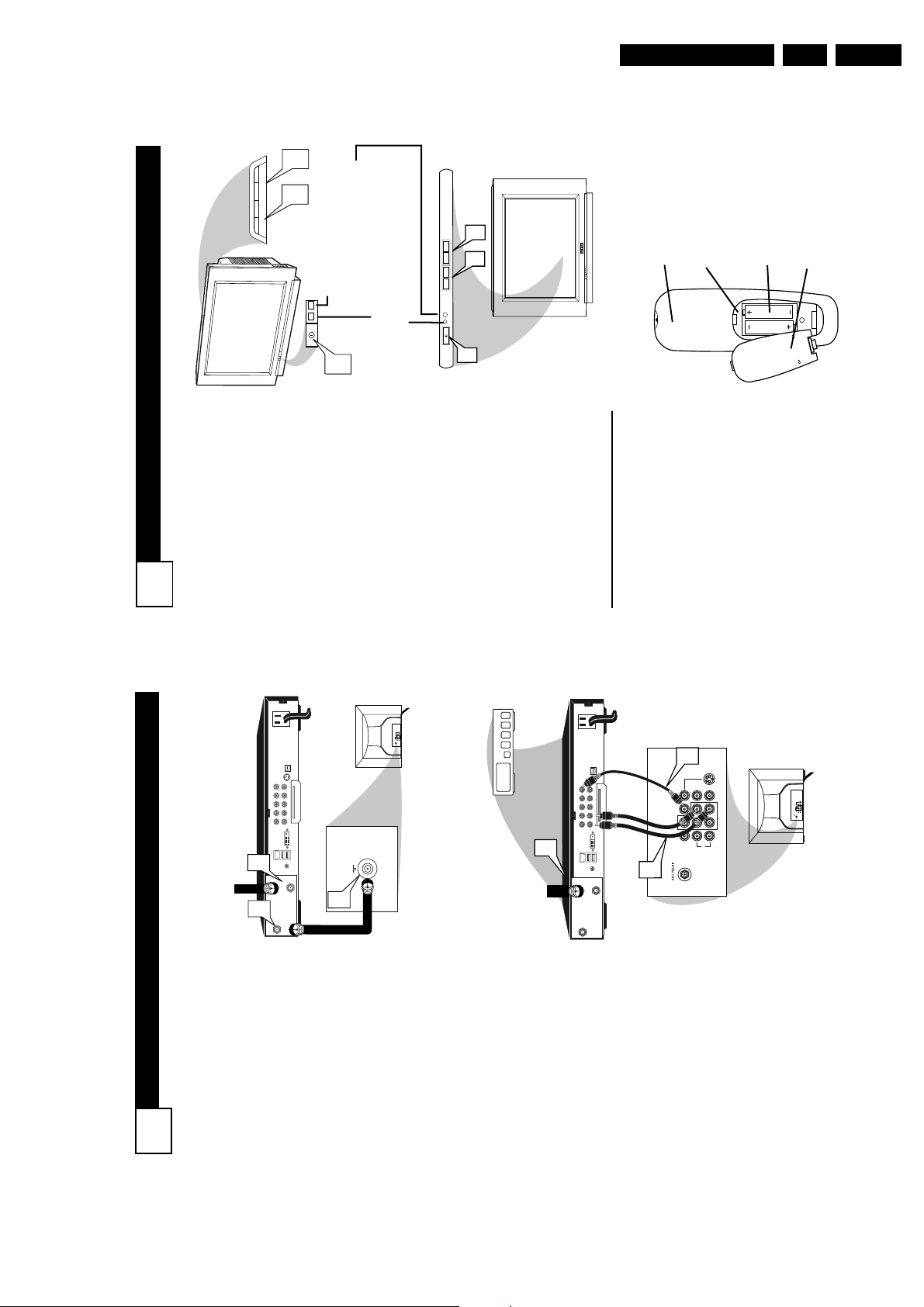
1.2.1 Top Control and Front / Side Connections
FRONT I/O
RED
IR LIGHT SENSOR
LED
TOP CONTROL
VOLUME-+-+PROGRAM
SIDE I/O
R AUDIO L VIDEO
Figure 1-1 Top control and Front / Side connections
Audio / Video In
Ye -Video (CVBS) 1 V_pp / 75 ohm H
Wh - Audio - L 0.2 V_rms / 10 kohm kq
Rd - Audio - R 0.2 V_rms / 10 kohm kq
Bk - Headphone 8 - 600 Ohm / 4 mW ot
(OPTIONAL)
P
E_14480_045.eps
170204
1.2.2 Rear Connections
75 Ohm
VIDEO
L/Mono
AUDIO
MONITOR
OUT
R
COMPONENT VIDEO INPUT
Figure 1-2 Rear connections
Aerial In
- F-type Coax, 75 ohm D
AV1
IN
Y
Pb
Pr
V
L
R
AV2
IN
V
L
R
S-VIDEO
E_14480_047.eps
110204

Technical Specifications, Connections, and Chassis Overview
Monitor Out
Ye -Video (CVBS) 1 V_pp / 75 ohm kq
Wh - Audio - L 0.5 V_rms / 1 kohm kq
Rd - Audio - R 0.5 V_rms / 1 kohm kq
YUV In
Bu -U 0.7 V_pp / 75 ohm jq
Rd - V 0.7 V_pp / 75 ohm jq
Gn - Y 0.7 V_pp / 75 ohm jq
AV1 In
Ye -Video (CVBS) 1 V_pp / 75 ohm jq
Wh - Audio - L 0.5 V_rms / 10 kohm jq
Rd - Audio - R 0.5 V_rms / 10 kohm jq
AV2 In
Ye -Video (CVBS) 1 V_pp / 75 ohm jq
Wh - Audio - L 0.5 V_rms / 10 kohm jq
Rd - Audio - R 0.5 V_rms / 10 kohm jq
AV2 In (SVHS)
1 - Ground GND H
2 - Ground GND H
3 - Y 1 V_pp / 75 ohm jq
4 - C 0.3 V_pp / 75 ohm jq
EN 3L04U AA 1.
1.3 Chassis Overview
B1
CRT
ECO
B2
SCAVEM
SIDE AV PANEL +
D
HEADPHONE
LTI/CTI INTERFACE
H
PANEL
LINEARITY &
G
PANORAMA PANEL
CRT PANEL
MONO
CARRIER
TOP CONTROL PANEL
FRONT INTERFACE PANEL
POWER SUPPLY
LINE DEFLECTION
TUNER IF
HERCULES
FEATURES & CONNECTIVITIES
CLASS D AUDIO AMPLIFIER
AUDIO AMPLIFIER
REAR I/O CINCH
FRONT CONTROL
DVD POWER SUPPLY
E_14480_046.eps
E
J
A1
A2
A3
A4
A5
A6
A7
A8
A9
A10
270204
Figure 1-3 PWB location

EN 4 L04U AA2.
Safety and Maintenance Instructions, Warnings, and Notes
2. Safety and Maintenance Instructions, Warnings, and Notes
2.1 Safety Instructions
Safety regulations require that during a repair:
• Due to the chassis concept, a very large part of the circuitry
(incl. deflection) is 'hot'. Therefore, connect the set to the
mains via an isolation transformer.
• Replace safety components, indicated by the symbol h,
only by components identical to the original ones. Any
other component substitution (other than original type) may
increase risk of fire or electrical shock hazard.
• Wear safety goggles when you replace the CRT.
Safety regulations require that after a repair, you must return
the set in its original condition. Pay, in particular, attention to
the following points:
• General repair instruction: as a strict precaution, we advise
you to re-solder the solder connections through which the
horizontal deflection current is flowing. In particular this is
valid for the:
1. Pins of the line output transformer (LOT).
2. Fly-back capacitor(s).
3. S-correction capacitor(s).
4. Line output transistor.
5. Pins of the connector with wires to the deflection coil.
6. Other components through which the deflection current
flows.
Note: This re-soldering is advised to prevent bad connections
due to metal fatigue in solder connections, and is therefore only
necessary for television sets more than two years old.
• Route the wire trees and EHT cable correctly and secure
them with the mounted cable clamps.
• Check the insulation of the mains cord for external
damage.
• Check the strain relief of the mains cord for proper function,
to prevent the cord from touching the CRT, hot
components, or heat sinks.
• Check the electrical DC resistance between the mains plug
and the secondary side (only for sets that have an isolated
power supply). Do this as follows:
1. Unplug the mains cord and connect a wire between the
two pins of the mains plug.
2. Turn on the main power switch (keep the mains cord
unplugged!).
3. Measure the resistance value between the pins of the
mains plug and the metal shielding of the tuner or the
aerial connection of the set. The reading should be
between 4.5 MΩ and 12 MΩ.
4. Switch the TV 'off' and remove the wire between the
two pins of the mains plug.
• Check the cabinet for defects, to prevent the possibility of
the customer touching any internal parts.
2.3 Warnings
• In order to prevent damage to ICs and transistors, avoid all
high voltage flashovers. In order to prevent damage to the
picture tube, use the method shown in Fig. 2-1, to
discharge the picture tube. Use a high voltage probe and a
multi-meter (position V_dc). Discharge until the meter
reading is 0 V (after approx. 30 s).
V
Figure 2-1 Discharge picture tube
• All ICs and many other semiconductors are susceptible to
electrostatic discharges (ESD, w). Careless handling
during repair can reduce life drastically. Make sure that,
during repair, you are connected with the same potential as
the mass of the set by a wristband with resistance. Keep
components and tools also at this potential. Available ESD
protection equipment:
– Complete kit ESD3 (small tablemat, wristband,
connection box, extension cable and ground cable)
4822 310 10671.
– Wristband tester 4822 344 13999.
• Together with the deflection unit and any multi-pole unit,
flat square picture tubes form an integrated unit. The
deflection and the multi-pole units are set optimally at the
factory. We do not recommend adjusting this unit during
repair.
• Be careful during measurements in the high voltage
section and on the picture tube.
• Never replace modules or other components while the unit
is 'on’.
• When you align the set, use plastic rather than metal tools.
This will prevent any short circuits and the danger of a
circuit becoming unstable.
2.4 Notes
E_06532_007.eps
110204
2.2 Maintenance Instructions
We recommend a maintenance inspection carried out by
qualified service personnel. The interval depends on the usage
conditions:
• When a customer uses the set under normal
circumstances, for example in a living room, the
recommended interval is three to five years.
• When a customer uses the set in an environment with
higher dust, grease, or moisture levels, for example in a
kitchen, the recommended interval is one year.
• The maintenance inspection includes the following actions:
1. Perform the 'general repair instruction' noted above.
2. Clean the power supply and deflection circuitry on the
chassis.
3. Clean the picture tube panel and the neck of the picture
tube.
2.4.1 General
• Measure the voltages and waveforms with regard to the
chassis (= tuner) ground (H), or hot ground (I), depending
on the tested area of circuitry.
• The voltages and waveforms shown in the diagrams are
indicative. Measure them in the Service Default Mode (see
chapter 5) with a color bar signal and stereo sound (L: 3
kHz, R: 1 kHz unless stated otherwise) and picture carrier
at 475.25 MHz for PAL, or 61.25 MHz for NTSC (channel
3).
• Where necessary, measure the waveforms and voltages
with (D) and without (E) aerial signal. Measure the
voltages in the power supply section both in normal
operation (G) and in standby (F). These values are
indicated by means of the appropriate symbols.

Safety and Maintenance Instructions, Warnings, and Notes
EN 5L04U AA 2.
• The picture tube panel has printed spark gaps. Each spark
gap is connected between an electrode of the picture tube
and the Aquadag coating.
• The semiconductors indicated in the circuit diagram and in
the parts lists, are interchangeable per position with the
semiconductors in the unit, irrespective of the type
indication on these semiconductors.
2.4.2 Schematic Notes
• All resistor values are in ohms and the value multiplier is
often used to indicate the decimal point location (e.g. 2K2
indicates 2.2 kohm).
• Resistor values with no multiplier may be indicated with
either an "E" or an "R" (e.g. 220E or 220R indicates 220
ohm).
• All capacitor values are expressed in micro-farads (µ= x
10^-6), nano-farads (n= x 10^-9), or pico-farads (p= x 10^-
12).
• Capacitor values may also use the value multiplier as the
decimal point indication (e.g. 2p2 indicates 2.2 pF).
• An "asterisk" (*) indicates component usage varies. Refer
to the diversity tables for the correct values.
• The correct component values are listed in the Electrical
Replacement Parts List. Therefore, always check this list
when there is any doubt.
2.4.3 Practical Service Precautions
• Adjust your solder tool so that a temperature around 217 220 deg. C is reached at the solder joint.
• Do not mix lead-free soldering tin with leaded soldering tin;
this will lead to unreliable solder joints!
• Use only original spare parts listed in this manual. These
are lead-free parts!
• On the website www.atyourservice.ce.philips.com you can
find more information on:
– Aspects of lead-free technology.
– BGA (de-)soldering, heating-profiles of BGAs used in
Philips sets, and others
• It makes sense to avoid exposure to electrical shock.
While some sources are expected to have a possible
dangerous impact, others of quite high potential are of
limited current and are sometimes held in less regard.
• Always respect voltages. While some may not be
dangerous in themselves, they can cause unexpected
reactions - reactions that are best avoided. Before reaching
into a powered TV set, it is best to test the high voltage
insulation. It is easy to do, and is a good service precaution.
• Before powering up the TV set with the back cover off
(or on a test fixture), attach a clip lead to the CRT DAG
ground and to a screwdriver blade that has a well insulated
handle. After the TV is powered "on" and high voltage has
developed, probe the anode lead with the blade, starting at
the case of the High Voltage Transformer (flyback - IFT).
Move the blade to within two inches of the connector of the
CRT. If there is an arc, you found it the easy way,
without getting a shock! If there is an arc to the
screwdriver blade, replace the part that is causing the
problem: the High Voltage Transformer or the lead (if it is
removable).
2.4.4 Lead Free Solder
This set is manufactured with lead-free production technology.
This is also indicated on the PWB by the PHILIPS lead-free
logo (either by a service-printing or by a sticker).
P
b
Figure 2-2 Lead-free logo
This set is produced with lead-free solder alloy as well as with
lead-free sub-parts. It can be considered as lead-free.
Due to this fact, some rules have to be respected by the
workshop during a repair:
• Use only lead-free soldering tin Philips SAC305 with order
code 0622 149 00106. If lead-free solder paste is required,
please contact the manufacturer of your soldering
equipment.
• Use only adequate solder tools applicable for lead-free
soldering tin.

EN 6 L04U AA3.
B
ASIC
A
NTENNA AND
C
ABLE
C
ONNECTIONS
Y
our home’s signal input might
come from a single (75 ohm)
round cable, a Converter Box, or from
an antenna. In either case the connec-
tion to the TV is very easy.
1
If your Cable TV signal or
Antenna signal is a round
cable (75 ohm) then you're
ready to connect to the TV.
If your antenna has flat twin-
lead wire (300 ohm), you first
need to attach the antenna wires
to the screws on a 300 to 75 ohm
adapter.
If you have a Cable Converter
Box: Connect the Cable TV sig-
nal to the Cable Signal IN(put)
plug on the Converter. 2Connect the Cable TV cable or
Antenna cable (or 300 to 75 ohm
adapter) to the 751 plug on the
TV.
If you have a Cable Converter
Box: Connect the OUT(put) plug
from the Converter to the 751
plug on the TV.
After using the AutoProgram Control,
press the CH + and – buttons to scroll
through all the channels stored in the
television’s memory.
H
ELPFUL
H
INT
75 ⍀
1
2
ANT 75‰
L/Mono
Monitor out
VIDEO
S-VIDEO
AV1 in
Y
Pb
Pr
AV2 in
AUDIO
R
COMPONENT VIDEO INPUT
Back of TV
Cable signal
coming from
Cable Company
Jack Panel
Back of TV
75 ⍀
1
2
ANT 75‰
L/Mono
Monitor out
VIDEO
S-VIDEO
AV1 in
Y
Pb
Pr
AV2 in
AUDIO
R
COMPONENT VIDEO INPUT
Antenna Connection
300 to 751
Adapter
Combination
VHF/UHF Antenna
(Outdoor or Indoor)
Twin Lead
Wire
Round Cable
751
Back of TV
Direct Cable Connection
751 Round
Coaxial Cable
1
3. Directions for Use
Directions for Use
NDEX
Subject Panel No.
Cable Box Connection . . . . . . . . . . .2
I
ANEL
P
Subject Panel No.
Active Control . . . . . . . . . . . . . . . . .23
Clock . . . . . . . . . . . . . . . . . . . . . . .18
Display Control . . . . . . . . . . . . . . .22
Specific Channel . . . . . . . . . . . . . .20
Activate Control . . . . . . . . . . . . . .21
Channel Edit . . . . . . . . . . . . . . . . . .14
Clock Controls
Start or Stop Time . . . . . . . . . . . . .19
Closed Caption Control . . . . . . . . . .31
Demo Mode . . . . . . . . . . . . . . . . . . .30
Component Video Input Jacks . . . .7
Headphone Jack . . . . . . . . . . . . . . .5
Monitor Output Jacks . . . . . . . . . . .8
S-Video Input Jacks . . . . . . . . . . . .6
AV1 Input Jacks . . . . . . . . . . . . . . .4
Antenna/Cable Basic Connection . . .1
Audio/Video Connections
Side AV Input Jacks . . . . . . . . . . . .5
AutoLock™ Controls
Factory Service Locations . . . . .36-37
Format Control . . . . . . . . . . . . . . . .17
Language Controls . . . . . . . . . . . . .11
Limited Warranty . . . . . . . . . . . . . .38
Picture Menu Controls . . . . . . . . . .15
QuadraSurf™ . . . . . . . . . . . . . . .33-34
Remote Batteries . . . . . . . . . . . . . . . .3
Remote Button Descriptions . . . .9-10
Sleeptimer . . . . . . . . . . . . . . . . . . . .31
Sound Menu Controls . . . . . . . . . . .16
Troubleshooting . . . . . . . . . . . . . . .35
Block All Channels . . . . . . . . . . . .27
Block Channels . . . . . . . . . . . . . . .26
Access Code . . . . . . . . . . . . . . . . .25
Clear All Blocked Channels . . . . .27
Movie Ratings . . . . . . . . . . . . . . . .28
Other Blocking Options . . . . . . . .30
Understanding AutoLock™ . . . . .24
TV Ratings . . . . . . . . . . . . . . . . . .29
Automatically Programming TV . .13
AutoPicture™ Control . . . . . . . . . .32
AutoSound™ Control . . . . . . . . . . .32
Tuner Mode . . . . . . . . . . . . . . . . . . .12
Basic Remote Operation . . . . . . . . . .3
Basic Television Operation . . . . . . . .3
Active Control, AutoPicture, AutoSound, and Incredible Surround are trademarks of Philips
Consumer Electronics Company. Copyright 2001 Philips Consumer Electronics.*Manufactured
under license from Dolby Laboratories. “Dolby” and the double-D symbol are trademarks of Dolby
Laboratories.
Directions for Use
POWER
3
+
–
VOLUME
+
–
CHANNEL
2
1
B
ASIC
TV
AND
R
EMOTE
C
ONTROL
O
PERATION
3
1
Press the POWER button to
turn the TV ON.
Note: You can also press any
button on the front of the TV to
turn the TV ON.2Press the VOLUME + button
to increase the sound level, or
the VOLUME – button to
lower the sound level.
Pressing both buttons at the
same time will display the on-
screen menu. Once in the
menu, use these buttons to
make adjustments or selections.
3
Press the CHANNEL UP + or
DOWN – button to select TV
channels.4Point the remote control
toward the remote sensor win-
dow on the TV when operating
the TV with the remote.
REMOTE CONTROL
T
o load the supplied batteries
into the remote:
1. Remove the battery compart-
ment lid on the back of the remote.
2. Place the batteries (2-AA) in
the remote. Be sure the (+) and (-)
ends of the batteries line up correct-
ly (inside of case is marked.)
3. Reattach the battery lid.
Battery Compartment
2-AA Batteries
Battery Lid
Back of Remote
3
2
1
Standby Light Indicator - Red light will show
when in the Standby Mode. Press the Power
button to return the TV to it’s active state.
Remote Sensor - Sensor for
activating remote control com-
mands when the remote is
used to control the TV.
Example of Models 27PT6441/37 and 27PT6442/37
Example of Models 27PT5441/37 and 32PT5441/37
TO
TV/VCR
CABLE
IN
IR
USB
DVD-D OUT
AUDIO IN
SPDIF
VIDEO
IN OUT
S-VIDEO
R L
AUDIO OUT
TV
PASSCARD
Y Pb Pr
OPTICAL
SPDIF
4
24
ANT 75‰
L/Mono
Monitor out
VIDEO
S-VIDEO
AV1 in
Y
Pb
Pr
AV2 in
AUDIO
R
COMPONENT VIDEO INPUT
L/Mono
Monitor out
VIDEO
S-VIDEO
AV1 in
Y
Pb
Pr
AV2 in
AUDIO
R
COMPONENT VIDEO INPUT
5
6
C
ABLE
B
OX
C
ONNECTIONS
2
I
f your cable signal uses a cable
box or decoder, follow the easy
steps below to complete the connec-
tion.
Cable Box (w/RF In/Outputs):
This connection will be mono.
1
Connect the Cable Company
supplied cable to
the signal
IN(put) plug on the back of the
Cable Box.
2
Using a separate round coaxial
cable, connect one end to the
OUT(put)
(TO TV) plug on the
back of the Cable Box.
3
Connect the other end of the
round coaxial cable to the 751
input on the back of the televi-
sion. Screw it down finger tight.
NOTE: If applicable, set the OUT-
PUT CHANNEL SWITCH on the
back of the cable box to CH 3 or 4.
Tune the TV to the same channel and
change channels at the cable box. In
some cases, the cable box will auto-
matically tune to either channel 3 or 4,
change channels until the picture
appears.
Cable Box (w/Audio/Video
Outputs):
This connection will supply Stereo
sound.
4
Connect the Cable Company
supplied cable to
the cable sig-
nal IN(put) plug on the back of
the Cable Box.
5
Using a RCA type Video Cable,
connect one end of the cable to
the Video (or ANT , your cable
box may be labeled differently)
Out jack on the cable box and
the other end to the AV1 Video
Input on the TV.6Connect one end of the Audio
Left and Right Cable to the left
and right Audio Out L& R
jacks on the cable box. Connect
the other end to the AV1 Audio L
& R Input jacks on the TV.
NOTE: Use the AV button on the TV
remote control to tune to the AV1
channel for the cable box signal. Once
tuned, change channels at the cable
box, not the television.
Jack Panel Back of Cable Box
Cable Signal IN from the
Cable Company
Round 751
Coaxial Cable
Jack Panel Back of TV
Cable Signal IN
from the Cable
Company
Cable Box with A/V Outputs
Jack Panel Back of TV
Audio Cables
L (White) & R (Red)
Video Cable
(Yellow)
Cable Box (w/RF In/Outputs):
Cable Box (w/Audio/Video Outputs):
EN 7L04U AA 3.
SPDIF
OPTICAL
S-VIDEO
VIDEO
IN OUT
Y Pb Pr
SPDIF
AUDIO IN
AUDIO OUT
R L
TV
PASSCARD
DVD-D OUT
USB
IR
1
IN
CABLE
2
TO
TV/VCR
75 ⍀
3
S-VIDEO
AV2 in
Y
Pr
Pb
AV1 in
COMPONENT VIDEO INPUT
Monitor out
R
AUDIO
VIDEO
L/Mono
ANT 75‰
EN 8 L04U AA3.
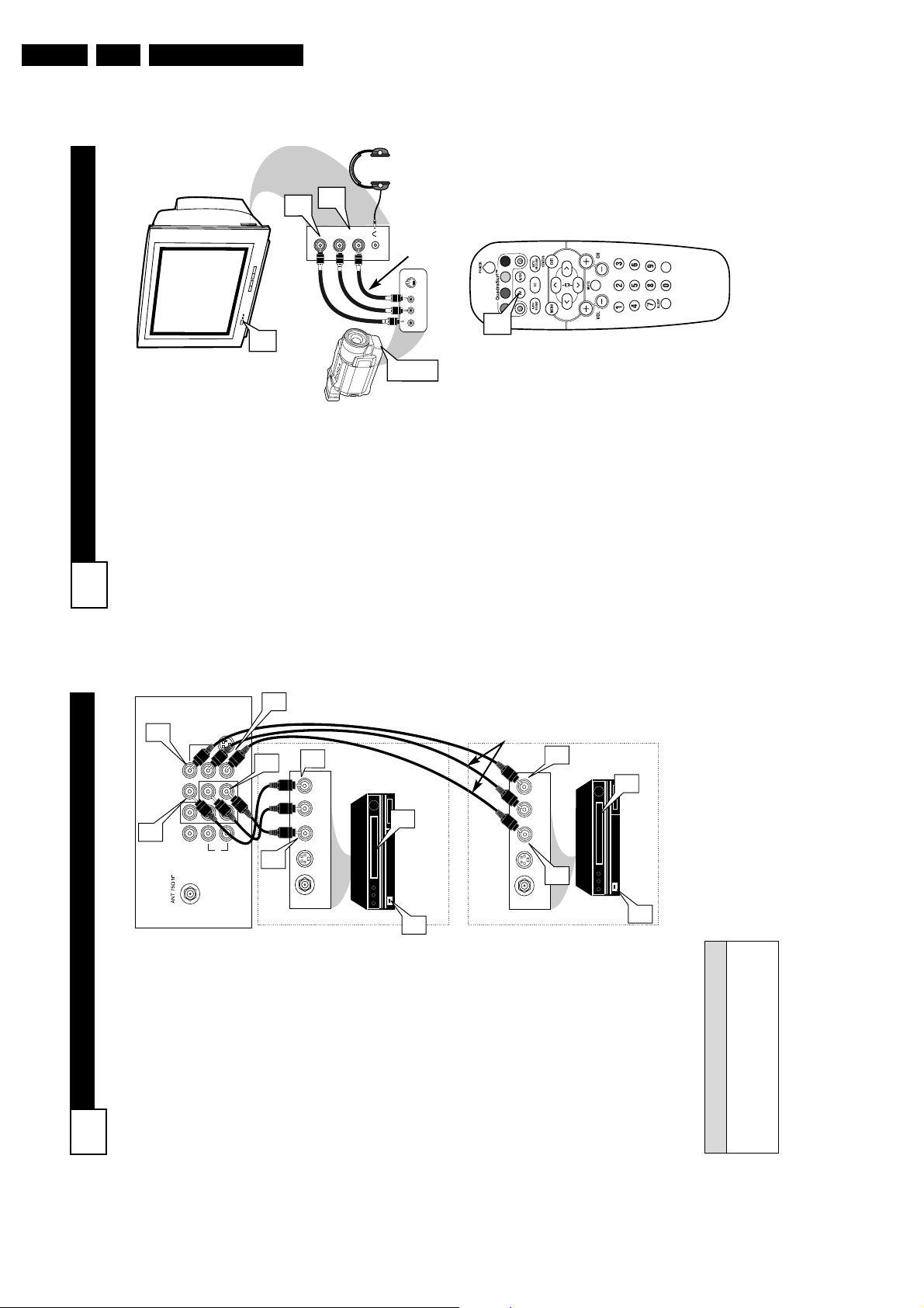
S
IDE
AV C
ONNECTIONS
5
A
udio and Video Side Inputs are
available for a quick connec-
tion of a VCR, to playback video
from a camera, or attach a gam-
ing device. Use the AV button on
the remote control to tune these
inputs.
1
Connect the video (yellow)
cable from the Video output
on the Camera (or accessory
device) to the Video (yellow)
Input located on the SIDE of
the TV.2For Stereo Devices: Connect
the audio cable (red and
white) from the Audio Left
and Right Outputs on the
Camera to the Audio In
(white) jack on the SIDE of
the television.
For Mono Devices: Connect
one end of the audio cable
from the Audio Out jack on
the device to the Audio In
(white) jack on the SIDE of
the television.
3
Turn the TV and the accesso-
ry device ON.
4
Press the AV button on the
remote control to tune the TV
to the side input jacks.
“Front” will appear on the
TV screen.5Press the PLAY 䊳 button
on the accessory device to
view playback, or to access
the accessory device (camera,
gaming unit, etc.).
VIDEO
AUDIO
L
R
Front
S-VIDEO
VIDEOAUDIO
LEFT RIGHT
3
1
2
3
5
VOL
4
Side Jack panel
of TV
Audio
Cables
Video
Cable
Jack Panel of Accessory Device
Optional
Headphones
AV (A
UDIO
/V
IDEO
) I
NPUT
C
ONNECTION
4
Audio and video cables are not sup-
plied with the TV, but are available
from Philips or electronics retailers.
H
ELPFUL
H
INT
Audio In
(Red and
White)
VCR Two (or accessory
device) (Equipped with
Video and Audio Output Jacks)
Video In
(Yellow)
Back of VCR
Back of TV
AV1
Connection
AV2 Connection
VCR One (or
accessory device) (Equipped
with Audio and Video Output
Jacks)
T
he TV’s audio/video input jacks
are for direct picture and sound
connections between the TV and a
VCR (or similar device) that has
audio/video output jacks. Both the
AV1 and AV2 Input Jack connections
are shown on this page, but either
one can be connected alone. Follow
the easy steps below to connect your
accessory device to the AV1and AV2
IN Jacks located on the back of the
TV.
1
Connect the VIDEO (yellow)
cable to the VIDEO AV1 IN (or
AV2 IN) jack on the back of the
TV.
2
Connect the AUDIO (red and
white) cables to the AUDIO (left
and right) AV1 IN (or A V2 in)
jacks on the rear of the TV.
3
Connect the VIDEO (yellow)
cable to the VIDEO OUT jack on
the back of the VCR (either one
or two) or accessory device being
used.4Connect the AUDIO (red and
white) cables to the AUDIO (left
and right) OUT jacks on the rear
of the VCR (either one or two) or
accessory device being used.
5
Turn the VCR (either one or
two) or accessory device and
the TV ON.
6
Press the AV button to set the
TV to its AV1or AV2 channel.
7
With either of the VCRs (or
accessory devices) ON and a pre-
recorded tape (CD, DVD, etc.)
inserted, press the PLAY button
to view the tape on the television.
Directions for Use
1
3
AV2 in
AV1 in
Monitor out
VIDEO
Y
L/Mono
S-VIDEO
Pr
Pb
COMPONENT VIDEO INPUT
R
AUDIO
2
4
2
OUT
VIDEO
AUDIO OUT
R L
OUT
S-VIDEO
OUT
ANT/CABLE
3
4
7
5
1
OUT
VIDEO
AUDIO OUT
R L
OUT
S-VIDEO
OUT
ANT/CABLE
7
5
Directions for Use
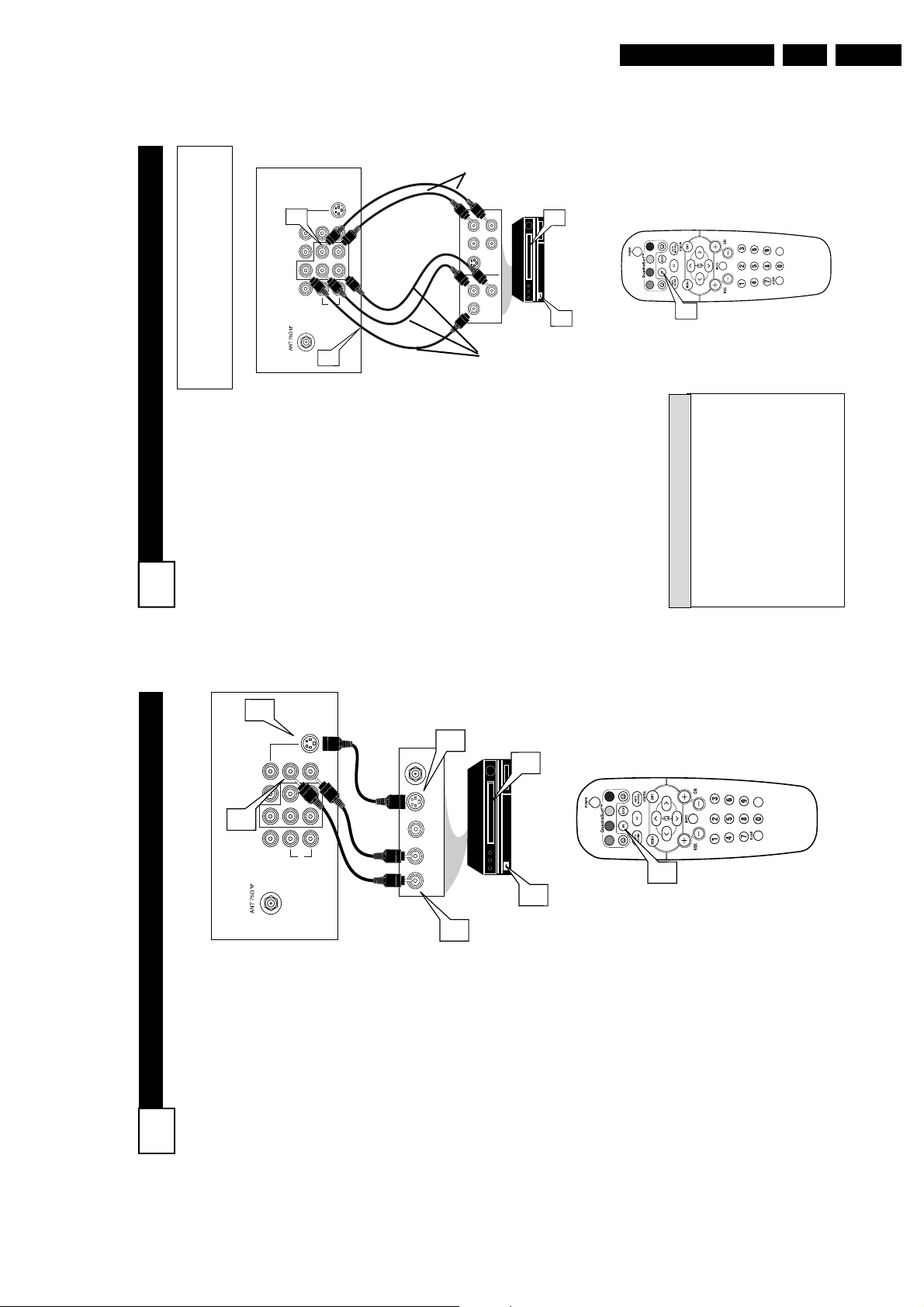
C
OMPONENT
V
IDEO
(CVI) I
NPUT
C
ONNECTIONS
C
omponent Video inputs provide
for the highest possible color
and picture resolution in the play-
back of digital signal source materi-
al, such as with DVD players. The
color difference signals (Pb, Pr) and
the luminance (Y) signal are con-
nected and received separately,
which allows for improved color
bandwidth information (not possible
when using composite video or S-
Video connections).
1
Connect the Component (Y,
Pb, Pr) Video OUTjacks from
the DVD player (or similar
device) to the (Y, Pb, Pr) in(put)
jack on the TV. When using the
Component Video Inputs, it is
best not to connect a signal to the
AV in Video Jack. 2Connect the red and white
AUDIO CABLES to the Audio
(left and right) output jacks on
the rear of the accessory device
to the Audio (L and R) AV1 in
Input Jacks on the TV.3Turn the TV and the DVD (or
digital accessory device) ON.
4
Press the AV button or the
CH + or CH – buttons to
scroll the available channels
until CVI appears in the upper
left corner of the TV screen.5Insert a DVD disc into the
DVD player and press the
PLAY 䊳 button on the DVD
Player.
The description for the component video
connectors may differ depending on the
DVD player or accessory digital source
equipment used (for example, Y, Pb, Pr; Y,
B-Y, R-Y; Y, Cr, Cb). Although abbrevia-
tions and terms may vary, the letters b and r
stand for the blue and red color component
signal connectors, and Y indicates the lumi-
nance signal. Refer to your DVD or digital
accessory owner’s manual for definitions and
connection details.
H
ELPFUL
H
INT
VOL
L/Mono
Monitor out
VIDEO
S-VIDEO
AV1 in
Y
Pb
Pr
AV2 in
AUDIO
R
COMPONENT VIDEO INPUT
S-VIDEO
OUT
OUT
OUT
L
R
AUDIO
VIDEO
COMP VIDEO
Y
Pb
Pr
2
1
3
5
4
Component
Video Cables
(Green, Blue,
Red)
Audio
Cables
(Red &
White)
Accessory Device
Equipped with
Component Video
Outputs
Back of TV
The CVI connection will be dominate over the AV1
in Video Input. When a Component Video Device is
connected as described, it is best not to have a video
signal connected to the AV1 in Video Input jack.
7
S-V
IDEO
(S-V
HS
) I
NPUT
C
ONNECTIONS
T
he S(uper)-Video connection on
the rear of the TV can provide
you with better picture detail and
clarity for the playback of accessory
sources such as DBS (digital broad-
cast satellite), DVD (digital video
discs), video games, and S-VHS VCR
(video cassette recorder) tapes than
the normal antenna picture connec-
tions.
NOTE: The accessory device must
have an S-VIDEO OUT(put) jack in
order for you to complete the connec-
tion on this page.
1
Connect one end of the S-
VIDEO CABLE to the S-
VIDEO jack on the back of the
TV. Then connect one end the
AUDIO (red and white)
CABLES to the AV1 in AUDIO
L and R (left and right) jacks on
the rear of the TV.
2
Connect other end of the S-
VIDEO CABLE to the S-VHS
(S-Video)OUT jack on the back
of the VCR. Then connect the
other ends of the AUDIO (red
and white) CABLES to the
AUDIO (left and right) OUT
jacks on the rear of the VCR.3Turn the VCR and the TV
ON.4Press the AV button or the
CH + or CH – buttons on the
remote to scroll the channels
until SVHS appears in the upper
left corner of the TV screen.5Now your ready to place a pre-
recorded video tape in the VCR
and press the PLAY 䊳 button
.
VCR or External
Accessory Device
(with S-Video
Output)
Audio Cables
(Red &
White)
S-Video
Cable
Back of TV
6
EN 9L04U AA 3.
1
S-VIDEO
1
AV2 in
Y
Pr
Pb
AV1 in
2
Monitor out
VIDEO
L/Mono
AUDIO
R
COMPONENT VIDEO INPUT
OUT
ANT/CABLE
OUT
S-VIDEO
OUT
VIDEO
AUDIO OUT
L R
2
5
VOL
4
3
EN 10 L04U AA3.
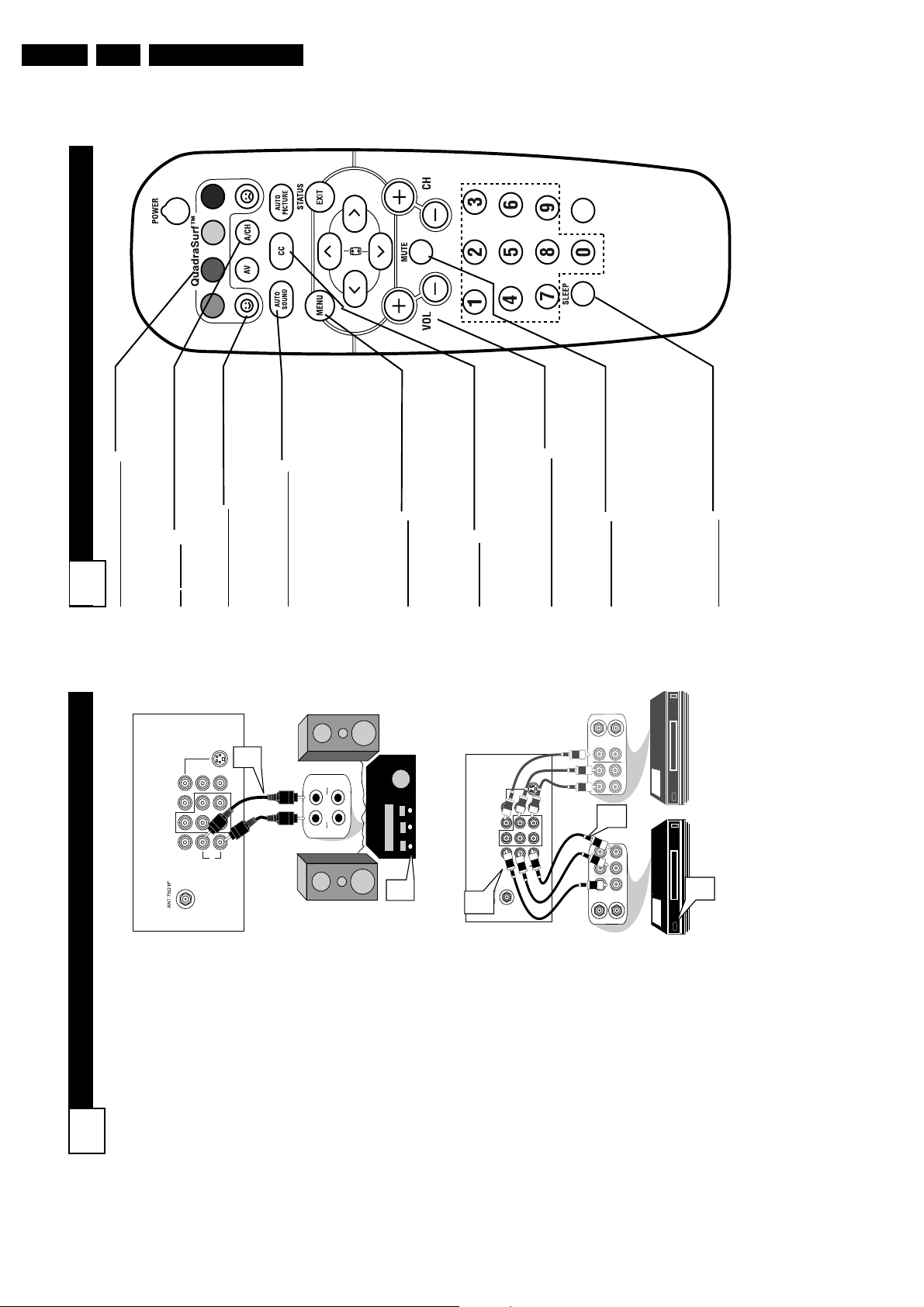
R
EMOTE
C
ONTROL
B
UTTON
D
ESCRIPTIONS
9
QUADRASURF Buttons
(Red, Green, Yellow, Blue) Allows you to
store and surf up to 10 channels you
choose for each colored button.
A
V Button
Press to select an accessory signal input
from the front AV Inputs.
SMILEY
Button
Press to add channels to the
“QuadraSurf” lists. Works with all col-
ored buttons.
AUT
O SOUND Button
Press repeatedly to choose from different
factory pre-defined sound settings.
Choose from Personal (how you set the
Sound Menu options), Voice (for pro-
gramming with speaking only), Music
(for musical type programs such as con-
certs), or Theatre (used when watching
movies).
MENU
Button
Press to display the on-screen menu. Also
can be used to back out of the on-screen
menu until it disappears from the TV’s
screen.
CC Button
Press to activate the Closed Captioning
options. Repeatedly pressing the CC but-
ton will scroll the available options on the
TV screen.
V
OL(ume) + or - Buttons
Press the VOL + button to increase the
TV’s sound level. Press the VOL– button
to decrease the TV’s sound level.
MUTE Button
Press the mute button to eliminate the
sound being heard from the TV. “MUTE”
will be displayed on the TV’s screen.
Press again to restore the TV’s volume to
it’s previous level. pressing this button for
3-4 seconds will activate the Demo Mode.
(See panel 30 for more details.)
SLEEP
Button
Press the Sleep button to set the TV to
automatically turn itself off after a set
period of time. Press repeatedly to select
15, 30, 45, 60, 90, 120, 180, or 240 min-
utes.
VOL
M
ONITOR
O
UT
(
PUT
) C
ONNECTIONS
8
T
he Audio/Video (Monitor) Output
jacks are great for recording with
a VCR or used to connect an exter-
nal audio system for better sound
reproduction.
AUDIO SYSTEM
CONNECTION:
1
Connect one end of the
R(ight) and L(eft) AUDIO
(Monitor Out) jacks on the TV
to the R and L audio input jacks
on your amplifier or sound sys-
tem. Set the audio system’s vol-
ume to a normal listening level.
2
Turn the TV and audio sys-
tem ON. To adjust the volume
on the audio system, you will
need to change the volume at
the external audio system, not
the television.
SECOND VCR CONNECTION:
NOTE: Refer to panel number 4 for
the proper hookup of the first VCR.
Follow the instructions on how to
tune to the AV1 channel to view a
pre-recorded tape.
The following steps allow you to
connect a second VCR to record
the program while your watching
it.
3
Connect one end of the yellow
Video Cable to the Monitor
Out VIDEO plug. Connect the
other end to the VIDEO IN plug
on the second VCR.4Connect one end of the red
and white Audio cable from
the Monitor Out AUDIO Land
R plugs on the TV to the
AUDIO IN plugs on the VCR.5Turn the Second VCR ON,
insert a VHS tape and it’s
ready to record what’s being
viewed on the TV screen.
Back of TV
Audio Cables
(Red and White)
Back of TV
Audio
Cables
1st VCR
(refer to panel 4 for
proper connection)
Video
Cable
2nd VCR with Audio and
Video Input Jacks
SECOND VCR CONNECTION:
AUDIO SYSTEM CONNECTION:
Directions for Use
S-VIDEO
1
AV2 in
Y
Pr
Pb
AV1 in
AUDIO
L/Mono
COMPONENT VIDEO INPUT
R
Monitor out
VIDEO
L
R
T
U
UT
P
P
IN
V
O IN
/T
N
X
O
U
H
A
P
2
IN
OUT
ANTENNA
ANTENNA
OUTOUT
VIDEO
S-VIDEO
AV2 in
Y
Pr
Pb
AV1 in
Monitor out
COMPONENT VIDEO INPUT
R
AUDIO
VIDEO
L/Mono
3
LR
AUDIO
4
RL
AUDIO
OUT OUT
VIDEO
IN
OUT
ANTENNA
ANTENNA
IN
IN
IN
IN
5
Directions for Use
VOL
Main
Picture
Sound
Features
Install
Brightness
Color
Picture
Sharpness
Tint
More...
Main
Picture
Sound
Features
Install
Language
Tuner Mode
Auto Program
Channel Edit
Install
Language
Tuner Mode
Auto Program
Channel Edit
English
OR
Instalar
Idioma
Sinton a
Auto Programa
Editar Canal
Espa ol
6
2
4
3
5
1
2
4
Installation
Langue
Mode synt.
Progr. auto.
diter progr.
Fran ais
OR
F
or French and Spanish speaking
TV owners an onscreen
Language option is present. With the
Language control you can set the
TV’s on-screen menu to be shown in
English, French, or Spanish.
1
Press the MENU button on
the remote control to show the
on-screen menu.
2
Press the CURSOR UP 3 or
DOWN 4 buttons to scroll
though the on-screen menu
until the word Install is high-
lighted.3Press the CURSOR RIGHT
2 button to display the
Install menu features.
4
Press the CURSOR UP 3 or
DOWN 4 buttons to scroll
through the Install features until
the word Language is high-
lighted.5Press the CURSOR RIGHT
2 button repeatedly to
select English, Francais
(French), or Español
(Spanish).
6
When finished, press the
STATUS/EXIT button to
remove the menu from the
TV’s screen.
H
OW TO
U
SE THE
L
ANGUAGE
C
ONTROL
11
The Language control only
makes the TV’s on-screen Menu
items appear in English, Spanish,
or French text.
It does not change the other on-
screen text features such as
Closed Caption (CC) TV shows.
H
ELPFUL
H
INT
R
EMOTE
C
ONTROL
B
UTTON
D
ESCRIPTIONS
10
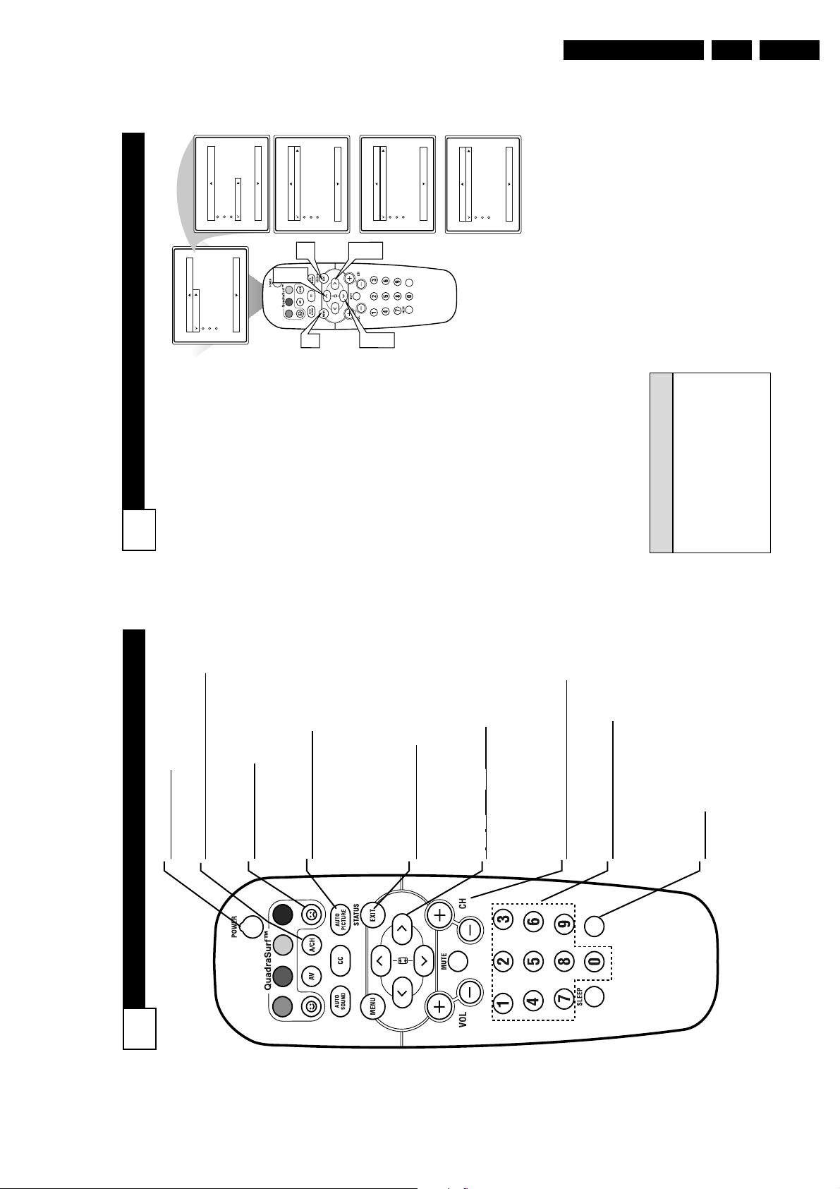
POWER Button
Press to turn the TV on or off.
A/CH
Button (Alternate Channel)
Press to toggle between the last viewed channel
and the channel presently being viewed.
FROWNIE Button
Allows you to delete channels from the “Quadra
Surf” lists for the colored buttons. Works with
all colored buttons.
AUT
O PICTURE Button
Press repeatedly to choose from 5 different fac-
tory predefined picture settings. Choose from
Personal (how you set the Picture Menu
Adjustment controls), Movies (for movies),
Sports (for any sporting event), Weak Signal
(used when the signal being received is not
great), or Multimedia (for video games).
ST
A
TUS/EXIT Button
Press to display the current channel number. If
the on-screen menu is displayed, press the
Status/Exit button of remove it from the TV’s
screen.
3
, 4, 1, and 2 Buttons
Press to navigate, select, and adjust controls
within the on-screen menu. Also use the CUR-
SOR 3 or CURSOR 4 to activate or deacti-
vate the EXPAND 4:3 screen formatting con-
trol.
CH(annel) + or
CH(annel)- Buttons
Press to select channels in ascending or
descending order.
NUMBERED
(0-9) Buttons
Press the numbered buttons to select TV chan-
nels or to enter certain values within the on-
screen menu. For single channel entries, press
the numbered button for the channel you desire.
The TV will pause for a second or two before
changing to the chosen channel.
CLOCK:
Press to display the “Timer” menu. Within this
menu, set the time, set the TV to tune to a cer-
tain channel at a certain time once or daily.
EN 11L04U AA 3.
VOL

EN 12 L04U AA3.
A
UTOMATICALLY
P
ROGRAM
13
Auto Program
Channel
12
Main
Picture
Sound
Features
Install
Brightness
Color
Picture
Sharpness
Tint
More...
Main
Picture
Sound
Features
Install
Language
Tuner Mode
Auto Program
Channel Edit
Install
Language
Tuner Mode
Auto Program
Channel Edit
Auto Program
Channel
13
Auto Program
Channel
14
VOL
2
4
2
4
1
6
3
5
Y
our TV can automatically set
itself for local area (or Cable
TV) channels. This makes it easy
for you to select only the TV sta-
tions in your area when the
CHANNEL (+), (–) buttons are
pressed.
Note: Make sure the antenna or
cable signal connection has been
completed before AUTOPRO-
GRAM is activated.
1
Press the MENU button on
the remote to show the on-
screen menu.
2
Press the CURSOR UP 3
or DOWN 4 buttons to
scroll through the on-screen
menu until the word Install
is highlighted.
3
Press the
CURSOR RIGHT
2 button
to display the
Install menu features.
4
Press CURSOR UP 3 or
DOWN 4 buttons to scroll
the Install features until the
words Auto Program are
highlighted.
5
Press the
CURSOR RIGHT
2 button
to start the Auto
Program scanning of chan-
nels. Auto Programming will
store all available channels
in the TV’s memory then
tune to the lowest available
channel when done.
6
When finished, press the
STATUS /EXIT button to
remove the menu from the
TV’s screen.
When CABLE is selected, channels 1-
125 are available.
When ANTENNAis selected, chan-
nels 2-69 are available.
When AUTO is selected, the TV will
automatically set itself to the correct
mode based on the type of signal it
detects when the AUTOPROGRAM
feature is activated.
H
ELPFUL
H
INTS
H
OW TO USE THE
T
UNER
M
ODE
C
ONTROL
12
T
he TUNER MODE control
allows you to change the TV’s
input signal to either ANTENNA,
CABLE, or AUTO mode. It’s
important for the TV to know
what type of signal to look for
(Cable TV or an Antenna). In the
AUTO mode, when the AUTO
PROGRAM feature is activated,
the TV will automatically choose
the correct mode.
1
Press the MENU button on
the remote to show the on-
screen menu.
2
Press the CURSOR UP 3
or DOWN 4 buttons to
scroll through the on-screen
menu until the word Install
is highlighted.
3
Press the CURSOR
RIGHT button to display
the Install menu features.
4
Press CURSOR UP 3 or
DOWN 4 buttons to scroll
the Install features until the
words TunerMode is high-
lighted.
5
Press the CURSOR
RIGHT button to select
either Antenna, Cable, or
Auto mode.6When finished, press the
STATUS /EXIT button to
remove the on-screen menu
from the TV’s screen.
When CABLE is selected, channels 1-
125 are available.
When ANTENNAis selected, chan-
nels 2-69 are available.
When AUTO is selected, the TV will
automatically set itself to the correct
mode based on the type of signal it
detects when the AUTOPROGRAM
feature is activated.
H
ELPFUL
H
INTS
Directions for Use
Main
Brightness
Color
Picture
Sound
Main
Picture
Features
Language
Tuner Mode
Picture
Sound
Sharpness
Tint
Install
Auto Program
Channel Edit
Features
Install
More...
Install
2
English
Language
Antenna
Tuner Mode
Auto Program
4
Channel Edit
English
English
Cable
OR
Language
Tuner Mode
Auto Program
Channel Edit
Install
6
3
VOL
2
1
4
Auto
OR
Language
Tuner Mode
Auto Program
Channel Edit
Install
Directions for Use
P
ICTURE
M
ENU
C
ONTROLS
15
Picture
Brightness
Color
Picture
Sharpness
Tint
Color Temp.
50
Brightness
65
Color
50
Picture
50
Sharpness
50
Color Temp.
Normal
Warm
or
Cool
DNR
On
Off
Tint
0
Contrast +
On
Off
T
o adjust your TV picture controls,
select a channel and use the
Picture Menu Controls listed below:
1
Brightness Control - Press the
CURSOR RIGHT 2 or LEFT
1 buttons until the darkest
parts of the picture are as bright
as you prefer.
2
Color Control - Press the
CURSOR RIGHT 2 or LEFT
1 buttons to add or eliminate
color.
3
Picture Control - Press the
CURSOR RIGHT 2 or LEFT
1 buttons until lightest parts of
the picture show good detail.
4
Sharpness Control - CURSOR
RIGHT 2 or LEFT 1 buttons
to improve detail in the picture.
5
Tint Control - Press the CUR-
SOR RIGHT 2 or LEFT 1
buttons to obtain natural skin
tones.
6
Color Temp Control - Press
the CURSOR RIGHT 2 or
LEFT 1 buttons to select
Normal, Cool, or Warm picture
preferences. (Normal will keep
the whites, white; Cool will
make the whites, bluish; and
Warm will make the whites, red-
dish.)
7
DNR Control - Press the
CURSOR RIGHT 2 or LEFT
1 buttons to turn DNR On or
Off. Dynamic Noise Reduction
helps to eliminate “noise” from
the picture.
8
Contrast + Control - Press the
CURSOR RIGHT 2 or LEFT
1 buttons to toggle the control
On or OFF. The Contrast + con-
trol helps to “sharpen” the pic-
ture quality. The black portions
of the picture become richer in
darkness and the whites become
brighter.
C
HANNEL
E
DIT
14
C
hannel Edit makes it easy for you to
ADD or DELETE channels from the
list of channels stored in the TV’s memory.
1
Press the MENU button on the
remote control to show the on-
screen menu.
2
Press the CURSOR UP3 or
DOWN 4 buttons to scroll though
the on-screen menu until the word
Install is highlighted.
3
Press the CURSOR RIGHT 2
button to display the Install menu
features.4Press the CURSOR UP3 or
DOWN 4 buttons to scroll through
the Install features until the words
Channel Edit are highlighted.
5
Press the CURSOR RIGHT 2
button to display the Channel Edit
options.6With the Channel Edit options
displayed, and Channel highlight-
ed; you can use the cursor buttons to
scroll through all available channels
that you wish to add (skipped OFF)
or delete (Skipped ON) from the
TV’s memory. You can also use the
NUMBERED buttons to go directly
to a specific numbered channel that
you want to add or skip. Or, you can
also use the CH+ or CH- to quickly
scan through the channels that have
not been skipped.
7
Using the CURSOR DOWN 4
button, scroll the menu to highlight
the word SKIPPED.
8
Now use the CURSOR RIGHT 2
to toggle between On or Off. If
ON is selected the channels is
skipped when scrolling channels
with the CH+ or CH- buttons. If
OFF is selected the channels is not
skipped when scrolling channels
with the CH+ or CH- buttons.
9
When finished, press the STA-
TUS/EXIT button to remove the
menu from the screen.
An “X” appearing in front of
any channel will indicate that
channel has skip on. When the
CH + or CH - buttons are used,
those channels will be skipped.
H
ELPFUL
H
INTS
EN 13L04U AA 3.
Off
On
Channel
Skipped
Channel Edit
Skipped
Channel
Channel Edit
8
Main
Brightness
Color
Picture
Sound
Main
Picture
Features
Language
Tuner Mode
Picture
Sound
Sharpness
Tint
Install
Auto Program
Channel Edit
Features
Install
More...
12
Channel
Skipped
Language
Tuner Mode
Auto Program
Channel Edit
Install
9
358
2
4
Channel
Skipped
Channel Edit
6
6
VOL
247
6
1
6

EN 14 L04U AA3.
VOL
1
1
4:3
Expand 4:3
M
any times while watching
movies from a DVD player the
image is shown in “letter box” for-
mat. This is the format that is
shown in movie theaters. when
shown on a TV screen, the image
will have areas of black on top and
bottom of the screen.
1
Press the CURSOR UP
3
or
DOWN
4
buttons to select
one of the two options 4:3 or
Expand 4:3.
4:3 - Standard format for the
TV.
Expand 4:3 - Enlarges the
picture to fill out the entire
screen area, eliminating the
“letter box” effect.
H
OW TO USE THE
4:3 E
XPAND
F
ORMAT
C
ONTROL
17
S
OUND
M
ENU CONTROLS
16
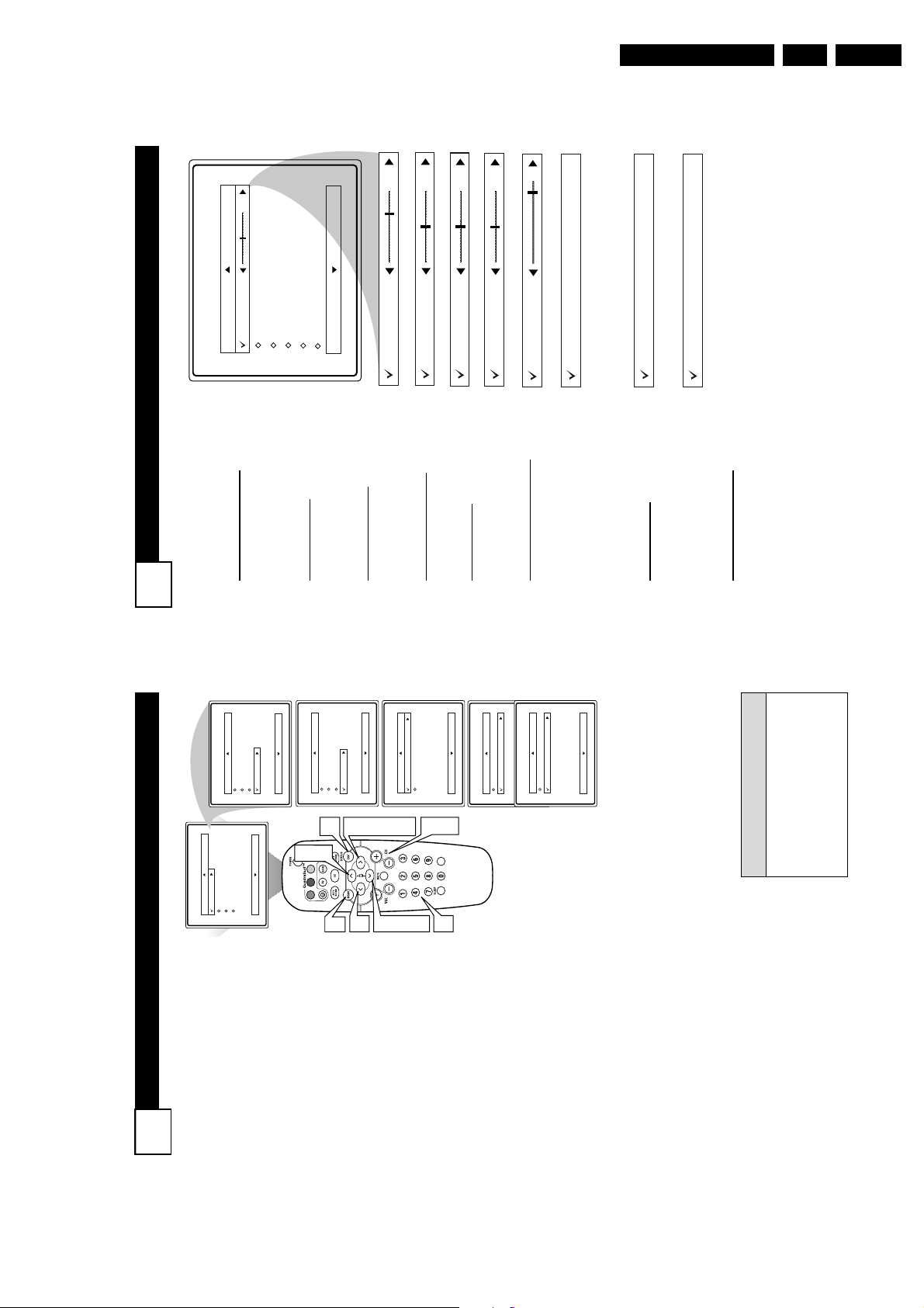
T
o adjust your TV sound, select and
use the Sound Menu Controls listed
below:
1
Treble: Press the
CURSOR
RIGHT 2 or LEFT 1 buttons
to adjust the control. The control
will enhance the high frequency
sounds.2Bass: Press the
CURSOR
RIGHT 2 or LEFT 1 buttons
to adjust the control. The control
will enhance the low frequency
sounds.
3
Balance: Press the
CURSOR
RIGHT 2 or LEFT 1 buttons
to adjust the level of sound com-
ing from the left and right speak-
ers.4AVL: (Auto Volume Leveler)
Press the
CURSOR RIGHT 2
or LEFT 1 buttons
to turn the
control On or Off. When On, AVL
will level out the sound being
heard when sudden changes in
volume occur during commercial
breaks or channel changes.
5
Incr . Surround:Press the
CUR-
SOR RIGHT 2 or LEFT 1 but-
tons
to select between Dolby
Virtual or Stereo settings (If
Stereo), or select Spatial or Mono
(If Mono).
6
SAP: Press the
CURSOR
RIGHT 2 or LEFT 1 buttons
to toggle this control to On or Off.
SAP is short for Secondary Audio
Programming and is sent as a
third audio channel, a SAP signal
can be heard apart from the cur-
rent TV program sound.Note: If
SAP is not present on a selected
show No SAP will appear on the
screen.7Sound: Press the
CURSOR
RIGHT 2 or LEFT 1 buttons
to select between Stereo or Mono
settings. Note: If Stereo is not
present on a selected show and the
TV is placed in the Stereo mode,
the sound coming from the TV
will remain in the Mono mode.
Directions for Use
Treble
Bass
Balance
AVL
Incr. Surround
More...
Picture
Sound
Features
Main
Install
50
Bass
R
L
Balance
50
Treble
On
or Off
Spatial
or Mono
Dolby Virtual
AVL
Incr. Surround
Incr. Surround
On
or Off
Mono
or Stereo
or Stereo
Sound
SAP

Directions for Use
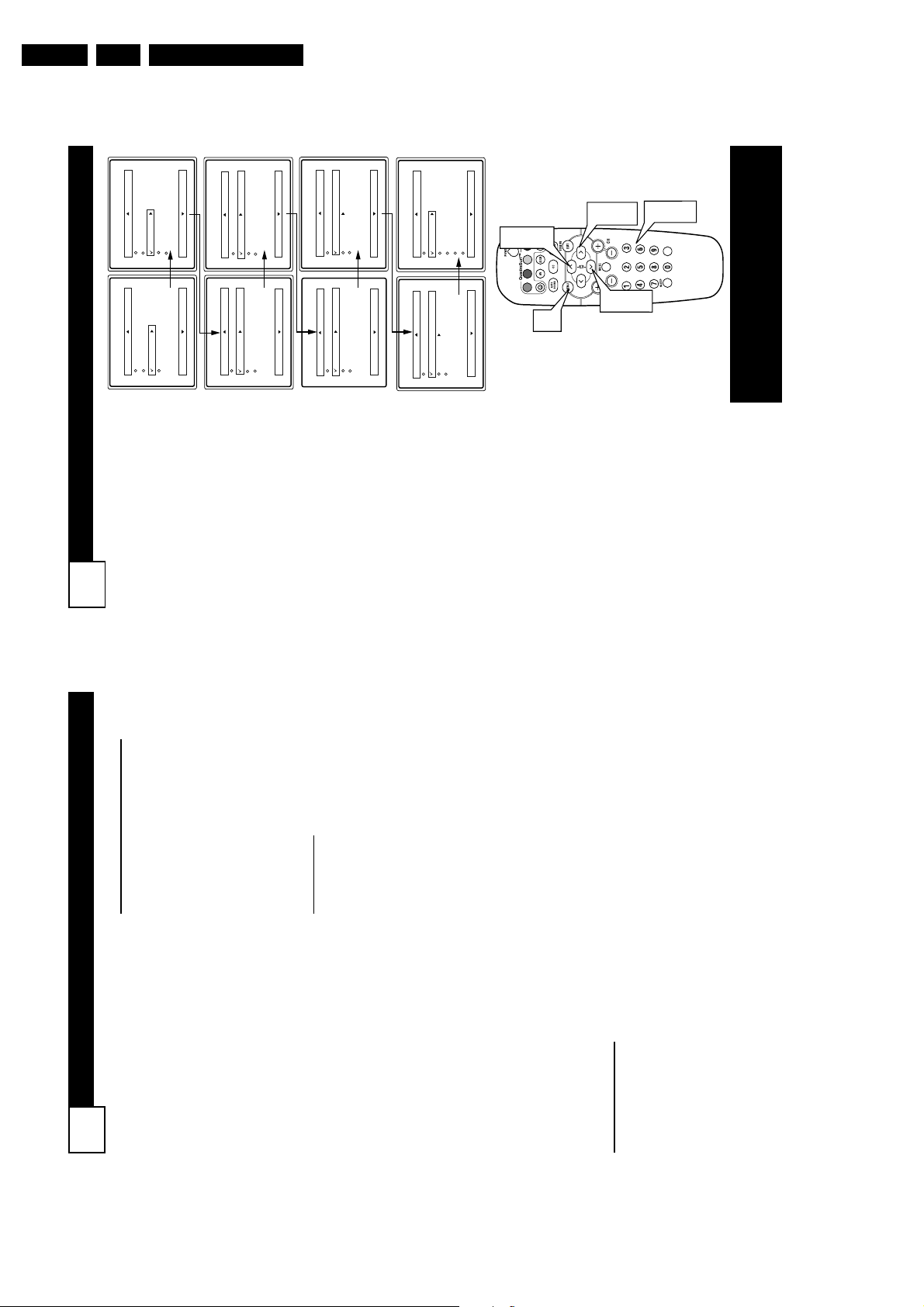
SETTING TV TO TURN ON OR OFF USING START OR STOP CONTROLS
19
Y
ou can set your TV to turn itself
on or off. You can set the TV to
turn itself On or Off once or at
the same time everyday. Follow
the steps below to set the Start and
Stop Time.
1
Press the MENU button on
the remote to show the on-
screen menu.
2
Press the CURSOR UP3 or
DOWN 4 buttons to scroll
through the on-screen menu
until the word Features is
highlighted.
3
Press the CURSOR RIGHT
2 button to display the
Features menu.4Press the CURSOR RIGHT
2 button to display the Timer
menu.5Press the CURSOR UP3 or
DOWN 4 buttons to scroll
through the Timer menu until
Start Time or Stop Time is
highlighted.
6
Enter the correct time by
using the Numbered buttons.
7
Press the CURSOR RIGHT
2 or CURSOR LEFT 1 but-
tons to change the AM or PM
setting.8When finished, press the
STATUS /EXIT button to
remove the on-screen menu
from the TV’s screen.
NOTE: The Activate Control must
be set to Once or Daily for the tele-
vision to turn On or Off at the speci-
fied time. See panel 21 for more
details.
VOL
Main
Picture
Sound
Features
Install
Brightness
Color
Picture
Sharpness
Tint
More...
Main
Picture
Sound
Features
Install
Timer
AutoLock
Active Control
Digi. Pic. Demo
Timer
Time
Start Time
Stop Time
Channel
Activate
Display
--:-- AM
Timer
Time
Start Time
Stop Time
Channel
Activate
Display
10:-- AM
Timer
Time
Start Time
Stop Time
Channel
Activate
Display
10:35 AM
Timer
Time
Start Time
Stop Time
Channel
Activate
Display
10:35 AM
Timer
Time
Start Time
Stop Time
Channel
Activate
Display
10:35 PM
Timer
Time
Start Time
Stop Time
Channel
Activate
Display
10:35 PM
8
2
5
347
1
2
5
6
7
Remember, be sure to press “0” and
then the hour number for single digit
entries.
You can get to the Clock setting by
pressing the Clock button on the
remote control.
The TV’s clock settings may be lost
when the TV is unplugged or when
AC power to the set is interrupted.
H
ELPFUL
H
INTS
NOTE: Active Control will only
appear in the menu of models
27PT6441/37 and 27PT6442/37.
S
ETTING THE
TV C
LOCK
U
SING
T
HE
T
IMER
C
ONTROL
18
Y
our television comes with an
on-screen clock. During nor-
mal operation, the clock appears
on the screen when the
STATUS/EXIT button is pressed or
if the Timer Display control is
turned On.
1
Press the MENU button on
the remote to show the on-
screen menu.
2
Press the CURSOR UP 3 or
DOWN 4 buttons to scroll
through the on-screen menu
until the word Features is
highlighted.
3
Press the CURSOR RIGHT
2 button to display the
Features menu.4Press the CURSOR RIGHT
2 button to display the
Timer menu.5Enter the correct time by
using the Numbered but-
tons.6Press the CURSOR RIGHT
2 or CURSOR LEFT 1
buttons to change the AM or
PM setting.
7
When finished, press the
STATUS /EXIT button to
remove the on-screen menu
from the TV’s screen.
NOTE: Active Control will only
appear in the menu of models
27PT6441/37 and 27PT6442/37.
Remember, be sure to press “0” and
then the hour number for single digit
entries.
You can get to the Clock setting by
pressing the Clock button on the
remote control.
The TV’s clock settings may be lost
when the TV is unplugged or when AC
power to the set is interrupted.
H
ELPFUL
H
INTS
EN 15L04U AA 3.
6
346
VOL
2
10:-- AM
Time
Start Time
Stop Time
Channel
Activate
Display
Timer
5
Timer
AutoLock
Active Control
Digi. Pic. Demo
Picture
Sound
Features
Install
Main
--:-- AM
Time
Start Time
Stop Time
Channel
Activate
Display
Timer
7
Brightness
Color
Picture
Sharpness
Tint
More...
Features
Install
Picture
Sound
Main
2
1
10:35 AM
Time
Start Time
Stop Time
Channel
Activate
Display
Timer
10:35 PM
Time
Start Time
Stop Time
Channel
Activate
Display
Timer

EN 16 L04U AA3.
A
CTIVATE
C
ONTROL
21
A
fter you have set the Time, Start
Time, Stop Time, and Start
Channel, the timer must be set to
come on Once or Daily, or turned Off
through the Activate control.
1
Press the MENU button on the
remote to show the on-screen
menu.2Press the CURSOR UP3 or
DOWN 4 buttons to scroll
through the on-screen menu
until the word Features is high-
lighted.3Press the CURSOR RIGHT 2
button to display the Features
menu.4Press the CURSOR UP3 or
DOWN 4 buttons to scroll
through the on-screen menu
until the word Timer is high-
lighted.5Press the CURSOR RIGHT 2
button to display the Timer
menu.6Press the CURSOR UP3 or
CURSOR DOWN 4 buttons
to highlight the Activate
Control.7Press the CURSOR RIGHT 2
or CURSOR LEFT 1 buttons
repeatedly to select Once, Daily,
or Off. 8When finished, press the STA-
TUS /EXIT button to remove
the on-screen menu from the
TV’s screen.
VOL
Main
Picture
Sound
Features
Install
Brightness
Color
Picture
Sharpness
Tint
More...
Main
Picture
Sound
Features
Install
Timer
AutoLock
Active Control
Digi. Pic. Demo
Timer
Time
Start Time
Stop Time
Channel
Activate Off
Display
8
357
1
Timer
Time
Start Time
Stop Time
Channel
Activate
Display
10:-- AM
7
246
OR
Timer
Time
Start Time
Stop Time
Channel
Activate Daily
Display
OR
Timer
Time
Start Time
Stop Time
Channel
Activate Once
Display
246
Remember, before setting the Timer con-
trols, the TV’s clock must be set to the
correct time, see panel 18 for details.
The TV’s clock settings may be lost when
the TV is unplugged or when AC power
to the set is interrupted.
You can get to the Clock setting by press-
ing the Clock button on the remote con-
trol.
H
ELPFUL
H
INTS
NOTE: Active Control will only
appear in the menu of models
27PT6441/37 and 27PT6442/37.
S
ETTING
TV
TO
S
TARTUP ON A
S
PECIFIC
C
HANNEL
20
Y
ou can select a specific channel
that the television will tune to
when the timer turns the set On.
Follow these steps to select the
channel.
1
Press the MENU button on
the remote to show the on-
screen menu.
2
Press the CURSOR UP3 or
DOWN 4 buttons to scroll
through the on-screen menu
until the word Features is
highlighted.
3
Press the CURSOR RIGHT
2 button to display the
Features menu.
4
With Timerselected, press the
CURSOR RIGHT 2 button
to display the Timer menu.
5
Press the CURSOR UP3 or
DOWN 4 buttons to scroll
through the Timer menu until
Channel is highlighted.
6
Press the Numbered buttons
to enter the desired start-up
channel. Or, press the CUR-
SOR RIGHT 2 or CURSOR
LEFT 1 or the CH+ or CH-
buttons repeatedly to enter the
start-up channel you want.
NOTE: The Activate Control must
be set to Once or Daily for this
Channel control to take effect.
7
When finished, press the
STATUS /EXIT button to
remove the on-screen menu
from the TV’s screen.
Remember, be sure to press “0” and
then the hour number for single digit
entries.
You can get to the Clock setting by
pressing the Clock button on the
remote control.
The TV’s clock settings may be lost
when the TV is unplugged or when
AC power to the set is interrupted.
H
ELPFUL
H
INTS
NOTE: Active Control will only
appear in the menu of models
27PT6441/37 and 27PT6442/37.
Directions for Use
Main
Brightness
Color
Picture
Sound
Timer
AutoLock
Active Control
Digi. Pic. Demo
Picture
Sound
Features
Install
Main
Picture
Sharpness
Tint
More...
Features
Install
10:-- AM
Time
Start Time
Stop Time
Channel 2
Activate
Time
Start Time
Stop Time
Channel
Activate
Display
Timer
7
346
2
5
VOL
1
2
6
Display
Timer
6
5
6

Directions for Use
A
CTIVE
C
ONTROL
O
PTIONS
23
T
he Active Control monitors
and adjusts incoming video
signals to help provide the best
picture quality.
When you choose to turn the
Active Control On, the picture
sharpness and noise reduction are
controlled automatically. Active
Control adjusts these picture set-
tings continuously and automati-
cally.
NOTE: Active Control is only
available in models 27PT6441/37
and 27PT6442/37.
1
Press the MENU button on
the remote to show the on-
screen menu.
2
Press the CURSOR UP 3
or DOWN 4 buttons to
scroll through the on-screen
menu until the word
Features is highlighted.
3
Press the CURSOR RIGHT
2 button to display the
Features menu.4Press the CURSOR UP 3
or DOWN 4 buttons to
repeatedly until Active
Control is highlighted.
5
Press the CURSOR RIGHT
2 or CURSOR LEFT 1
buttons to toggle the Active
Control On or Off. 6When finished, press the
STATUS /EXIT button to
remove the on-screen menu
from the TV’s screen.
VOL
Main
Picture
Sound
Features
Install
Brightness
Color
Picture
Sharpness
Tint
More...
Main
Picture
Sound
Features
Install
Timer
AutoLock
Active Control
Digi. Pic. Demo
6
3
5
1
5
2
4
Features
Timer
AutoLock
Active Control On
Digi. Pic. Demo
Features
Timer
AutoLock
Active Control Off
Digi. Pic. Demo
OR
2
4
NOTE: Active Control will only
appear in the menu of models
27PT6441/37 and 27PT6442/37.
H
OW TO
V
IEW
T
IME
U
SING THE
D
ISPLAY
C
ONTROL
22
A
fter the TV’s clock has been
set, you can use your TV as a
clock. The Display control allows
you to permanently display the
time in the upper right corner of
the screen.
1
Press the MENU button on
the remote to show the on-
screen menu.
2
Press the CURSOR UP 3 or
DOWN 4 buttons to scroll
through the on-screen menu
until the word Features is
highlighted.
3
Press the CURSOR RIGHT
2 button to display the
Features menu.4Press the CURSOR UP 3 or
DOWN 4 buttons to scroll
through the on-screen menu
until the word Timer is high-
lighted.5With Timer highlighted,
press the CURSOR RIGHT
2 button to display the
Timer menu.
6
Press the CURSOR UP 3 or
CURSOR DOWN 4 buttons
to highlight the Display
Control.7Press the CURSOR RIGHT
2 or CURSOR LEFT 1 but-
tons repeatedly to select On
or Off.
8
When finished, press the
STATUS /EXIT button to
remove the on-screen menu
from the TV’s screen.
NOTE: Active Control will only
appear in the menu of models
27PT6441/37 and 27PT6442/37.
EN 17L04U AA 3.
Main
Timer
AutoLock
Active Control
Digi. Pic. Demo
Picture
Sound
Features
Install
Main
Brightness
Color
Picture
Sharpness
Tint
More...
Picture
Sound
Features
Install
10:-- AM
Time
Timer
246
OR
Time
Start Time
Stop Time
Channel
Activate
Start Time
Stop Time
Channel
Activate
Display
8
357
VOL
7
246
1
Timer
Display On
Time
Start Time
Stop Time
Channel
Activate
Display Off
Timer
EN 18 L04U AA3.
S
ETTING
U
PAN
A
CCESS
C
ODE
25
O
ver the next few panels you’ll
learn how to block channels
and get a better understanding of
the rating terms for certain pro-
gramming.
First, let’s start by learning how to
set a personal access code:
1
Press the MENU button on
the remote to display the on-
screen menu.
2
Press the CURSOR UP
3
or
DOWN
4
buttons until the
word Features is highlighted.
3
Press the CURSOR RIGHT
2 button to display the
Features menu options.
4
Press the
CURSOR UP
3
or
DOWN
4
buttons
until the
words Auto Lock™ are high-
lighted.
5
Press the CURSOR RIGHT
2 button. The screen will
read, “Access Code - - - - .”6Using the NUMBERED but-
tons, enter 0, 7, 1, 1.
“XXXX” appears on the
Access Code screen as you
press the numbered buttons.
“Incorrect Code” will appear
on the screen, and you will
need to enter 0, 7, 1, 1 again.
7
The screen will ask you to
enter a “New Code.” Enter a
“new” 4 digit code using the
NUMBERED buttons. The
screen will then ask you to
CONFIRM the code you just
entered. Enter your new code
again. “XXXX” will appear
when you enter your new code
and then display the
AutoLock™ menu options.
Proceed to the next panel to learn
more...
Main
Picture
Sound
Features
Install
Timer
Rotation
AutoLock
Active Control
Digi. Pic. Demo
Features
Timer
Start Time
Stop Time
Channel
Activate
Display
Access Code
- - - -
AutoLock
Block Channel
Setup Code
Clear All
Block All
Movie Rating
TV Rating
OffStop Time
Channel
Activate
Display
Access Code
XXXX
Incorrect
New Code
- - - -
Confirm Code
XXXX
VOL
1
3
5
2
4
6
7
2
4
Timer
Rotation
AutoLock
Active Control
Digi. Pic. Demo
Access Code
XXXX
Features
Timer
AutoLock
Active Control
Digi. Pic. Demo
Features
Timer
AutoLock
Active Control
Digi. Pic. Demo
Features
Timer
AutoLock
Active Control
Digi. Pic. Demo
Features
Timer
AutoLock
Active Control
Digi. Pic. Demo
Features
Timer
AutoLock
Active Control
Digi. Pic. Demo
NOTE: Active Control will only appear
in the menu of models 27PT6441/37 and
27PT6442/37.
U
NDERSTANDING
A
UTO
L
OCK
C
ONTROLS
24
T
he AutoLock™ feature is an integrat-
ed circuit that receives and processes
data sent by broadcasters, or other pro-
gram providers, that contain program
content advisories. When programmed
by the viewer, a TV with AutoLock™ can
respond to the content advisories and
block program content that may be found
objectionable (such as offensive lan-
guage, violence, sexual situations, etc.).
This is a great feature to censor the type
of viewing children may watch.
AutoLock™ offers various BLOCK-
ING controls from which to choose:
Access Code - An Access Code must be
set to prevent children from unblocking
questionable or censored programming
set by their parents.
Channel Block - After an access code
has been programmed, you can block
individual channels including the A/V
inputs.
ClearAll - Allows you clear all channels
being blocked from your viewing set
with the Channel Block Control.
Block All - Allows you to block ALL
channels and A/Vinputs at one time.
Movie Ratings - Certain blocking
options exist which will block program-
ming based on ratings patterned by the
Motion Pictures Association of America.
TV Ratings - Just like the Movie
Ratings, programs can be blocked from
viewing using standard TV ratings set by
TV broadcasters.
MOVIE
RATINGS
G: General Audience - All ages admit-
ted. Most parents would find this pro-
gram suitable for all ages.
PG: Parental Guidance Suggested -
This programming contains material that
parents may find unsuitable for younger
children.
PG-13: Parents Strongly Cautioned -
This programming contains material that
parents may find unsuitable for children
under the age of 13.
MOVIE RATINGS Continued
R: Restricted - This is programming is
specifically designed for adults. Anyone
under the age of 17 should only view this
programming with an accompanying par-
ent or adult guardian.
NC-17: No one under the age of 17 will
be admitted. - This type of programming
should be viewed by adults only.
X: Adults Only - This type of program-
ming contains one or more of the follow-
ing: very graphic violence, very graphic
and explicit or indecent sexual acts, very
coarse and intensely suggestive language.
TV
RATINGS
TV-Y -- Designed for a very young audi-
ence, including children ages 2-6.
TV-Y7-- It may be appropriate for chil-
dren age 7 and above who have acquired
the development skills needed to distin-
guish between make-believe and reality.
TV-G -- Suitable for most audiences, this
type of programming contains little or no
violence, no strong language, and little or
no sexual dialogue or situations.
TV-PG -- This program contains material
that parents may find unsuitable for
younger children. Could contain Moderate
violence (V), some sexual situations (S),
infrequent coarse language (L), or some
suggestive dialogue (D).
TV-14 -- This program contains some
material that many parents would find
unsuitable for children under 14 years of
age. This type of programming contains
one or more of the following: intense vio-
lence (V), intense sexual situations (S),
strong coarse language (L), or intensely
suggestive dialogue (D).
TV-MA-- This program is specifically
designed to be viewed by adults and there-
fore may be unsuitable for children under
17. This type of programming contains one
or more of the following: graphic violence
(V), explicit sexual situations (S), or crude
indecent language (L).
Directions for Use

Directions for Use
BLOCK
/
CLEAR ALL CHANNELS AT THE SAME TIME
27
A
fter blocking specific channels
there may come a time when
you want to block or clear all the
channels at the same time.
Once you’ve entered your access
code and the AutoLock™ features
are displayed on the screen:
1
Press the CURSOR UP 3 or
DOWN 4 buttons to select
either Clear All or Block All.2If Clear All is selected, press
the CURSOR RIGHT 2
button to clear all blocked
channels. All channels will be
viewable.
If Block All is selected, press
the CURSOR RIGHT 2
button to turn the control On
or Off. When On is selected,
ALL available channels will
be blocked from viewing.
3
When finished, press the
STATUS/EXIT button to
remove the menu from the
screen.
NOTE: If you ever forget your
code, the 0, 7, 1, 1 code is the fac-
tory default and can be used to
enter and create a new access
code.
AutoLock
Block Channel
Setup Code
Clear All
Block All
Movie Rating
TV Rating
Clear ?Stop Time
Channel
Activate
Display
Clear All
Cleared
AutoLock
Block Channel
Setup Code
Clear All
Block All
Movie Rating
TV Rating
Off
Block All
On
VOL
1
1
2
3
B
LOCK
C
HANNELS
26
A
fter your personal access code
has been set (see previous
page), you are now ready to select
the channels or the A/V Inputs you
want to block out or censor.
Once you’ve entered your access
code and the AutoLock™ features
are displayed on the screen:
1
Press the CURSOR UP 3 or
DOWN 4 buttons until the
words Block Channel are
highlighted.2Press the CURSOR RIGHT
2 button to turn blocking
ON or OFF for that channel.
When ON is selected the
channel will be blocked.
3
Press the CH + or CH – but-
ton to select other channels
you wish to block. Repeat
steps 2-3 to block the new
channel.4When finished, press the
STATUS/EXIT button to
remove the menu from the
screen.
NOTE: If you ever forget your
code, the 0, 7, 1, 1 code is the fac-
tory default and can be used to
enter and create a new access code.
Enter your
Access Code to
view a tuned
channel that is
blocked with
Block Channel.
EN 19L04U AA 3.
OffStop Time
Channel
Block Channel
Setup Code
AutoLock
Activate
Display
Clear All
Block All
Movie Rating
TV Rating
On
Block Channel
Channel 12
Blocked By AutoLock
Channel Blocking
Access Code
- - - -
1
4
VOL
2
3
1

EN 20 L04U AA3.
TV R
ATINGS
29
T
he AutoLock™ feature can
block programming based on the
TV Industry ratings.
Once you’ve entered your access
code and the AutoLock™ features
are displayed on the screen:
1
Press the
CURSOR UP 3 or
DOWN 4 buttons
to high-
light the words TV Rating.
2
Press the
CURSOR RIGHT
2 button
to display the TV
Rating options (
TV-Y, TV -Y7,
TV-G, TV-PG, TV-14, or TV-
MA
).
3
Press the
CURSOR UP 3 or
DOWN 4 buttons
to high-
light any of the TV Rating
options. When highlighted, all
these options can be turned On
(which will allow blocking) or
Off (which will allow viewing).
NOTE: Some TV RATING options
also have sub-ratings. The ratings of
TV-Y7, TV-PG, TV-14, TV-MAcan
be customized to block V (violence),
FV (fantasy violence), S (sexual situa-
tions), L (coarse language), or D (sug-
gestive dialogue).
4
Press the
CURSOR RIGHT
2 button
on the remote to turn
the TV-Y or TV-G rating On or
Off. Or, press the
CURSOR
RIGHT 2 button
to enter the
sub-menus for the TV-Y7, TV-
PG, TV-14 or TV -MAratings.
5
If the TV-Y7, TV-PG, TV-14 or
TV-MA sub-menu is accessed,
press the
CURSOR UP 3 or
DOWN 4 buttons
to select
one of the options (Block All, V,
S, L, D, or FV).
6
Press the
CURSOR RIGHT
2 button
on the remote to
turn the option ON or OFF.
TV Rating
TV-Y
TV-Y7
TV-G
TV-PG
TV-14
TV-MA
Off
TV-Y
On
TV-Y7
Block All, FV
TV-G
Off
TV-14
Block All, V, S, L, D
TV-MA
Block All, V, S, L
TV-PG
Block All, V, S, L, D
VOL
1
3
5
1
3
5
2
4
6
M
OVIE
R
ATINGS
28
T
he AutoLock™ feature can
block programming based on
the Movie Industry ratings.
Once you’ve entered your access
code and the AutoLock™ features
are displayed on the screen:
1
Press the CURSOR UP 3 or
DOWN 4 buttons to high-
light the words Movie Rating.
2
Press the
CURSOR RIGHT
2 button
to display the
Movie Rating options (G,
PG, PG-13, R, NC17, or X).
3
Press the CURSOR UP 3 or
DOWN 4 buttons to high-
light any of the Movie Rating
options. When highlighted,
all these options can be
turned On (which will allow
blocking) or Off (which will
allow viewing).
4
Use the
CURSOR RIGHT 2
button
on the remote to turn
the rating option On or Off.
When a rating level is chosen to be
blocked, any higher level rating
will also be blocked from viewing.
(i.e.: If “R” is selected to be
blocked, NC-17 and X will auto-
matically be blocked.)
NOTE: If you ever forget your
code, the 0, 7, 1, 1 code is the fac-
tory default and can be used to
enter and create a new access
code.
Directions for Use
GPGPG-13RNC-17
Block Channel
Setup Code
Clear All
AutoLock
Block All
Movie Rating
Off
X
TV Rating
GPGPG-13RNC-17
Movie Rating
X
On
1
3
G
2
4
VOL
1
3

Directions for Use
C
LOSED
C
APTIONING
31
C
losed Captioning (CC) allows
you to read the voice content of
television programs on the TV
screen. Designed to help the hear-
ing impaired, this feature uses on-
screen “text boxes” to show dia-
logue and conversations while the
TV program is in progress.
1
Press the CC button on the
remote to display the current
Closed Caption setting.
2
Press the CC button repeat-
edly to choose from the four
Closed Caption options (CC
Off, CC1, CC2, CC Mute).
3
When finished, press the STA-
TUS /EXIT button to remove
the menu from the TV’s screen.
CC Mute
CC Off
CC1
CC2
CC Off
VOL
1
2
3
Y
our TV can be set to automati-
cally turn itself off at a given
amount of time.
1
Press the SLEEP button on
the remote control and the
SLEEP timer display will
appear on the screen.
2
Press the SLEEP button
repeatedly to pick the amount
of time (15, 30, 45, 60, 90, 120,
180, or 240 minutes) before the
TV will turn itself off.
NOTE: An on-screen count down
will appear during the last minute
before the TV shuts itself off. If any
button is pressed during the last
minute of the countdown, the
Sleeptimer setting will be cancelled.
Sleep 15
Sleep 30
Sleep 45
Sleep 60
Sleep 90
Sleep 120
Sleep 180
Sleep 240
Sleep 15
Sleep off
VOL
1
2
S
LEEPTIMER
BLOCKING OPTIONS
30
A
utoLock™ offers the viewer other block-
ing features as well. With these Blocking
Options, the censoring can be turned ON or
OFF.
Once you’ve entered your access code and
the AutoLock™ features are displayed on the
screen:
1
Press the CURSOR UP 3 or DOWN
4 buttons until the words Block
Options are highlighted.
2
Press the
CURSOR RIGHT 2 button
to
display the Blocking Options (Blocking,
Unrated, or No Rating) menu.
Blocking: Might be called the “master
switch” for AutoLock™. When On, ALL
blocking/censoring will take place. When Off,
ALL blocking is disabled.
Unrated: ALL unrated programs based on the
Movie Ratings or Parental (TV) Guidelines
can be blocked if this feature is set to On and
the Blocking feature is set to OFF.
No Rating: ALL programming with NO con-
tent advisory data can be blocked if set to On
and the Blocking feature is set to OFF.
3
Press the CURSOR UP 3 or DOWN
4 buttons to highlight the desired fea-
ture.
4
When highlighted, each feature can be
turned On or Off using the
CURSOR
RIGHT 2
or the
CURSOR LEFT 1
buttons
on the remote.
D
EMO
M
ODE
W
ith Demo Mode On, a split screen demo
will be shown on the screen. The Demo
Mode will show the right side wih show a
sharper image with more natural motion.
1
Press the MUTE button on the remote
approximately 3-4 seconds. The split
screen demo appears. After 20 seconds,
the TV will automatically reurn to nor-
mal operation.
Note: You can also turn the Digital Picture
Demo On or Off by using on-screen menu.
EN 21L04U AA 3.
2
4
1
On
On
On
Setup Code
Clear All
Block All
Movie Rating
TV Rating
AutoLock
Block Options
Blocking
Unrated
No Rating
3
4
VOL
1
3
Digi. Pic. Demo
VOL
1

EN 22 L04U AA3.
Q
UADRA
S
URF
33
T
he QuadraSurf™ control allows
you set up four different person-
al channel Surf lists using the col-
ored buttons (on the remote con-
trol), each holding up to ten chan-
nels in its quick viewing“list.”
1
Press the CHANNEL (+) or
(–) buttons (or the NUMBER
buttons) to select a channel to
add to one of the SURF lists.2Press the SMILEY button
on the remote control to ADD
the channel to one of the SURF
lists.3Press the corresponding COL-
ORED (Red, Green, Yellow or
Blue) button to add the channel
to that button’s Surf list. (Up to
ten channels per button can be
stored.)
Repeat steps 1 through 3 to add
additional channels (up to 10) to
each of the the SURF lists.
To remove a channel from one of
the SURF lists;
4
Press the COLORED
Quadra Surf button until the
desired channel appears. The
screen will display the channel
number with a colored
“Smiley” face to indicate the
Colored button it relates to.
5
While the “Smiley” face
channel indicator is dis-
played, press the FROWNIE
face button. The screen
will read, “Remove item? -
Press .”
6
Press the FROWNIE face
button again to confirm your
decision to remove the channel
from the Surf list.
Repeat steps 4-6 to remove other
channels from Surf lists.
12
Select List!
12
Added!
12
12
Remove Item? - Press
12
VOL
2
3
4
5
6
1
A
UTO
P
ICTURE
32
A
UTO
S
OUND
W
hether you’re watching a
movie or a sporting event,
your TV has automatic video con-
trol settings matched for your cur-
rent program source or content.
1
Press the AUTO PICTURE
button on the remote control.
The current Auto Picture set-
ting will be displayed on the
screen.2Press the AUTO PICTURE
button repeatedly to select
either Personal, Movies,
Sports, Weak Signal, or MUL-
TIMEDIA picture settings.
NOTE: The way you choose to set
the Picture Menu Controls will
become your Personal setting.
Movies - Preset picture options
for watching Video Tapes, or
DVDs.
Sports - Preset picture options
for watching sporting events.
Weak Signal - Preset picture
options for watching programs
where the reception is not at its
best.
Multimedia - Preset picture
options for use with video gam-
ing.
T
he Auto Sound feature allows
the listener to select between
four different factory set sound
options.
1
Press the AUTO SOUND
button on the remote control.
The current Auto Sound set-
ting will appear in the middle
of the screen.
2
Press the AUTO SOUND
button repeatedly to toggle
between the four settings.
(Personal, Theatre, Music, or
Voice)
NOTE: The way you choose to set
the Sound Menu Controls will
become your Personal setting.
Theatre - Preset sound
options for watching movies.
Dynamic Ultra Bass is includ-
ed in this option.
Music- Preset sound options
for musical programming
where there is little dialogue.
Dynamic Ultra Bass is includ-
ed in this option.
Voice - Preset sound options
for programming where heavy
dialogue is present.
Directions for Use
Sports
Movies
Personal
Multimedia
Weak Signal
1
2
VOL
Voice
Music
Theatre
Personal
VOL
1
2

Directions for Use
T
ROUBLESHOOTING
No Power
• Check the TV power cord. Unplug the TV, wait 10 seconds, then reinsert
the plug into the outlet and push the POWER button again.
• Check that the outlet is not on a wall switch.
• Be sure the fuse is not blown on the AC power strip, if one is being used.
No Picture
• Check antenna connections. Are they properly secured to the TV's ANT
751 plug?
• Check the TUNER MODE control for the correct tuner setting.
• Try running the Auto Program feature to find all available channels.
• Press the AV button on the remote to make sure the correct signal source is
selected (FRONT or Current Channel).
No Sound
• Check the VOLUME buttons.
• Check the MUTE button on the remote control.
• If you’re attempting to hook up auxiliary equipment, check the audio jack
connections located on the front of the TV.
Remote Does Not Work
• Check the batteries. If necessary, replace them with AAHeavy Duty (Zinc
Chloride) or Alkaline batteries.
• Clean the remote control and the remote control sensor window on the TV.
• Check the TV power cord. Unplug the TV, wait 10 seconds, then reinsert
the plug into the outlet and push the POWER button again.
• Be sure the fuse is not blown on the AC power strip, if one is being used.
• Check to be sure the TV outlet is not on a wall switch.
TV Displays Wrong Channel or No Channels Above 13
• Repeat channel selection.
• Add the desired channel numbers (using the CHANNEL EDIT control) into
the TV’s memory.
• Check to be sure the TUNER MODES are set to the CABLE option and run
the Auto Program feature to find all available channels.
35
Q
UADRA
S
URF
34
T
he Quadra Surf buttons on your
remote control allow you to store
up to 10 channels per button (40
total). You can even program the
A/V Input channels for each button
making them a “source” button.
Assuming channels have now been
added to the four Quadra Surf lists
(the four colored buttons, see the
previous page), let’s review how the
feature works.
1
Press one of the pre-pro-
grammed COLORED buttons
on the remote (Red, Green,
Yellow or Blue). The screen
will display a smiley face with
the first programmed channel
for that surf list.
2
While the colored “smiley”
face still appears on the
screen, press the same COL-
ORED button on the remote to
tune the second channel pro-
grammed for that specific surf
list.3Repeatedly pressing the same
COLORED button while the
“smiley” face appears will tune
all the programmed channels.
Pressing the COLORED button
again will return you to the first
channel in the list.
If the “smiley” face disappears from
the screen and the same COLORED
button is pressed, the surf channels
will be displayed starting with the
FIRST programmed channel again.
4
Repeat steps 1-3 for the other
three COLORED buttons (Surf
lists) if desired.
5
Any time the “smiley” face
appears with the channel num-
ber, pressing the “frownie”
face button will allow you to
remove it from the list (see the
previous page for more details).
EN 23L04U AA 3.
22
18
12
10
99
56
28
1
5
2
VOL
3
Remove Item? - Press
12
5
35
39
41
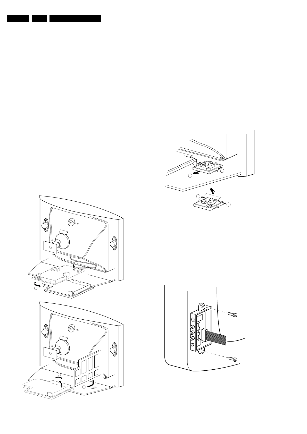
EN 24 L04U AA4.
Mechanical Instructions
4. Mechanical Instructions
Index of this chapter:
1. Set Disassembly
2. Service Position
3. Assy/Panel Removal
4. Set Re-assembly
Note: Figures below can deviate slightly from the actual
situation, due to different set executions.
4.1 Set Disassembly
Warning: Be sure to disconnect the AC power from the set
before opening it.
4.1.1 Rear Cover
1. Remove all fixation screws of the rear cover (do not forget
the screws that hold the rear connection panel).
2. Pull the rear cover backwards to remove it.
4.2 Service Position
Before placing the Mono Carrier in its service position, remove
the Front Interface assy/panel (see paragraph “Front Interface
Assy/Panel removal”) and the Side AV assy/panel (see
paragraph “Side AV Assy/Panel removal”).
1. Disconnect the degaussing coil [1].
2. Release the two fixation clamps (at the mid left and mid
right side of the bracket), and remove the bracket from the
bottom tray, by pulling it backwards [2].
3. Turn the chassis tray 90 degrees counter clockwise.
4. Move the panel bracket somewhat to the left and flip it 90
degrees [3], with the components towards the CRT.
5. Turn the panel bracket with the rear I/O toward the CRT.
6. Place the hook of the tray in the fixation hole of the cabinet
bottom [4] and secure it.
4.3 Assy/Panel Removal
4.3.1 Front Interface Assy/Panel Removal
1
1
2
3
3
E_14480_049.eps
110204
Figure 4-2 Front interface assy/panel removal
1. Remove the complete module from the bottom plate, by
pulling the two fixation clamps upward [1], while sliding the
module away from the CRT [2].
Note: these clamps are difficult to access.
2. Release the two fixation clamps [3] at the side of the
bracket, and lift the panel out of the bracket (it hinges at
1
one side).
4.3.2 Side AV Assy/Panel Removal
2
A
3
4
B
Figure 4-1 Service position Mono Carrier
E_14480_048.eps
110204
E_14480_050.eps
170204
Figure 4-3 Side AV assy/panel removal
1. Remove the two fixation screws, and remove the complete
Side AV assembly.
2. Release the two fixation clamps, and lift the panel out of the
bracket.

4.3.3 LTI/CTI Interface Panel Removal
Remove the LTI/CTI Interface panel from the Mono Carrier, by
disconnecting it from connector 1212.
4.3.4 Top Control Assy/Panel Removal
1. Remove the two fixation screws.
2. Push the assy a little bit upwards, and then pull it
backwards to release it from the front hinge.
3. Lift the panel from its bracket, while releasing the two
fixation clamps. The panel hinges on the other side.
4.3.5 Linearity Assy/Panel Removal
2
Mechanical Instructions
EN 25L04U AA 4.
Figure 4-4 Linearity assy/panel removal
1. Release the two fixation clamps [1] to lift the panel out of
the bracket [2].
4.4 Set Re-assembly
To re-assemble the whole set, do all processes in reverse
order.
Note: before you mount the rear cover, perform the following
checks:
1. Check whether the AC power cord is mounted correctly in
its guiding brackets.
2. Check whether all cables are replaced in their original
position
1
1
E_14480_051.eps
270204

EN 26 L04U AA5.
Service Modes, Error Codes, and Fault Finding
5. Service Modes, Error Codes, and Fault Finding
Index of this chapter:
1. Test Points
2. Service Modes
3. Problems and Solving Tips (related to CSM)
4. ComPair
5. Error Codes
6. The Blinking LED Procedure
7. Protections
8. Repair Tips
5.1 Test Points
This chassis is equipped with test points in the service printing.
In the schematics test points are identified with a rectangle box
around Fxxx or Ixxx. These test points are specifically
mentioned in the “Test Point Overview” as “half moons” with a
dot in the center.
Table 5-1 Test point overview
Test point Circuit Diagr.
F508, F535, F536, F537, F552, F561, F563, F573,
F664, I513, I518, I519, I524, I531, I533, I546
F401, F412, F413, F414, F418, F452, F453, F455,
F456, F458, F459, F460, F461, I408, I416, I417, I420,
I462, I468
F003, F004, I001, I002 Tuner IF A3
F201, F203, F205, F206 Hercules A4
F240, F241, F242 Features &
F952, F955, I951, I952 Audio Amplifier A7
F692 Front Control A9
F331, F332, F333, F338, F339, F341, F351, F353,
F354
F361, F362, F381, F382 ECO Scavem B2
Power supply A1
Line & Frame
Deflection
Connectivities
CRT Panel B1
Perform measurements under the following conditions:
• Television set in Service Default Alignment Mode.
• Video input: Color bar signal.
• Audio input: 3 kHz left channel, 1 kHz right channel.
5.2 Service Modes
Service Default mode (SDM) and Service Alignment Mode
(SAM) offers several features for the service technician, while
the Customer Service Mode (CSM) is used for communication
between the call center and the customer.
This chassis also offers the option of using ComPair, a
hardware interface between a computer and the TV chassis. It
offers the abilities of structured troubleshooting, error code
reading, and software version readout for all chassis.
Minimum requirements for ComPair: a Pentium processor, a
Windows OS, and a CD-ROM drive (see also paragraph
"ComPair").
5.2.1 Service Default Mode (SDM)
Purpose
• To create a predefined setting for measurements to be
made.
• To override software protections.
• To start the blinking LED procedure.
Specifications
• Tuning frequency: 61.25 MHz (channel 3).
• Color system: NTSC M.
• All picture settings at 50% (brightness, color contrast, hue).
• Bass, treble and balance at 50 %; volume at 25 %.
• All service-unfriendly modes (if present) are disabled. The
service unfriendly modes are:
– Timer / Sleep timer.
– Child / parental lock.
– Blue mute.
– Hotel / hospital mode.
– Auto shut off (when no “IDENT” video signal is
received for 15 minutes).
– Skipping of non-favorite presets / channels.
– Auto-storage of personal presets.
A2
– Auto user menu time-out.
– Auto Volume Leveling (AVL).
How to enter
To enter SDM, use one of the following methods:
A5
• Press the following key sequence on the remote control
transmitter: “062596” directly followed by the MENU button
(do not allow the display to time out between entries while
keying the sequence).
• Short jumper wires 9252 and 9275 on the family board (see
Fig. 8-1) and apply AC power. Then press the power button
(remove the short after start-up).
Caution: Entering SDM by shorting wires 9252 and 9275
will override the +8V-protection. Do this only for a short
period. When doing this, the service-technician must know
exactly what he is doing, as it could damage the television
set.
• Or via ComPair.
After entering SDM, the following screen is visible, with SDM in
the upper right corner of the screen to indicate that the
television is in Service Default Alignment Mode.
00028 L4LUS1 0.12 SDM
ERR 0 0 0 0 0
OP 000 057 140 032 120 128 000
Table 5-2 Software cluster overview
SW Cluster SW name UOC Type 12 NC Features
L4LUS1 L04US1_x.y TDA12000 9352 753 88557 CC+BTSC
L4LUS1 L04US1_x.y TDA12001 9352 753 89557 CC+BTSC+CMB+DW
L4LUS1 L04US1_x.y TDA12001 9352 753 35557 CC+BTSC+CMB
U= USA (NAFTA), S= Stereo dBx, CC= Closed Caption, BTSC= Broadcast
Television Systems Committee, CMB= Comb Filter, DW = Double Window
Figure 5-1 SDM menu
E_14480_066.eps
190204

Service Modes, Error Codes, and Fault Finding
EN 27L04U AA 5.
How to navigate
Use one of the following methods:
• When you press the MENU button on the remote control,
the set will switch on the normal user menu in the SDM
mode.
• On the TV, press and hold the VOLUME DOWN and press
the CHANNEL DOWN for a few seconds, to switch from
SDM to SAM and reverse.
How to exit
Switch the set to STANDBY by pressing the POWER button on
the remote control transmitter or the television set.
If you turn the television set off by removing the AC power (i.e.,
unplugging the television) without using the POWER button,
the television set will remain in SDM when AC power is reapplied, and the error buffer is not cleared.
5.2.2 Service Alignment Mode (SAM)
Purpose
• To change option settings.
• To display / clear the error code buffer.
• To perform alignments.
Specifications
• Operation hours counter (maximum five digits displayed).
• Software version, Error codes, and Option settings display.
• Error buffer clearing.
• Option settings.
• AKB switching.
• Software alignments (Tuner, White Tone, Geometry &
Audio).
• NVM Editor.
• ComPair Mode switching.
How to enter
To enter SAM, use one of the following methods:
• Press the following key sequence on the remote control
transmitter: “062596" directly followed by the OSD/
STATUS button (do not allow the display to time out
between entries while keying the sequence).
• Or via ComPair.
After entering SAM, the following screen is visible, with SAM in
the upper right corner of the screen to indicate that the
television is in Service Alignment Mode.
00028 L4LUS1 0.12 SAM
ERR 0 0 0 0 0
OP 000 057 140 032 120 128 000
. Clear Clear ?
. Options
. AKB On
. Tuner
. White Tone
. Geometry
. Audio
. NVM Editor
. ComPair on
Figure 5-2 SAM menu
E_14480_067.eps
190204
Menu explanation
1. LLLLL. This represents the run timer. The run timer counts
normal operation hours, but does not count standby hours.
2. AAABCD-X.Y. This is the software identification of the
main microprocessor:
– A= the project name (L04).
– B= the region: E= Europe, A= Asia Pacific, U= NAFTA,
L= LATAM.
– C= the software diversity:
• Europe: T= 1 page TXT, F= Full TXT, V= Voice
control.
• LATAM and NAFTA: N= Stereo non-dBx, S=
Stereo dBx.
• Asian Pacific: T= TXT, N= non-TXT, C= NTSC.
• ALL regions: M= mono, D= DVD, Q= Mk2.
– D= the language cluster number.
– X= the main software version number (updated with a
major change that is incompatible with previous
versions).
– Y= the sub software version number (updated with a
minor change that is compatible with previous
versions).
3. SAM. Indication of the Service Alignment Mode.
4. Error Buffer. Shows all errors detected since the last time
the buffer was erased. Five errors possible.
5. Option Bytes. Used to set the option bytes. See “Options”
in the Alignments section for a detailed description. Seven
codes are possible.
6. Clear. Erases the contents of the error buffer. Select the
CLEAR menu item and press the MENU RIGHT key. The
content of the error buffer is cleared.
7. Options. Used to set the option bits. See “Options” in the
Alignments section for a detailed description.
8. AKB. Used to disable (Off) or enable (On) the “black
current loop” (AKB= Auto Kine Bias).
9. Tuner. Used to align the tuner. See “Tuner” in the
Alignments section for a detailed description.
10. White Tone. Used to align the white tone. See “White
Tone” in the Alignments section for a detailed description.
11. Geometry. Used to align the geometry settings of the
television. See “Geometry” in the Alignments section for a
detailed description.
12. Audio. No audio alignment is necessary for this television
set.
13. NVM Editor. Can be used to change the NVM data in the
television set. See table “NVM data” further on.
14. ComPaIr. Can be used to switch on the television to In
System Programming (ISP) mode, for software uploading
via ComPair.
Caution: When this mode is selected without ComPair
connected, the TV will be blocked. Remove the AC power
to reset the TV.
How to navigate
• In SAM, select menu items with the MENU UP/DOWN keys
on the remote control transmitter. The selected item will be
highlighted. When not all menu items fit on the screen, use
the MENU UP/DOWN keys to display the next / previous
menu items.
• With the MENU LEFT/RIGHT keys, it is possible to:
– Activate the selected menu item.
– Change the value of the selected menu item.
– Activate the selected submenu.
• In SAM, when you press the MENU button twice, the set
will switch to the normal user menus (with the SAM mode
still active in the background). To return to the SAM menu
press the MENU or STATUS/EXIT button.
• When you press the MENU key in while in a submenu, you
will return to the previous menu.
How to store SAM settings
To store the settings changed in SAM mode, leave the top level
SAM menu by using the POWER button on the remote control
transmitter or the television set.

EN 28 L04U AA5.
Service Modes, Error Codes, and Fault Finding
How to exit
Switch the set to STANDBY by pressing the POWER button on
the remote control transmitter or the television set.
If you turn the television set “off” by removing the AC power
(i.e., unplugging the television) without using the POWER
button, the television set will remain in SAM when AC power is
re-applied, and the error buffer is not cleared.
5.2.3 Customer Service Mode (CSM)
Purpose
The Customer Service Mode shows error codes and
information on the TV’s operation settings. The call center can
instruct the customer (by telephone) to enter CSM in order to
identify the status of the set. This helps the call center to
diagnose problems and failures in the TV set before making a
service call.
The CSM is a read-only mode; therefore, modifications are not
possible in this mode.
How to enter
To enter CSM, press the following key sequence on the remote
control transmitter: “123654” (do not allow the display to time
out between entries while keying the sequence).
Upon entering the Customer Service Mode, the following
screen will appear:
1 00028 L4LUS1 0.12 CSM
2 CODES 0 0 0 0 0
3 OP 000 057 140 032 120 128 000
4 nnXXnnnn/nnX
5 P3C-1
6 NOT TUNED
7 NTSC
8 STEREO
9 CO 50 CL 50 BR 50 HU 0
0 AVL Off BS 50
• Press the MENU, STATUS/EXIT, or POWER button on the
remote control transmitter.
• Press the POWER button on the television set.
5.3 Problems and Solving Tips Related to CSM
5.3.1 Picture Problems
Note: The problems described below are all related to the TV
settings. The procedures used to change the value (or status)
of the different settings are described.
Picture too dark or too bright
If:
• The picture improves when you have press the AUTO
PICTURE button on the remote control transmitter, or
• The picture improves when you enter the Customer
Service Mode,
Then:
1. Press the AUTO PICTURE button on the remote control
transmitter repeatedly (if necessary) to choose
PERSONAL picture mode.
2. Press the MENU button on the remote control transmitter.
This brings up the normal user menu.
3. In the normal user menu, use the MENU UP/DOWN keys
to highlight the PICTURE sub menu.
4. Press the MENU LEFT/RIGHT keys to enter the PICTURE
sub menu.
5. Use the MENU UP/DOWN keys (if necessary) to select
BRIGHTNESS.
6. Press the MENU LEFT/RIGHT keys to increase or
decrease the BRIGHTNESS value.
7. Use the MENU UP/DOWN keys to select PICTURE.
8. Press the MENU LEFT/RIGHT keys to increase or
decrease the PICTURE value.
9. Press the MENU button on the remote control transmitter
twice to exit the user menu.
10. The new PERSONAL preference values are automatically
stored.
White line around picture elements and text
E_14480_068.eps
190204
Figure 5-3 CSM menu
Menu explanation
1. Indication of the decimal value of the operation hours
counter, Software identification of the main microprocessor
(see "Service Default or Alignment Mode" for an
explanation), and the service mode (CSM= Customer
Service Mode).
2. Displays the last five errors detected in the error code
buffer.
3. Displays the option bytes.
4. Displays the type number version of the set.
5. Reserved item for P3C call centers (AKBS stands for
Advanced Knowledge Base System).
6. Indicates the television is receiving an "IDENT" signal on
the selected source. If no "IDENT" signal is detected, the
display will read "NOT TUNED"
7. Displays the detected Color system (e.g. PAL/NTSC).
8. Displays the detected Audio (e.g. stereo/mono).
9. Displays the picture setting information.
10. Displays the sound setting information.
How to exit
To exit CSM, use one of the following methods:
If:
The picture improves after you have pressed the AUTO
PICTURE button on the remote control transmitter,
Then:
1. Press the AUTO PICTURE button on the remote control
transmitter repeatedly (if necessary) to choose
PERSONAL picture mode.
2. Press the MENU button on the remote control transmitter.
This brings up the normal user menu.
3. In the normal user menu, use the MENU UP/DOWN keys
to highlight the PICTURE sub menu.
4. Press the MENU LEFT/RIGHT keys to enter the PICTURE
sub menu.
5. Use the MENU UP/DOWN keys to select SHARPNESS.
6. Press the MENU LEFT key to decrease the SHARPNESS
value.
7. Press the MENU button on the remote control transmitter
twice to exit the user menu.
8. The new PERSONAL preference value is automatically
stored.
Snowy picture
Check CSM line 6. If this line reads “Not Tuned”, check the
following:
• Antenna not connected. Connect the antenna.
• No antenna signal or bad antenna signal. Connect a proper
antenna signal.

Service Modes, Error Codes, and Fault Finding
EN 29L04U AA 5.
• The tuner is faulty (in this case line 2, the Error Buffer line,
will contain error number 10). Check the tuner and replace/
repair the tuner if necessary.
Black and white picture
If:
• The picture improves after you have pressed the AUTO
PICTURE button on the remote control transmitter,
Then:
1. Press the AUTO PICTURE button on the remote control
transmitter repeatedly (if necessary) to choose
PERSONAL picture mode.
2. Press the MENU button on the remote control transmitter.
This brings up the normal user menu.
3. In the normal user menu, use the MENU UP/DOWN keys
to highlight the PICTURE sub menu.
4. Press the MENU LEFT/RIGHT keys to enter the PICTURE
sub menu.
5. Use the MENU UP/DOWN keys to select COLOR.
6. Press the MENU RIGHT key to increase the COLOR value.
7. Press the MENU button on the remote control transmitter
twice to exit the user menu.
8. The new PERSONAL preference value is automatically
stored.
Menu text not sharp enough
If:
• The picture improves after you have pressed the AUTO
PICTURE button on the remote control transmitter,
Then:
1. Press the AUTO PICTURE button on the remote control
transmitter repeatedly (if necessary) to choose
PERSONAL picture mode.
2. Press the MENU button on the remote control transmitter.
This brings up the normal user menu.
3. In the normal user menu, use the MENU UP/DOWN keys
to highlight the PICTURE sub menu.
4. Press the MENU LEFT/RIGHT keys to enter the PICTURE
sub menu.
5. Use the MENU UP/DOWN keys to select PICTURE.
6. Press the MENU LEFT key to decrease the PICTURE
value.
7. Press the MENU button on the remote control transmitter
twice to exit the user menu.
8. The new PERSONAL preference value is automatically
stored.
5.4 ComPair
5.4.1 Introduction
ComPair (Computer Aided Repair) is a service tool for Philips
Consumer Electronics products. ComPair is a further
development on the European DST (service remote control),
which allows faster and more accurate diagnostics. ComPair
has three big advantages:
• ComPair helps you to quickly get an understanding on how
to repair the chassis in a short time by guiding you
systematically through the repair procedures.
• ComPair allows very detailed diagnostics (on I2C level)
and is therefore capable of accurately indicating problem
areas. You do not have to know anything about I2C
commands yourself because ComPair takes care of this.
• ComPair speeds up the repair time since it can
automatically communicate with the chassis (when the
microprocessor is working) and all repair information is
directly available. When ComPair is installed together with
the SearchMan electronic manual of the defective chassis,
schematics and PWBs are only a mouse click away.
5.4.2 Specifications
ComPair consists of a Windows based faultfinding program
and an interface box between PC and the (defective) product.
The ComPair interface box is connected to the PC via a serial
or RS232 cable.
In this chassis, the ComPair interface box and the TV
communicate via a bi-directional service cable via the service
connector.
The ComPair faultfinding program is able to determine the
problem of the defective television. ComPair can gather
diagnostic information in two ways:
• Automatic (by communication with the television):
ComPair can automatically read out the contents of the
entire error buffer. Diagnosis is done on I2C level. ComPair
can access the I2C bus of the television. ComPair can
send and receive I2C commands to the micro controller of
the television. In this way, it is possible for ComPair to
communicate (read and write) to devices on the I2C
busses of the TV-set.
• Manually (by asking questions to you): Automatic
diagnosis is only possible if the micro controller of the
television is working correctly and only to a certain extend.
When this is not the case, ComPair will guide you through
the faultfinding tree by asking you questions (e.g. Does the
screen give a picture? Click on the correct answer: YES /
NO) and showing you examples (e.g. Measure test-point I7
and click on the correct waveform you see on the
oscilloscope). You can answer by clicking on a link (e.g.
text or a waveform picture) that will bring you to the next
step in the faultfinding process.
By a combination of automatic diagnostics and an interactive
question / answer procedure, ComPair will enable you to find
most problems in a fast and effective way.
Beside fault finding, ComPair provides some additional
features like:
• Up- or downloading of pre-sets.
• Managing of pre-set lists.
• Emulation of the Dealer Service Tool (DST).
• If both ComPair and SearchMan (Electronic Service
Manual) are installed, all the schematics and the PWBs of
the set are available by clicking on the appropriate
hyperlink.
Example: Measure the DC-voltage on capacitor C2568
(Schematic/Panel) at the Mono-carrier.
– Click on the “Panel” hyperlink to automatically show
the PWB with a highlighted capacitor C2568.
– Click on the “Schematic” hyperlink to automatically
show the position of the highlighted capacitor.
• Software downloading (as soon as this is supported by
ComPair).
5.4.3 How To Connect
1. First, install the ComPair Browser software (see the Quick
Reference Card for installation instructions).
2. Connect the RS232 interface cable between a free serial
(COM) port of your PC and the PC connector (marked with
“PC”) of the ComPair interface.
3. Connect the mains adapter to the supply connector
(marked with “POWER 9V DC”) of the ComPair interface.
4. Switch the ComPair interface “off”.
5. Switch the television set “off” with the Power switch.
6. Connect the ComPair interface cable between the
connector on the rear side of the ComPair interface
(marked with “I2C”) and the ComPair (or Service)
connector at the rear side of the TV (for its location see
figure 8 item “D”).
7. Plug the mains adapter in a mains outlet, and switch the
interface “on”. The green and red LEDs light up together.
The red LED extinguishes after approx. 1 second while the
green LED remains lit.
 Loading...