

Philips ISP1581 User Manual

UM10016_3
Semiconductors
ISP1581 Hi-Speed USB MPEG2 Encoder Reference Kit
Rev. 03.00 — 12 April 2004 User manual
Document information
Info Content
Keywords
Abstract
ISP1581, USB, universal serial bus, MPEG, peripheral controller
This document explains the use of the Philips ISP1581 Hi-Speed
Universal Serial Bus (USB) MPEG2 Encoder Reference demo board in
terms of jumper settings and connector pin assignments. A basic board
testing procedure is also provided.

Philips Semiconductors
ISP1581 Hi-Speed USB MPEG2 Encoder Reference Kit
UM10016_3
Revision history
Rev
3.0 April 2004 - Updated Section 2.
2.0 December 2003 Changed the power supply input voltage from 5 V to 12 V:
1.0 January 2003 USB MPEG2 Encoder Reference Kit first release
Date Description
- Changed terminology from “interface device” to “peripheral controller”.
• Table 8-2
• Section 7.6
• Section 12.
Contact information
For additional information, please visit: http://www.semiconductors.philips.com/
For sales office addresses, please send an email to: sales.addresses@www.semiconductors.philips.com
User manual Rev. 03.00 — 12 April 2004 2 of 28
© Koninklijke Philips Electronics N.V. 2004. All rights reserved.

Philips Semiconductors
This is a legal agreement between you (either an individual or an entity) and Philips Semiconductors. By accepting
this product, you indicate your agreement to the disclaimer specified as follows:
ISP1581 Hi-Speed USB MPEG2 Encoder Reference Kit
UM10016_3
DISCLAIMER
PRODUCT IS DEEMED ACCEPTED BY RECIPIENT. THE PRODUCT IS PROVIDED “AS IS” WITHOUT
WARRANTY OF ANY KIND. TO THE MAXIMUM EXTENT PERMITTED BY APPLICABLE LAW, PHILIPS
SEMICONDUCTORS FURTHER DISCLAIMS ALL WARRANTIES, INCLUDING WITHOUT LIMITATION ANY
IMPLIED WARRANTIES OF MERCHANT ABILITY, FITNESS FOR A PARTICULAR PURPOSE, AND
NONINFRINGEMENT. THE ENTIRE RISK ARISING OUT OF THE USE OR PERFORMANCE OF THE
PRODUCT AND DOCUMENTATION REMAINS WITH THE RECIPIENT. TO THE MAXIMUM EXTENT
PERMITTED BY APPLICABLE LAW, IN NO EVENT SHALL PHILIPS SEMICONDUCTORS OR ITS SUPPLIERS BE
LIABLE FOR ANY CONSEQUENTIAL, INCIDENTAL, DIRECT, INDIRECT, SPECIAL, PUNITIVE, OR OTHER
DAMAGES WHATSOEVER (INCLUDING, WITHOUT LIMITATION, DAMAGES FOR LOSS OF BUSINESS
PROFITS, BUSINESS INTERRUPTION, LOSS OF BUSINESS INFORMATION, OR OTHER PECUNIARY LOSS)
ARISING OUT OF THIS AGREEMENT OR THE USE OF OR INABILITY TO USE THE PRODUCT, EVEN IF
PHILIPS SEMICONDUCTORS HAS BEEN ADVISED OF THE POSSIBILITY OF SUCH DAMAGES.
User manual Rev. 03.00 — 12 April 2004 3 of 28
© Koninklijke Philips Electronics N.V. 2004. All rights reserved.

Philips Semiconductors
ISP1581 Hi-Speed USB MPEG2 Encoder Reference Kit
UM10016_3
Contents
1. Introduction...............................................................................................................................................................................6
2. System Requirements...............................................................................................................................................................6
3. Connection Diagram................................................................................................................................................................6
4. PCBA View.................................................................................................................................................................................7
5. Device Driver and Application Software.............................................................................................................................7
5.1. Introduction......................................................................................................................................................................7
5.2. Preparing for Software Installation...............................................................................................................................8
5.2.1. Installing the Device Driver..................................................................................................................................8
5.2.2. Installing the Decoder............................................................................................................................................8
5.3. Using the Application Software....................................................................................................................................9
5.3.1. Board Initialization..................................................................................................................................................9
5.3.2. Running the Application......................................................................................................................................11
6. Advanced Debugging Function.............................................................................................................................................12
6.1. Using Advanced Debugging Function ........................................................................................................................12
6.2. Using the SAA7114 Button..........................................................................................................................................12
6.3. Using the SAA6752 Button..........................................................................................................................................13
6.4. Using the I2C Control Button.....................................................................................................................................13
6.5. Using the SW Reset Button ........................................................................................................................................13
7. Hardware Description...........................................................................................................................................................14
7.1. Video-Input Interface....................................................................................................................................................14
7.2. Analog Audio-Input Interface......................................................................................................................................14
7.3. MPEG Stream (PS Stream) Output Interface...........................................................................................................14
7.4. I2C-Bus Interface............................................................................................................................................................14
7.5. USB Device Endpoints..................................................................................................................................................15
7.6. Power Supply..................................................................................................................................................................15
8. Connector Pin information...................................................................................................................................................15
9. Jumper and Test Points.........................................................................................................................................................16
10. LED Indicators....................................................................................................................................................................17
11. RESET Switches..................................................................................................................................................................17
12. Schematics............................................................................................................................................................................17
13. Bill of Materials...................................................................................................................................................................27
14. Known Issues......................................................................................................................................................................28
15. References...........................................................................................................................................................................28
User manual Rev. 03.00 — 12 April 2004 4 of 28
© Koninklijke Philips Electronics N.V. 2004. All rights reserved.

Philips Semiconductors
ISP1581 Hi-Speed USB MPEG2 Encoder Reference Kit
UM10016_3
Microsoft and Windows are either registered trademarks or trademarks of Microsoft Corp. in the United States
and/or other countries. The names of actual companies and products ment ion ed herein may be the trademarks of
their respective owners. All other names, products, and trademarks are the property of their respective owners.
User manual Rev. 03.00 — 12 April 2004 5 of 28
© Koninklijke Philips Electronics N.V. 2004. All rights reserved.
Philips Semiconductors
1. Introduction
The Philips ISP1581 Hi-Speed Universal Serial Bus (USB) MPEG2 Encoder Reference Kit is a
development tool that consists of an MPEG2 encoder demo board, firmware source code for the
onboard microcontroller, and a complete set of documents. This kit guides you in how analog
video signals from various sources (S-Video or composite signal) are converted to digital video
signals, which are then compressed to an MPEG2 bitstream by the onboard MPEG2 encoder
chip. The bitstream is transferred to the PC through a high-speed USB pipe. Th is kit is very
suitable for video capture card applications and digital video (DV) applications.
This document explains the use of the demo board in terms of jumper settings and connector
pin assignments. A basic board testing procedure is also provided.
2. System Requirements
• Requires a PC with the following configurations:
o An 800 MHz Pentium III (or equivalent) CPU or faster
o A Video Graphics Adaptor (VGA) card with video resolution of 800 x 600 or greater
UM10016_3
ISP1581 Hi-Speed USB MPEG2 Encoder Reference Kit
o A sound card
o A hard disk with 300 Mbytes or greater free space
o System memory size of 128 Mbytes or greater
o A Hi-Speed USB Host Controller
o Microsoft Visual C++.
• Operating system supported: Microsoft
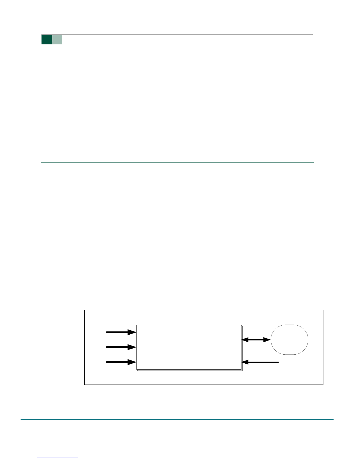
3. Connection Diagram
To perform a functionality test, an Audio/Video (AV) source device is required. Its audi o and
video output signals should be connected to the audio and video input jacks of the demo board,
respectively. See Figure 3-1.
Audio In cable
CVBS In Cable
S-video In Cable
®
Windows® 2000 and Microsoft Windows XP.
USB
MPEG2 Encoder Demo Board
USB Cable
Computer
DC Power Supply In
User manual Rev. 03.00 — 12 April 2004 6 of 28
Figure 3-1: Connection Block Diagram
© Koninklijke Philips Electronics N.V. 2004. All rights reserved.
Philips Semiconductors
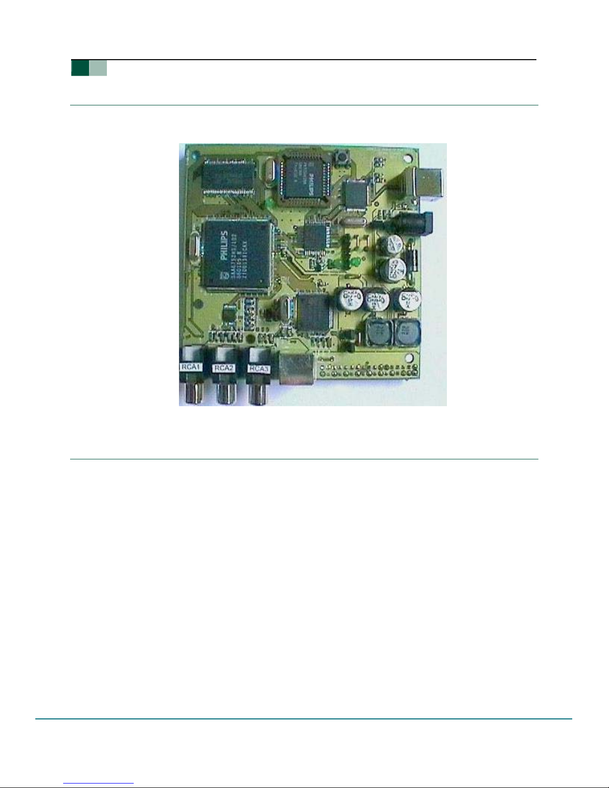
4. PCBA View
Figure 4-1 shows the printed circuit board (PCB) assembly of a USB MPEG2 Enco d er reference
kit designed using the Philips ISP1581.
UM10016_3
ISP1581 Hi-Speed USB MPEG2 Encoder Reference Kit
Figure 4-1: PCB Assembly
5. Device Driver and Application Software
5.1. Introduction
The device driver and the application software are stored on a source diskette in
mpegtestsuite.zip. The source diskette contains the following files:
• mpegtestsuite.zip
• readme.txt
Unzip mpegtestsuite.zip, you will obtain the following directory structure:
<drive>:\Application\
•
<drive>:\Driver\
•
<drive>:\InitFiles\
•
<drive>:\Decoder\
•
User manual Rev. 03.00 — 12 April 2004 7 of 28
© Koninklijke Philips Electronics N.V. 2004. All rights reserved.

Philips Semiconductors
5.2. Preparing for Software Installation
Create a directory called “C:\philipsMpeg\”1, and move the following three unzipped directories
to this directory.
<drive>:\Application\
•
<drive>:\Driver\
•
•
<drive>:\Decoder\
UM10016_3
ISP1581 Hi-Speed USB MPEG2 Encoder Reference Kit
Copy files in directory “
<drive>:\InitFiles\*.*” to directory “C:\philipsMpeg”. By default, the
application software searches initial files under directory C:\philipsMpeg and, therefore,
whenever the device is initialized, the application pro mpts for the current path of the file.
Note: Copy file MSVCRTD.DLL from the Application directory to the WINNT\System32\
directory, if the file is not present on your PC.
5.2.1. Installing the Device Driver
Connect the device to the system. When the system prompts for the INF file, redirect the
system to the C:\philipsMpeg\Driver directory and load the driver by using the INF file.
5.2.2. Installing the Decoder
To install the supplied decoder, run the “register.bat” DO S batch file. This file can be found in
directory C:\philipsMpeg\Decoder. The decoder consists of eight software components.
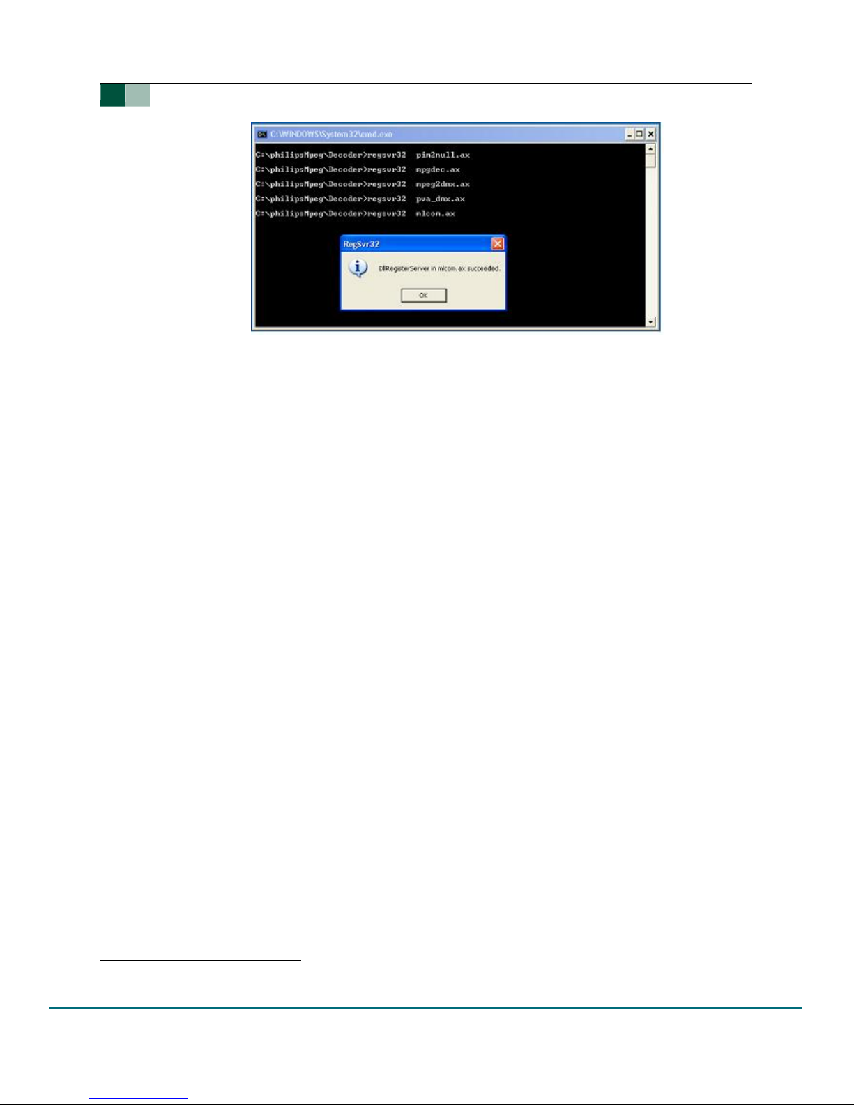
The contents of the register.bat batch file are:
• regsvr32 pim2null.ax
• regsvr32 mpgdec.ax
• regsvr32 mpeg2dmx.ax
• regsvr32 pva_dmx.ax
• regsvr32 mlcom.ax
• regsvr32 windivx.ax
• regsvr32 ball.ax
• regsvr32 mpg2splt.ax.
1
It is strictly recommended to name the directory as philipsMpeg and must be located under the C drive.
User manual Rev. 03.00 — 12 April 2004 8 of 28
© Koninklijke Philips Electronics N.V. 2004. All rights reserved.
Philips Semiconductors
When running the DOS batch file, carefully check messages (see Figure 5-1) to ensure that all
components are successfully loaded.
5.3. Using the Application Software
This application software handles board initialization and MPEG2 stream transfer. Before running
this application, make sure that all the cables are connected and A/V sources are present. For
details on connection, see Section 8.
UM10016_3
ISP1581 Hi-Speed USB MPEG2 Encoder Reference Kit
Figure 5-1: Contents of the register.bat Batch File
The initialization process is explained in the following sections.
5.3.1. Board Initialization
You can start the application software either by double-clicking the MPEG.exe1 icon present in
the C:\PhilipsMPEG directory, or by double-clicking the MPEG.exe icon on your desktop if you
have already created a shortcut.
To initialize the board, select a proper TV standard under the Capture menu. For example:
Initialize PAL (see Figure 5-2) or Initialize NTSC (see Figure 5-3). S-Video is a default video
input source.
1
In this document, items that you click or type are indicated in bold.
User manual Rev. 03.00 — 12 April 2004 9 of 28
© Koninklijke Philips Electronics N.V. 2004. All rights reserved.
 Loading...