

Page 1
UM10005_3
ISP1561 Evaluation Board
User’s Guide
April 2003
User’s Guide
Rev. 2.0
Revision History:
Revision Date Description Author
2.0 Apr 2003 Updated terminology
• “USB 1.1” to “Original USB”
• “USB 2.0” to “Hi-Speed USB”
2
C” to “I2C-bus”
• “I
1.3 Mar 2003 Updated the following sections:
• Section 4.7
• Section 6.2
• Section 7
1.2 Oct 2002 Updated the following sections:
• Section 4.4, removed the last paragraph.
• Section 8: Changed PSR05 to PSR05-
PD10611.
1.1 July 2002 Contents update. Socol Constantin, Adrian
1.0 Feb 2002 First draft. Adrian Albu and Socol
Yuk-lin ONG
Teh Hock Lye
Tan Kim Kiat
Albu and Teh Hock Lye
Constantin
We welcome your feedback. Send it to wired.support@philips.com
Philips Semiconductors - Asia Product Innovation Centre
Visit www.semiconductors.philips.com/buses/usb
or www.flexiusb.com
.
Page 2

Philips Semiconductors ISP1561 Evaluation Board User’s Guide
This is a legal agreement between you (either an individual or an entity) and Philips Semiconductors. By accepting
this product, you indicate your agreement to the disclaimer specified as follows:
DISCLAIMER
PRODUCT IS DEEMED ACCEPTED BY RECIPIENT. THE PRODUCT IS PROVIDED “AS IS” WITHOUT
WARRANTY OF ANY KIND. TO THE MAXIMUM EXTENT PERMITTED BY APPLICABLE LAW, PHILIPS
SEMICONDUCTORS FURTHER DISCLAIMS ALL WARRANTIES, INCLUDING WITHOUT LIMITATION ANY
IMPLIED WARRANTIES OF MERCHANT ABILITY, FITNESS FOR A PARTICULAR PURPOSE, AND
NONINFRINGEMENT. THE ENTIRE RISK ARISING OUT OF THE USE OR PERFORMANCE OF THE
PRODUCT AND DOCUMENTATION REMAINS WITH THE RECIPIENT. TO THE MAXIMUM EXTENT
PERMITTED BY APPLICABLE LAW, IN NO EVENT SHALL PHILIPS SEMICONDUCTORS OR ITS SUPPLIERS BE
LIABLE FOR ANY CONSEQUENTIAL, INCIDENTAL, DIRECT, INDIRECT, SPECIAL, PUNITIVE, OR OTHER
DAMAGES WHATSOEVER (INCLUDING, WITHOUT LIMITATION, DAMAGES FOR LOSS OF BUSINESS
PROFITS, BUSINESS INTERRUPTION, LOSS OF BUSINESS INFORMATION, OR OTHER PECUNIARY LOSS)
ARISING OUT OF THIS AGREEMENT OR THE USE OF OR INABILITY TO USE THE PRODUCT, EVEN IF
PHILIPS SEMICONDUCTORS HAS BEEN ADVISED OF THE POSSIBILITY OF SUCH DAMAGES.
UM10005_3 © Koninklijke Philips Electronics N.V. 2003. All rights reserved.
User’s Guide Rev. 2.0—April 2003 2 of 20
Page 3

Philips Semiconductors ISP1561 Evaluation Board User’s Guide
CONTENTS
1. INTRODUCTION.................................................................................................................................. 4
2. ISP1561 PIN CONFIGURATION........................................................................................................ 5
3. SYSTEM REQUIREMENTS .................................................................................................................. 5
4. ISP1561 EVALUATION BOARD ........................................................................................................6
4.1. PORT POWERED LEDS ...........................................................................................................................................................6
4.2. GOODLINK LEDS....................................................................................................................................................................6
4.3. V
4.4. LEGACY SUPPORT....................................................................................................................................................................7
4.5. INPUT CLOCK ..........................................................................................................................................................................8
4.6. EXTERNAL 5 V POWER SOURCE AND S3 WAKE-UP CAPABILITY....................................................................................8
4.7. LOADING THE SUBSYSTEM ID AND VENDOR ID FROM THE EXTERNAL EEPROM........................................................8
5. HI-SPEED USB (EHCI) DRIVERS ....................................................................................................... 9
6. LOADING OF THE ISP1561 DRIVERS............................................................................................ 10
POWER SUPPLY................................................................................................................................................................6
AUX
6.1. LOADING OF OHCI DRIVERS............................................................................................................................................. 10
6.2. LOADING OF EHCI DRIVERS .............................................................................................................................................. 13
7. SCHEMATICS ...................................................................................................................................... 15
8. BILL OF MATERIALS ......................................................................................................................... 19
9. REFERENCES ....................................................................................................................................... 20
FIGURES
Figure 1-1: ISP1561 Evaluation Board...........................................................................................................................................................................4
Figure 2-1: Pin Configuration..........................................................................................................................................................................................5
Figure 4-1: Evaluation Board Schematic.......................................................................................................................................................................6
Figure 4-2: Block Diagram of Legacy Signal Connection and Testing .................................................................................................................7
Figure 4-3: I2C-bus EEPROM Programming Example...............................................................................................................................................9
2
C-bus is a registered trademark and GoodLink is a trademark of Koninklijke Philips Electronics N.V. Microsoft
I
and Windows are either registered trademarks or trademarks of Microsoft Corp. in the United States and/or
other countries. Intel is a registered trademark of Intel, Inc. The names of actual companies and products
mentioned herein may be the trademarks of their respective owners. All other names, products, and trademarks
are the property of their respective owners.
UM10005_3 © Koninklijke Philips Electronics N.V. 2003. All rights reserved.
User’s Guide Rev. 2.0—April 2003 3 of 20
Page 4
Philips Semiconductors ISP1561 Evaluation Board User’s Guide
1. Introduction
The ISP1561 evaluation board is a standard implementation of the ISP1561 in a complete configuration that allows
you to exercise all signals and main features. Figure 1-1 shows the ISP1561 evaluation board.
Some of the features that are implemented in the ISP1561 evaluation board are as follows:
• Selection between PCI V
and PCI VCC power supply, with voltage presence indicator. This feature in
AUX
combination with the auxiliary +5 V input on J1 allows testing the system wake-up from power
management states, such as S3cold, in which PCI V
is not present. This is intended mainly for testing the
CC
ISP1561 in motherboard or notebook designs.
• Selection between 12 MHz clock (from a crystal) or 48 MHz clock (from a 48 MHz oscillator) input. By
default, 12 MHz crystal is implemented.
• Simple and reliable overcurrent protection scheme that allows testing of the
OCn
and
PWEn
signals.
Alternative solutions (resettable circuit protection devices) can be adopted.
• Port power and GoodLink™ LEDs. These may be omitted in a standard commercial implementation but
are considered useful on the evaluation board for easier understanding of functionality and debugging.
• Connector for testing legacy signals in the case of an on-board solution design. Testing the legacy feature
requires a motherboard with BIOS support for USB or legacy implementation on OHCI.
• Input for an external power supply (J1). This allows complete testing of power management on a standard
mainboard, including the power management modes in which the PCI +5 V is cut off.
Figure 1-1: ISP1561 Evaluation Board
UM10005_3 © Koninklijke Philips Electronics N.V. 2003. All rights reserved.
User’s Guide Rev. 2.0—April 2003 4 of 20
Page 5
Philips Semiconductors ISP1561 Evaluation Board User’s Guide
2. ISP1561 Pin Configuration
Figure 2-1: Pin Configuration
3. System Requirements
• Intel® PII400 MHz processor and above, or equivalent in speed from AMD®, Cyrix® and VIA®, is
recommended.
Generally, the processor usage indicator will vary according to the type and number of applications
launched for exercising USB devices attached. For example, running data transfer tests on two high-speed
(HS) hard disk drives (HDDs) on a P4 at 1.7 GHz, 128 Mbytes DDRAM, Microsoft® Windows® 2000 will
determine a processor usage figure of 30% to 40%. Adding two Original USB cameras and an application
playing MP3 song through Original USB speakers may increase the average processor usage figure up to
70% to 80%. Also, a Hi-Speed USB camera and an Original USB camera running simultaneously will
increase the processor usage up to 100% (depending on resolution settings).
UM10005_3 © Koninklijke Philips Electronics N.V. 2003. All rights reserved.
User’s Guide Rev. 2.0—April 2003 5 of 20
Page 6
Philips Semiconductors ISP1561 Evaluation Board User’s Guide
J
J
J
• Motherboard with PCI slots that are compatible with PCI Local Bus Specification, Rev. 2.2 (Supporting at
least S1 and S3 power management modes for power management features testing.).
• Memory: Minimum amount as indicated by the operating system and applications requirements, similar to
processor speed requirement mentioned earlier. Only a small amount of memory is occupied by the
installation of the device drivers itself or OHCI/EHCI functionality.
• HDD space: Mainly determined by the operating system and applications requirements because specific
drivers need very little space.
• Graphics cards, other adapter cards: No special requirements.
• Operating systems supported: Windows 98 Second Edition (SE), Windows 2000, Windows XP and
Windows Millennium Edition (Me).
4. ISP1561 Evaluation Board
PORT1
PORT2
PORT3
PORT4
D6
D7
D8
D9
D4
D5
D2
D3
A
1
BC
2 4 6
P2
1 3 5
DI
P1
3 2 1
Figure 4-1: Evaluation Board Schematic
4.1. Port Powered LEDs
LEDs D2, D3, D4 and D5 indicate the power status of USB ports. If a port is powered, the respective LED is
turned on. It is turned off during system boot-up until OHCI or EHCI drivers are loaded, or it is switched off
whenever an overcurrent condition occurs.
4.2. GoodLink LEDs
LEDs D6, D7, D8 and D9 are GoodLink indicators. These LEDs blink when a device is connected to the respective
port indicating port activity.
4.3. V
If the motherboard used is PCI 2.2 compliant, jumper JP1 position 2-3 may be shorted, allowing S3cold suspend
and resume testing (PCI V
or older version compliant, jumper JP1 position 1-2 must be shorted (PCI V
present). Note that in both these situations LED D1 must be turned on indicating that the ISP1561 is powered.
UM10005_3 © Koninklijke Philips Electronics N.V. 2003. All rights reserved.
User’s Guide Rev. 2.0—April 2003 6 of 20
Power Supply
AUX
= 3.3 V is used and an external +5 V is necessary). If the motherboard used is PCI 2.1
AUX
= 3.3 V is used because V
CC
AUX
is not
Page 7
Philips Semiconductors ISP1561 Evaluation Board User’s Guide
Important: If the LED D1 is not lit, it indicates that the ISP1561 does not have the V
supply (V
AUX
is not supplied
AUX
in the PCI connector). Therefore, your computer will stop responding or ‘hang’ when the operating system is
loading OHCI or EHCI drivers. Switch JP1 to position 1-2 to connect to the PCI V
= 3.3 V (present under
CC
normal conditions, except some system power management modes, for example, S3cold and S4).
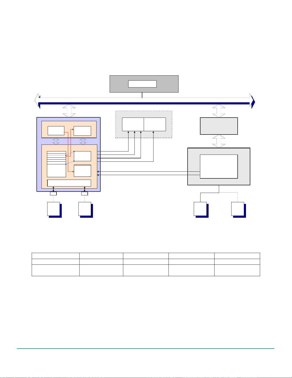
4.4. Legacy Support
Fixed I/O 60/64H access is
enabled by the
EmulationEnable (EE) bit
SMM
System BIOS
Fixed I/O 60/64H access can be disabled
or subtractive decode is used
P C I B U S
104H
108H
10CH
00H
100H
OHCI
Target Acce ss
Config Memory
Access
Memory map
LegacySupport
...
LegacyEnable
Opera tiona l
Registers
USB
Keyboard
IOEnb
MemEnb
RootHub
Fixed I/O 60H
and 64H Access
IO map (60H and 64H)
Legacy Support
Emulation Reg
Legacy
Emulati on
Handler
USB
Mouse
IRQ1
IRQ12
SMI#
A20OUT
KBIRQ1
MUIRQ12
System Chipset
System Int errupt
Controller
System Memory
Controller
Legacy Mouse and
Keyboard Controller
Legacy
Keybo ard
PCI Bridge...
80c42
System Chipset
Legacy
Mous e
Figure 4-2: Block Diagram of Legacy Signal Connection and Testing
Figure 4-2 shows the necessary connections for testing the legacy support functionality. The necessary signals must
be accessible on the motherboard used for legacy testing.
Testing R22 R23 R2 R3
Legacy support —
Default setting
[1]
—
[1]
10 k 10 k
0 0 10 k 10 k
(No legacy support)
[1] When testing the legacy support, resistors R22 and R23 (or the pull-down resistors located at the bottom of the evaluation
board) must be removed.
The JP2 connector is used for testing the keyboard and mouse legacy support.
UM10005_3 © Koninklijke Philips Electronics N.V. 2003. All rights reserved.
User’s Guide Rev. 2.0—April 2003 7 of 20
Page 8

Philips Semiconductors ISP1561 Evaluation Board User’s Guide
Pin Number Signal
1 GND
2 GND
3 A20OUT
4 SMI#
5 KBIRQ1
6 IRQ12
7 MUIRQ12
8 IRQ1
4.5. Input Clock
You can use either the 12 MHz crystal or the 48 MHz oscillator for the input clock. If the 12 MHz crystal is used,
both the resistors (R1 and R27) are soldered. If the 48 MHz oscillator is used, resistor R27 (0 ) must be
removed and pin 1 is pulled HIGH by R1. By default, the 12 MHz solution is implemented on the evaluation board.
4.6. External 5 V Power Source and S3 Wake-Up Capability
The jack J1 is used for connection of an external +5 V standby power supply to test the system wake-up from
S3cold and maintain the connected USB devices powered so that re-enumeration is avoided.
When the system is in the S3cold Power Management State, the +5 V main power at PCI connectors disappears.
Therefore, all downstream ports will not be powered because V
is derived from the PCI +5 V power supply. In
BUS
this situation, downstream bus-powered devices, such as mouse and keyboard, are not functional and cannot wake
up the system.
If you want to use the external +5 V supply, pads A and C on the evaluation board must be soldered together as
represented in the evaluation board drawing. Similarly, if you only intend to use PCI +5 V as the V
power source
BUS
(no testing of the system wake-up from S3cold and no external +5 V connected), then pads B and C must be
soldered together. Pads A, B and C are copper areas on the upper-right corner of the evaluation board (see Figure
4-1). This solution, using three copper pads, was adopted to avoid using a jumper because only the default
configuration (pads B and C connected together) will be used most of the time.
4.7. Loading the Subsystem ID and Vendor ID from the External EEPROM
Expansion board vendors can use the Subsystem Vendor ID and the Subsystem ID for identification of the board
and loading of the correct drivers by the operating system. The PCI SIG assigns the Subsystem Vendor ID and the
vendor determines the Subsystem ID.
The Subsystem Vendor ID and the Subsystem ID can be optionally loaded at power-on from the external serial
2
C-bus® EEPROM present on the ISP1561 evaluation board. A 3.3 V serial EEPROM of any size can be used
I
because only a few locations will be used for data loading.
2
The serial I
preprogrammed by using a standard serial EEPROM programmer. A socket is provided on the ISP1561 evaluation
board for repetitive reprogramming of the EEPROM.
An example on the I
Subsystem Vendor ID is 1132H, the Subsystem Device ID for OHCI is 1664H, and the Subsystem Device ID for
EHCI is 1665H.
C-bus EEPROM present on the ISP1561 evaluation board cannot be programmed onboard. It should be
2
C-bus EEPROM programming is given in Figure 4-3. In the example, it is assumed that the
UM10005_3 © Koninklijke Philips Electronics N.V. 2003. All rights reserved.
User’s Guide Rev. 2.0—April 2003 8 of 20
Page 9

Philips Semiconductors ISP1561 Evaluation Board User’s Guide
Address
0
1
2
3
4
5
6
7
[1] Loads Subsystem Vendor ID and Device ID. For more details, refer to the ISP1561 Hi-Speed USB PCI host controller
datasheet
.
2
C-Bus EEPROM Content
I
32H
11H
64H
16H
65H
16H
FFH
[1]
15H
Figure 4-3: I
2
C-bus EEPROM Programming Example
Subsystem Vendor ID—LOW
Subsystem Vendor ID—HIGH
Subsystem Device ID (OHCI)—LOW
Subsystem Device ID (OHCI)—HIGH
Subsystem Device ID (EHCI)—LOW
Subsystem Device ID (EHCI)—HIGH
reserved
reserved
Note: Do not load any other values in reserved fields, otherwise, functionality of the ISP1561 is not guaranteed.
5. Hi-Speed USB (EHCI) Drivers
For Windows 2000 and Windows XP, the standard Microsoft EHCI drivers can be used. The best way to obtain
the latest EHCI drivers is to download from the Microsoft web site. Installation or update of EHCI device drivers
for the supported operating systems follows the standard installation procedure for device drivers, and so should
not present any difficulty.
However, the usb2.inf file must be modified to match the Philips Vendor ID (VID), Device ID (DID) and IC
revision code.
If there are difficulties in loading the Hi-Speed USB (EHCI) drivers, particularly for Windows 2000 and Windows
XP, the first step is to check the correctness of the VID, DID and REV_ID specified in the INF file. These values
must match with the values implemented in the respective revision of the ISP1561 found on the evaluation board.
An example of the necessary modifications that must be made to a usb2.inf file is as follows. The file example
contains information regarding the ISP1561 VID, DID and REV_ID. These modifications are similar for Windows
2000 and Windows XP.
1. Add the following line of code under the [Manufacturer] section:
%Philips%=Philips
2. Under the USB 2.0 Hub Support section, add the following lines of code:
; =================== Philips ==================================
[Philips]
; for Windows 2000
%PCI\VEN_1131&DEV_1562&REV_30.DeviceDesc%=EHCI,PCI\VEN_1131&DEV_1562&REV_30
%USB\ROOT_HUB20.DeviceDesc%=ROOTHUB2,USB\ROOT_HUB20
; HUBs
%USB\HubClass.DeviceDesc%=Usb2Hub.Dev,USB\HubClass
3. Add the following lines of code under the [Strings] section:
Philips="Philips"
PCI\VEN_1131&DEV_1562&REV_30.DeviceDesc="PHILIPS PCI to USB Enhanced Host Controller ES5"
For Windows 98 and Windows Me, Philips provides EHCI device drivers; no modification in its INF file is required.
Windows 98, Windows Me, Windows 2000 and Windows XP supply the device drivers for OHCI by default.
UM10005_3 © Koninklijke Philips Electronics N.V. 2003. All rights reserved.
User’s Guide Rev. 2.0—April 2003 9 of 20
Page 10

Philips Semiconductors ISP1561 Evaluation Board User’s Guide
6. Loading of the ISP1561 Drivers
This section provides an example on loading device drivers after an ISP1561 add-on card is plugged into a
computer running Windows 98. Loading of OHCI drivers (supplied by the operating system) and Hi-Speed USB
(EHCI) drivers provided by Philips is shown in a step-by-step process.
Note: In the case of Windows 2000 and Windows XP, OHCI drivers are automatically installed by the operating
system without any user intervention.
6.1. Loading of OHCI Drivers
The following wizard appears when an ISP1561 add-in card is plugged on a computer running Windows 98,
enabling you to install OHCI drivers.
UM10005_3 © Koninklijke Philips Electronics N.V. 2003. All rights reserved.
User’s Guide Rev. 2.0—April 2003 10 of 20
Page 11

Philips Semiconductors ISP1561 Evaluation Board User’s Guide
UM10005_3 © Koninklijke Philips Electronics N.V. 2003. All rights reserved.
User’s Guide Rev. 2.0—April 2003 11 of 20
Page 12

Philips Semiconductors ISP1561 Evaluation Board User’s Guide
Click the Browse button and locate the path where the Windows 98 kit is installed.
Note: The preceding steps will be repeated twice for loading of the drivers for the two OHCI (OHCI1 and
OHCI2).
UM10005_3 © Koninklijke Philips Electronics N.V. 2003. All rights reserved.
User’s Guide Rev. 2.0—April 2003 12 of 20
Page 13

Philips Semiconductors ISP1561 Evaluation Board User’s Guide
6.2. Loading of EHCI Drivers
After the drivers have been loaded for OHCI1 and OHCI2, the following wizard appears, when an ISP1561 add-on
card is plugged on to a computer running Windows 98, enabling you to install the Hi-Speed USB EHCI drivers.
UM10005_3 © Koninklijke Philips Electronics N.V. 2003. All rights reserved.
User’s Guide Rev. 2.0—April 2003 13 of 20
Page 14

Philips Semiconductors ISP1561 Evaluation Board User’s Guide
UM10005_3 © Koninklijke Philips Electronics N.V. 2003. All rights reserved.
User’s Guide Rev. 2.0—April 2003 14 of 20
Page 15

Philips Semiconductors ISP1561 Evaluation Board User’s Guide
For your reference, the contents of the Windows 98/Windows Me EHCI driver are as follows:
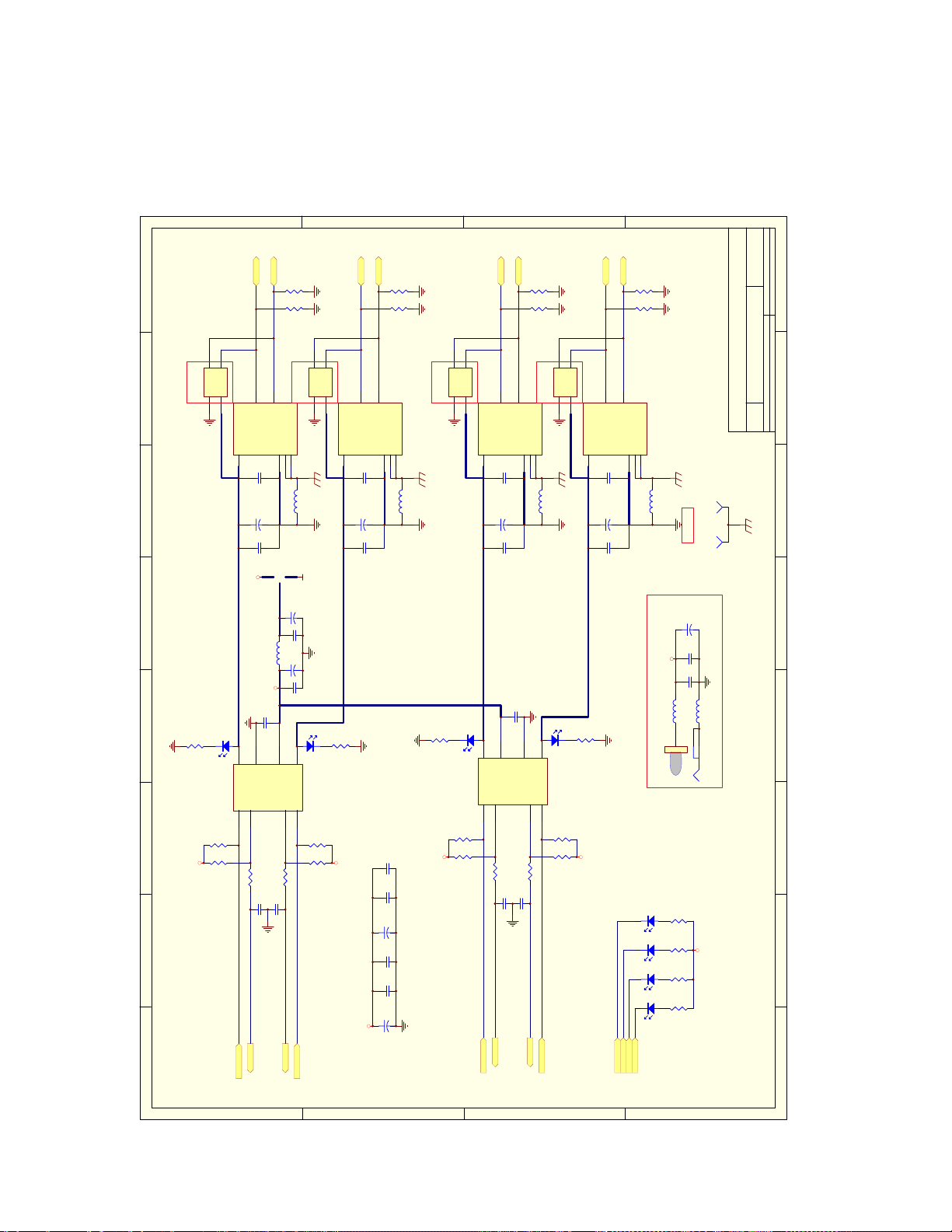
7. Schematics
UM10005_3 © Koninklijke Philips Electronics N.V. 2003. All rights reserved.
User’s Guide Rev. 2.0—April 2003 15 of 20
Page 16

Number RevisionSize
A3
Date: 6-Mar-2003 Sheet of
File: C:\1561Asic\Ver4-ES5\isp1561_ES5.DDBDrawn By:
1 2 3 4 5 6 78
REF_GND
RREF
B
0.1uF
C26
1 2
3 4
5 6
7 8
JP2
C63
2.2uF/10V
+
R25
0R
OSC2
114
OSC1
12MHz
C2 22pF
12K/1%
87
XIN
AD31
C/BE0#
C/BE1#
C/BE2#
C/BE3#
AD[31..0]
R3
48MHZ
78
R2
DVAUX
R28
33R
C1 22pF
88
XOUT
INTA#
REQ#
GNT#
IDSEL
FRAME#
IRDY#
TRDY#
REQ#
GNT#
IDSEL
INTA#
IRDY#
FRAME#
C/BE[3..0]#
HEADER 4X2
R23
A20OUT
11
A20OUT
PERR#
1K
PERR#
0R
R22
0R
KBIRQ1
MUIRQ12
SMI#
15
12
13
SMI#
KBIRQ1
MUIRQ12
4
SERR#
PAR
RST#
PCICLK
PME#
R26
0R
PAR
RST#
PME#
SERR#
PCICLK
10K
10K
IRQ1
IRQ12
7
8
IRQ1
IRQ12
DEVSEL#
STOP#
R21
STOP#
TRDY#
DEVSEL#
A
Title
0.1uF
C30
PLL_VAUX
R20
1K
9
ISP1561
SEL2PORTS
GND_RREF
FB4
BLM18PG121SN1
94
AGND
124
AGND
118
AGND
111
AGND
104
DGND
128
DGND
86
DGND
83
DGND
76
DGND
69
DGND
61
DGND
53
DGND
45
DGND
37
DGND
29
DGND
21
DGND
14
DGND
6
C8
0.001uF
AVAUX
0.1uF
C28
0.001uF
C9
0.1uF
C29
C7
0.001uF
C22
0.1uF
C18
0.1uF
C21
0.1uF
C20
0.1uF
C19
0.1uF
+3.3V DVAUXC3
C6
0.001uF
C5
0.001uF
0.001uF
C4
0.001uF
D
C64
2.2uF/6.3V
4.7uF/6.3V
0.01uF
100pF
0.1uF
+
C60
0.01uF
C48
100pF
LINK1
LINK2
LINK3
PLL_VAUX
C27
0.1uF
FB3
BLM18PG121SN1
DVAUX
330R
C56
47uF/6.3V
+
C62
470pF
DVAUX
C24
0.1uF
PLL_VAUX AVAUX
123
+3.3V
HEADER 3
DVAUX
LINK4
DVAUX
R45
LINK1
LINK2
LINK3
LINK4
113
126
112
125
U2
AMB192AMB299AMB3
AMB4
GLNK191GLNK298GLNK3
GLNK4
AVAUX
121
AVAUX
115
AVAUX
108
AVAUX
93
VAUX
85
VAUX
5
AVAUX_PLL
101
VDD
80
VDD
73
VDD
65
VDD
57
VDD
49
VDD
41
VDD
33
VDD
25
VDD
17
VDD
10
48MSel1SCL2SDA3AD084AD182AD281AD379AD478AD577AD675AD774AD871AD970AD1068AD1167AD1266AD1364AD1463AD1562AD1646AD1744AD1843AD1942AD2040AD2139AD2238AD2336AD2432AD2531AD2630AD2728AD2827AD2926AD3024AD3123C/BE0#72C/BE1#60C/BE2#47C/BE3#34INTA#16REQ#22GNT#20IDSEL35FRAME#48IRDY#50TRDY#51DEVSEL#52STOP#54CLKRUN#55PERR#56SERR#58PAR59RST#18PCICLK19PME#
AD0
AD1
AD2
SEL48M
SCL
SDA
R1
10K
R27
0R
8
C65
+
7654321
C59
C47
C23
FB1
BLM18PG121SN1
DVAUX AVAUX
R19
D1 LED
DVAUX
+3.3VAux
JP1
C
DP1
DP2
DP3
DP4
DM1
DM2
DM3
OC1#
OC2#
OC3#
OC4#
PWE1#
51K
Must be soldered for S3 support.
OC1#
OC2#
OC3#
OC4#
PWE1#
105
119
100
114
127
OC1#89OC2#96OC3#
OC4#
GRN195GRN2
GRN3
GRN4
PWE1#90PWE2#97PWE3#
AD3
AD4
AD5
AD6
AD7
AD8
AD9
AD10
AD11
AD12
AD13
AD14
R16
4K7
R15
4K7
C25
0.1uF
+3.3V DVAUX
8
Vcc
A01A12A33GND
U1
DM4
PWE2#
PWE3#
PWE4#
+5Volt
*pin94
PWE2#
PWE3#
PWE4#
DM1
DM2
DM3
106
120
102
109
116
DM1
DM2
DM3
PWE4#
AD15
AD16
AD17
AD18
AD19
AD21
AD20
R24
0R
6
7
SCL
NC/WP
R18
DM4
DP1
DP2
DP3
DP4
107
103
110
117
123
122
DP1
DP2
DP3
DP4
DM4
AD22
AD23
AD24
AD25
AD26
AD27
AD28
AD29
AD30
5
SDA
AT24C01A-2.7
4
D
C
B
A
Page 17

D
8
C
B
A
+5V
7654321
AD0
AD2
AD4
AD6
AD9
INTA#
INTA#
A2
A7
A5
A8
A1
A6
A3
A4
TDI
+5V
TMS
+12V
INTC
INTA
TRST
-12VB1TCKB2GNDB3TDOB4+5VB5+5VB6INTBB7INTDB8PRSNT1B9RESERVED
CON1
RST#
AD26
AD28
AD30
PME#
GNT#
3.3VAux
AD26
AD28
AD30
PME#
GNT#
RST#
3.3VAux
A9
A11
A14
A15
A20
A22
A23
A17
A21
A10
VIO
+5V
RESERVED
B10
A19
A16
A18
A24
3V3
VIO
RST
GNT
PME
GND
GND
AD30
AD28
3V3_AUX
RESERVED
PRSNT2
RESERVED
B11
B14
B15
AD26
GND
CLK
GND
REQ
VIO
AD31
AD29
GND
AD27
AD25
B16
B17
B18
B19
B20
B21
B22
B23
B24
AD16
AD18
AD20
AD22
AD24
IDSEL
IDSEL
AD24
A25
A26
AD24
IDSEL
3V3
C/BE3
B25
B26
FRAME#
FRAME#
AD16
AD18
AD20
AD22
A34
A28
A29
A31
A32
A27
A33
A30
A35
3V3
3V3
GND
AD22
AD20
AD18
AD16
FRAME
AD23
GND
AD21
AD19
3V3
AD17
C/BE2
GND
B27
B28
B29
B30
B31
B32
B33
B34
B35
PAR
AD11
AD13
AD15
STOP#
TRDY#
PAR
AD15
STOP#
TRDY#
A40
A41
A36
A38
A44
A43
A39
A37
A42
3V3
PAR
GND
GND
GND
STOP
TRDY
RESERVED
RESERVED
IRDY
3V3
DEVSEL
GND
LOCK
PERR
3V3
SERR
3V3
B36
B37
B38
B39
B40
B41
B42
B43
B44
AD15
C/BE1
C/BE0#
AD13
AD11
AD9
C/BE0#
AD6
AD4
AD2
AD0
C66
47uF/10V
+
A60
A61
A52
A46
A47
A49
A45
A53
A48
3V3
3V3
AD9
GND
AD13
AD11
C/BE0
AD14
GND
AD12
AD10
M66EN
AD8
AD7
B45
B46
B47
B48
B49
B52
B53
A62
A54
A55
A57
A58
A59
A56
VIO
+5V
+5V
AD6
AD4
AD2
AD0
GND
REQ64
3V3
AD5
AD3
GND
AD1
VIO
ACK64
+5V
+5V
PCIBUS
B54
B55
B56
B57
B58
B59
B60
B61
B62
+3.3V
Number RevisionSize
A3
Title
Date: 17-Feb-2003 Sheet of
File: C:\1561Asic\Ver4-ES5\pci_conn.DDB Drawn By:
C58
47uF/6.3V
+
C57
47uF/6.3V
+
C33
0.1uF
C49
100pF
C31
0.1uF
C32
0.1uF
C10
0.001uF
C11
0.001uF
PCICLK
REQ#
AD31
AD29
AD27
AD25
C/BE3#
AD23
AD21
AD19
AD17
C/BE2#
IRDY#
DEVSEL#
PERR#
SERR#
C/BE1#
AD14
AD12
AD10
AD8
AD7
AD5
AD3
AD1
AD8
AD7
AD5
AD3
AD31
AD29
AD27
AD25
AD23
AD21
AD19
REQ#
PCICLK
D
C
AD17
C/BE3#
IRDY#
C/BE2#
DEVSEL#
PERR#
AD14
AD12
AD10
SERR#
C/BE1#
B
AD1
1 2 3 4 5 6 78
A
Page 18
D
C
B
A
DP1
3
L1
L2
GND
Vcc
4
D4
LED
R5
10K
R4
10K
DM1
DM1
2
ESD
D-
VBUS1GND4SHIELD5SHIELD
C12
0.001uF
C72
220uF/10V
+
C40
0.1uF
ACB
5V_Standby
C39
5
6
GND
OUTB
FLGB#3ENB#
U3
4
R6
10K
C35
0.1uF
PWE1#
OC1#
OC1#
PWE1#
R38
15K
DP1
R37
15K
2
3
L1
L2
GND
3
D+
FB7
+5Volt
0.1uF
7
C36
Vcc
ESD4
Optional
1
4
CON2
USB 1
6
FB10
BLM18PG121SN1
+5V
C75
22uF/10V
+
C17
0.001uF
C69
47uF/10V
BLM41PG600SN1
+
C61
0.01uF
D5
LED
8
IN
OUTA
ENA#1FLGA#
MIC2526
2
R9
10K
R8
10K
R7
10K
0.1uF
OC2#
PWE2#
OC2#
PWE2#
8
2
7654321
ESD3
Optional
1
R29
560R
+5Volt
DM2
DM2
2
ESD
D-
VBUS1GND4SHIELD5SHIELD
C13
0.001uF
C73
220uF/10V
+
C41
0.1uF
R30
560R
+5Volt
+5Volt
DP2
R40
15K
DP2
R39
15K
2
3
L1
L2
GND
3
D+
CON3
USB 2
6
FB8
BLM18PG121SN1
C55
100pF
C46
0.1uF
C68
47uF/10V
+
C54
100pF
C45
0.1uF
C67
47uF/10V
+
Vcc
ESD2
Optional
1
4
D2
LED
R31
560R
R11
10K
R10
10K
+5Volt
DM3
DM3
2
ESD
D-
VBUS1GND4SHIELD5SHIELD
C50
100pF
C70
220uF/10V
+
C42
0.1uF
8
7
IN
OUTA
ENA#1FLGA#
U4
2
R12
10K
C37
0.1uF
PWE3#
OC3#
OC3#
PWE3#
DP3
R42
15K
DP3
R41
15K
2
3
L1
L2
GND
3
D+
C34
0.1uF
6
C38
Vcc
ESD1
Optional
1
4
CON4
USB 3
6
FB2
BLM18PG121SN1
D3
LED
5
GND
OUTB
FLGB#3ENB#
MIC2526
4
R14
10K
R17
10K
R13
10K
0.1uF
OC4#
PWE4#
OC4#
PWE4#
DM4
DM4
2
ESD
D-
VBUS1GND4SHIELD5SHIELD
C51
100pF
C71
220uF/10V
+
C43
0.1uF
R32
560R
+5Volt
LINK4
DP4
R44
15K
DP4
R43
15K
3
D+
CON5
USB 4
6
FB9
BLM18PG121SN1
Bracket holes
C74
100uF/10V
+
C16
0.001uF
+5V_Standby
C44
0.1uF
FB5
BLM31PG121SN1
123
J1
Optional
D9
LED
R36
560R
D8
LED
R35
560R
D7
LED
R34
560R
D6
LED
R33
560R
LINK3
LINK2
LINK1
LINK1
LINK2
LINK3
LINK4
Number RevisionSize
A3
Title
Date: 17-Feb-2003 Sheet of
File: C:\1561Asic\Ver4-ES5\power_switch.DDBDrawn By:
SW2
SOCKET
SW1
SOCKET
FB6
BLM31PG121SN1
JACK
+5Volt
1 2 3 4 5 6 78
D
C
B
A
Page 19

Philips Semiconductors ISP1561 Evaluation Board User’s Guide
8. Bill of Materials
The following table provides the bill of materials for the ISP1561 evaluation board.
Quantity Part Type Designator Footprint Description
2 — JP3 JP4 RADO.2 —
13 0.001 µF C3 C4 C5 C6 C7 C8 C9 C10 C11
C12 C13 C16 C17
3 0.01 µF C59 C60 C61 0603 —
29 0.1 µF C18 C19 C20 C21 C22 C23 C24
C25 C26 C27 C28 C29 C30 C31
C32 C33 C34 C35 C36 C37 C38
C39 C40 C41 C42 C43 C44 C45
C46
6
0
R22 R23 R24 R25 R26 R27 0603 —
7 100 pF C47 C48 C49 C50 C51 C54 C55 0603 —
1 100 µF/10 V C74 REC1/2 —
14
10 k
R1 R2 R3 R4 R5 R6 R7 R8 R9 R10
R11 R12 R13 R14
1
12 k ±1%
R18 0603 —
1 12 MHz OSC1 XTAL1 30 ppm
8
2
15 k
1 k
R37 R38 R39 R40 R41 R42 R43 R44 0603 —
R20 R21 0603 —
1 2.2 µF /10 V C63 — —
1 2.2 µF /6.3 V C64 — —
4 220 µF/10 V C70 C71 C72 C73 REC1/2 —
2 22 pF C1 C2 0603 —
1 22 µF/10 V C75 REC1/2 —
1
1
330
33
R19 0603 —
R28 — —
1 4.7 µF/6.3 V C65 — —
1 470 pF C62 0603 —
4 47 µF/10 V C66 C67 C68 C69 CASE-D —
3 47 µF /6.3 V C56 C57 C58 CASE-D —
1 48 MHz OSC2 XTAL3 30 to 50 ppm, optional
3
8
1
4 k
560
51 k
R15 R16 R17 0603 —
R29 R30 R31 R32 R33 R34 R35 R36 0603 optional
R45 0603 optional
1 AT24C01A-2.7 U1 — Atmel I2C-bus
7 BLM18PG121SN1 FB1 FB2 FB3 FB4 FB8 FB9 FB10 — Murata
2 BLM31PG121SN1 FB5 FB6 1206 Murata; optional
1 BLM41PG600SN1 FB7 1206Cust Murata; optional
4 ESD ESD1 ESD2 ESD3 ESD4 — PSR05-PD10611-
1 HEADER 3 JP1 SIP3 Optional
1 HEADER 4X2 JP2 — Optional
1 ISP1561 U2 — Philips
1 JACK J1 — PCB mount socket pin
9 LED D1 D2 D3 D4 D5 D6 D7 D8 D9 LED3 Optional
0603 —
0603 —
0603 —
EEPROM; optional
Protek devices;
optional
diameter 2.5; optional
UM10005_3 © Koninklijke Philips Electronics N.V. 2003. All rights reserved.
User’s Guide Rev. 2.0—April 2003 19 of 20
Page 20

Philips Semiconductors ISP1561 Evaluation Board User’s Guide
Quantity Part Type Designator Footprint Description
2 MIC2526 U3 U4 SO-8 Micrel
1 USB 1 CON2 USB-TYPEA —
1 USB 2 CON3 USB-TYPEA —
1 USB 3 CON4 USB-TYPEA —
1 USB 4 CON5 USB-TYPEA —
9. References
• ISP1561 Hi-Speed USB PCI host controller datasheet
• Designing a USB 2.0 Host PCI Adapter Using ISP1561 application note
• Universal Serial Bus System Architecture, First and Second Editions from MindShare
• Universal Serial Bus Specification Rev. 1.1
• Universal Serial Bus Specification Rev. 2.0
• PCI Local Bus Specification, Rev. 2.2
• PCI Bus Power Management Interface Specification, Rev. 1.1
• PCI System Architecture, Fourth Edition from MindShare.
UM10005_3 © Koninklijke Philips Electronics N.V. 2003. All rights reserved.
User’s Guide Rev. 2.0—April 2003 20 of 20
Page 21

Philips Semiconductors
Philips Semiconductors is a worldwide company with over 100 sales
offices in more than 50 countries. For a complete up-to-date list of our
sales offices please e-mail
sales.addresses@www.semiconductors.philips.com.
A complete list will be sent to you automatically.
You can also visit our website
http://www.semiconductors.philips.com/sales/
www.semiconductors.philips.com
© Koninklijke Philips Electronics N.V. 2003
All rights reserved. Reproduction in whole or in part is prohibited
without the prior written consent of the copyright owner. The information presented in this document does not form part of any quotation or contract, is believed to be accurate and reliable and may be
changed without notice. No liability will be accepted by the publisher
for any consequence of its use. Publication thereof does not convey
or imply any license under patent – or other industrial or intellectual
property rights.
 Loading...