

Page 1

UM10014_4
Semiconductors
ISP1520 Hi-Speed USB Hub Demo Board
Rev. 04.00 — 11 May 2004 User manual
Document information
Info Content
Keywords
Abstract
ISP1520, hub controller, USB, universal serial bus
This document describes the ISP1520 hub demo board. It also contains
the related schematics, the PCB layout, and the Bill of Material
.
Page 2

Philips Semiconductors
Revision history
Rev Date Description
4.0 May 11, 2004 Updated the schematic.
3.0 April 14, 2004 Updated the following:
• Section 2
• Section 4
• Section 5.5
• Section 6
1.1 Feb 2003 Updated Section 5.5 and Section 6.
1.0 Nov. 2002 First release.
ISP1520 Hi-Speed USB Hub Demo Board
Contact information
For additional information, please visit: http://www.semiconductors.philips.com/
UM10014_4
For sales office addresses, please send an email to: sales.addresses@www.semiconductors.philips.com
User manual Rev. 04.00 — 11 May 2004 2 of 18
© Koninklijke Philips Electronics N.V. 2004. All rights reserved.
Page 3

Philips Semiconductors
This is a legal agreement between you (either an individual or an entity) and Philips Semiconductors. By accepting
this product, you indicate your agreement to the disclaimer specified as follows:
ISP1520 Hi-Speed USB Hub Demo Board
UM10014_4
DISCLAIMER
PRODUCT IS DEEMED ACCEPTED BY RECIPIENT. THE PRODUCT IS PROVIDED “AS IS” WITHOUT
WARRANTY OF ANY KIND. TO THE MAXIMUM EXTENT PERMITTED BY APPLICABLE LAW, PHILIPS
SEMICONDUCTORS FURTHER DISCLAIMS ALL WARRANTIES, INCLUDING WITHOUT LIMITATION ANY
IMPLIED WARRANTIES OF MERCHANT ABILITY, FITNESS FOR A PARTICULAR PURPOSE, AND
NONINFRINGEMENT. THE ENTIRE RISK ARISING OUT OF THE USE OR PERFORMANCE OF THE
PRODUCT AND DOCUMENTATION REMAINS WITH THE RECIPIENT. TO THE MAXIMUM EXTENT
PERMITTED BY APPLICABLE LAW, IN NO EVENT SHALL PHILIPS SEMICONDUCTORS OR ITS SUPPLIERS BE
LIABLE FOR ANY CONSEQUENTIAL, INCIDENTAL, DIRECT, INDIRECT, SPECIAL, PUNITIVE, OR OTHER
DAMAGES WHATSOEVER (INCLUDING, WITHOUT LIMITATION, DAMAGES FOR LOSS OF BUSINESS
PROFITS, BUSINESS INTERRUPTION, LOSS OF BUSINESS INFORMATION, OR OTHER PECUNIARY LOSS)
ARISING OUT OF THIS AGREEMENT OR THE USE OF OR INABILITY TO USE THE PRODUCT, EVEN IF
PHILIPS SEMICONDUCTORS HAS BEEN ADVISED OF THE POSSIBILITY OF SUCH DAMAGES.
User manual Rev. 04.00 — 11 May 2004 3 of 18
© Koninklijke Philips Electronics N.V. 2004. All rights reserved.
Page 4

Philips Semiconductors
ISP1520 Hi-Speed USB Hub Demo Board
UM10014_4
Contents
1. Introduction...............................................................................................................................................................................5
2. ISP1520 Hub demo board Features......................................................................................................................................5
3. System Requirements...............................................................................................................................................................6
4. Power Supply Adapter Requirements..................................................................................................................................6
5. Hub demo board Description................................................................................................................................................6
5.1. ISP1520 64-Pin TQFP Package......................................................................................................................................6
5.2. GoodLink Indicator.........................................................................................................................................................7
5.3. Port Power Switch Transistors.....................................................................................................................................7
5.4. Overcurrent Circuit Detection....................................................................................................................................7
5.5. Power Supply....................................................................................................................................................................8
5.6. I2C-Bus Interface..............................................................................................................................................................9
6. Schematics................................................................................................................................................................................10
7. Installing the Board.................................................................................................................................................................17
8. Bill of Materials for the ISP1520 Hub demo board..........................................................................................................18
9. References................................................................................................................................................................................18
GoodLink and I
2
C-Bus are trademarks of Koninklijke Philips Electronics N.V. Microsoft is a registered trademark of
Microsoft Corp. The names of actual companies and products mentioned herein may b e the trademarks of their
respective owners. All other names, products, and trademarks are the property of their respectiv e owners.
User manual Rev. 04.00 — 11 May 2004 4 of 18
© Koninklijke Philips Electronics N.V. 2004. All rights reserved.
Page 5
Philips Semiconductors
1. Introduction
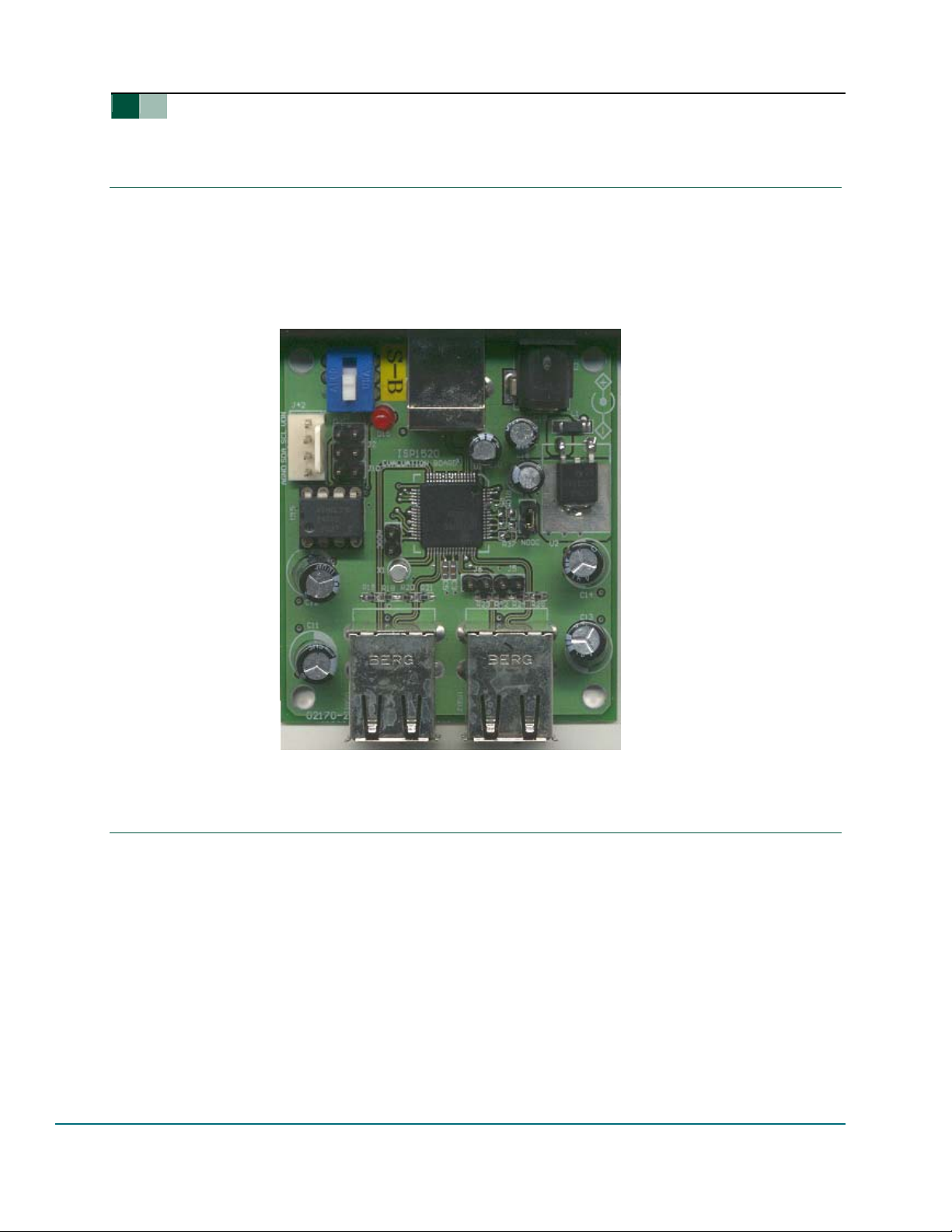
The ISP1520 is a Hi-Speed Universal Serial Bus (USB) hub IC, with four downstream facing ports.
The ISP1520 Hub demo board is designed to demonstrate the features and functionality of the
ISP1520. This version is targeted at low-cost designs. Nevertheless, it still contains a large
number of features and options to be evaluated.
This document describes the ISP1520 hub demo board. It also contains the related schematics,
the PCB layout, and the Bill of Material (BoM).
UM10014_4
ISP1520 Hi-Speed USB Hub Demo Board
Figure 1-1: ISP1520 Hub demo board
2. ISP1520 Hub demo board Features
• Complies with Universal Serial Bus Specification Rev. 2.0
• Supports self-powered operation
• Configurable number of downstream facing ports (from two to four)
• Customizable Vendor ID, Product ID and Serial Number (by using an external EEPROM or
an external microcontroller)
• Individual power switching and individual overcurrent protection
TM
• USB traffic indication (GoodLink
User manual Rev. 04.00 — 11 May 2004 5 of 18
LED) on the upstream facing port
© Koninklijke Philips Electronics N.V. 2004. All rights reserved.
Page 6

Philips Semiconductors
3. System Requirements
This hub can be attached to a computer that has a USB or Hi-Speed USB host installed, and
running any of these operating systems:
®
• Windows
98
• Windows Me
• Windows 2000
• Windows XP
®
• MacOS
If this hub is plugged into a USB host controller, it will only work as a full-speed hub.
4. Power Supply Adapter Requirements
Regulated Output: 5.1VCC ± 5%, 2.5A.
Warning: If you are using the board version 02170-2, make sure that the power plug polarity is
(+) at the core and (-) at the outer shield.
UM10014_4
ISP1520 Hi-Speed USB Hub Demo Board
5. Hub demo board Description
5.1. ISP1520 64-Pin TQFP Package
The ISP1520 has the following port configurations:
• One Hi-Speed USB and Original USB capable upstream facing port (USB0), and
• Four Hi-Speed USB and Original USB capable downstream facing ports (USB1, USB2, USB3,
USB4).
The downstream facing ports USB3 and USB4 can be disabled. By design, ports USB1 and USB2
cannot be disabled.
Table 5-1 shows the jumper setting versus port activation.
Table 5-1: Jumper Setting vs. Port Activation
J6, J5 Active Ports
OFF, OFF 1, 2, 3, 4*
ON, ON 1, 2
*—Default settings.
User manual Rev. 04.00 — 11 May 2004 6 of 18
© Koninklijke Philips Electronics N.V. 2004. All rights reserved.
Page 7

Philips Semiconductors
5.2. GoodLink Indicator
A Philips GoodLink LED D15 (red) is located near the upstream facing port. This LED bl inks on
every successful USB transaction.
UM10014_4
ISP1520 Hi-Speed USB Hub Demo Board
5.3. Port Power Switch Transistors
The hub switches the bus power of each downstream facing port through a low ohmic PMOS
transistor.
5.4. Overcurrent Circuit Detection
The integrated analog overcurrent detection circuit of the ISP1520 senses the voltage drop
across the power switch. When the port draws too much current, the voltage drop across the
power switch exceeds the trip voltage threshold. The overcurrent circuit detects this and
automatically switches off the power switch. More information on choosing the switch and
trimming the overcurrent detection voltage can be found in the ISP1520 Hi-Speed Universal Serial
Bus hub controller data sheet.
User manual Rev. 04.00 — 11 May 2004 7 of 18
© Koninklijke Philips Electronics N.V. 2004. All rights reserved.
Page 8

Philips Semiconductors
The hub demo board also contains an option to disable th e overcurrent detection. This can be
done in two stages. First place the NOOC jumper in the appropriate position to set the hub’s
descriptor (see Table 5-2).
Table 5-2: Overcurrent Detection Selection Using NOOC
NOOC Overcurrent Detection Logic State
ON YES 0 (LOW)
OFF NO 1 (HIGH)
UM10014_4
ISP1520 Hi-Speed USB Hub Demo Board
Then, desolder R28, R29, R30 and R31, and solder R32, R33, R34 and R36 on the PCB (see
schematics).
As a lower cost alternative, there are provisions on the board to use polyswitches to handle
overcurrent conditions. In this case the port switching transistors are bypassed. If this solution is
preferred, then the overcurrent detection circuit inside the chip must be switched to the digital
mode
Table 5-3: Mode Selection Using ADOC
ADOC Mode Logic State
ON Digital 0 (LOW)
OFF Analog* 1 (HIGH)
*—
Default
settings.
5.5. Power Supply
This hub demo board can be used as a self-powered USB hub. When used as a self-powered hub,
use the provided power supply.
The SW1 switch sets the powering mode in the hub’s descriptors; see Table 5-4.
User manual Rev. 04.00 — 11 May 2004 8 of 18
© Koninklijke Philips Electronics N.V. 2004. All rights reserved.
Page 9

Philips Semiconductors
Table 5-4: Power Mode Selection Using SW1
ISP1520 Hi-Speed USB Hub Demo Board
SW1 Power Mode
S
B
Self-powered*
Ignore
UM10014_4
*—
Default
settings.
Figure 5-1: Windows Reporting of the Self-Powered Mode
5.6. I2C-Bus Interface
The ISP1520 can use either its USB descriptors from the internal ROM, or from an external I2C-
TM
EEPROM or microcontroller. Mode selection is done through jumpers J1and J2 (see Table
bus
5-5:).
Table 5-5: Mode Selection Using J1 and I2
J1 J2 Mode SCL SDA
ON ON
OFF OFF
*—Default settings.
User manual Rev. 04.00 — 11 May 2004 9 of 18
Internal ROM LOW LOW
2
I
C-bus EEPROM* HIGH HIGH
© Koninklijke Philips Electronics N.V. 2004. All rights reserved.
Page 10

Philips Semiconductors
UM10014_4
ISP1520 Hi-Speed USB Hub Demo Board
An external I
through the J42 connector.
The J10 jumper is connected to the “Write Protect” pin of the I
Controller and the EEPROM have different I
on-board, select the jumper according to Table 5-6. It is recommended that you program the
2
C-bus EEPROM before connecting the hub to USB through the USB host.
I
For convenience, the hub demo board is equipped with a socket for this compo nent, allowing
easy programming using a universal EPROM programmer as well.
Table 5-6: EEPROM Programming
6. Schematics
2
C-bus controller acting as a master can also be used to update hub descriptors
2
C-bus device addresses. To program this IC
J10 WP_N
ON Write enable
OFF Write protect
2
C-bus EEPROM. The Hub
User manual Rev. 04.00 — 11 May 2004 10 of 18
© Koninklijke Philips Electronics N.V. 2004. All rights reserved.
Page 11

1
2
3
4
5
6
7
8
VDN
R5
500K
A A
R105
NC
V3. 3REG
0. 1uFC1
0. 1uFC2
0. 1uFC3
V3.3R EG
0. 1uFC4
Qrp u NPN
R12
10K
100KR15
V3.3R EG
0. 1uFC5
SUSPEND
OC1
OC2
OC3
OC4
PSW1
PSW2
PSW3
PSW4
R13
NC
100KR37
NOOC
JUMPER
OC1
OC2
OC3
OC4
PSW1
PSW2
PSW3
PSW4
1K5, 5%
R10
12K, 1%
C6
0. 1uF
SP/BP
V3. 3REG
100KR14
ADOC
JUMPER
VBU S
RVbus
5K6
VDN
C20
0.1 uF
V3. 3REG
V3. 3REG
B B
C C
D D
OC pr otectio n : No JUM PER
No OC prot ecti on : JUMPER
1
8
TES T_HI GH
9
VCC1
13
VCC2
23
VCC3
38
TES T_HI GH
39
VCC1
45
VCC2
57
VCC3
11
VCC4
41
VCC4
24
VCC5
56
VCC5
19
OC1
29
OC2
27
OC3
25
OC4
20
PSW1
30
PSW2
28
PSW3
26
PSW4
5
RPU
7
R11
ADOC
RREF
Analog OC : No JUMPER
Digital OC : JUMPER
2
RESET31HP
17
NOOC
50
GRN 160GRN 254GRN 352GRN 4
SP/BP18SUSPEND1ADOC32NOOC
DGND21DGND22DGND58DGND59AGND2AGND6AGND10AGND14AGND35AGND40AGND42AGND
49
SP/BP
ADOC
0.1u FC7
A0
A1
A2
GND
AT24 C01
4
3
2
1
J42
SIP_4P
VCC
SCL
SDA
U15
WP
1
2
3
4
AM B161AM B255AM B353AM B4
VDN
R9
8
7
6
5
51
TES T_HI GH
VDN
62
330R
DM0
HUB GL
DM1
DM2
DM3
DM4
XTAL1
XTAL2
SDA
R35
NC
D15
RED
DP0
DP1
DP2
DP3
DP4
SCL
46
VBU S1
VBU S2
3
4
15
16
36
37
43
44
47
48
DM0
DP0
DM1
DP1
DM2
DP2
DM3
DP3
DM4
DP4
DM0
DP0
DM1
DP1
DM2
DP2
DM3
DP3
DM4
DP4
VBU S3
J5 & J6 : To disable port#3 & port#4
J6
J5
12
33
34
63
64
R16
R17
2K2
2K2
V3. 3REG
X1
12M Hz
VBU S4
C8
22pF
C9
22pF
ESD 1
REF11I/O1
4
I/O2
REF2
HEADE R 3
DM1
DP1
DM2
DP2
ESD 2
REF11I/O1
4
I/O2
REF2
HEADE R 3
ESD 3
REF11I/O1
4
I/O2
REF2
HEADE R 3
DM3
DP3
DM4
DP4
ESD 4
REF11I/O1
4
I/O2
REF2
HEADE R 3
USB0
CHASSIS
ESD 5
4
REF2
C10
1uF
REF11I/O1
HEADE R 3
VBU S
GND
USB_U P
1
VBU S
DM0
2
D-
DP0
3
D+
4
5
3
I/O2
2
15KR18
DM3
DP3
DM4
DP4
15KR19
A2
A3
B2
B3
15KR20
15KR21
15KR22
15KR23
15KR24
15KR25
DM0
DP0
2
3
DM1
DP1
DM2
DP2
2
3
2
3
2
3
A5
B5
VBU S
VBU S
D-
CHASSIS
CHASSIS
D+
DD+
GND
GND
CHASSIS
CHASSIS
USB_D OWN
USB1
A6
B6
A5
B5
VBU S
DD+
DD+
PWR_C1
DC_ IN
CHASSIS
CHASSIS
A6
B6
SP/BP
VBU S
CHASSIS
GND
GND
CHASSIS
USB_D OWN
USB2
VCC5
1
2
3
A2
A3
B2
B3
No E EPROM used: J1 & J2
J2
J1
J10
3
EEPROM used: No J1 & J2
4
5
6
Alternative solution for OC
A1
VBU S1
VBU S2
B1
C11
100u F
B4
A4
C12
100u F
F1
POLYSWITCH
R28
0 R
Q1
8
D1
7
D1
6
D2
5
NTHD5 90 5T1
R29
0 R
F2
POLYSWITCH
G1
G24D2
Alternative solu tion for OC
Alternative solu tion for OC
F3
POLYSWITCH
VBU S3
A1
VBU S4
B1
C13
100u F
B4
A4
C14
100u F
R30
0 R
Q2
NTHD5 905T 1
R31
0 R
F4
POLYSWITCH
Alternative solu tion for OC
VDN
SW1
SP/BP#
1 2
3 4
5 6
VBU S
L1
C15
1uF
U2
Title
A3
Date: 2004-04-27 Sheet of
File: C:\My NoteBook Raw\..\1520MINI_UPDATE.SCHDOCDrawn By:
XC6 206P 302
VIN2VOUT
ISP1520 BUS POWER EVAL. KIT
Numb er Revis ionSize
7
Solder R32 to d isable OC detection for port1
VDN
VDN
1
S1
2
3
S2
VDN
VDN
R32
NC
OC1
PSW2
PSW1
VDN
R33
NC
OC2
Solder R33 to disable OC detection for port2
Solder R34 to disable OC detection for port3
VDN
R34
NC
VDN
PSW3
PSW4
R36
NC
VDN
Solder R36 to disable OC detection for port4
V3. 3REG
3
VSS
1
C16
1uF
VDN
OC3
VDN
OC4
8
Page 12

Philips Semiconductors
UM10014_4
ISP1520 Hi-Speed USB Hub Demo Board
Component Placement
User manual Rev. 04.00 — 11 May 2004 12 of 18
© Koninklijke Philips Electronics N.V. 2004. All rights reserved.
Page 13

Philips Semiconductors
UM10014_4
ISP1520 Hi-Speed USB Hub Demo Board
Layer 1: Top Routing
User manual Rev. 04.00 — 11 May 2004 13 of 18
© Koninklijke Philips Electronics N.V. 2004. All rights reserved.
Page 14

Philips Semiconductors
UM10014_4
ISP1520 Hi-Speed USB Hub Demo Board
Layer 2: Ground Planes
User manual Rev. 04.00 — 11 May 2004 14 of 18
© Koninklijke Philips Electronics N.V. 2004. All rights reserved.
Page 15

Philips Semiconductors
UM10014_4
ISP1520 Hi-Speed USB Hub Demo Board
Layer3: Power Planes
User manual Rev. 04.00 — 11 May 2004 15 of 18
© Koninklijke Philips Electronics N.V. 2004. All rights reserved.
Page 16

Philips Semiconductors
UM10014_4
ISP1520 Hi-Speed USB Hub Demo Board
Layer 4: Bottom Routing
User manual Rev. 04.00 — 11 May 2004 16 of 18
© Koninklijke Philips Electronics N.V. 2004. All rights reserved.
Page 17

Philips Semiconductors
7. Installing the Board
Assuming that you have already installed the USB host adapter (including drivers) on a co mputer
running Windows, installing the hub is fairly simple.
1. Plug in power from the power supply to the hub. The power supply must meet the
requirements specified in Section 4.
2. Plug a USB cable in the USB0 port, and connect the other end of the cable to the USB host.
After a while the GoodLink LED (D15) will start to blink. This indicates that the
enumeration process has successfully completed and the hub is now ready for use.
You can check the driver installation in the Device Manager window. To check whether the hub
is correctly installed in high-speed, select the View-Devices by connection command in the
Device Manager window.
UM10014_4
ISP1520 Hi-Speed USB Hub Demo Board
3. Plug in devices at the downstream facing ports.
User manual Rev. 04.00 — 11 May 2004 17 of 18
© Koninklijke Philips Electronics N.V. 2004. All rights reserved.
Page 18

Philips Semiconductors
ISP1520 Hi-Speed USB Hub Demo Board
UM10014_4
8. Bill of Materials for the ISP1520 Hub demo board
Part Type Designator Footprint Description
0.1 F C1 C2 C3 C4 C5 C6 C7 C20 0603C Capacitor
0 Ώ R105 R32 R34 R31 R29 R30 R28 R33 R36 0603R —
1.5 kΏ, 5% R10 0603R —
1 F C10 REC1-2 Electrolytic capacitor
2.2 kΏ R16 R17 0603R —
10 kΏ R12 R13 0603R —
10 F C15 REC1-2 Electrolytic capacitor
12 kΏ, 1% R11 0603R —
12 MHz X1 XTAL7 Crystal
15 kΏ R20 R19 R18 R25 R22 R24 R23 R21 0603R —
22 pF C9 C8 0603C Capacitor
22 F C16 REC1-2 Electrolytic capacitor
100 kΏ R14 R15 R37 R5 R35 0603R —
100 F C11 C14 C12 C13 REC15-3 Electrolytic capacitor
330 Ώ R9 0603R —
AT24C01 U15 DIP8 —
BLM41P600S L1 1206CUST —
DC_IN PWR_C1 DC-JACK2 —
HEADER 3 ESD1 ESD2 ESD5 ESD4 ESD3 SOT-143 ESD protection *
ISP1520_LQFP64 U1 LQFP64 —
J1 J10 J1 RAD0.1 Jumper
J5 J5 RAD0.1 Jumper
J6 J6 RAD0.1 Jumper
J16 J2 RAD0.1 Jumper
JUMPER NOOC ADOC RAD0.1 Jumper
NCP1117 U2 TO-263/D2PAK —
NTHD5905T1 Q1 Q2 CHIPFET Logic level dual P-channel
MOSFET
POLYSWITCH F4 F2 F3 F1 POLYSWITCH —
RED D15 LED3 —
SIP_4P J42 PS24254-4 Connector
SP/BP# SW1 DIP6 —
USB_DOWN USB2 USB1 USB-TYPEA-737745 —
USB_UP USB0 USB-TYPEB —
9. References
• Universal Serial Bus Specification Rev. 2.0 (http://www.usb.org/)
• ISP1520 Hi-Speed Universal Serial Bus hub controller data sheet.
User manual Rev. 04.00 — 11 May 2004 18 of 18
© Koninklijke Philips Electronics N.V. 2004. All rights reserved.
 Loading...