

Page 1
UM10012_2
ISP1362 Linux Stack
User’s Guide
Rev. 1.2
Revision History:
Version Date Description Author
1.2 Jun 2003
1.1 Nov 2002
1.0 Oct 2002
• Additions for Accelent IDP platform (Rev 04)
• Additions for Aaccelent IDP platform
• First release.
July 2003
Srinivas Yarra
Srinivas Yarra
Srinivas Yarra
We welcome your feedback. Send it to wired.support@philips.com
Philips Semiconductors - Asia Product Innovation Centre
Visit www.semiconductors.philips.com/buses/usb
or www.flexiusb.com
.
Page 2

Philips Semiconductors ISP1362 Linux Stack User’s Guide
This is a legal agreement between you (either an individual or an entity) and Philips Semiconductors. By accepting
this product, you indicate your agreement to the disclaimer specified as follows:
DISCLAIMER
PRODUCT IS DEEMED ACCEPTED BY RECIPIENT. THE PRODUCT IS PROVIDED “AS IS” WITHOUT
WARRANTY OF ANY KIND. TO THE MAXIMUM EXTENT PERMITTED BY APPLICABLE LAW, PHILIPS
SEMICONDUCTORS FURTHER DISCLAIMS ALL WARRANTIES, INCLUDING WITHOUT LIMITATION ANY
IMPLIED WARRANTIES OF MERCHANT ABILITY, FITNESS FOR A PARTICULAR PURPOSE, AND
NONINFRINGEMENT. THE ENTIRE RISK ARISING OUT OF THE USE OR PERFORMANCE OF THE
PRODUCT AND DOCUMENTATION REMAINS WITH THE RECIPIENT. TO THE MAXIMUM EXTENT
PERMITTED BY APPLICABLE LAW, IN NO EVENT SHALL PHILIPS SEMICONDUCTORS OR ITS SUPPLIERS BE
LIABLE FOR ANY CONSEQUENTIAL, INCIDENTAL, DIRECT, INDIRECT, SPECIAL, PUNITIVE, OR OTHER
DAMAGES WHATSOEVER (INCLUDING, WITHOUT LIMITATION, DAMAGES FOR LOSS OF BUSINESS
PROFITS, BUSINESS INTERRUPTION, LOSS OF BUSINESS INFORMATION, OR OTHER PECUNIARY LOSS)
ARISING OUT OF THIS AGREEMENT OR THE USE OF OR INABILITY TO USE THE PRODUCT, EVEN IF
PHILIPS SEMICONDUCTORS HAS BEEN ADVISED OF THE POSSIBILITY OF SUCH DAMAGES.
UM10012-_2 © Koninklijke Philips Electronics N.V. 2003. All rights reserved.
User’s Guide Rev. 1.2—July 2003 2 of 34
Page 3

Philips Semiconductors ISP1362 Linux Stack User’s Guide
CONTENTS
1. INTRODUCTION ............................................................................................................................. 6
1.1. PURPOSE ............................................................................................................................................................................6
1.2. SCOPE ................................................................................................................................................................................6
1.3. ABBREVIATIONS.................................................................................................................................................................6
2. CONCEPT.......................................................................................................................................... 6
2.1. OVERVIEW .........................................................................................................................................................................6
2.2. STACK ARCHITECTURE.....................................................................................................................................................6
2.3. CORE MODULES................................................................................................................................................................7
2.3.1. Host Stack................................................................................................................................................................................... 7
2.3.2. Device Stack...............................................................................................................................................................................7
2.3.3. OTG Stack................................................................................................................................................................................... 8
2.4. APPLICATION MODULES...................................................................................................................................................8
2.4.1. Mass Storage Disk Emulation ............................................................................................................................................... 8
2.4.2. OTG Applications (OTG Mass Storage Demo/OTG Tools) ........................................................................................... 8
2.5. PORTING MODULES..........................................................................................................................................................8
2.5.1. Hardware Access Layer Driver.............................................................................................................................................. 8
2.5.2. Mass Storage Bridge ................................................................................................................................................................ 8
3. INSTALLATION ............................................................................................................................... 8
3.1. ISP1362 PCI EVALUATION KIT ......................................................................................................................................9
3.1.1. Setting Up the PC and OS...................................................................................................................................................... 9
3.1.2. Setting Up the ISP1362 Evaluation Kit............................................................................................................................... 9
3.1.3. Setting Up the Software.......................................................................................................................................................... 9
3.2. ISP1362 ADD-ON CARD FOR INTEL PXA250 BASED ACCELENT IDP (REV 04).................................................... 11
3.2.1. Setting Up the ISP1362 Add-On Card ..............................................................................................................................11
3.2.2. Host PC Setup..........................................................................................................................................................................11
3.2.3. Accelent IDP (Rev 04) Target Setup..................................................................................................................................13
3.3. ISP1362 ADD-ON CARD FOR INTEL PXA250 BASED ACCELENT IDP (REV 02).................................................... 14
3.3.1. Setting Up the ISP1362 Add-On Card ..............................................................................................................................15
3.3.2. Host PC Setup..........................................................................................................................................................................15
3.3.3. Accelent IDP Setup .................................................................................................................................................................18
4. OPERATING THE ISP1362 LINUX STACK ............................................................................... 19
4.1. ISP1362 PCI EVALUATION KIT ................................................................................................................................... 19
4.1.1. Loading the Stack....................................................................................................................................................................19
4.1.2. Unloading the Stack ...............................................................................................................................................................20
4.2. ISP1362 ADD-ON CARD FOR INTEL PXA250 BASED ACCELENT IDP (REV 04).................................................... 20
4.2.1. Loading the Stack....................................................................................................................................................................20
4.2.2. Unloading the Stack ...............................................................................................................................................................20
4.3. ISP1362 ADD-ON CARD FOR INTEL PXA250 BASED ACCELENT IDP (REV 02).................................................... 20
4.3.1. Initializing the Stack ...............................................................................................................................................................20
4.3.2. Loading the Stack....................................................................................................................................................................21
4.3.3. Unloading the Stack ...............................................................................................................................................................21
4.3.4. Closing the ISP1362 Stack ...................................................................................................................................................21
4.4. ISP1362 HOST STACK .................................................................................................................................................. 21
4.5. ISP1362 DEVICE STACK................................................................................................................................................ 22
4.6. ISP1362 OTG STACK .................................................................................................................................................. 23
UM10012-_2 © Koninklijke Philips Electronics N.V. 2003. All rights reserved.
User’s Guide Rev. 1.2—July 2003 3 of 34
Page 4

Philips Semiconductors ISP1362 Linux Stack User’s Guide
5. CONFIGURATION......................................................................................................................... 30
5.1. COMPILATION FLAGS .................................................................................................................................................... 30
5.1.1. Global .........................................................................................................................................................................................30
5.1.2. Host Controller Driver............................................................................................................................................................30
6. INSIDE THE ISP1362 LINUX STACK.......................................................................................... 31
6.1. TOP-LEVEL DIRECTORY................................................................................................................................................. 31
6.2. HOST ............................................................................................................................................................................... 31
6.2.1. phci..............................................................................................................................................................................................31
6.3. DEVICE............................................................................................................................................................................. 31
6.3.1. pdc...............................................................................................................................................................................................32
6.3.2. devmscd.....................................................................................................................................................................................32
6.3.3. diskemu......................................................................................................................................................................................32
6.4. OTG................................................................................................................................................................................. 32
6.5. HAL.................................................................................................................................................................................. 33
6.5.1. x86pci.........................................................................................................................................................................................33
6.6. APPL................................................................................................................................................................................. 33
6.6.1. otgmsdemo ...............................................................................................................................................................................33
6.6.2. tools.............................................................................................................................................................................................34
6.7. OBJS ................................................................................................................................................................................. 34
7. REFERENCES .................................................................................................................................. 34
UM10012-_2 © Koninklijke Philips Electronics N.V. 2003. All rights reserved.
User’s Guide Rev. 1.2—July 2003 4 of 34
Page 5

Philips Semiconductors ISP1362 Linux Stack User’s Guide
Figures
Figure 2-1: ISP1362 Linux Stack Architecture ....................................................................................................................................................7
Figure 3-1: ISP1362 Linux Setup Example............................................................................................................................................................9
Figure 3-2 Development setup for Intel PXA250 Based Accelent IDP ..................................................................................................... 11
Figure 3-3 Development setup for Intel PXA250 Based Accelent IDP ..................................................................................................... 15
Figure 4-1: Host Stack Evaluation Example Setup .......................................................................................................................................... 22
Figure 4-2: Device Stack Evaluation Setup ....................................................................................................................................................... 22
Figure 4-3: OTG Stack Evaluation Setup .......................................................................................................................................................... 23
Figure 4-4: OTG Mass Storage Application in the IDLE State Snapshot................................................................................................... 24
Figure 4-5: OTG Mass Storage Application in the HOST State Snapshot................................................................................................ 24
Figure 4-6: OTG Application File Selection Snapshot ................................................................................................................................... 25
Figure 4-7: OTG Application as a Device Snapshot....................................................................................................................................... 26
Figure 4-8 OTG B device accessing remote OTG mass storage device files........................................................................................... 27
Figure 4-9 OTG B closing the session after connected device data access ............................................................................................. 28
Figure 4-10 Operations with OTG A and B devices...................................................................................................................................... 29
Ta b l e s
Table 4-1: OTG Command Line tool Options ............................................................................................................................................... 26
Table 5-1: Global Compilation Flags.................................................................................................................................................................. 30
Table 5-2: Host Controller Driver Compilation Flags .................................................................................................................................. 30
Table 6-1: Top-Level Directory Contents ....................................................................................................................................................... 31
Table 6-2: Contents of the host Directory...................................................................................................................................................... 31
Table 6-3: Contents of the phci Directory ...................................................................................................................................................... 31
Table 6-4: Contents of the device Directory .................................................................................................................................................. 32
Table 6-5: Contents of the pdc Directory ....................................................................................................................................................... 32
Table 6-6: Contents of the devmscd Directory.............................................................................................................................................. 32
Table 6-7: Contents of the diskemu Directory............................................................................................................................................... 32
Table 6-8: Contents of the otg Directory........................................................................................................................................................ 33
Table 6-9: Contents of the hal Directory......................................................................................................................................................... 33
Table 6-10: Contents of the x86pci Directory ............................................................................................................................................... 33
Table 6-11: Contents of the appl Directory .................................................................................................................................................... 33
Table 6-12: Contents of the otgmsdemo Directory...................................................................................................................................... 33
Table 6-13: Contents of the tools Directory .................................................................................................................................................. 34
Table 6-14: Contents of the objs Directory.................................................................................................................................................... 34
The names of actual companies and products mentioned herein may be the trademarks of their respective owners.
All other names, products, and trademarks are the property of their respective owners.
UM10012-_2 © Koninklijke Philips Electronics N.V. 2003. All rights reserved.
User’s Guide Rev. 1.2—July 2003 5 of 34
Page 6

Philips Semiconductors ISP1362 Linux Stack User’s Guide
1. Introduction
1.1. Purpose
This document explains how to install, configure and use the ISP1362 Linux stack.
1.2. Scope
This document is intended for the users of the ISP1362 evaluation kit on Linux.
1.3. Abbreviations
DCD Device Controller Driver
FSM Finite State Machine
HCD Host Controller Driver
IDP Integrated Development Platform
OS Operating System
OTG On-The-Go
USB Universal Serial Bus
2. Concept
2.1. Overview
The ISP1362 is a single-chip Universal Serial Bus (USB) On-The-Go (OTG) Controller integrated with the USB
Host Controller and the USB Device Controller. The ISP1362 Linux stack is the software for the ISP1362
evaluation kit that operates as an OTG mass storage device.
Using the ISP1362 Linux stack, the ISP1362 can function as:
• A standard USB full-speed mass storage device when connected to a PC running any OS
• A USB full-speed OTG mass storage device when connected to any OTG device
• A USB host when connected to USB peripherals (OTG and non OTG).
The ISP1362 Linux stack is a group of kernel and application modules arranged such that the code can be easily
ported to any other platform running the Linux OS. All the platform-specific modules are made as separate
modules. Besides, the ISP1362 Linux stack can be used as reference code to build OTG device firmware. The
ISP1362 Linux stack is distributed with the complete source code files.
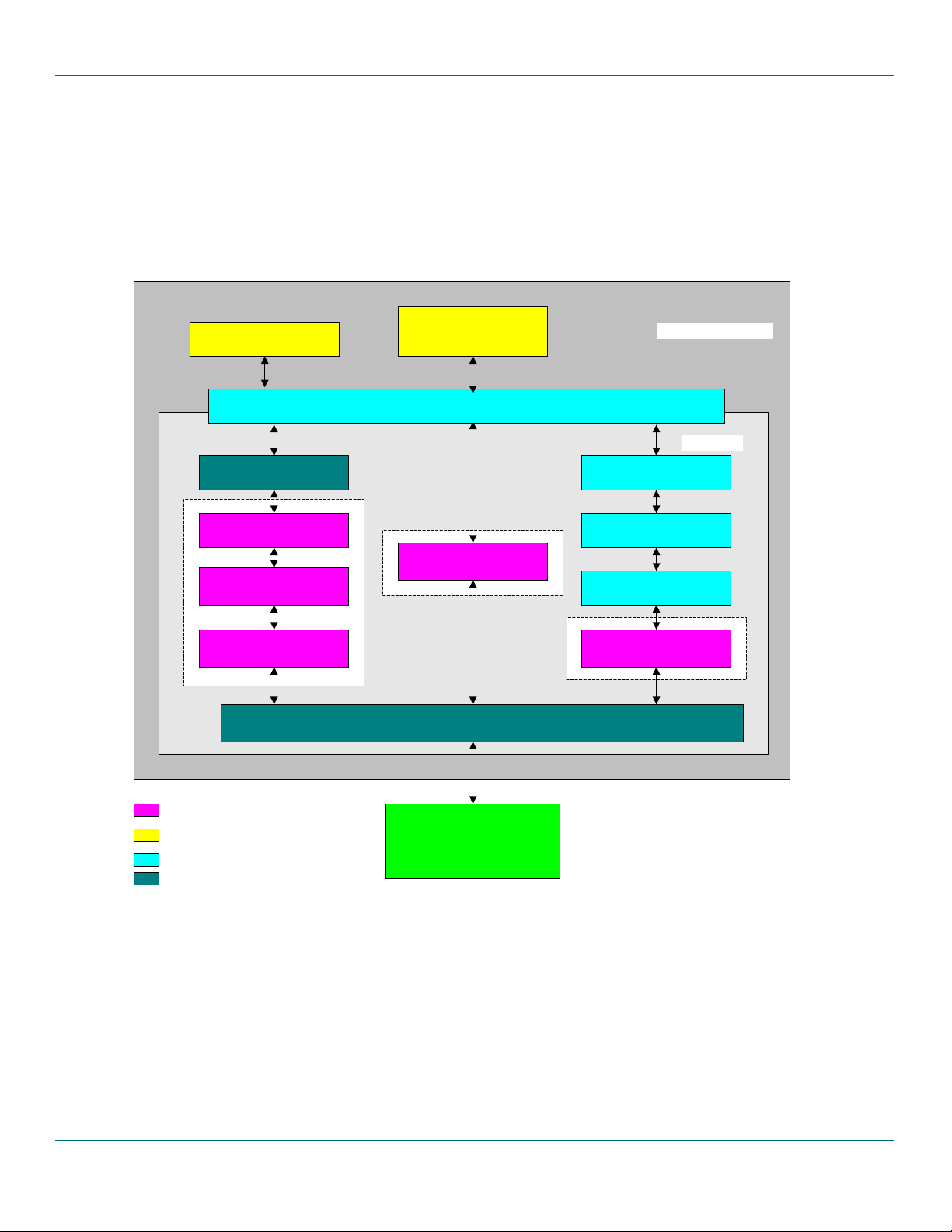
2.2. Stack Architecture
Figure 2-1 shows the software model of the ISP1362 Linux stack. The software stack consists of three modules,
shown in three colors:
• Core modules (these modules are platform-independent)
• Application demo modules
• Porting modules (these are platform-specific or product-specific modules that require porting).
The following subsections briefly explain each module.
UM10012-_2 © Koninklijke Philips Electronics N.V. 2003. All rights reserved.
User’s Guide Rev. 1.2—July 2003 6 of 34
Page 7
Philips Semiconductors ISP1362 Linux Stack User’s Guide
2.3. Core Modules
2.3.1. Host Stack
The host stack consists of the Host Controller Driver (HCD) module. The driver is used for data transfer on the
USB bus for the connected devices. This driver can work in parallel with other HCDs (OHCI HCD, UHCI HCD,
EHCI HCD) present in the kernel. This is a kernel module and the Linux OS has support for USB, connected USB
device class drivers and suitable applications.
Mass Storage disk
emulation
Mass Storage bridge
Mass Storage class driver
USB protocol driver
Device Controller Driver
OTG Mass storage demo/
OTG tools
Linux File System
OTG driver
ISP1362 Hardware Access Layer Driver
Linux operating system
Linux kernel
basic device drivers
USB class drivers
USB core
Host Controller Driver
ISP1362 stack core modules
ISP1362 application modules
Linux kernel drivers
ISP1362 porting modules
ISP1362 Hardware
Figure 2-1: ISP1362 Linux Stack Architecture
2.3.2. Device Stack
The device stack consists of the Device Controller Driver (DCD), the USB protocol driver, and the mass storage
class driver. The DCD is responsible for data transfer over the USB bus. The USB protocol driver responds to the
standard USB protocol requests. The mass storage class driver adds the mass storage functionality to the USB
device, and responds to the mass storage class commands and protocol. The mass storage needs to interface with
the physical mass storage device to perform its operations, and the physical disk is customer platform-specific and
UM10012-_2 © Koninklijke Philips Electronics N.V. 2003. All rights reserved.
User’s Guide Rev. 1.2—July 2003 7 of 34
Page 8

Philips Semiconductors ISP1362 Linux Stack User’s Guide
product-specific. Therefore, this driver communicates with a mass storage bridge (portable). For more information
on the device stack interface, refer to API ISP1362 Device Stack.
2.3.3. OTG Stack
The OTG stack consists of the OTG driver. This driver maintains the OTG software FSM, and coordinates the
host and device functionality switching. It interfaces with OTG applications through the Linux file system. For
more information on this interface, refer to API ISP1362 OTG Stack.
2.4. Application Modules
2.4.1. Mass Storage Disk Emulation
This module is an application module and emulates a physical disk. It responds to a minimal set of SCSI-II
commands, and uses a file system interface to store the physical disk data. This is developed for the OTG mass
storage demo purpose.
2.4.2. OTG Applications (OTG Mass Storage Demo/OTG Tools)
There are two OTG applications:
• A GUI-based application (for PC evaluation kits only)
• A command-line-based application
These applications are used to test the OTG mass storage functionality. These are written for the demo.
2.5. Porting Modules
2.5.1. Hardware Access Layer Driver
The core modules of the ISP1362 (Host Controller Driver, Device Controller Driver and OTG driver)
communicate with the ISP1362 hardware through this driver. Since hardware access is mostly platform-dependent,
this module must be ported to the target platform. This driver provides an interface to the ISP1362 registers and
buffers, to the ISP1362 I/O ports and interrupts, and configures the ISP1362 based on the platform.
2.5.2. Mass Storage Bridge
As physical storage disk is specific to the product, a mass storage bridge is needed. Also, as the mass storage disk
is an emulator in the application space, this layer provides an interface to the application module. You need to
port this layer to interface with the physical disk driver (kernel/application).
3. Installation
The ISP1362 evaluation boards are available in the following platforms:
• ISP1362 PCI evaluation kit
• ISP1362 ISA evaluation kit
TM
• ISP1362 add-on card for Intel PXA250-based Accelent® IDP
.
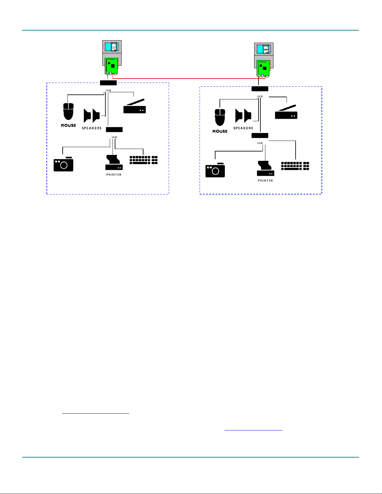
The ISP1362 Linux stack currently supports the ISP1362 PCI evaluation kit and ISP1362 add-on card for Accelent
IDP. Support for other platforms will soon be added to the stack. The same source code will work for all
platforms by changing the compile time options. The following diagram shows the evaluation kit setup example for
the ISP1362 Linux stack.
UM10012-_2 © Koninklijke Philips Electronics N.V. 2003. All rights reserved.
User’s Guide Rev. 1.2—July 2003 8 of 34
Page 9
Philips Semiconductors ISP1362 Linux Stack User’s Guide
ISP1362 Evaluation
Kit on Machine 1
OTG Cable
ISP1362 Evaluation
Kit on Machine 2
USB Peripherals on Machine 1
USB Peripherals on Machine 2
Figure 3-1: ISP1362 Linux Setup Example
3.1. ISP1362 PCI Evaluation Kit
3.1.1. Setting Up the PC and OS
For one evaluation kit, prepare one PC. The ISP1362 Linux stack does not support two or more boards on one
PC at the same time. Therefore, for the ISP1362 OTG evaluation, you must have two PCs.
The ISP1362 Linux stack can run on any X86 CPU (preferably, Intel
environment). The ISP1362 Linux stack on X86 PCI platform has been tested with Linux kernel version 2.4.20 on
Red Hat distribution. The stack should work with other distributions as well. Linux kernel versions 2.4.21 or
above need a different kernel patch for OTG. Therefore, it is preferable to have a PC running kernel version
2.4.20.
3.1.2. Setting Up the ISP1362 Evaluation Kit
The ISP1362 PCI evaluation kit can be configured in various modes of the ISP1362: the host-only mode, the
peripheral-only mode and the OTG mode. The OTG mode is the default mode for the evaluation kit as well as the
ISP1362 Linux stack. Make sure that the ISP1362 evaluation kit is configured in the OTG mode before using the
software. If you want to use any other mode of the ISP1362, refer to ISP1362 PCI Evaluation Board User’s Guide for
the hardware setup and Section
3.1.3. Setting Up the Software
5.1.1 for the software setup.
This section explains how to install the ISP1362 Linux stack. Explanation on the installation or setting up of USB
device-specific software is beyond the scope of this document.
®
Pentium® or above, for the desktop
3.1.3.1.Setting Up the Linux Kernel
1. Install the Linux kernel source code in a directory (This installation uses /usr/src/linux-otg/). If you do
not have the Linux kernel source code, you can download it from http://www.kernel.org/
UM10012-_2 © Koninklijke Philips Electronics N.V. 2003. All rights reserved.
.
User’s Guide Rev. 1.2—July 2003 9 of 34
Page 10

Philips Semiconductors ISP1362 Linux Stack User’s Guide
2. Copy the ISP1362 Linux stack (isp1362_linux_sw_stack.tar.gz) to a local directory (This installation
uses
/usr/src/linux-otg).
3. Apply the OTG patch to the kernel:
# cd /usr/src/linux-otg
# tar –zxvf /mnt/cdrom/isp1362_linux_sw_stack.tar.gz
# patch -p1 < 1362/misc/pci/otg_kernel_patch_pci
4. Configure, compile, install and run the new kernel. You can get information on how to configure, compile and
install the new kernel at http://www.tldp.org/HOWTO/kernel-HOWTO.html
. While configuring the kernel,
enable the following options for the ISP1362 Linux stack:
a. Code maturity level options
b. Loadable module support (enable all options)
c. Loop back device support (in block devices)
d. Any other USB options that need to be enabled
5. Reboot the PC, with the new kernel and the ISP1362 PCI evaluation kit.
3.1.3.2.Setting Up the ISP1362 Linux Stack
1. Go to the ISP1362 Linux software stack source top directory.
#cd /usr/src/linux-otg/1362/source
2. Edit the Rules.Make file for any changes in the compilation rules. The changes could be:
a. The kernel source directory is different from the one specified above.
b. Compile time flags, see Section 5.1. If you want any configuration changes. Make sure that PCI_KIT
hardware option is enabled.
3. Compile the ISP1362 Linux stack source code.
#make clean all install
Note: If the compilation fails due to non-existence of the glibconfig.h file, create a dummy file in the
/usr/include directory.
4. Make the setup for the OTG mass storage demo environment
# cd appl/tools
#make –f Makefile.setup
#./otgsetup.o
UM10012-_2 © Koninklijke Philips Electronics N.V. 2003. All rights reserved.
User’s Guide Rev. 1.2—July 2003 10 of 34
Page 11
Philips Semiconductors ISP1362 Linux Stack User’s Guide
g
3.2. ISP1362 Add-on Card for Intel PXA250 based Accelent IDP (Rev 04)
Accelent Systems developed the IDP - Integrated Development Platform to speed up the embedded device
development cycles. Accelent IDP provides a feature-rich, cost-effective development platform for embedded
device application and product development.
The ISP1362 Linux stack and the Accelent IDP do not support two or more boards at the same time. Therefore,
for the ISP1362 OTG evaluation, you must have two Accelent IDPs. The ISP1362 Linux stack on Intel PXA250based Accelent IDP platform has been tested with AccelLinux kernel version 2.4.18. Linux kernel versions 2.4.19
or above need a different kernel patch for OTG. Therefore, it is preferable to have Accelent IDP running on
kernel version 2.4.18.
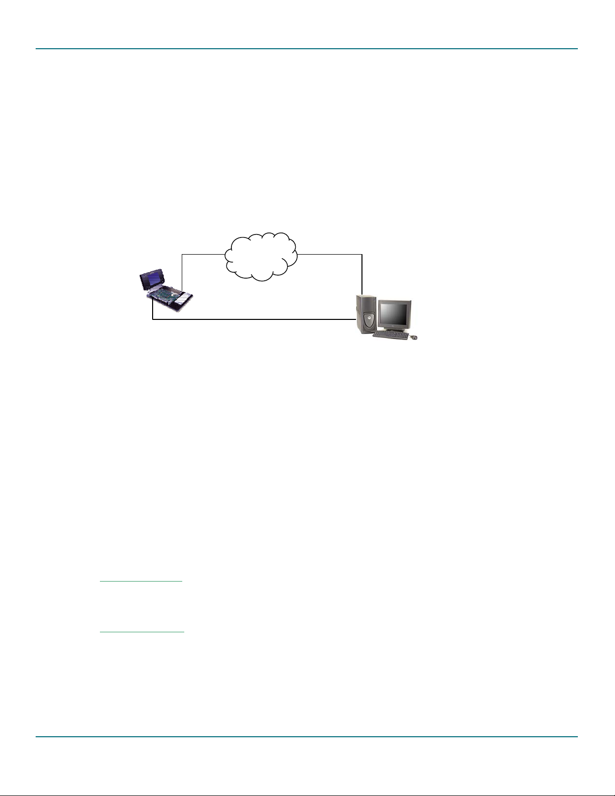
The following figure shows the development environment for Intel PXA250 based Accelent IDP with the ISP1362
evaluation kit.
LAN
Ethernet Cable
Accelent IDP
Runnin
Serial Port Cable
Linux
PC Host
Running Linux
Figure 3-2 Development setup for Intel PXA250 Based Accelent IDP
The following are the requirements for evaluating the ISP1362 stack on Accelent IDP:
• Two Intel PXA250-based Accelents IDPs
• PC host running the Linux operating system
• Installation CD for Accelent IDP
3.2.1. Setting Up the ISP1362 Add-On Card
The ISP1362 add-on card can be configured in various modes of the ISP1362: the host-only mode and the OTG
mode. The OTG mode is the default mode for the add-on card as well as the ISP1362 Linux stack. Make sure that
the ISP1362 add-on card is configured in the OTG mode before using the software. For more information on
hardware setup, refer to the ISP1362 OTG Add-On Evaluation Kit with Intel PXA250 IDP document.
3.2.2. Host PC Setup
Keep the Intel PXA250 based Accelent IDP installation CD on the CDROM drive.
3.2.2.3.Kernel Requirements
The Linux kernel on the Host PC should support ncurses library.
3.2.2.4.ARM Cross Compiler
The ARM toolchain can be copied from the CD provided by the Accelent (arm-linux-gcc2953.tar.bz2).
Don't bother trying to build the tool chain from scratch. The toolchain version 2.95.3 works very well. Don’t use
any of the gcc-3x compilers yet- they generate bad code for ARM in certain instances. Usually the ARM toolchain
should be unzipped in the root directory / of the host PC, using command:
UM10012-_2 © Koninklijke Philips Electronics N.V. 2003. All rights reserved.
User’s Guide Rev. 1.2—July 2003 11 of 34
Page 12

Philips Semiconductors ISP1362 Linux Stack User’s Guide
#cp /mnt/cdrom/Tools/tool_chain/arm-linux-gcc2953.tar.bz2 /
#cd /
#tar jxvf arm-linux-gcc2953.tar.bz2
(Older versions of tar might not accept this, then try using
#tar Ixvf arm-linux-gcc2953.tar.bz2)
Be careful about the root directory of the ARM cross compiler. arm-linux-gcc will invoke cpp0 and cc1 assuming
they reside in certain directories relative to the compiler’s root directory. To be on the safe side, unzip the ARM
tool chain in the root directory /.
Copy the utilities
bin2bin, foxfox, mkfs.jffs2, padkernel.py from Tools/utils directory of
Accelent CD to your execution path (like maybe /bin). These tools are needed to prepare Linux kernel and root
file system for loading into the target.
#cp /mnt/cdrom/Tools/utils/* /bin
#cd /bin
#chmod +x bin2bin foxfox mkfs.jffs2
padkernel.py
3.2.2.5.Linux Kernel source
The Linux kernel can be installed in to the PC host from the source code provided by the Accelent CD. Create a
directory for the source code (example /usr/src/AccelentIDPRev4) and go to the directory.
#cd /usr/src/AccelentIDPRev4
#bzip2 -cd /mnt/cdrom/Source/kernel/linux-2.4.18.tar.bz2 | tar xfv –
#bzip2 -cd /mnt/cdrom/Source/kernel/patch-2.4.18-rmk7.bz2 | patch -p0
#gzip -cd /mnt/cdrom/Source/kernel/patch-2.4.18-rmk7-pxa3.gz | patch -p0
#gzip -cd /mnt/cdrom/Source/kernel/releasepatch-2.4.18-rmk7-pxa3-asi2.gz | patch -p0
#cd linux
#make pxa_idp_config
#make oldconfig
ISP1362 stack release contains setup files related to Accelent IDP setup. First copy the ISP1362 release files
(isp1362_linux_sw_stack.tar.gz) to the current directory (
#tar –zxvf isp1362_linux_sw_stack.tar.gz
#patch -p1 <1362/misc/accelent_rev4/otg_kernel_patch_rev4
#cp /mnt/cdrom/Images/rootfs.tar.gz
/usr/src/AccelentIDPRev4/linux)
3.2.2.6.Linux Kernel Compliation
Makefile
Edit the Makefile of the kernel source (
/usr/src/AccelentIDPRev4/linux) CROSS_COMPILE path to the
path of the cross compiler
UM10012-_2 © Koninklijke Philips Electronics N.V. 2003. All rights reserved.
User’s Guide Rev. 1.2—July 2003 12 of 34
Page 13

Philips Semiconductors ISP1362 Linux Stack User’s Guide
CROSS_COMPILE = /pub/usr/ bin/arm-linux-
The cross compile path (/usr/include/arm/2.95.3) depends on where the tool chain is installed and the
version of the tool chain and from where the tool chain is downloaded.
Similarly edit the Rules.Make of ISP1362 source (
/usr/src/AccelentIDPRev4/linux/1362/source) for any
changes
• The kernel source directory is different from the one specified above.
• Compile time flags. Refer to section 5.1. If you want any configuration changes. Make sure that
PXA250_KIT hardware option is enabled with
•
CROSS_COMPILE path
MS_SIZE_FLAG is set to _8MB_SIZE_ (because of limitation of Accelent board for Mass storage
•
PXA250_REV4.
demo)
While configuring the kernel (use menuconfig), enable the following options:
USB core support
USB OTG support
USB Audio Support
USB mass storage support
USB pegasus
USB CATC
USB KAWTH
Save the configuration and exit
#make dep zImage modules modules_install jffs_rootfs jffs_image
As a result, a number of files starting with "nk_" will be created in the root Linux directory:
nk_jffs_flash.bin: This image includes the kernel and root filesystem
•
nk_kernel_flash.bin: This image is just the kernel image, useful if you already have a good root fs
•
image and just need to reflash the new kernel.
nk_kernel.bin : This is an image that will be loaded into RAM from the card without flashing
•
into ROM. It’s quite useful for debugging or preserving your flash image.
Whichever image you choose to use, copy it to the PCMCIA card and rename it "nk.bin". The card filename
must be nk.bin or the bootloader, which is WinCE bootloader, will ignore it.
3.2.2.7.Serial Communication for Debug Output
On the host PC running Linux, minicon can be used to receive debug output (generated by printk) from Accelent
IDP. A null-modem cable is required to connect FFUART(J5) port on Accelent IDP board and a COM port host
PC. Set Baud rate to 115200, data bits = 8, Parity = none, Stop bits = 1, Flow control = hardware.
3.2.3. Accelent IDP (Rev 04) Target Setup
Follow the instructions given in the Quick Start Guide IDP for Intel PXA250 Applications Processor Linux OS document
from the Accelent CD to set up the Accelent IDP.
UM10012-_2 © Koninklijke Philips Electronics N.V. 2003. All rights reserved.
User’s Guide Rev. 1.2—July 2003 13 of 34
Page 14

Philips Semiconductors ISP1362 Linux Stack User’s Guide
1. The boot loader boot.bin (from the accelent CD) does not support ISP1362 add-on card. Use the
boot loader from the ISP1362 stack release (/home/1362/AccelentIDP/boot.bin).
2. To load the new kernel and root file system from the development environment, copy the
nk_jffs_flash.bin from the earlier section as nk.bin to the CompactFlash card and boot up the
Accelent IDP. Follow the instructions on the Quick Start Guide IDP for Intel PXA250 Applications Processor
Linux O document for detailed loading/booting instructions.
3. Connect a CompactFlash card (size > 16MB) through the PCMCIA to a CompactFlash adapter. Log on to
the Accelent IDP as root and execute the following command (This is applicable for the demo
environment setup only)
#cd /home/1362/objs
#./imod
This will make the initial setup for the Accelent IDP for ISP1362 Linux stack. Note that you need to
execute this script for the first time only. Connect the Accelent IDP to the Linux host system as a mass
storage device, and perform the following steps on the host system.
4. Initialize and load the ISP1362 stack on to the target system as outlined in Section 4.2, and connect the
Accelent IDP to the host Linux PC as a mass storage device.
5. Write the following in a temporary file, say TempData, and give the file as an input to the fdisk
command
x
h
1
c
1024
2
16
r
n
p
1
p
w
The following values are made for an OTG mass storage disk of size 8 MB. Use the following
command on the host PC:
#fdisk /dev/sd[X] <TempData Where [X] could be (a/b/c/…z)
#mkdosfs –I /dev/sd[X]1
6. Unload and close the ISP1362 stack from the target system. Now the target system is ready for use.
3.3. ISP1362 Add-on Card for Intel PXA250 based Accelent IDP (Rev 02)
Accelent Systems developed the IDP - Integrated Development Platform to speed up the embedded device
development cycles. Accelent IDP provides a feature-rich, cost-effective development platform for embedded
device application and product development.
UM10012-_2 © Koninklijke Philips Electronics N.V. 2003. All rights reserved.
User’s Guide Rev. 1.2—July 2003 14 of 34
Page 15

Philips Semiconductors ISP1362 Linux Stack User’s Guide
g
The ISP1362 Linux stack and Accelent IDP does not support two or more boards at the same time. Therefore, for
the ISP1362 OTG evaluation, you must have two Accelent IDPs. The ISP1362 Linux stack on Intel PXA250 based
Accelent IDP platform has been tested with AccelLinux kernel version 2.4.18. Linux kernel versions 2.4.19 or
above need a different kernel patch for OTG. Therefore, it is preferable to have Accelent IDP running on kernel
version 2.4.18.
The following figure shows the development environment for Intel PXA250-based Accelent IDP with ISP1362
evaluation kit.
LAN
Ethernet Cable
Accelent IDP
Runnin
Serial Port Cable
Linux
PC Host
Running Linux
Figure 3-3 Development setup for Intel PXA250 Based Accelent IDP
The following are the requirements for evaluating the ISP1362 stack on Accelent IDP
• Two Intel PXA250 based Accelents IDPs
• PC host running the Linux operating system
• Installation CD for Accelent IDP
3.3.1. Setting Up the ISP1362 Add-On Card
The ISP1362 add-on card can be configured in various modes of the ISP1362: the host-only mode and the OTG
mode. The OTG mode is the default mode for the add-on card as well as the ISP1362 Linux stack. Make sure that
the ISP1362 add-on card is configured in the OTG mode before using the software. For more information on
hardware setup refer to the ISP1362 OTG Add-On Evaluation Kit with Intel PXA250 IDP document.
3.3.2. Host PC Setup
ISP1362 stack release contains setup files related to the Accelent IDP setup.
3.3.2.8.Kernel Requirements
The Linux kernel on the Host PC should support ncurses library.
3.3.2.9.ARM Cross Compiler
The ARM toolchain can be copied from the CD provided by the Accelent (arm_toolchain.tar.bz2). Do
not bother trying to build the tool chain from scratch. The tool chain version 2.95.3 works very well. Do not use
any of the gcc-3x compilers yet- they generate bad code for ARM in certain instances. Usually the ARM toolchain
should be unzipped in the root directory / of the host PC, using command:
UM10012-_2 © Koninklijke Philips Electronics N.V. 2003. All rights reserved.
User’s Guide Rev. 1.2—July 2003 15 of 34
Page 16

Philips Semiconductors ISP1362 Linux Stack User’s Guide
#cp /mnt/cdrom/tools/tool_chain/arm_toolchaintar.bz2 /
#cd /
#tar jxvf arm_toolchaintar.bz2 (Older versions of tar might not accept this, then try using #tar Ixvf
arm_toolchaintar.bz2)
Be careful about the root directory of the ARM cross compiler. arm-linux-gcc will invoke cpp0 and cc1 assuming
they reside in certain directories relative to the compiler’s root directory. To be on the safe side, unzip the ARM
tool chain in the root directory /.
Copy the utilities
bin2bin, foxfox, mkfs.jffs2, padkernel.py from tools\utils directory of
Accelent CD to your execution path (like maybe /bin). These tools are needed to prepare Linux kernel and root
file system for loading into the target.
#cp /mnt/cdrom/tools/utils/* /bin
#cd /bin
#chmod +x bin2bin foxfox mkfs.jffs2
3.3.2.10.Linux Kernel source
padkernel.py
The Linux kernel can be installed in to the PC host from the source code provided by the Accelent CD. Copy the
source code (linuxtar.bz2) from Accelent CD to known directory (example /usr/src).
#cd /usr/src
#bzip2 –cd /mnt/cdrom/source/linuxtar.bz2 |tar xfv –
#mv linux-2.4.18-rmk3-pxa2-asi1 /usr/src/linux-otg
Copy the ISP1362 stack related source to the kernel directory (
isp1362_linux_sw_stack.tar.gz). Apply
the ISP1362 specific kernel patch, otg_kernel_patch_rev2 from the ISP1362 Linux stack release to kernel
source.
#cd /usr/src/linux-otg
#tar –zxvf isp1362_linux_sw_stack.tar.gz
#patch -p1 <1362/misc/accelent_rev2/otg_kernel_patch_rev2
3.3.2.11.Root File System
Root file system for the IDP is provided in the Accelent CD. Copy the root file system rootfstar.bz2 to the
/usr/src/linux-otg directory.
#cp /mnt/cdrom/source/rootfstar.bz2 /usr/src/linux-otg
UM10012-_2 © Koninklijke Philips Electronics N.V. 2003. All rights reserved.
User’s Guide Rev. 1.2—July 2003 16 of 34
Page 17

Philips Semiconductors ISP1362 Linux Stack User’s Guide
3.3.2.12.Linux Kernel Configuration
Makefile
Edit the Makefile of the kernel source (
/usr/src/linux-otg) CROSS_COMPILE path to the path of the cross
compiler
CROSS_COMPILE = /pub/usr/ bin/arm-linux-
The cross compile path (/usr/include/arm/2.95.3) depends on where the tool chain is installed and the
version of the tool chain and from where the tool chain is downloaded.
Kernel Configuration
#cd /usr/src/linux-otg
#make pxa_idp_config
#make oldconfig
Note: For the make oldconfig step accept all the default options. You should use capital letters (N instead of n) to
disable an option, otherwise some weird compile errors will occur.
#make menuconfig
While configuring the kernel, enable the following options:
• Make the default RAM Disk size (from the options of block device/ Default Ram disk size) to 20480. We are
going to use the RAM disk as mass storage disk space.
• Enable loopback device support (from block device/loopback device support)
• Enable SCSI support and SCSI disk support
• Enable the USB (usb support), USB OTG support and the required USB Class drivers (USB audio, USB mass
storage etc,.) support.
3.3.2.13. ISP1362 Configuration
• Go to ISP1362 Linux Stack source directory
#cd /usr/src/linux-otg/1362/source
• Edit the Rules.Make file for any changes in compilation rules. The changes could be:
• The kernel source directory is different from the one specified earlier.
• Compile time flags. Refer to Section 5.1 if you want any configuration changes. Make sure that
PXA250_KIT hardware option is enabled with PXA250_REV2.
UM10012-_2 © Koninklijke Philips Electronics N.V. 2003. All rights reserved.
User’s Guide Rev. 1.2—July 2003 17 of 34
Page 18

Philips Semiconductors ISP1362 Linux Stack User’s Guide
• CROSS_COMPILE path
•
MS_SIZE_FLAG is set to _8MB_SIZE_ (because of limitation of Accelent board for Mass storage
demo)
3.3.2.14.OS Image Creation
To compile the kernel and create the final image to be downloaded into the IDP target, use the command:
#cd /usr/src/linux-otg/
#make dep zImage modules modules_install 1362_jffs_rootfs jffs_image
As a result, a number of files starting with "nk_" will be created in the root Linux directory:
nk_jffs_flash.bin: This image includes the kernel and root filesystem
•
nk_kernel_flash.bin: This image is just the kernel image, useful if you already have a good root fs
•
image and just need to reflash the new kernel.
•
nk_kernel.bin : This is an image that will be loaded into RAM from the card without flashing
into ROM. It’s quite useful for debugging or preserving your flash image.
Whichever image you choose to use, copy it to the PCMCIA card and rename it "nk.bin". The card filename
MUST be nk.bin or the bootloader, which is WinCE bootloader, will ignore it.
3.3.2.15.Serial Communication for Debug Output
On the host PC running Linux, minicon can be used to receive debug output (generated by printk) from Accelent
IDP. A null-modem cable is required to connect FFUART(J5) port on Accelent IDP board and a COM port host
PC. Set Baud rate to 115200, data bits = 8, Parity = none, Stop bits = 1, Flow control = hardware.
3.3.3. Accelent IDP Setup
Follow the instructions given in the Quick Start Guide IDP for Intel PXA250 Applications Processor Linux OS document
from the Accelent CD to set up the Accelent IDP.
1. The boot loader boot.bin (from the accelent CD) does not support ISP1362 add-on card. Use the
boot loader from the ISP1362 stack release (/home/1362/AccelentIDP/boot.bin).
2. To load the new kernel and root file system from the development environment, copy the
nk_jffs_flash.bin from the earlier section as nk.bin to the CompactFlash card, and boot up the
Accelent IDP. Follow the instructions on the Quick Start Guide IDP for Intel PXA250 Applications Processor
Linux OS document for detailed loading/booting instructions.
3. Log on to the Accelent IDP as root and execute the following command (This is applicable for the demo
environment setup only)
#cd /home/1362/objs
#./init_setup
This will make the initial setup for the Accelent IDP for ISP1362 Linux stack. Note that you need to
execute this script for the first time only. Connect the Accelent IDP to the Linux host system as a mass
storage device, and perform the following on the host system:
4. Initialize and load the ISP1362 stack on to the target system as mentioned in Section 4.2 and connect the
Accelent IDP to the host Linux PC as a mass storage device.
UM10012-_2 © Koninklijke Philips Electronics N.V. 2003. All rights reserved.
User’s Guide Rev. 1.2—July 2003 18 of 34
Page 19

Philips Semiconductors ISP1362 Linux Stack User’s Guide
5. Write the following in a temporary file, say TempData, and give the file as an input to the fdisk
command
x
h
1
c
1024
2
16
r
n
p
1
p
w
The following values are made for an OTG mass storage disk of size 8MB. Use the following
command on the host PC:
#fdisk /dev/sd[X] <TempData Where [X] could be (a/b/c/…z)
#mkdosfs –I /dev/sd[X]1
6. Unload and close the ISP1362 stack from the target system. Now the target system is ready for use.
4. Operating the ISP1362 Linux Stack
This chapter explains how to run the ISP1362 Linux stack after it has been successfully installed using the
procedures explained in the previous chapter.
In the OTG configuration, the ISP1362 Linux stack will act as a:
• USB host on the standard USB port.
• USB mass storage device on the OTG port when connected to a standard USB host via a Mini-B Standard-B
cable.
• USB OTG mass storage device on the OTG port when connected to other OTG devices.
For the limitations of the stack, refer to the Release Notes ISP1362 Linux Stack document.
4.1. ISP1362 PCI Evaluation Kit
4.1.1. Loading the Stack
The ISP1362 Linux stack modules (kernel as well as application) are dynamically loaded and unloaded to the
kernel.
1. Log on to the system as root, go to the ISP1362 Linux source directory and use the script to load modules.
#cd /usr/src/linux-otg/1362/source/objs
#./imod
2. If you execute the /sbin/lsmod command, you will notice that the following modules are loaded:
mscd, pdc, phci, otg, hal
UM10012-_2 © Koninklijke Philips Electronics N.V. 2003. All rights reserved.
User’s Guide Rev. 1.2—July 2003 19 of 34
Page 20

Philips Semiconductors ISP1362 Linux Stack User’s Guide
You should also see the msdisk application running as an application process when you list the current
running processes (
4.1.2. Unloading the Stack
ps).
1. As root of the system, go to the ISP1362 Linux source directory and use the script to unload module.
#cd /usr/src/linux-otg/1362/source/objs
#./rmod
2. If you execute the /sbin/lsmod command, you should not see any of the following modules as loaded:
mscd, pdc, phci, otg, hal
Also, you should not see the msdisk application as a running process when you list the current running
processes (
ps).
4.2. ISP1362 Add-on Card for Intel PXA250 based Accelent IDP (Rev 04)
4.2.1. Loading the Stack
The ISP1362 Linux stack modules (kernel as well as application) are dynamically loaded and unloaded to the
kernel.
1. Log on to the system as root, go to the ISP1362 object directory and use the script to load modules..
#cd /home/1362/objs
#./imod
2. If you execute the /sbin/lsmod command, you will notice that the following modules are loaded:
mscd, pdc, phci, otg, hal
You should also see the msdisk application running as an application process when you list the current
running processes (
4.2.2. Unloading the Stack
ps).
1. As root of the system, go to the ISP1362 Linux object directory and use the script to unload module.
#cd /home/1362/objs
#./rmod
2. If you execute the /sbin/lsmod command, you should not see any of the following modules as loaded:
mscd, pdc, phci, otg, hal
Also, you should not see the msdisk application as a running process when you list the current running
processes (
ps).
4.3. ISP1362 Add-on Card for Intel PXA250 based Accelent IDP (Rev 02)
4.3.1. Initializing the Stack
After booting the Accelent IDP needs some initial setup for the ISP1362 stack to run. The initialization is done by
executing the initialization script.
#cd /home/1362/objs
#./init_stack
UM10012-_2 © Koninklijke Philips Electronics N.V. 2003. All rights reserved.
User’s Guide Rev. 1.2—July 2003 20 of 34
Page 21

Philips Semiconductors ISP1362 Linux Stack User’s Guide
This script mounts the OTG mass storage disk data from Accelent IDP ROM to RAM.
4.3.2. Loading the Stack
The ISP1362 Linux stack modules (kernel as well as application) are dynamically loaded and unloaded to the
kernel.
• Log on to the system as root, go to the ISP1362 object directory and use the script to load modules.
#cd /home/1362/objs
#./imod
• If you execute the /sbin/lsmod command, you will notice that the following modules are loaded:
mscd, pdc, phci, otg, hal
You should also see the msdisk application running as an application process when you list the current
running processes (
4.3.3. Unloading the Stack
ps).
• As root of the system, go to the ISP1362 Linux source directory and use the script to unload module.
#cd /home/1362/objs
#./rmod
• If you execute the /sbin/lsmod command, you should not see any of the following modules as loaded:
mscd, pdc, phci, otg, hal
Also, you should not see the msdisk application as a running process when you list the current running processes
(
ps).
4.3.4. Closing the ISP1362 Stack
Before the Accelent IDP is shutdown, you need to close the ISP1362 stack to copy the OTG mass storage data
changes in the RAM to the ROM. To do so, execute:
#cd /home/1362/objs
#./close_stack
4.4. ISP1362 Host Stack
Working with the ISP1362 host stack is similar to working with any other Host Controller on Linux. Once the
ISP1362 stack modules are loaded, you can work with any devices connected to the standard USB port of the
ISP1362 evaluation kit—assuming the kernel has drivers, root file system has application and proper environment
is set for the corresponding connected device. A generic example on setting up the host stack evaluation is given
in the following diagram.
UM10012-_2 © Koninklijke Philips Electronics N.V. 2003. All rights reserved.
User’s Guide Rev. 1.2—July 2003 21 of 34
Page 22

Philips Semiconductors ISP1362 Linux Stack User’s Guide
ISP1362 Evaluation
Kit on Machine 1
USB Peripherals on Machine 1
Figure 4-1: Host Stack Evaluation Example Setup
In Figure 4-1, the requirements for the connected devices to work are:
• The Linux kernel has class drivers or drivers corresponding to the connected USB device enabled and loaded.
• The Linux OS has the appropriate application to work with the connected device.
Explanation on setting of environment for various USB devices is beyond the scope of this document.
4.5. ISP1362 Device Stack
Once the ISP1362 modules are loaded, you can connect the ISP1362 to any other PC USB host through the Mini-B
to Standard-B cable. The ISP1362 device will appear as a mass storage device (removable disk). The following
figure shows the device stack evaluation setup:
ISP1362 Evaluation
Kit on Machine 1
OTG Mini-B to
Standard-B Cable
Figure 4-2: Device Stack Evaluation Setup
PC as Standard USB
Host
UM10012-_2 © Koninklijke Philips Electronics N.V. 2003. All rights reserved.
User’s Guide Rev. 1.2—July 2003 22 of 34
Page 23

Philips Semiconductors ISP1362 Linux Stack User’s Guide
When connected to another USB host, with the ISP1362 as a device, you can:
• See the mass storage as a removable disk (capacity of 16 MB including the file system)
• See the contents of the disk
• Read/write the contents of the disk
• Format the disk (FAT16, EXT2 file systems)
• Partition the disk into smaller disks.
4.6. ISP1362 OTG Stack
To work with the OTG stack, you need to run either the otg commands from the tools directory or OTG demo
from the
otgmsdemo directory. Figure 4-3 shows the OTG stack evaluation setup.
ISP1362 Evaluation
Kit on Machine 1
OTG cable
ISP1362 Evaluation
Kit on Machine 2
Standard USB devices
Standard USB devices
Figure 4-3: OTG Stack Evaluation Setup
The
otgmsapp application is the OTG mass storage demo application using GTK. Go to the otgmsdemo
directory, and launch the application:
#cd /home/1362/objs
#./otgmsapp
This program will launch a new window. Note: this program will work only on machines that support GTK and
Windows. The Accelent IDP does not support this application.
The following is a snapshot of the application when a Mini-A cable is connected to the OTG port after the
application is launched. The application shows the status of the OTG port activity (HOST, IDLE and DEVICE).
In the IDLE state, the OTG disks of the local OTG device disk (on which the application is running) and the
remote OTG device disk (the connected OTG device) are not visible.
UM10012-_2 © Koninklijke Philips Electronics N.V. 2003. All rights reserved.
User’s Guide Rev. 1.2—July 2003 23 of 34
Page 24

Philips Semiconductors ISP1362 Linux Stack User’s Guide
Figure 4-4: OTG Mass Storage Application in the IDLE State Snapshot
Figure 4-5: OTG Mass Storage Application in the HOST State Snapshot
The application has a provision to change the state from IDLE to HOST and HOST to IDLE. In the HOST state,
both the local OTG device disk and the remote OTG device disk (connected) will be mounted and available for
use.
UM10012-_2 © Koninklijke Philips Electronics N.V. 2003. All rights reserved.
User’s Guide Rev. 1.2—July 2003 24 of 34
Page 25

Philips Semiconductors ISP1362 Linux Stack User’s Guide
Figure 4-5 shows a snapshot of the application in the HOST state when a Mini-B plug is connected to the OTG
port. In the HOST state, both the local and remote OTG device disks are mounted and are available for
operation. You can select files from the source disk and transfer (copy or move) the files to the destination disk.
You can also select the source and destination disks to be local or remote.
Figure 4-6 shows the file selection menu for the source/destination disks. You can delete the files from the disk by
selecting the file and pressing the Delete button on the keyboard. The Status Pad window shows the status of the
operation with appropriate messages.
The application transfers files from the source disk to the destination disk only. If you want to transfer files the
other way, change the source disk from local to remote and the destination disk from remote to local.
Figure 4-7 shows a snapshot of the OTG application when a Mini-A plug is inserted and the remote OTG device is
the host.
Figure 4-6: OTG Application File Selection Snapshot
UM10012-_2 © Koninklijke Philips Electronics N.V. 2003. All rights reserved.
User’s Guide Rev. 1.2—July 2003 25 of 34
Page 26

Philips Semiconductors ISP1362 Linux Stack User’s Guide
Figure 4-7: OTG Application as a Device Snapshot
Another way to use the OTG mass storage is by using the command-line application in the tools directory. To see
the list of options supported by this command, use the help option.
#cd /home/1362/objs
#./otgcmd.o help
The following table provides a list of
Table 4-1: OTG Command Line tool Options
otgcmd.o options and their description:
Option Description
host
Becomes the USB bus host on the OTG port. Once it becomes the host, it enumerates any device
connected to the host on the OTG port
idle
If the OTG device is the bus host on the OTG port, de-enumerates the connected USB device and
comes out of the bus host.
load
unload
mount
Loads OTG modules
Unloads OTG modules
If the OTG device is the USB bus host on the OTG port and the connected device is a mass storage
device, mounts both the local OTG device disk and the remote OTG device disk to the mount points.
umount
If the local OTG device disk and the remote OTG device disk are mounted to the mount points,
unmounts both these devices.
status
help
Current state of the OTG port and the OTG device disks mount status.
Prints help menu.
To operate the OTG mass storage device as a host, connect the other OTG mass storage device through the
OTG cable and execute the following on one of the targets:
1. #./otgcmd host
This command will make the OTG mass storage device as a USB host on the executed target.
UM10012-_2 © Koninklijke Philips Electronics N.V. 2003. All rights reserved.
User’s Guide Rev. 1.2—July 2003 26 of 34
Page 27

Philips Semiconductors ISP1362 Linux Stack User’s Guide
2. #./otgcmd mount
This command will mount the local and connected OTG mass storage disks to the specified mount points
and the disks are ready for use.
To disconnect the OTG mass storage device, follow these steps:
1. #./otgcmd umount
This command will unmount the already mounted local and connected OTG mass storage disks.
2. #./otgcmd idle
This command will bring the OTG mass storage device to idle state.
To get the status of the OTG mass storage device at any time, use the following command:
• #./otgcmd status
This command will print the current state of the OTG device, the mount status of the local and remote
connected OTG device.
In case of VBUS error, you can clear the status using:
• #./otgcmd error
This will clear the error condition on the USB bus
The following pictures shows snapshots of Accelent target screen during operation.
Figure 4-8 OTG B device accessing remote OTG mass storage device files
UM10012-_2 © Koninklijke Philips Electronics N.V. 2003. All rights reserved.
User’s Guide Rev. 1.2—July 2003 27 of 34
Page 28

Philips Semiconductors ISP1362 Linux Stack User’s Guide
Figure 4-9 OTG B closing the session after connected device data access
Figure 4-8 shows the screen capture of otgcmd.o utility when running on the Accelent IDP platform. It shows
the execution of otgcmd.o for current status, becoming usb host, mounting the connected device disks and
accessing the connected OTG mass storage device (A device) files.
Figure 4-9 shows the screen captures of otgcmd.o while copying files from connected OTG mass storage disk to
the local disk, playing an MP3 file from the connected OTG mass storage device, and going back to IDLE state. It
also shows the screen capture of help option with otgcmd.o
Figure 4-10 shows screen captures of OTG B device status as peripheral when connected to OTG A host,
accessing the local disk files when in IDLE state and OTG status as OTG A device.
UM10012-_2 © Koninklijke Philips Electronics N.V. 2003. All rights reserved.
User’s Guide Rev. 1.2—July 2003 28 of 34
Page 29

Philips Semiconductors ISP1362 Linux Stack User’s Guide
Figure 4-10 Operations with OTG A and B devices
UM10012-_2 © Koninklijke Philips Electronics N.V. 2003. All rights reserved.
User’s Guide Rev. 1.2—July 2003 29 of 34
Page 30

Philips Semiconductors ISP1362 Linux Stack User’s Guide
5. Configuration
The ISP1362 Linux stack can be configured to work in different ways by using the static compilation time flags. The
Rules.Make file in the root directory of the source code selects the global compilation flags. The local
compilation flags for the modules are selected in the
5.1. Compilation Flags
5.1.1. Global
Table 5-1 shows the compilation flags that are selected in the Rules.Make file and their description:
Table 5-1: Global Compilation Flags
Compilation Flag Description
DCONFIG_USB_HCDC_OTG
DCONFIG_1362_PCI
DCONFIG_1362_ISA
DCONFIG_1362_SA
_16MB_SIZE_
DCONFIG_FUNC_DEBUG
DCONFIG_DETAIL_DEBUG
PHCI_DEBUG
PDC_DEBUG
OTG_DEBUG
HAL_DEBUG
MSCD_DEBUG
Configures the OTG mode.
• In the non-OTG mode, only the host stack is enabled without OTG functionality.
• In the OTG mode, all the modules are enabled.
This compilation flag is for the ISP1362 PCI evaluation kit hardware.
This compilation flag is for the ISP1362 ISA evaluation kit hardware.
This compilation flag is for the ISP1362 PXA250 kit hardware.
Mass Storage disk size of 16 MB.
Configures function level debugging. When this flag is enabled, the stack prints all
function entry traces.
Configures detail level debugging. When this flag is enabled, the stack prints function
entry traces as well as any important detail level traces.
Enables debugging for the Host Controller Driver. The trace level depends on the
global compilation flags:
Enables debugging for the Device Controller Driver. The trace level depends on the
global compilation flags:
Enables debugging for the OTG Controller Driver. The trace level depends on the
global compilation flags:
Enables debugging for the HAL driver. The trace level depends on the global
compilation flags:
Enables debugging for the mass storage class driver. The trace level depends on the
global compilation flags:
Makefile of the corresponding module directory.
CONFIG_FUNC_DEBUG and CONFIG_DETAIL_DEBUG.
CONFIG_FUNC_DEBUG and CONFIG_DETAIL_DEBUG.
CONFIG_FUNC_DEBUG and CONFIG_DETAIL_DEBUG.
CONFIG_FUNC_DEBUG and CONFIG_DETAIL_DEBUG.
CONFIG_FUNC_DEBUG and CONFIG_DETAIL_DEBUG.
5.1.2. Host Controller Driver
Table 5-2 shows the Host Controller Driver compilation flags that are selected in Makefile and their description.
Table 5-2: Host Controller Driver Compilation Flags
Compilation Flag Description
CONFIG_USB_PHCD_EVEN_SCH
Configures the ISP1362 interrupt transfer event scheduling. By enabling this flag,
the interrupt transfers are evenly scheduled over a period of 32 ms.
CONFIG_USB_PHCD_PING_PONG
Configures the ISP1362 ping pong mechanism. Use the ISP1362 ping pong
mechanism for the bulk transfers to achieve maximum transfer per millisecond on
the USB bus.
CONFIG_PHCI_MEM_SLAB
Use memory pool for the HCD endpoint descriptor and Transfer descriptor data
structures.
UM10012-_2 © Koninklijke Philips Electronics N.V. 2003. All rights reserved.
User’s Guide Rev. 1.2—July 2003 30 of 34
Page 31

Philips Semiconductors ISP1362 Linux Stack User’s Guide
6. Inside the ISP1362 Linux Stack
The ISP1362 Linux stack release consists of two parts: a Linux kernel OTG patch for kernel version 2.4.18 and the
ISP1362 Linux stack source code.
The code is written in C. This chapter explains the ISP1362 Linux stack source code organization.
6.1. Top-Level Directory
The root directory consists of all the substack directories and the make files. Table 6-1 shows the contents of this
directory and their description.
Table 6-1: Top-Level Directory Contents
File Name Description
release/Makefile
release/Rules.Make
release/host
release/device
release/otg
release/hal
Release/appl
release/objs
Top-level Makefile that compiles all the subdirectories
Top-level make file rules
ISP1362 host stack directory
ISP1362 device stack directory
ISP1362 OTG stack directory
ISP1362 hardware access layer directory
ISP1362 OTG mass storage application modules directory
ISP1362 Linux stack object files directory
6.2. host
The host directory consists of files and directories related to the ISP1362 host stack. The contents of this
directory and their description are given in Table 6-2.
Table 6-2: Contents of the host Directory
File Name Description
release/host/Makefile
release/host/phci/
6.2.1. phci
Makefile for the host stack
ISP1362 Host Controller Driver directory
The phci directory consists of files related to the ISP1362 Host Controller Driver. The following table shows the
contents of this directory and their description.
Table 6-3: Contents of the phci Directory
File Name Description
release/host/phci/Makefile
release/host/phci/usb_phci.c
release/host/phci/usb_phci.h
Makefile for the Host Controller Driver
ISP1362 Host Controller Driver C source file
ISP1362 Host Controller Driver C header file
6.3. device
The device directory consists of files related to the ISP1362 device stack. Table 6-4 shows the contents of the
device directory and their description.
UM10012-_2 © Koninklijke Philips Electronics N.V. 2003. All rights reserved.
User’s Guide Rev. 1.2—July 2003 31 of 34
Page 32

Philips Semiconductors ISP1362 Linux Stack User’s Guide
Table 6-4: Contents of the device Directory
File Name Description
release/device/Makefile
release/device/pdc
release/device/devmscd
release/device/diskemu
6.3.1. pdc
Makefile for the device stack subdirectories
ISP1362 Device Controller Driver C source file
ISP1362 Device Controller Driver C header file
ISP1362 USB protocol driver C source file
The pdc directory consists of files related to the ISP1362 Device Controller Driver and USB protocol driver. The
following table shows the contents of the
Table 6-5: Contents of the pdc Directory
pdc directory and their description:
File Name Description
release/device/pdc/Makefile
release/device/pdc/usb_pdc.c
release/device/pdc/usb_pdc.h
release/device/pdc/pdc_bus.c
release/device/pdc/pdc_bus.h
release/device/pdc/pdc_protocol.h
release/device/pdc/pdc_intf.h
Makefile for the Device Controller Driver
ISP1362 Device Controller Driver C source file
ISP1362 Device Controller Driver C header file
ISP1362 USB protocol driver C source file
ISP1362 USB protocol driver C header file
ISP1362 USB protocol definitions C header file
ISP1362 Device Controller Driver, USB protocol driver
interface C header file
6.3.2. devmscd
The devmscd directory consists of files related to the mass storage class driver (the device side) and the mass
storage bridge. Table 6-6 shows the contents of the
Table 6-6: Contents of the devmscd Directory
devmscd directory and their description:
File Name Description
release/device/devmscd/Makefile
release/device/devmscd/devmscd.c
release/device/devmscd/devmscd.h
release/device/devmscd/msbridge.c
release/device/devmscd/msbridge.h
Makefile for the device side mass storage class driver
USB mass storage BOT class driver C source file
USB mass storage BOT class driver C header file
USB mass storage bridge C source file
USB mass storage bridge to mass storage disk emulation
interface C header file
release/device/devmscd/mscdbridge.h
USB mass storage class driver to mass storage bridge C header
file
6.3.3. diskemu
The diskemu directory consists of files related to the mass storage disk emulation. Table 6-7 shows the contents
of this directory and their description:
Table 6-7: Contents of the diskemu Directory
File Name Description
release/device/diskemu/Makefile
release/device/diskemu/disk_emu.c
release/device/diskemu/disk_emu.h
Makefile for the disk emulator module
SCSI-II mass storage disk emulation C source file
SCSI-II mass storage disk emulation C header file
6.4. otg
The otg directory consists of files related to the ISP1362 OTG Controller Driver. The contents of the otg
directory and their description are given in Table 6-8.
UM10012-_2 © Koninklijke Philips Electronics N.V. 2003. All rights reserved.
User’s Guide Rev. 1.2—July 2003 32 of 34
Page 33

Philips Semiconductors ISP1362 Linux Stack User’s Guide
Table 6-8: Contents of the otg Directory
File Name Description
release/otg/Makefile
release/otg/usb_otg.c
release/otg/usb_otg.h
release/otg/otg_fsm.c
release/otg/otg_fsm.h
Makefile for the OTG Controller Driver
ISP1362 OTG Controller Driver C source file
ISP1362 OTG Controller Driver interface C header file
ISP1362 USB OTG software FSM C source file
ISP1362 USB OTG software FSM C header file
6.5. hal
The hal directory consists of files related to the ISP1362 platform porting, hardware access directories and the
interface header files. The following table shows the contents of the
Table 6-9: Contents of the hal Directory
File Name Description
release/hal/Makefile
release/hal/hal_intf.h
release/hal/x86pci
6.5.1. x86pci
Makefile for the ISP1362 hardware access layer driver
ISP1362 hardware access layer interface C header file
ISP1362 HAL PC X86 PCI directory
The x86pci directory consists of files related to the ISP1362 X86 PCI platform HAL porting files. The following
table shows the contents of this directory and their description:
hal directory and their description:
Table 6-10: Contents of the x86pci Directory
File Name Description
release/hal/x86pci/Makefile
release/hal/x86pci/hal_pci.c
release/hal/x86pci/hal_pci.h
Makefile for the ISP1362 X86 PCI HAL
ISP1362 hardware access layer PCI X86 platform C source file
ISP1362 hardware access layer PCI X86 platform C header file
6.6. appl
The appl directory consists of files and directories related to the ISP1362 mass storage demo applications. The
following table shows the contents of this directory and their description:
Table 6-11: Contents of the appl Directory
File Name Description
release/appl/Makefile
release/appl/otgmsdemo/
release/appl/tools
6.6.1. otgmsdemo
The otgmsdemo directory consists of files related to the OTG mass storage GUI demo application. Table 6-12
shows the contents of this directory and their description:
Table 6-12: Contents of the otgmsdemo Directory
File Name Description
release/appl/otgmsdemo/Makefile
release/appl/otgmsdemo/otgmsapp.c
release/appl/otgmsdemo/otgmsapp.h
Makefile for the OTG mass storage demo application directories
ISP1362 OTG mass storage demo application directory
ISP1362 OTG mass storage demo tools directory
Makefile for the OTG mass storage demo application
ISP1362 OTG mass storage demo application C source file
ISP1362 OTG mass storage demo application C header file
UM10012-_2 © Koninklijke Philips Electronics N.V. 2003. All rights reserved.
User’s Guide Rev. 1.2—July 2003 33 of 34
Page 34

Philips Semiconductors ISP1362 Linux Stack User’s Guide
6.6.2. tools
The tools directory consists of files related to the mass storage disk emulation. The contents of this directory
and their description are given in Table 6-13.
Table 6-13: Contents of the tools Directory
File Name Description
release/appl/tools/Makefile
release/appl/tools/otgcmd.c
release/appl/tools/otgtool.h
release/appl/tools/Makefile.setup
release/appl/tools/otgsetup.c
Makefile for the OTG command-line tools application
ISP1362 OTG mass storage command application C source file
ISP1362 OTG mass storage applications C header file
Makefile for the OTG environment setup application
ISP1362 OTG mass storage demo/evaluation environment setup
application C source file
6.7. objs
The objs directory consists of files related to the compiled objects and scripts to load and unload the modules.
This directory initially consists of script files, and once the compiled objects are installed the object files will also
occupy this directory.
Table 6-14: Contents of the objs Directory
File Name Description
release/objs/imod
release/objs/rmod
Script file to load OTG mass storage modules
Script file to unload OTG mass storage modules
7. References
• Universal Serial Bus Specification Rev. 2.0
• On-The-Go Supplement to the USB 2.0 Specification Rev. 1.0
• ISP1362 Single-chip Universal Serial Bus On-The-Go controller datasheet
• ISP1362 PCI Evaluation Board User’s Guide
• API ISP1362 Host Stack
• API ISP1362 Device Stack
• API ISP1362 OTG Stack
• Release Notes ISP1362 Linux Stack
• Quick Start Guide IDP for Intel PXA250 Applications Processor Linux OS
• Software User Guide IDP for Intel PXA250 Applications Processor Linux OS
• ISP1362 OTG Add On Evaluation Kit with Intel PXA250 IDP
UM10012-_2 © Koninklijke Philips Electronics N.V. 2003. All rights reserved.
User’s Guide Rev. 1.2—July 2003 34 of 34
Page 35

Philips Semiconductors
Philips Semiconductors is a worldwide company with over 100 sales
offices in more than 50 countries. For a complete up-to-date list of our
sales offices please e-mail
sales.addresses@www.semiconductors.philips.com.
A complete list will be sent to you automatically.
You can also visit our website
http://www.semiconductors.philips.com/sales/
www.semiconductors.philips.com
© Koninklijke Philips Electronics N.V. 2003
All rights reserved. Reproduction in whole or in part is prohibited
without the prior written consent of the copyright owner. The information presented in this document does not form part of any quotation or contract, is believed to be accurate and reliable and may be
changed without notice. No liability will be accepted by the publisher
for any consequence of its use. Publication thereof does not convey
or imply any license under patent – or other industrial or intellectual
property rights.
 Loading...