


ISP1130
Universal Serial Bus compound hub with integrated keyboard
controller
Rev. 01 — 23 March 2000 Objective specification
1. General description
The ISP1130 integrates a Universal Serial Bus (USB) hub with a keyboard controller
into a single chip,whichcomplieswith
the USB
1 to 2 downstream ports and 1 to 3 non-removable embedded functions, one of
which is dedicated to the keyboard operation. The hub controller is fully implemented
in hardware, ensuring a fast response to host requests.
The integrated 5 V to 3.3 V regulator allows direct connection to the USB power
supply V
can interface low-power USB devices such as a joystick or a mouse. ISP1130 uses
SoftConnect™ technology to connect to the USB host upon detection of V
low power consumption in ‘suspend’ mode allows easy design of equipment that is
compliant with the ACPI™, OnNow™ and USB power management requirements.
UniversalSerial Bus Specification Rev. 1.1
Device Class Definition for Human Interface Devices (HID)
. The downstream ports are either bus-powered or hybrid-powered and
BUS
. The hub has
BUS
and
. The
2. Features
The integrated keyboard controller is based on the 80C51 family and has 8 kbytes of
mask ROM and 256 bytes of data RAM. The code memory is protected against
reading by an external device. A built-in watchdog timer resets the device in case of a
microcontroller hang-up. To reduce power consumption, the microcontroller can be
c
c
put in sleep mode or power-down mode.
A serial I2C-bus interface is provided for optional access to an external EEPROM.
This allows the user to program the vendor ID, product ID or activate the built-in
keyboard matrix.
The ISP1130 has built-in overcurrent sense inputs, supporting individual and global
overcurrent protection for downstream ports. All ports (including the hub) have
GoodLink™ indicator outputs for easy visual monitoring of USB traffic. The ISP1130
has a reduced frequency (6 MHz) crystal oscillator to minimize Electro Magnetic
Interference (EMI). These features allow significant cost savings in system design
and easy implementation of advanced USB functionality into PC peripherals.
■ Compound USB hub device with integrated hub repeater, hub controller, Serial
Interface Engine (SIE), data transceivers and 5 V to 3.3 V voltage regulator
■ Complies with
Universal Serial Bus Specification Rev. 1.1
and
Device Class
Definition for Human Interface Devices (HID)
■ Complies with ACPI, OnNow and USB power management requirements

Philips Semiconductors
■ Supports bus-powered and hybrid-powered application
■ 1 to 2 downstream ports with automatic speed detection
■ 1 to 3 non-removable embedded functions, 1 dedicated for keyboard operation
■ 8 × 18 scan line matrix for HID compliant keyboard applications
■ Integrated 80C51 microcontroller core with 8 kbytes mask ROM and 256 bytes
■ On-chip watchdog timer for automatic fault recovery
■ Internal power-on reset and low-voltage reset circuit
■ Individual power switching for downstream ports
■ Individual port overcurrent protection with built-in sense circuits
■ 6 MHz crystal oscillator with on-chip PLL for low EMI
■ Reduced power consumption by putting microcontroller in sleep mode or
■ Visual USB traffic monitoring (GoodLink) for hub and downstream ports
■ I2C-bus interface to read vendor ID, product ID and configuration bits from
■ Operation over the extended USB bus voltage range (4.0 to 5.5 V)
■ Operating temperature range −40 to +85 °C
■ Available in 56-pin SDIP and SSOP packages.
ISP1130
USB compound hub with keyboard controller
data RAM
power-down mode
external EEPROM
3. Ordering information
Table 1: Ordering information
Type number Package
Name Description Version
ISP1130DL SSOP56 plastic shrink small outline package; 56 leads; body width 7.5 mm SOT371-1
ISP1130N SDIP56 plastic shrink dual in-line package; 56 leads (600 mil) SOT400-1
9397 750 06895
Objective specification Rev. 01 — 23 March 2000 2 of 68
© Philips Electronics N.V. 2000. All rights reserved.
Philips Semiconductors
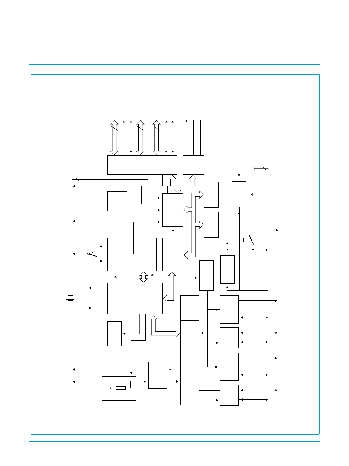
4. Block diagram
to/from
keyboard
MX0
to MX2
3
18 to 20
MX5
MX3/SCL22MX4/SDA
3
21
23 to 25
to MX7
26 to 28,
MY0
to MY15
MY16/RD45MY17/WR55CAPSLOCK
16
44
31 to 43
SCRLOCK
53
ISP1130
USB compound hub with keyboard controller
NUMLOCK
54
MGS811
andbook, full pagewidth
6 MHz
2
EA, INT
2
ALE, PSEN
4847 49, 5250, 51
SYNCLK
MEMSEL/UPGL
XTAL2
XTAL1
12
WATCH
PROGRAM
to LED to EEPROM
48
MHz
PLL
HUB
MX
KEY
DOG
TIMER
MCU_CLOCK
DIVIDER
BIT CLOCK
RECOVERY
OSCILLATOR
GoodLink
PORTS
MATRIX
INT0
HUB
CONTROLLER
SIE
PHILIPS
MY
INT1
MICRO-
DEVICE
LED
80C51
CONTROLLER
HANDLER
16 BYTES RAM
FRAME
END OF
PORTS
PORT
TIMERS
ISP1130
RAM
256 BYTES
8 kBYTE
MASK ROM
internal
supply
3.3 V
VOLTAGE
REGULATOR
CONTROLLER
5 V
GoodLink
OC DETECT
ANALOG
internal
reset
RESET
POWER-ON
Connect
POWER SW
Tx/Rx
4
GND
36 5, 17, 29, 46, 56
RESET
pu(3.3)
V
30
reg(3.3)
V
CC
V
14 416
PSW2
OC2/DPGL2DN2_DP
1112
DN2_DM
13
PSW1
OC1/DPGL1
downstream port 1 downstream port 2
DN1_DM
DN1_DP
9397 750 06895
UP_DMUP_DP
upstream port
1.5
kΩ
SoftConnect
Tx/Rx
ANALOG
78
3.3 V
HUB
REPEATER
GoodLink
POWER SW
OC DETECT
Tx/Rx
ANALOG
15
9
10
© Philips Electronics N.V. 2000. All rights reserved.
Objective specification Rev. 01 — 23 March 2000 3 of 68
Fig 1. Block diagram of ISP1130.
Philips Semiconductors
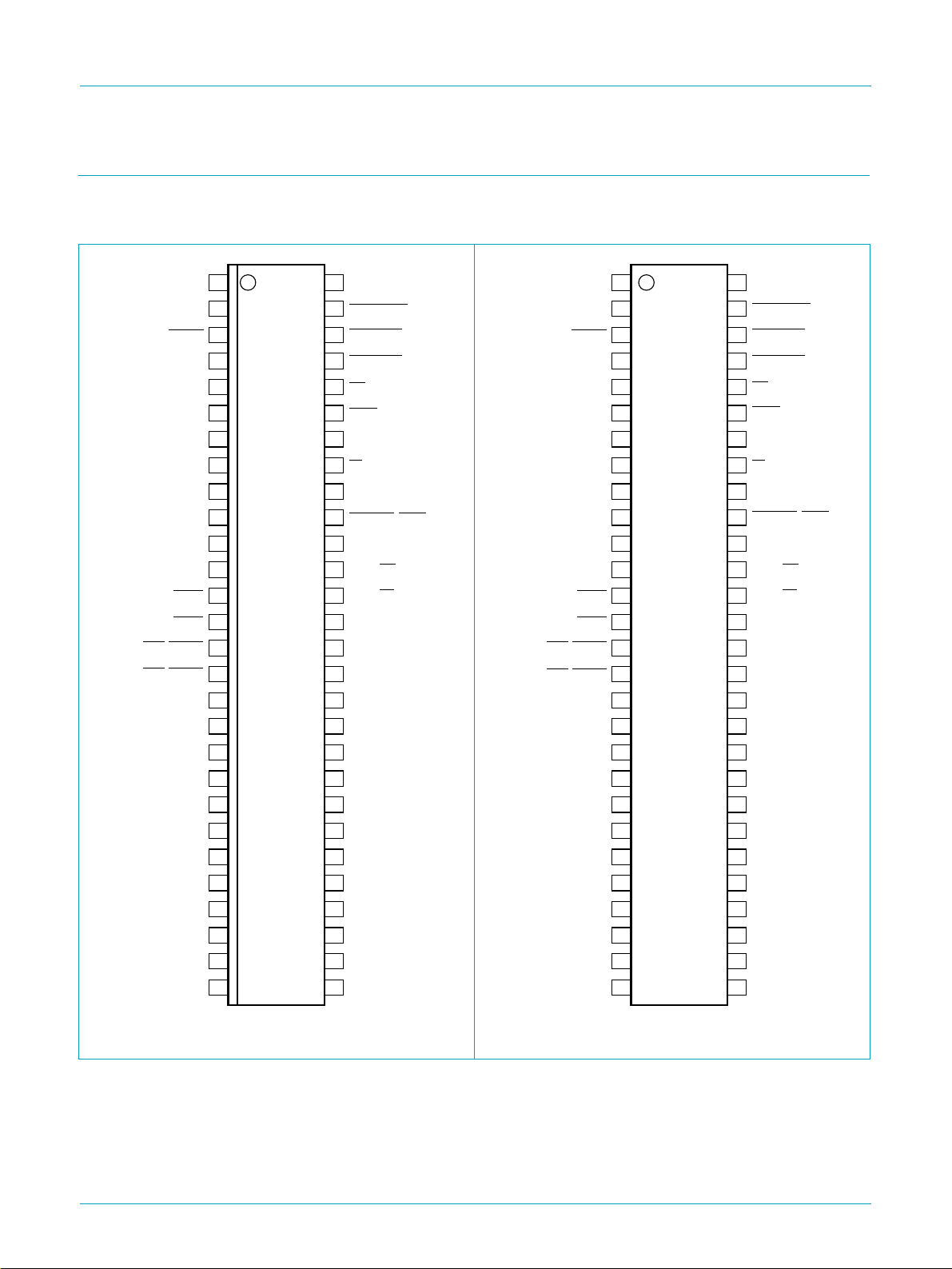
5. Pinning information
5.1 Pinning
ISP1130
USB compound hub with keyboard controller
handbook, halfpage
V
DN1_DM
DN1_DP
DN2_DM
DN2_DP
OC1/DPGL1
OC2/DPGL2
MX3/SCL
MX4/SDA
XTAL1
XTAL2
RESET
V
CC
GND
pu(3.3)
UP_DM
UP_DP
PSW1
PSW2
GND
MX0
MX1
MX2
MX5
MX6
MX7
MY0
MY1
MY2
1
2
3
4
5
6
7
8
9
10
11
12
13
14
15
16
17
18
19
20
21
22
23
24
25
26
27
28
ISP1130DL
MGS810
56
GND
55
CAPSLOCK
54
NUMLOCK
53
SCRLOCK
52
INT
51
PSEN
50
ALE
49
EA
SYNCLK
48
47
MEMSEL/UPGL
GND
46
45
MY17/WR
MY16/RD
44
MY15
43
MY14
42
MY13
41
MY12
40
MY11
39
MY10
38
MY9
37
MY8
36
MY7
35
MY6
34
MY5
33
MY4
32
MY3
31
V
30
reg(3.3)
GND
29
handbook, halfpage
OC1/DPGL1
OC2/DPGL2
MX4/SDA
XTAL1
XTAL2
RESET
V
CC
GND
V
pu(3.3)
UP_DM
UP_DP
DN1_DM
DN1_DP
DN2_DM
DN2_DP
PSW1
PSW2
GND
MX0
MX1
MX2
MX3/SCL
MX5
MX6
MX7
MY0
MY1
MY2
1
2
3
4
5
6
7
8
9
10
11
12
13
14
15
16
17
18
19
20
21
22
23
24
25
26
27
28
ISP1130N
MGS798
56
GND
55
CAPSLOCK
NUMLOCK
54
53
SCRLOCK
52
INT
PSEN
51
50
ALE
49
EA
SYNCLK
48
47
MEMSEL/UPGL
GND
46
45
MY17/WR
MY16/RD
44
MY15
43
MY14
42
MY13
41
MY12
40
MY11
39
MY10
38
MY9
37
MY8
36
MY7
35
MY6
34
MY5
33
MY4
32
MY3
31
V
30
reg(3.3)
GND
29
Fig 2. Pin configuration SSOP56. Fig 3. Pin configuration SDIP56.
9397 750 06895
Objective specification Rev. 01 — 23 March 2000 4 of 68
© Philips Electronics N.V. 2000. All rights reserved.

Philips Semiconductors
5.2 Pin description
Table 2: Pin description (SSOP56 and SDIP56)
Symbol
XTAL1 1 I crystal oscillator input (6 MHz)
XTAL2 2 O crystal oscillator output (6 MHz)
RESET 3 I reset input (Schmitt trigger); a LOW level produces an
V
CC
GND 5 - ground supply
V
pu(3.3)
UP_DM 7 AI/O upstream port D− connection (analog)
UP_DP 8 AI/O upstream port D+ connection (analog)
DN1_DM 9 AI/O downstream port 1 D− connection (analog)
DN1_DP 10 AI/O downstream port 1 D+ connection (analog)
DN2_DM 11 AI/O downstream port 2 D− connection (analog)
DN2_DP 12 AI/O downstream port 2 D+ connection (analog)
PSW1 13 O power switch control output for downstream port 1
PSW2 14 O power switch control output for downstream port 2
OC1/DPGL1 15 AI/O pin function is controlled via the USBCON register (see
OC2/DPGL2 16 AI/O pin function is controlled via the USBCON register (see
GND 17 - ground supply
MX0 18 I keyboard matrix return line (5 V tolerant, open drain)
MX1 19 I keyboard matrix return line (5 V tolerant, open drain)
[1]
ISP1130
USB compound hub with keyboard controller
Pin Type Description
asynchronous reset; connect to V
(internal POR circuit)
4 - supply voltage; connect to USB supply V
6 - regulated supply voltage (3.3 V ± 10%) from internal
regulator; used to connect pull-up resistor on UP_DP line;
pin function is controlled via the Device Status Register
(see Table 36):
Connect = 0 — V
Connect = 1 — V
floating (high impedance)
pu(3.3)
= 3.3 V
pu(3.3)
(open-drain)
(open-drain)
Table 53):
EnableOverCurrent = 0 — GoodLink LEDindicator output
for downstream port 1 (analog, open-drain); to connect an
LED use a 330 Ω series resistor
EnableOverCurrent = 1 — overcurrent sense input for
downstream port 1 (analog or digital); overcurrent sensing
can be either analog (AnalogOCDisable = 0) or digital
(AnalogOCDisable = 1)
Table 53):
EnableOverCurrent = 0 — GoodLink LEDindicator output
for downstream port 2 (analog, open-drain); to connect an
LED use a 330 Ω series resistor
EnableOverCurrent = 1 — overcurrent sense input for
downstream port 2 (analog or digital); overcurrent sensing
can be either analog (AnalogOCDIsable = 0) or digital
(AnalogOCDisable = 1)
for power-on reset
CC
BUS
[2]
[2]
9397 750 06895
Objective specification Rev. 01 — 23 March 2000 5 of 68
© Philips Electronics N.V. 2000. All rights reserved.

Philips Semiconductors
ISP1130
USB compound hub with keyboard controller
Table 2: Pin description (SSOP56 and SDIP56)
Symbol
[1]
Pin Type Description
…continued
MX2 20 I keyboard matrix return line (5 V tolerant, open drain)
MX3/SCL 21 I/O pin function is controlled via the I2C0CON register (see
Table 76):
ENS1 = 0 — keyboard matrix return line (5 V tolerant,
open drain)
[2]
ENS1 = 1 — I2C-bus clock output (5 V tolerant, open
[2]
drain)
MX4/SDA 22 I/O pin function is controlled via the I2C0CON register (see
Table 76):
ENS1 = 0 — keyboard matrix return line (5 V tolerant,
open drain)
[2]
ENS1 = 1 — bidirectional I2C-bus data line (5 V tolerant,
open drain)
MX5 23 I keyboard matrix return line(5 V tolerant, open drain)
[2]
[2]
MX6 24 I keyboard matrix return line (5 V tolerant, open drain)
MX7 25 I keyboard matrix return line (5 V tolerant, open drain)
MY0 26 I/O bidirectional keyboard matrix scan line (5 V tolerant)
MY1 27 I/O bidirectional keyboard matrix scan line (5 V tolerant)
MY2 28 I/O bidirectional keyboard matrix scan line (5 V tolerant)
GND 29 - ground supply
V
reg(3.3)
30 - regulated supply voltage (3.3 V ± 10%) from internal
regulator; used to supply external devices
MY3 31 I/O bidirectional keyboard matrix scan line (5 V tolerant)
MY4 32 I/O bidirectional keyboard matrix scan line (5 V tolerant)
MY5 33 I/O bidirectional keyboard matrix scan line (5 V tolerant)
MY6 34 I/O bidirectional keyboard matrix scan line (5 V tolerant)
MY7 35 I/O bidirectional keyboard matrix scan line (5 V tolerant)
MY8 36 I/O bidirectional keyboard matrix scan line (5 V tolerant)
MY9 37 I/O bidirectional keyboard matrix scan line (5 V tolerant)
MY10 38 I/O bidirectional keyboard matrix scan line (5 V tolerant)
MY11 39 I/O bidirectional keyboard matrix scan line (5 V tolerant)
MY12 40 I/O bidirectional keyboard matrix scan line (5 V tolerant)
MY13 41 I/O bidirectional keyboard matrix scan line (5 V tolerant)
MY14 42 I/O bidirectional keyboard matrix scan line (5 V tolerant)
MY15 43 I/O bidirectional keyboard matrix scan line (5 V tolerant)
MY16/RD 44 I/O bidirectional keyboard matrix scan line (5 V tolerant)
used as read strobe when accessing external memory
WR 45 I/O bidirectional keyboard matrix scan line (5 V tolerant)
MY17/
used as write strobe when accessing external memory
GND 46 - ground supply
[2]
[2]
[2]
[3]
[3]
[3]
[3]
[3]
[3]
[3]
[3]
[3]
[3]
[3]
[3]
[3]
[3]
[3]
[3]
[3]
;
[3]
;
9397 750 06895
Objective specification Rev. 01 — 23 March 2000 6 of 68
© Philips Electronics N.V. 2000. All rights reserved.

Philips Semiconductors
ISP1130
USB compound hub with keyboard controller
Table 2: Pin description (SSOP56 and SDIP56)
Symbol
MEMSEL/
UPGL
SYNCLK 48 O embedded microcontroller clock output; used for emulation
EA 49 I External Address enable input (internal pull-up); used to
ALE 50 O Address Latch Enable output; used to demultiplex AD0
PSEN 51 O Program Store ENable output; selects external memory for
INT 52 I external interrupt input (edge-triggered)
SCRLOCK 53 O control output for Scroll Lock LED (open-drain)
NUMLOCK 54 O control output for Num Lock LED (open-drain)
CAPSLOCK 55 O control output for Caps Lock LED (open-drain)
GND 56 - ground supply
[1] Symbol names with an overscore (e.g. NAME) indicate active LOW signals.
[2] MXn pins have an internal 8.2 kΩ pull-up resistor.
[3] MYn pins have an internal 82 kΩ pull-down resistor (keyboard matrix enabled) or an internal 8.2 kΩ
[1]
pull-up resistor (keyboardmatrix disabled).This is controlled by bit DisableKBDMatrix in the USBCON
register, see Table 53.
Pin Type Description
47 O pin function is controlled via the USBCON register (see
Table 53):
GL-MEMSELSelection = 0 — upstream port GoodLink
indicator output (open-drain)
GL-MEMSELSelection = 1 — chip select output for
external serial EEPROM (open-drain)
access external memory
during external memory access
program execution
…continued
6. Functional description
The ISP1130 is a compound USB hub with an integrated keyboard controller.It has 2
bus-powered downstream ports with 3 non-removable embedded functions, the first
of which is dedicated to the keyboard function. The downstream ports can be used to
connect low-speed or full-speed USB peripherals, such as a mouse, printer, another
keyboard or another hub. The block diagram is shown in Figure 1.
The embedded functions have no external hardware connections. They provide USB
endpoints for equipment functions implemented by a microcontroller. Each endpoint
has an associated FIFO buffer in the on-board RAM, which can be accessed by the
integrated microcontroller via memory mapped registers using special commands
(see Section 9).
An optional serial I2C-bus interface (see Section 11) is provided for external
EEPROM access, allowing the user to program the vendor ID, product ID or activate
the built-in keyboard matrix.
9397 750 06895
Objective specification Rev. 01 — 23 March 2000 7 of 68
© Philips Electronics N.V. 2000. All rights reserved.

Philips Semiconductors
6.1 80C51 microcontroller
An integrated 80C51 microcontroller serves as a keyboard controller. It has 8 kbytes
of mask ROM and 256 bytes of RAM. The I/O ports have been configured as an
8 × 18 line scan matrix. Three LED control outputs are available for keyboard status
indicators (Caps Lock, Num Lock and Scroll Lock). Interfacingto the USB hub is done
via 3 registers (command, data, status), which are accessible via the external data
memory address space (MOVX instruction).
The keyboard firmware resides in the ROM and enumerates the embedded function
as ‘HID compatible keyboard device’ during hub initialization.
The microcontroller runs on a 12 MHz clock, derived from the PLL oscillator. A
watchdog timer resets the microcontroller in case of a software hang-up.
6.2 Analog transceivers
The integrated transceivers interface directly to the USB cables through external
termination resistors. They are capable of transmitting and receiving serial data at
both ‘full-speed’ (12 Mbit/s) and ‘low-speed’ (1.5 Mbit/s) data rates. The slew rates
are adjusted according to the speed of the device connected and lie within the range
mentioned in the
USB compound hub with keyboard controller
USB Specification Rev. 1.1
ISP1130
.
6.3 Philips Serial Interface Engine (SIE)
The Philips SIE implements the full USB protocol layer. It is completely hardwired for
speed and needs no firmware intervention. The functions of this block include:
synchronization pattern recognition, parallel/serial conversion, bit (de-)stuffing, CRC
checking/generation, Packet IDentifier (PID) verification/generation, address
recognition, handshake evaluation/generation.
6.4 Hub repeater
The hub repeater is responsible for managing connectivity on a ‘per packet’ basis. It
implements ‘packet signalling’ and ‘resume’ connectivity. Low-speed devices can be
connected to downstream ports. If a low-speed device is detected the repeater will
not propagate upstream packetsto the corresponding port, unless they are preceded
by a PREAMBLE PID.
6.5 End-of-frame timers
This block contains the specified EOF1 and EOF2 timers which are used to detect
‘loss-of-activity’ and ‘babble’ error conditions in the hub repeater. The timers also
maintain the low-speed keep-alive strobe which is sent at the beginning of a frame.
6.6 General and individual port controller
The general and individual port controllers together provide status and control of
individual downstream ports. Any port status change will be reported to the host via
the hub status change (interrupt) endpoint.
9397 750 06895
Objective specification Rev. 01 — 23 March 2000 8 of 68
© Philips Electronics N.V. 2000. All rights reserved.
Philips Semiconductors
6.7 GoodLink
Indication of a good USB connection is provided through GoodLink technology. An
LED can be directly connected via an external 330 Ω resistor. The ISP1130 supports
GoodLink indication for the hub (upstream port) via output MEMSEL/UPGL and for
the two downstream ports via OCn/DPGLn, controlled via bits GL-MEMSELSelection
and EnableOverCurrent in the USBCON register (see Table 53).
During enumeration the LED blinks on momentarily. After successful configuration of
the ISP1130, the LED is permanently on. The hub GoodLink indicator blinks off for
approximately 128 ms when the hub receives a packet addressed to it. Downstream
GoodLink indicators blink upon an acknowledgment from the associated port. In
‘suspend’ mode the LED is off.
This feature provides a user-friendly indication of the status of the hub, the connected
downstream devices and the USB traffic. It is a useful diagnostics tool to isolate faulty
USB equipment and helps to reduce field support and hotline costs.
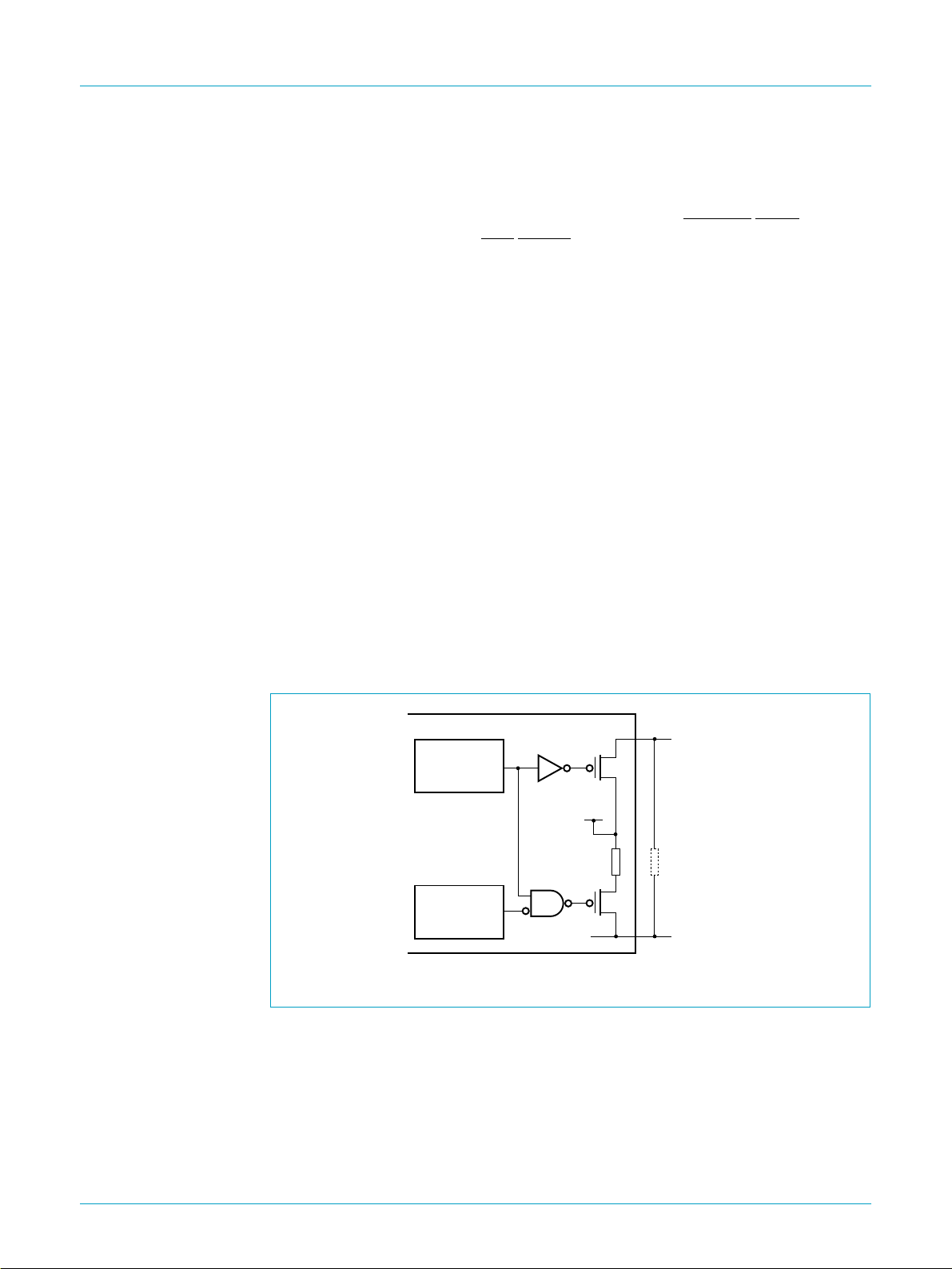
6.8 SoftConnect
The connection to the USB is accomplished by bringing D+ (for full-speed USB
devices) HIGH through a 1.5 kΩ pull-up resistor. In the ISP1130, the 1.5 kΩ pull-up
resistor is integrated on-chip and by default is disconnected from the +3.3 V supply.
ISP1130
USB compound hub with keyboard controller
The integrated microcontroller controls the connection of the internal resistor on D+ to
V
the Device Status register switches on V
via bit SoftConnect_N in the USBCON register (see Table 53). Bit Connect in
pu(3.3)
(defaultis off) to an alternative external
pu(3.3)
pull-up resistor. A functional schematic diagram is given in Figure 4.
dth
Connect
(Device Status
Register)
SoftConnect_N
(Configuration
Register)
Fig 4. SoftConnect control logic.
ISP1130
3.3 V
supply
1.5 kΩ
(internal
pull-up)
MGL920
V
pu(3.3)
1.5 kΩ
(external
pull-up)
UP_DP
This mechanism allows the microcontroller to complete its initialization sequence
before deciding to establish connection to the USB. Re-initialization of the USB
connection can also be performed without disconnecting the cable.
It should be noted that the tolerance of the internal resistors is higher (30%) than is
specified by the USB specification (5%). However, the overall VSE voltage
specification for the connection can still be met with good margin (see Table 92). The
decision to use this feature lies with the USB equipment designer.
9397 750 06895
Objective specification Rev. 01 — 23 March 2000 9 of 68
© Philips Electronics N.V. 2000. All rights reserved.

Philips Semiconductors
6.9 Bit clock recovery
The bit clock recovery circuit recovers the clock from the incoming USB data stream
using a 4× oversampling principle. It is able to track jitter and frequency drift as
specified by the
6.10 Voltage regulator
A 5 to 3.3 V DC-DC regulator is integrated on-chip to supply the analog transceiver
and internal logic. This can also be used to supply the terminal 1.5 kΩ pull-up resistor
on the D+ line of the upstream connection.
6.11 PLL clock multiplier
A 6 to 48 MHz clock multiplier Phase-Locked Loop (PLL) is integrated on-chip. This
allows for the use of low-cost 6 MHz crystals. The low crystal frequency also
minimizes Electro-Magnetic Interference (EMI). The PLL requires no external
components.
6.12 Overcurrent detection
USB compound hub with keyboard controller
USB Specification Rev. 1.1
ISP1130
.
An overcurrent detection circuit for downstream ports has been integrated on-chip. It
is self-reporting, resets automatically, has a low trip time and requires no external
components. The ISP1130 supports individual overcurrent detection.
6.13 Power-on reset
The ISP1130 has an internal power-on reset circuit, which generates a reset pulse
when the supply voltage is switched on and when the supply voltage drops below a
predetermined threshold value (see Table 89).
6.14 I2C-bus interface
A serial I2C-bus interface (single master or slave, bit rate up to 400 kHz) is provided
to read vendor ID,product ID and other configuration data from an external EEPROM
(e.g., Philips PCF8582 or equivalent). For more information, see Section 11.
The I2C-bus interface timing is programmable and complies with the standard mode
and the Fast mode of operation as described in
number 9398 393 40011.
The I2C-bus and how to use it
, order
9397 750 06895
Objective specification Rev. 01 — 23 March 2000 10 of 68
© Philips Electronics N.V. 2000. All rights reserved.

Philips Semiconductors
7. Endpoint descriptions
Each USB device is logically composed of several independent endpoints. An
endpoint acts as a terminus of a communication flow between the host and the
device. At design time each endpoint is assigned a unique number (endpoint
identifier, see Table 3). The combination of the device address (given by the host
during enumeration), the endpoint number and the transfer direction allows each
endpoint to be uniquely referenced.
7.1 Endpoint configuration
The ISP1130 hub has 1 to 2 downstream ports and 1 to 3 embedded functions. The
upstream and downstream ports are fully handled by hardware and require no
firmware intervention. Downstream port 2 can be disabled by connecting both D+ and
D− to VCC.
The number of embedded functions can be configured from 1 to 3 via the USBCONA
register. These embedded functions give access to the keyboardcontroller and other
optional software functions. The functions are assigned as follows:
ISP1130
USB compound hub with keyboard controller
Embedded function 1: standard keyboard
•
Embedded function 2:
•
– multimedia functions (e.g. volume control)
– ACPI system control
– application launch keys
Embedded function 3: user-defined functions.
•
Each embedded function has two endpoint types: endpoint 0 (control) and endpoint 1
(generic: bulk and/or interrupt). The embedded function endpoints can handle a
maximum of 8 bytes per transfer.
Table 3: Endpoint allocation
Function Ports Endpoint
0: upstream
Hub
Embedded
Function 1
Embedded
Function 2
[4]
1, 2
:
downstream
3 (or 2
4 (or 3
identifier
0 control -
1 interrupt -
[5]
) 0 control 0 OUT 8
1 generic
[5]
) 0 control 4 OUT 8
1 generic
Transfer
type
Endpoint
index
[2]
[2]
-
[2]
1IN8
[3]
2 OUT 8
3IN8
5IN8
[3]
6 OUT 8
7IN8
Direction
OUT 64
IN 64
IN 1
[1]
Max. packet
size (bytes)
9397 750 06895
Objective specification Rev. 01 — 23 March 2000 11 of 68
© Philips Electronics N.V. 2000. All rights reserved.

Philips Semiconductors
ISP1130
USB compound hub with keyboard controller
Table 3: Endpoint allocation
Function Ports Endpoint
Embedded
Function 3
[1] IN: input for the USB host; OUT: output from the USB host.
[2] Hub endpoints are not indexed.
[3] Generic endpoint can be used as bulk or interrupt endpoint.
[4] Port 2 can be disabled by connecting both D+ and D− to VCC.
[5] The port number is reduced by 1 when downstream port 2 is disabled.
5 (or 4
[5]
) 0 control 8 OUT 8
…continued
identifier
1 generic
Transfer
type
Endpoint
index
9IN8
[3]
10 OUT 8
11 IN 8
Direction
[1]
7.2 Hub endpoint 0 (control)
All USB devices and functions must implement a default control endpoint (ID = 0).
This endpoint is used by the host to configure the device and to perform generic USB
status and control access.
The ISP1130 hub supports the following USB descriptor information through its
control endpoint 0, which can handle transfers of 64 bytes maximum:
Device descriptor
•
Configuration descriptor
•
Interface descriptor
•
Endpoint descriptor
•
Hub descriptor
•
String descriptor.
•
Max. packet
size (bytes)
7.3 Hub endpoint 1 (interrupt)
Endpoint 1 is used by the ISP1130 hub to provide port status change information to
the host. This endpoint can be accessed only after the hub has been configured by
the host (by sending the Set Configuration command).
Endpoint 1 is an interrupt endpoint: the host polls it once every 255 ms by sending an
IN token. If the hub has detected no change in the port status it returns a NAK (Not
AcKnowledge) response to this request, otherwise it sends the Status Change byte
(see Table 4).
Table 4: Status Change byte: bit allocation
Bit Symbol Description
0 Hub SC a logic 1 indicates a status change on the hub’s upstream port
1 Port 1 SC a logic 1 indicates a status change on downstream port 1
2 Port 2 SC a logic 1 indicates a status change on downstream port 2 or on
embedded function 1 (downstream port 2 disabled)
3 Port 3 SC a logic 1 indicates a status change on embedded function 1 or on
embedded function 2 (downstream port 2 disabled)
9397 750 06895
Objective specification Rev. 01 — 23 March 2000 12 of 68
© Philips Electronics N.V. 2000. All rights reserved.

Philips Semiconductors
ISP1130
USB compound hub with keyboard controller
8. Host requests
8.1 Standard requests
Table 4: Status Change byte: bit allocation
Bit Symbol Description
4 Port 4 SC a logic 1 indicates a status change on embedded function 2 or on
embedded function 3 (downstream port 2 disabled)
5 Port 5 SC a logic 1 indicates a status change on embedded function 3; not used
if downstream port 2 is disabled
6 reserved not used
7 reserved not used
…continued
The ISP1130 handles all standard USB requests from the host via control endpoint 0.
The control endpoint can handle a maximum of 64 bytes per transfer.
Remark: Please note that the USB data transmission order is Least Significant Bit
(LSB) first. In the following tables multi-byte variables are displayed least significant
byte first.
Table 5 shows the supported standard USB requests. Some requests are explicitly
unsupported. All other requests will be responded with a STALL packet.
Table 5: Standard USB requests
Request name bmRequestType
Address
Set Address X000 0000 05 address
Configuration
Get Configuration 1000 0000 08 00, 00 00, 00 01, 00 configuration
Set Configuration (0) X000 0000 09 00, 00 00, 00 00, 00 none
Set Configuration (1) X000 0000 09 01, 00 00, 00 00, 00 none
Descriptor
Get Configuration
Descriptor
Get Device Descriptor 1000 0000 06 00, 01 00, 00 length
Get String Descriptor (0) 1000 0000 06 00, 03 00, 00 length
Get String Descriptor (1) 1000 0000 06 01, 03 09, 04 length
Get String Descriptor (2) 1000 0000 06 02, 03 09, 04 length
byte 0 [7:0]
(Bin)
1000 0000 06 00, 02 00, 00 length
bRequest
byte 1
(Hex)
wValue
byte 2, 3
(Hex)
wIndex
byte 4, 5
(Hex)
[1]
00, 00 00, 00 none
wLength
byte 6, 7
(Hex)
Data
value = 01H
[2]
[2]
[2]
[2]
[2]
configuration,
interface and
endpoint
descriptors
device
descriptor
language ID
string
manufacturer
string
product string
9397 750 06895
Objective specification Rev. 01 — 23 March 2000 13 of 68
© Philips Electronics N.V. 2000. All rights reserved.

Philips Semiconductors
ISP1130
USB compound hub with keyboard controller
Table 5: Standard USB requests
Request name bmRequestType
byte 0 [7:0]
(Bin)
…continued
bRequest
byte 1
(Hex)
wValue
byte 2, 3
(Hex)
wIndex
byte 4, 5
(Hex)
wLength
byte 6, 7
(Hex)
Data
Feature
Clear Device Feature
X000 0000 01 01, 00 00, 00 00, 00 none
(REMOTE_WAKEUP)
Clear Endpoint (1)
X000 0010 01 00, 00 81, 00 00, 00 none
Feature (HALT/STALL)
Set Device Feature
X000 0000 03 01, 00 00, 00 00, 00 none
(REMOTE_WAKEUP)
Set Endpoint (1)
X000 0010 03 00, 00 81, 00 00, 00 none
Feature (HALT/STALL)
Status
Get Device Status 1000 0000 00 00, 00 00, 00 02, 00 device status
Get Interface Status 1000 0001 00 00, 00 00, 00 02, 00 zero
Get Endpoint (0) Status 1000 0010 00 00, 00 00/80
[3]
, 00 02, 00 endpoint 0
status
Get Endpoint (1) Status 1000 0010 00 00, 00 81, 00 02, 00 endpoint 1
status
Unsupported
Set Descriptor 0000 0000 07 XX, XX XX, XX XX, XX descriptor;
STALL
Get Interface 1000 0001 0A 00, 00 XX, XX 01, 00 STALL
Set Interface X000 0001 0B XX, XX XX, XX 00, 00 STALL
Synch Frame 1000 0010 0C 00, 00 XX, XX 02, 00 STALL
[1] Device address: 0 to 127.
[2] Returned value in bytes.
[3] MSB specifies endpoint direction: 0 = OUT, 1= IN. The ISP1130 accepts either value.
8.2 Hub specific requests
In Table 6 the supported hub specific requests are listed, as well as some
unsupported requests. Table 7 provides the feature selectors for setting or clearing
port features.
Table 6: Hub specific requests
Request name bmRequestType
byte 0 [7:0]
(Bin)
Descriptor
Get Hub Descriptor 1010 0000 06 00, 00/29
Feature
Clear Hub Feature
X010 0000 01 00, 00 00, 00 00, 00 none
(C_LOCAL_POWER)
Clear Port Feature
X010 0011 01 feature
(feature selectors)
Set Port Feature
X010 0011 03 feature
(feature selectors)
bRequest
byte 1
(Hex)
wValue
byte 2, 3
(Hex)
wIndex
byte 4, 5
(Hex)
[1]
00, 00 length
[3]
, 00 port
[3]
, 00 port
wLength
byte 6, 7
(Hex)
[2]
, 00 hub descriptor
[4]
, 00 00, 00 none
[4]
, 00 00, 00 none
Data
9397 750 06895
Objective specification Rev. 01 — 23 March 2000 14 of 68
© Philips Electronics N.V. 2000. All rights reserved.

Philips Semiconductors
ISP1130
USB compound hub with keyboard controller
Table 6: Hub specific requests
Request name bmRequestType
…continued
byte 0 [7:0]
(Bin)
bRequest
byte 1
(Hex)
wValue
byte 2, 3
(Hex)
wIndex
byte 4, 5
(Hex)
wLength
byte 6, 7
(Hex)
Data
Status
Get Hub Status 1010 0000 00 00, 00 00, 00 04, 00 hubstatusand
status change
field
[4]
Get Port Status 1010 0011 00 00, 00 port
, 00 04, 00 port status
Unsupported
[4]
Get Bus Status 1010 0011 02 00, 00 port
Clear Hub Feature
X010 0000 01 01, 00 00, 00 00, 00 STALL
, 00 01, 00 STALL
(C_OVER_CURRENT)
Set Hub Descriptor X010 0000 07 XX, XX 00, 00 3E, 00 STALL
Set Hub Feature
X010 0000 03 00, 00 00, 00 00, 00 STALL
(C_LOCAL_POWER)
Set Hub Feature
X010 0000 03 01, 00 00, 00 00, 00 STALL
(C_OVER_CURRENT)
[1]
USB Specification Rev. 1.0
[2] Returned value in bytes.
[3] Feature selector value, see Table 7.
[4] Downstream port identifier: 1 to 5 (1, 2: downstream ports, 3 to 5: embedded functions 1 to 3). If downstream port 2 is disabled, the port
identifiers are 1 to 4 (1: downstream port, 2 to 4: embedded functions 1 to 3).
uses 00H,
USB Specification Rev. 1.1
specifies 29H.
Table 7: Port feature selectors
Feature selector name Value (Hex) Set feature Clear feature
PORT_CONNECTION 00 not used not used
PORT_ENABLE 01 not used disables a port
PORT_SUSPEND 02 suspends a port resumes a port
PORT_OVERCURRENT 03 not used not used
PORT_RESET 04 resets and enables
not used
a port
PORT_POWER 08 powers on a port powers off a port
PORT_LOW_SPEED 09 not used not used
C_PORT_CONNECTION 10 not used clears port connection
change bit
C_PORT_ENABLE 11 not used clears port enable
change bit
C_PORT_SUSPEND 12 not used clears port suspend
change bit
C_PORT_OVERCURRENT 13 not used clears port overcurrent
change bit
C_PORT_RESET 14 not used clears port reset
change bit
9397 750 06895
Objective specification Rev. 01 — 23 March 2000 15 of 68
© Philips Electronics N.V. 2000. All rights reserved.

Philips Semiconductors
8.3 Descriptors
The ISP1130 hub controller supports the following standard USB descriptors:
•
•
•
•
•
•
Table 8: Device descriptor
Values in square brackets are optional.
Offset
(bytes)
0 bLength 1 12 descriptor length = 18 bytes
1 bDescriptorType 1 01 type = DEVICE
2 bcdUSB 2 10, 01
4 bDeviceClass 1 09 HUB_CLASSCODE
5 bDeviceSubClass 1 00 6 bDeviceProtocol 1 00 7 bMaxPacketSize0 1 40 packet size = 64 bytes
8 idVendor 2 VID vendor ID; programmable via the Set
10 idProduct 2 PID product ID; programmable via the Set
12 bcdDevice 2 00,
14 iManufacturer 1 00 no manufacturer string (default)
15 iProduct 1 00 no product string (default)
16 iSerialNumber 1 00 no serial number string
17 bNumConfigurations 1 01 one configuration
Device
Configuration
Interface
Endpoint
Hub
String.
Field name Size
ISP1130
USB compound hub with keyboard controller
(bytes)
Value
(Hex)
XX
[01] manufacturer string enabled
[02] product string enabled
Comments
USB Specification Rev. 1.1
VID/PID command (see Table 43)
VID/PID command (see Table 43)
device release 1.0 (XX = 01H); silicon
[1]
revision increments this value
[2]
[2]
[1] XX represents the hardware setting DEVREV, which indicates the 8-bit device release number. This
value is incremented upon silicon revision.
[2] Controlled via bit StringDescriptorEnable in the Set Mode command (see Table 25).
Table 9: Configuration descriptor
Values in square brackets are optional.
Offset
(bytes)
0 bLength 1 09 descriptor length=9bytes
1 bDescriptorType 1 02 type = CONFIGURATION
2 wTotalLength 2 19, 00 total length of configuration, interface
4 bNumInterfaces 1 01 one interface
9397 750 06895
Objective specification Rev. 01 — 23 March 2000 16 of 68
Field name Size
(bytes)
Value
(Hex)
Comments
and endpoint descriptors (25 bytes)
© Philips Electronics N.V. 2000. All rights reserved.

Philips Semiconductors
ISP1130
USB compound hub with keyboard controller
Table 9: Configuration descriptor
…continued
Values in square brackets are optional.
Offset
(bytes)
Field name Size
(bytes)
Value
(Hex)
Comments
5 bConfigurationValue 1 01 configuration value = 1
6 iConfiguration 1 00 no configuration string
7 bmAttributes 1 A0 bus-powered with remote wake-up
(default)
[E0] hybrid-powered with remote wake-up;
configured via bit 7 in the USBCON
register (see Table 53)
8 MaxPower
[1] Value in units of 2 mA.
[1]
1 32 100 mA
Table 10: Interface descriptor
Offset
(bytes)
Field name Size
(bytes)
Value
(Hex)
Comments
0 bLength 1 09 descriptor length=9bytes
1 bDescriptorType 1 04 type = INTERFACE
2 bInterfaceNumber 1 00 3 bAlternateSetting 1 00 no alternate setting
4 bNumEndpoints 1 01 status change (interrupt) endpoint
5 bInterfaceClass 1 09 HUB_CLASSCODE
6 bInterfaceSubClass 1 00 7 bInterfaceProtocol 1 00 no class-specific protocol
8 bInterface 1 00 no interface string
Table 11: Endpoint descriptor
Offset
(bytes)
Field name Size
(bytes)
Value
(Hex)
Comments
0 bLength 1 07 descriptor length=7bytes
1 bDescriptorType 1 05 type = ENDPOINT
2 bEndpointAddress 1 81 endpoint 1, direction: IN
3 bmAttributes 1 03 interrupt endpoint
4 wMaxPacketSize 2 01, 00 packet size = 1 byte
6 bInterval 1 FF polling interval (255 ms)
Table 12: Hub descriptor
Offset
(bytes)
Field name Size
(bytes)
Value
(Hex)
Comments
0 bDescLength 1 09 descriptor length=9bytes
1 bDescriptorType 1 29 type = HUB
[2]
2 bNbrPorts 1 03
number of downstream ports (1 or 2;
default = 2) + number of embedded
functions (1 to 3; default = 1)
9397 750 06895
Objective specification Rev. 01 — 23 March 2000 17 of 68
© Philips Electronics N.V. 2000. All rights reserved.

Philips Semiconductors
ISP1130
USB compound hub with keyboard controller
Table 12: Hub descriptor
Offset
Field name Size
(bytes)
…continued
(bytes)
Value
(Hex)
Comments
3 wHubCharacteristics 2 0D, 00 individual power switching,
individual overcurrent protection
15, 00 individual power switching,
no overcurrent protection
[1]
5 bPwrOn2PwrGood
1 32 100 ms
6 bHubContrCurrent 1 64 maximum hub controller current
(100 mA)
[3]
7 DeviceRemovable 1 08
downstream ports removable;
embedded functions non-removable
8 PortPwrCtrlMask 1 FF must be all ones for compatibility with
USB Specification Rev. 1.0
[1] Value in units of 2 ms.
[2] Depending on the number of embedded functions configured, the value ranges from 03H to 05H or
from 02H to 04H (downstream port 2 disabled).
Remark: Downstream port 2 can be disabled by connecting both D+ and D− to VCC. Embedded
functions are configured via the USBCONA register (see Table 55).
[3] Default value (08H): ports 1 and 2 removable, port 3 non-removable. The value can be 08H, 18H or
38H depending on the configured number of embedded functions (1, 2 or 3). When downstream
port 2 is disabled, the possible values are 4CH, 0CH or 1CH (1, 2 or 3 embedded functions).
Table 13: String descriptors
String descriptors are optional and therefore disabled by default; they can be enabled via the
Set Mode command (see Table 25).
Offset
(bytes)
Field name Size
(bytes)
Value
(Hex)
Comments
String descriptor (0): language ID string
0 bLength 1 04 descriptor length=4bytes
1 bDescriptorType 1 03 type = STRING
2 bString 2 09, 04 LANGID code zero
String descriptor (1): manufacturer string
0 bLength 1 2E descriptor length = 46 bytes
1 bDescriptorType 1 03 type = STRING
[1]
2 bString 44 UC
“Philips Semiconductors”
String descriptor (2): product string
0 bLength 1 10 descriptor length = 16 bytes
1 bDescriptorType 1 03 type = STRING
[1]
2 bString 14 UC
[1] Unicode encoded string.
[2] X represents the hardware setting DEVNAME (4 bits), which specifies the final digit (X) in the device
name string “ISP113X”. The Unicode representation of this digit is “0000.0000.0011.DEVNAME”.
“ISP113X”
[2]
; X = 0H for the ISP1130
9397 750 06895
Objective specification Rev. 01 — 23 March 2000 18 of 68
© Philips Electronics N.V. 2000. All rights reserved.

Philips Semiconductors
8.4 Hub responses
This section describes the hub responses to requests from the USB host.
8.4.1 Get device status
The hub returns 2 bytes, see Table 14.
Table 14: Get device status response
Bit # Function Value Description
0 self-powered 0 bus-powered
1 remote wake-up 0 no remote wake-up
2 to 15 reserved 0 -
8.4.2 Get configuration
The hub returns 1 byte, see Table 15.
Table 15: Get configuration response
Bit # Function Value Description
0 configuration value 0 device not configured
1 to 7 reserved 0 -
ISP1130
USB compound hub with keyboard controller
1 hybrid-powered
1 remote wake-up enabled
1 device configured
8.4.3 Get interface status
The hub returns 2 bytes, see Table 16.
Table 16: Get interface status response
Bit # Function Value Description
0 to 15 reserved 0 -
8.4.4 Get hub status
The hub returns 4 bytes, see Table 17.
Table 17: Get hub status response
Bit # Function Value Description
0 local power source 0 local power supply good
1 overcurrent indicator 0 no overcurrent condition
2 to 15 reserved 0 16 local power status change 0 no change in local power status
17 overcurrent indicator change 0 no change in overcurrent condition
18 to 31 reserved 0 -
1 hub overcurrent condition detected
1 overcurrent condition changed
9397 750 06895
Objective specification Rev. 01 — 23 March 2000 19 of 68
© Philips Electronics N.V. 2000. All rights reserved.

Philips Semiconductors
8.4.5 Get port status
The hub returns 4 bytes. The first 2 bytes contain the port status bits (wPortStatus,
see Table 18). The last 2 bytes hold the port status change bits (wPortChange, see
Table 19).
Table 18: Get port status response (wPortStatus)
Bit # Function Value Description
0 current connect status 0 no device present
1 port enabled/disabled 0 port disabled
2 suspend 0 port not suspended
3 overcurrent indicator 0 no overcurrent condition
4 reset 0 reset not asserted
5 to 7 reserved 0 8 port power 0 port powered off
9 low-speed device attached 0 full-speed device attached
10 to 15 reserved 0 -
ISP1130
USB compound hub with keyboard controller
1 device present on this port
1 port enabled
1 port suspended
1 overcurrent condition detected
1 reset asserted
1 port power on
1 low-speed device attached
Table 19: Get port status response (wPortChange)
Bit # Function Value Description
0 connect status change 0 no change in current connect status
1 port enabled/disabled
change
2 suspend change 0 no change in suspend status
3 overcurrent indicator change 0 no change in overcurrent status
4 reset change 0 no change in reset status
5 to 15 reserved 0 -
8.4.6 Get configuration descriptor
The hub returns 25 bytes containing the configuration descriptor (9 bytes, see
Table 9), the interface descriptor (9 bytes, see Table 10) and the endpoint descriptor
(7 bytes, see Table 11).
8.4.7 Get device descriptor
The hub returns 18 bytes containing the device descriptor, see Table 8.
1 current connect status changed
0 no port error
1 port disabled by a port error
1 resume complete
1 overcurrent indicator changed
1 reset complete
9397 750 06895
Objective specification Rev. 01 — 23 March 2000 20 of 68
© Philips Electronics N.V. 2000. All rights reserved.

Philips Semiconductors
8.4.8 Get hub descriptor
The hub returns 9 bytes containing the hub descriptor, see Table 12.
8.4.9 Get string descriptor (0)
The hub returns 4 bytes containing the language ID, see Table 13.
8.4.10 Get string descriptor (1)
The hub returns 46 bytes containing the manufacturer name, see Table 13.
8.4.11 Get string descriptor (2)
The hub returns 16 bytes containing the product name, see Table 13.
ISP1130
USB compound hub with keyboard controller
9397 750 06895
Objective specification Rev. 01 — 23 March 2000 21 of 68
© Philips Electronics N.V. 2000. All rights reserved.
 Loading...