

Philips ISP1122A Datasheet

ISP1122A
Universal Serial Bus stand-alone hub
Rev. 01 — 27 March 2000 Preliminary specification
1. General description
The ISP1122A is a stand-alone Universal Serial Bus (USB) hub device which
complies with
(SIE), hub repeater, hub controller, USB data transceivers and a 3.3 V voltage
regulator. It has a configurable number of downstream ports, ranging from 2 to 5.
The ISP1122A can be bus-powered, self-powered or hybrid-powered. When it is
hybrid-poweredthe hub functions are poweredby the upstream power supply (V
but the downstream ports are powered by an external 5 Volt supply. The low power
consumption in ‘suspend’ mode allows easy design of equipment that is compliant
with the ACPI™, OnNow™ and USB power management requirements.
USB Specification Rev. 1.1
. It integrates a Serial Interface Engine
BUS
),
2. Features
The ISP1122A has built-in overcurrent sense inputs, supporting individual and global
overcurrent protection for downstream ports. All ports (including the hub) have
GoodLink™ indicator outputs foreasy visual monitoring of USB traffic. The ISP1122A
has a serial I2C-bus interface for external EEPROM access and a reduced frequency
(6 MHz) crystal oscillator. These features allow significant cost savings in system
design and easy implementation of advanced USB functionality into PC peripherals.
c
c
■ High performance USB hub device with integrated hub repeater, hub controller,
Serial Interface Engine (SIE), data transceivers and 3.3 V voltage regulator
■ Complies with
USB power management requirements
■ Configurable from 2 to 5 downstream ports with automatic speed detection
■ Internal power-on reset and low voltage reset circuit
■ Supports bus-powered, hybrid-powered and self-powered application
■ Individual or ganged power switching for downstream ports
■ Individual or global port overcurrent protection with built-in sense circuits
■ 6 MHz crystal oscillator with on-chip PLL for low EMI
■ Visual USB traffic monitoring (GoodLink™) for hub and downstream ports
■ I2C-bus interface to read vendor ID, product ID and configuration bits from
external EEPROM
■ Operation over the extended USB bus voltage range (4.0 to 5.5 V)
■ Operating temperature range −40 to +85 °C
■ 8 kV in-circuit ESD protection for lower cost of external components
Universal Serial Bus Specification Rev. 1.1
and ACPI, OnNow and
Philips Semiconductors
e
ISP1122A
USB stand-alone hub
■ Full-scan design with high test coverage
■ Available in 32-pin SDIP, SO and LQFP packages.
3. Ordering information
Table 1: Ordering information
Type number Package
Name Description Version
ISP1122AD SO32 plastic small outline package; 32 leads; body width 7.5 mm SOT287-1
ISP1122ANB SDIP32 plastic shrink dual in-line package; 32 leads (400 mil) SOT232-1
ISP1122ABD LQFP32 plastic low profile quad flat package; 32 leads; body 7 x 7 x 1.4 mm SOT358-1
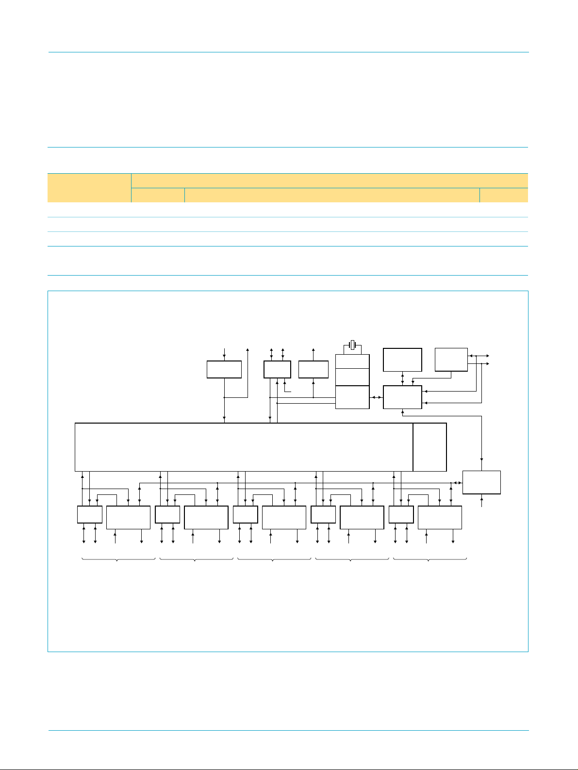
4. Block diagram
width
ANALOG
Tx/Rx
POWER SWITCH/
OC DETECT
D+ D− overcurrent
detection
downstream
port 1
ISP1122A
GoodLink/
power switch
LED/
ANALOG
Tx/Rx
POWER SWITCH/
OC DETECT
D+ D− overcurrent
detection
downstream
port 2
REGULATOR
GoodLink/
power switch
V
CC
SUPPLY
LED/
5 V
3.3 V
upstream
V
reg(3.3)
ANALOG
HUB
REPEATER
ANALOG
Tx/Rx
POWER SWITCH/
D+ D− overcurrent
detection
downstream
port 3
port
D+ D−
Tx/Rx
GoodLink/
OC DETECT
power switch
full
speed
LED/
GoodLink
LED
HUB
BIT CLOCK
RECOVERY
ANALOG
Tx/Rx
D+ D− overcurrent
detection
downstream
6 MHz
PLL
PHILIPS
SIE
GoodLink/
POWER SWITCH/
OC DETECT
LED/
power switch
port 4
PACKET
GENERATOR
HUB
CONTROLLER
ANALOG
Tx/Rx
D+ D− overcurrent
detection
downstream
I2C-BUS
INTERFACE
INDV
OPTION
END OF
FRAME
TIMERS
GoodLink/
POWER SWITCH/
OC DETECT
LED/
power switch
port 5
SDA
SCL
GENERAL
PORT
CONTROLLER
self/bus
powered
MBL169
This is a conceptual block diagram and does not include each individual signal.
Fig 1. Block diagram.
9397 750 06986
Preliminary specification Rev. 01 — 27 March 2000 2 of 48
© Philips Electronics N.V. 2000. All rights reserved.
Philips Semiconductors
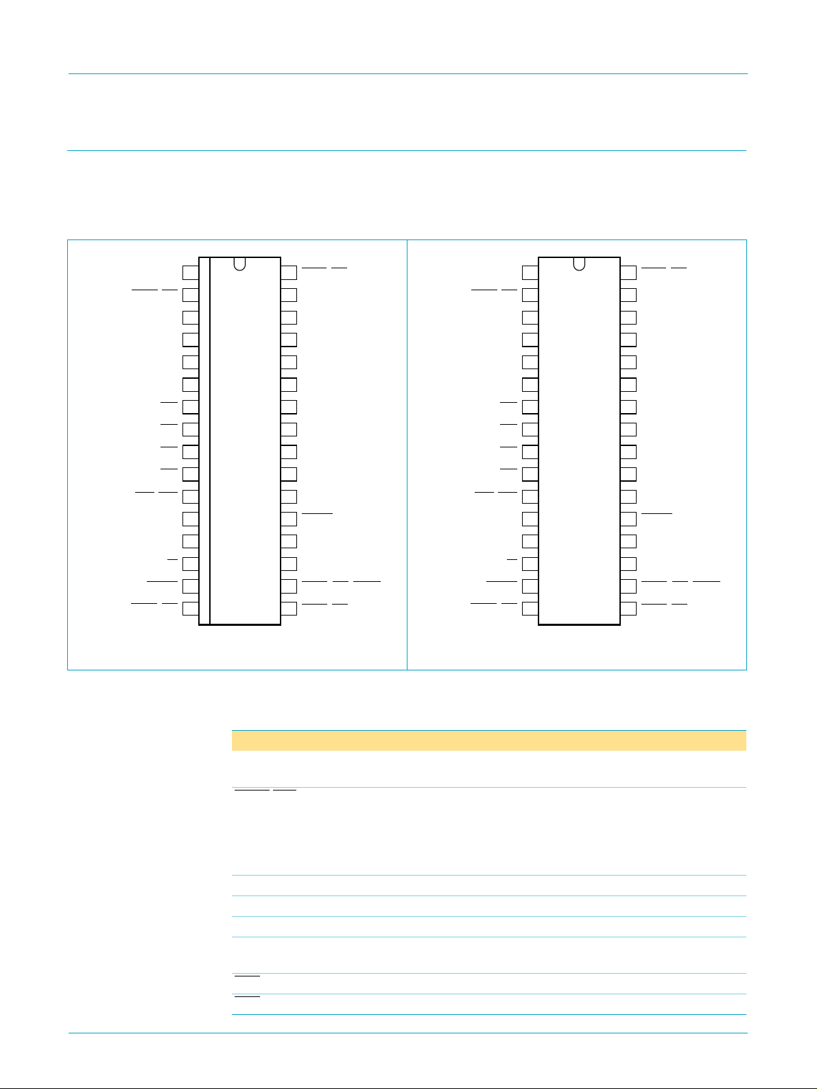
5. Pinning information
5.1 ISP1122AD (SO32) and ISP1122ANB (SDIP32)
5.1.1 Pinning
ISP1122A
USB stand-alone hub
handbook, halfpage
V
PSW2/GL2
OC5/GOC
reg(3.3)
GND
DM3
DP3
V
CC
OC1
OC2
OC3
OC4
DM4
DP4
SP/BP
HUBGL
1
2
3
4
5
6
7
8
9
10
11
12
13
14
15
16
ISP1122AD
MBL163
32
PSW1/GL1
DP2
31
DM2
30
DP0
29
DM0
28
DP1
27
DM1
26
DP5
25
DM5
24
INDV/SDA
23
OPTION/SCL
22
21
RESET
XTAL2
20
XTAL1
19
18
PSW5/GL5/GPSW
17
PSW4/GL4PSW3/GL3
handbook, halfpage
V
PSW2/GL2
OC5/GOC
reg(3.3)
GND
DM3
DP3
V
CC
OC1
OC2
OC3
OC4
DM4
DP4
SP/BP
HUBGL
1
2
3
4
5
6
7
8
ISP1122ANB
9
10
11
12
13
14
15
16
MBL164
Fig 2. Pin configuration SO32. Fig 3. Pin configuration SDIP32.
32
PSW1/GL1
DP2
31
DM2
30
DP0
29
DM0
28
DP1
27
DM1
26
DP5
25
DM5
24
INDV/SDA
23
OPTION/SCL
22
21
RESET
XTAL2
20
XTAL1
19
18
PSW5/GL5/GPSW
17
PSW4/GL4PSW3/GL3
5.1.2 Pin description
Table 2: Pin description for SO32 and SDIP32
reg(3.3)
CC
[1]
[2]
Pin Type Description
1 - regulated supply voltage (3.3 V ± 10%) from internal
regulator; used to connect pull-up resistor on DP0 line
[3]
2Omodes 4 to 6: power switch control output for downstream
port 2 (open-drain, 6 mA)
modes 0 to 3, 7: GoodLink LED indicator output for
downstream port 2 (open-drain, 6 mA); to connect an LED
use a 330 Ω series resistor
[4]
[4]
6 - supply voltage; connect to USB supply V
hybrid-powered) or to local supply V
DD
(bus-poweredor
BUS
(self-powered)
[5]
)
[5]
)
© Philips Electronics N.V. 2000. All rights reserved.
Symbol
V
PSW2/GL2
GND 3 - ground supply
DM3 4 AI/O downstream port 3 D− connection (analog)
DP3 5 AI/O downstream port 3 D+ connection (analog)
V
OC1 7 AI/I overcurrent sense input for downstream port 1 (analog
OC2 8 AI/I overcurrent sense input for downstream port 2 (analog
9397 750 06986
Preliminary specification Rev. 01 — 27 March 2000 3 of 48

Philips Semiconductors
ISP1122A
USB stand-alone hub
Table 2: Pin description for SO32 and SDIP32
Symbol
[1]
Pin Type Description
OC3 9 AI/I overcurrent sense input for downstream port 3 (analog
OC4 10 AI/I overcurrent sense input for downstream port 4 (analog
OC5/GOC
[3]
11 AI/I modes 5, 7: overcurrent sense input for downstream port 5
(analog
[5]
)
modes 0, 1, 3: global overcurrent sense input (analog
DM4 12 AI/O downstream port 4 D− connection (analog)
DP4 13 AI/O downstream port 4 D+ connection (analog)
…continued
[5]
[5]
[5]
[4]
[4]
SP/BP 14 I selects power mode:
self-powered: connect to V
(local power supply); also use
DD
this mode for hybrid-powered operation
bus-powered:connect to GND; disable downstream port 5 to
meet supply current requirements
[4]
HUBGL 15 O hub GoodLink LED indicator output (open-drain, 6 mA);
to connect an LED use a 330 Ω series resistor; if unused
via a 10 kΩ resistor
CC
PSW3/GL3
connect to V
[3]
16 O modes 4 to 6: power switch control output for downstream
port 3 (open-drain, 6 mA)
modes 0 to 3, 7: GoodLink LED indicator output for
downstream port 3 (open-drain, 6 mA); to connect an LED
use a 330 Ω series resistor
PSW4/GL4
[3]
17 O modes 4 to 6: power switch control output for downstream
port 4 (open-drain, 6 mA)
modes 0 to 3, 7: GoodLink LED indicator output for
downstream port 4 (open-drain, 6 mA); to connect an LED
use a 330 Ω series resistor
PSW5/GL5/
[3]
GPSW
18 O mode 5: power switch control output for downstream port 5
(open-drain, 6 mA)
modes 3, 7: GoodLink LED indicator output for downstream
port 5 (open-drain, 6 mA); to connect an LED use a 330 Ω
series resistor
modes 0 to 2: gang mode power switch control output
(open-drain, 6 mA)
XTAL1 19 I crystal oscillator input (6 MHz)
XTAL2 20 O crystal oscillator output (6 MHz)
RESET
[2]
21 I reset input (Schmitt trigger); a LOW level produces an
asynchronous reset; connect to V
for power-on reset
CC
(internal POR circuit)
2
OPTION/SCL 22 I/O mode selection input; also functions as I
C-bus clock output
(open-drain, 6 mA)
INDV/SDA 23 I/O selects individual (HIGH) or global (LOW) power switching
and overcurrent detection; also functions as bidirectional
2
C-bus data line (open-drain, 6 mA)
I
DM5 24 AI/O downstream port 5 D− connection (analog)
DP5 25 AI/O downstream port 5 D+ connection (analog)
DM1 26 AI/O downstream port 1 D− connection (analog)
DP1 27 AI/O downstream port 1 D+ connection (analog)
[4]
[4]
[6]
[6]
)
)
)
9397 750 06986
Preliminary specification Rev. 01 — 27 March 2000 4 of 48
© Philips Electronics N.V. 2000. All rights reserved.

Philips Semiconductors
ISP1122A
USB stand-alone hub
Table 2: Pin description for SO32 and SDIP32
Symbol
[1]
Pin Type Description
…continued
DM0 28 AI/O upstream port D− connection (analog)
DP0 29 AI/O upstream port D+ connection (analog)
DM2 30 AI/O downstream port 2 D− connection (analog)
DP2 31 AI/O downstream port 2 D+ connection (analog)
PSW1/GL1
[3]
32 O modes 4 to 6: power switch control output for downstream
[6]
[6]
port 1 (open-drain, 6 mA)
modes 0 to 3, 7: GoodLink LED indicator output for
downstream port 1 (open-drain, 6 mA); to connect an LED
use a 330 Ω series resistor
[1] Symbol names with an overscore (e.g. NAME) indicate active LOW signals.
[2] The voltage at pin V
connecting RESET to V
[3] See Table 4 “Mode selection”.
[4] To disable a downstream port connect both D+ and D− to VCCvia a 1 MΩ resistor; unused ports must
be disabled in reverse order starting from port 5.
[5] Analog detection circuit can be switched off using an external EEPROM, see Table 23; in this case,
the pin functions as a logic input (TTL level).
[6] Downstream ports 1 and 2 cannot be disabled.
is gated by the RESET pin. This allows fully self-powered operation by
reg(3.3)
(+5 V USB supply). If V
BUS
is lost upstream port D+ will not be driven.
BUS
9397 750 06986
Preliminary specification Rev. 01 — 27 March 2000 5 of 48
© Philips Electronics N.V. 2000. All rights reserved.
Philips Semiconductors
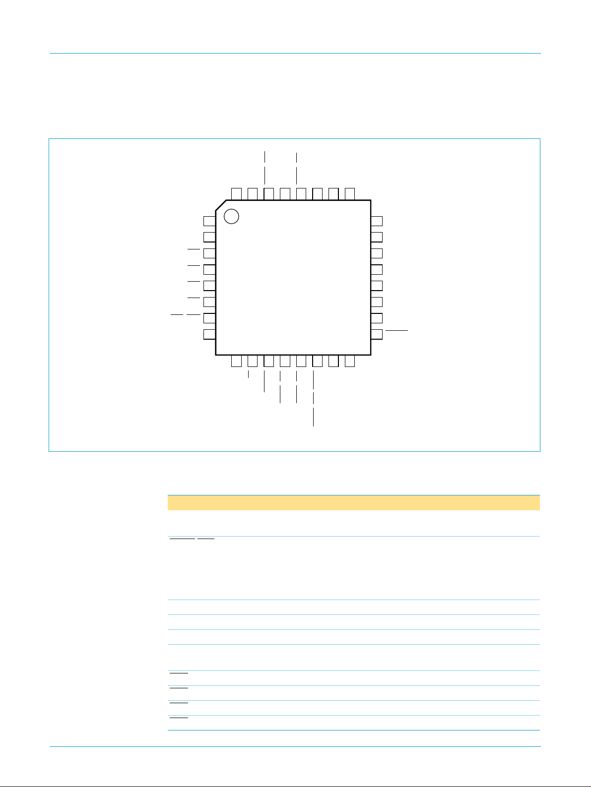
5.2 ISP1122ABD (LQFP32)
5.2.1 Pinning
handbook, full pagewidth
ISP1122A
USB stand-alone hub
DP3
V
OC1
OC2
OC3
OC4
OC5/GOC
DM4
Fig 4. Pin configuration LQFP32.
CC
DM3
GND
32
31
1
2
3
4
5
6
7
8
9
10
DP4
SP/BP
reg(3.3)
PSW2/GL2
V
PSW1/GL1
30
29
28
ISP1122ABD
11
12
13
HUBGL
PSW3/GL3
PSW4/GL4
DP2
DM2
DP0
27
26
25
14
15
16
MBL165
XTAL1
XTAL2
PSW5/GL5/GPSW
DM0
24
DP1
23
DM1
22
DP5
21
DM5
20
INDV/SDA
19
OPTION/SCL
18
RESET
17
5.2.2 Pin description
Table 3: Pin description for LQFP32
reg(3.3)
CC
[1]
[2]
Pin Type Description
29 - regulated supply voltage (3.3 V ± 10%) from internal
regulator; used to connect pull-up resistor on DP0 line
[3]
30 O modes 4 to 6: power switch control output for downstream
port 2 (open-drain, 6 mA)
modes 0 to 3, 7: GoodLink LED indicator output for
downstream port 2 (open-drain, 6 mA); to connect an LED
use a 330 Ω series resistor
[4]
[4]
2 - supply voltage; connect to USB supply V
hybrid-powered) or to local supply V
DD
(bus-poweredor
BUS
(self-powered)
[5]
)
[5]
)
[5]
)
[5]
)
© Philips Electronics N.V. 2000. All rights reserved.
Symbol
V
PSW2/GL2
GND 31 - ground supply
DM3 32 AI/O downstream port 3 D− connection (analog)
DP3 1 AI/O downstream port 3 D+ connection (analog)
V
OC1 3 AI/I overcurrent sense input for downstream port 1 (analog
OC2 4 AI/I overcurrent sense input for downstream port 2 (analog
OC3 5 AI/I overcurrent sense input for downstream port 3 (analog
OC4 6 AI/I overcurrent sense input for downstream port 4 (analog
9397 750 06986
Preliminary specification Rev. 01 — 27 March 2000 6 of 48

Philips Semiconductors
ISP1122A
USB stand-alone hub
Table 3: Pin description for LQFP32
Symbol
OC5/GOC
[1]
Pin Type Description
[3]
7 AI/I modes 5, 7: overcurrent sense input for downstream port 5
(analog
modes 0, 1, 3: global overcurrent sense input (analog
DM4 8 AI/O downstream port 4 D− connection (analog)
DP4 9 AI/O downstream port 4 D+ connection (analog)
…continued
[5]
)
[5]
[4]
[4]
SP/BP 10 I selects power mode:
self-powered: connect to V
(local power supply); also use
DD
this mode for hybrid-powered operation
bus-powered:connect to GND; disable downstream port 5 to
meet supply current requirements
[4]
HUBGL 11 O hub GoodLink LED indicator output (open-drain, 6 mA);
to connect an LED use a 330 Ω series resistor; if unused
via a 10 kΩ resistor
CC
PSW3/GL3
connect to V
[3]
12 O modes 4 to 6: power switch control output for downstream
port 3 (open-drain, 6 mA)
modes 0 to 3, 7: GoodLink LED indicator output for
downstream port 3 (open-drain, 6 mA); to connect an LED
use a 330 Ω series resistor
PSW4/GL4
[3]
13 O modes 4 to 6: power switch control output for downstream
port 4 (open-drain, 6 mA)
modes 0 to 3, 7: GoodLink LED indicator output for
downstream port 4 (open-drain, 6 mA); to connect an LED
use a 330 Ω series resistor
PSW5/GL5/
[3]
GPSW
14 O mode 5: power switch control output for downstream port 5
(open-drain, 6 mA)
modes 3, 7: GoodLink LED indicator output for downstream
port 5 (open-drain, 6 mA); to connect an LED use a 330 Ω
series resistor
modes 0 to 2: gang mode power switch control output
(open-drain, 6 mA)
XTAL1 15 I crystal oscillator input (6 MHz)
XTAL2 16 O crystal oscillator output (6 MHz)
RESET
[2]
17 I reset input (Schmitt trigger); a LOW level produces an
asynchronous reset; connect to V
for power-on reset
CC
(internal POR circuit)
2
OPTION/SCL 18 I/O mode selection input; also functions as I
C-bus clock output
(open-drain, 6 mA)
INDV/SDA 19 I/O selects individual (HIGH) or global (LOW) power switching
and overcurrent detection; also functions as bidirectional
2
C-bus data line (open-drain, 6 mA)
I
DM5 20 AI/O downstream port 5 D− connection (analog)
DP5 21 AI/O downstream port 5 D+ connection (analog)
DM1 22 AI/O downstream port 1 D− connection (analog)
DP1 23 AI/O downstream port 1 D+ connection (analog)
[4]
[4]
[6]
[6]
DM0 24 AI/O upstream port D− connection (analog)
DP0 25 AI/O upstream port D+ connection (analog)
)
9397 750 06986
Preliminary specification Rev. 01 — 27 March 2000 7 of 48
© Philips Electronics N.V. 2000. All rights reserved.

Philips Semiconductors
ISP1122A
USB stand-alone hub
Table 3: Pin description for LQFP32
Symbol
DM2 26 AI/O downstream port 2 D− connection (analog)
DP2 27 AI/O downstream port 2 D+ connection (analog)
PSW1/GL1
[1] Symbol names with an overscore (e.g. NAME) indicate active LOW signals.
[2] The voltage at pin V
[3] See Table 4 “Mode selection”.
[4] To disable a downstream port connect both D+ and D− to VCCvia a 1 MΩ resistor; unused ports must
[5] Analog detection circuit can be switched off using an external EEPROM, see Table 23; in this case,
[6] Downstream ports 1 and 2 cannot be disabled.
[1]
connecting RESET to V
be disabled in reverse order starting from port 5.
the pin functions as a logic input (TTL level).
6. Functional description
The ISP1122A is a stand-alone USB hub with up to 5 downstream ports. The number
of ports can be configured between 2 and 5. The downstream ports can be used to
connect low-speed or full-speed USB peripherals. All standard USB requests from
the host are handled by the hardware without the need for firmware intervention. The
block diagram is shown in Figure 1.
…continued
Pin Type Description
[6]
[6]
[3]
28 O modes 4 to 6: power switch control output for downstream
port 1 (open-drain, 6 mA)
modes 0 to 3, 7: GoodLink LED indicator output for
downstream port 1 (open-drain, 6 mA); to connect an LED
use a 330 Ω series resistor
is gated by the RESET pin. This allows fully self-powered operation by
reg(3.3)
(+5 V USB supply). If V
BUS
is lost upstream port D+ will not be driven.
BUS
The ISP1122A requires only a single supply voltage. An internal 3.3 V regulator
provides the supply voltage for the analog USB data transceivers.
The ISP1122A supports both bus-powered and self-powered hub operation. When
using bus-powered operation a downstream port cannot supply more than 100 mA to
a peripheral. In case of self-powered operation an external supply is used to power
the downstream ports, allowing a current consumption of max. 500 mA per port.
A basic I2C-bus interface is provided for reading vendor ID, product ID and
configuration bits from an external EEPROM upon a reset.
6.1 Analog transceivers
The integrated transceiver interfaces directly to the USB cables through external
termination resistors. They are capable of transmitting and receiving serial data at
both ‘full-speed’ (12 Mbit/s) and ‘low-speed’ (1.5 Mbit/s) data rates. The slew rates
are adjusted according to the speed of the device connected and lie within the range
mentioned in the
USB Specification Rev. 1.1
.
9397 750 06986
Preliminary specification Rev. 01 — 27 March 2000 8 of 48
© Philips Electronics N.V. 2000. All rights reserved.

Philips Semiconductors
6.2 Philips Serial Interface Engine (SIE)
The Philips SIE implements the full USB protocol layer. It is completely hardwired for
speed and needs no firmware intervention. The functions of this block include:
synchronization pattern recognition, parallel/serial conversion, bit (de-)stuffing, CRC
checking/generation, Packet IDentifier (PID) verification/generation, address
recognition, handshake evaluation/generation.
6.3 Hub repeater
The hub repeater is responsible for managing connectivity on a ‘per packet’ basis. It
implements ‘packet signalling’ and ‘resume’ connectivity. Low-speed devices can be
connected to downstream ports. If a low-speed device is detected the repeater will
not propagate upstream packets to the corresponding port, unless they are preceded
by a PREAMBLE PID.
6.4 End-of-frame timers
This block contains the specified EOF1 and EOF2 timers which are used to detect
‘loss-of-activity’ and ‘babble’ error conditions in the hub repeater. The timers also
maintain the low-speed keep-alive strobe which is sent at the beginning of a frame.
ISP1122A
USB stand-alone hub
6.5 General and individual port controller
The general and individual port controllers together provide status and control of
individual downstream ports. Any port status change will be reported to the host via
the hub status change (interrupt) endpoint.
6.6 GoodLink
Indication of a good USB connection is provided through GoodLink technology. An
LED can be directly connected via an external 330 Ω resistor.
During enumeration the LED blinks on momentarily. After successful configuration of
the ISP1122A, the LED is permanently on. The LED blinks off for 100 ms upon each
successful packet transfer (with ACK). The hub GoodLink indicator blinks when the
hub receives a packet addressed to it. Downstream GoodLink indicators blink upon
an acknowledgment from the associated port. In ‘suspend’ mode the LED is off.
This feature provides a user-friendly indication of the status of the hub, the connected
downstream devices and the USB traffic. It is a useful diagnostics tool to isolate faulty
USB equipment and helps to reduce field support and hotline costs.
6.7 Bit clock recovery
The bit clock recovery circuit recovers the clock from the incoming USB data stream
using a 4× oversampling principle. It is able to track jitter and frequency drift as
specified by the
USB Specification Rev. 1.1
.
6.8 Voltage regulator
A 5 to 3.3 V DC-DC regulator is integrated on-chip to supply the analog transceiver
and internal logic. This can also be used to supply the terminal 1.5 kΩ pull-up resistor
on the D+ line of the upstream connection.
9397 750 06986
Preliminary specification Rev. 01 — 27 March 2000 9 of 48
© Philips Electronics N.V. 2000. All rights reserved.

Philips Semiconductors
6.9 PLL clock multiplier
A 6 to 48 MHz clock multiplier Phase-Locked Loop (PLL) is integrated on-chip. This
allows for the use of low-cost 6 MHz crystals. The low crystal frequency also
minimizes Electro-Magnetic Interference (EMI). The PLL requires no external
components.
6.10 Overcurrent detection
An overcurrent detection circuit for downstream ports has been integrated on-chip. It
is self-reporting, resets automatically, has a low trip time and requires no external
components. Both individual and global overcurrent detection are supported.
6.11 I2C-bus interface
A basic serial I2C-bus interface (single master, 100 kHz) is provided to read VID, PID
and configuration bits from an external I2C-bus EEPROM (e.g. Philips PCF8582 or
equivalent). At reset the ISP1122A reads 6 bytes of data from the external memory.
The I2C-bus interface timing complies with the standard mode of operation as
described in
The I2C-bus and how to use it
ISP1122A
USB stand-alone hub
, order number 9398 393 40011.
7. Modes of operation
The ISP1122A has several modes of operation, each corresponding with a different
pin configuration. Modes are selected by means of pins INDV, OPTION and SP/BP,
as shown in Table 4.
Table 4: Mode selection
Mode INDV
0000GoodLink ganged power inactive global overcurrent
1001GoodLink ganged power inactive global overcurrent
2010GoodLink ganged power inactive
3011GoodLink
4100individual power inactive individual
5101individual power individual power individual
6110individual power inactive inactive
7111GoodLink
[1] Port power switching: logic 0 = ganged, logic 1 = individual.
[2] Power mode: logic0=bus-powered, logic1 = self-powered (or hybrid-powered).
[3] No overcurrent detection.
[4] No power switching.
[1]
OPTION SP/BP
[2]
PSWn/GLn
(n = 1 to 4)
PSW5/GL5/GPSW OCn
[4]
[4]
GoodLink
GoodLink
[4]
[4]
(n = 1 to 4)
[3]
inactive global overcurrent
overcurrent
overcurrent
[3]
individual
overcurrent
OC5/GOC
inactive
inactive
individual
overcurrent
inactive
individual
overcurrent
[3]
[3]
9397 750 06986
Preliminary specification Rev. 01 — 27 March 2000 10 of 48
© Philips Electronics N.V. 2000. All rights reserved.

Philips Semiconductors
8. Endpoint descriptions
Each USB device is logically composed of several independent endpoints. An
endpoint acts as a terminus of a communication flow between the host and the
device. At design time each endpoint is assigned a unique number (endpoint
identifier, see Table 5). The combination of the device address (given by the host
during enumeration), the endpoint number and the transfer direction allows each
endpoint to be uniquely referenced.
The ISP1122A has two endpoints, endpoint 0 (control) and endpoint 1 (interrupt).
Table 5: Hub endpoints
Function Ports Endpoint
Hub
[1] IN: input for the USB host; OUT: output from the USB host.
0: upstream
1 to 5: downstream
ISP1122A
USB stand-alone hub
identifier
0 control
1 interrupt IN 1
Transfer
type
Direction
OUT 64
IN 64
[1]
Max. packet
size (bytes)
8.1 Hub endpoint 0 (control)
All USB devices and functions must implement a default control endpoint (ID = 0).
This endpoint is used by the host to configure the device and to perform generic USB
status and control access.
The ISP1122A hub supports the following USB descriptor information through its
control endpoint 0, which can handle transfers of 64 bytes maximum:
Device descriptor
•
Configuration descriptor
•
Interface descriptor
•
Endpoint descriptor
•
Hub descriptor
•
String descriptor.
•
8.2 Hub endpoint 1 (interrupt)
Endpoint 1 is used by the ISP1122A hub to provide status change information to the
host. This endpoint can be accessed only after the hub has been configured by the
host (by sending the Set Configuration command).
Endpoint 1 is an interrupt endpoint: the host polls it once every 255 ms by sending an
IN token. If the hub has detected no change in the port status it returns a NAK (Not
AcKnowledge) response to this request, otherwise it sends the Status Change byte
(see Table 6).
9397 750 06986
Preliminary specification Rev. 01 — 27 March 2000 11 of 48
© Philips Electronics N.V. 2000. All rights reserved.

Philips Semiconductors
Table 6: Status Change byte: bit allocation
Bit Symbol Description
0 Hub SC a logic 1 indicates a status change on the hub’s upstream port
1 Port 1 SC a logic 1 indicates a status change on downstream port 1
2 Port 2 SC a logic 1 indicates a status change on downstream port 2
3 Port 3 SC a logic 1 indicates a status change on downstream port 3
4 Port 4 SC a logic 1 indicates a status change on downstream port 4
5 Port 5 SC a logic 1 indicates a status change on downstream port 5
6 reserved not used
7 reserved not used
9. Host requests
The ISP1122A handles all standard USB requests from the host via control
endpoint 0. The control endpoint can handle a maximum of 64 bytes per transfer.
Remark: Please note that the USB data transmission order is Least Significant Bit
(LSB) first. In the following tables multi-byte variables are displayed least significant
byte first.
ISP1122A
USB stand-alone hub
9.1 Standard requests
Table 7 shows the supported standard USB requests. Some requests are explicitly
unsupported. All other requests will be responded with a STALL packet.
Table 7: Standard USB requests
Request name bmRequestType
Address
Set Address X000 0000 05 address
Configuration
Get Configuration 1000 0000 08 00, 00 00, 00 01, 00 configuration
Set Configuration (0) X000 0000 09 00, 00 00, 00 00, 00 none
Set Configuration (1) X000 0000 09 01, 00 00, 00 00, 00 none
Descriptor
Get Configuration
Descriptor
Get Device Descriptor 1000 0000 06 00, 01 00, 00 length
Get String Descriptor (0) 1000 0000 06 03, 00 00, 00 length
Get String Descriptor (1) 1000 0000 06 03, 01 00, 00 length
Get String Descriptor (2) 1000 0000 06 03, 02 00, 00 length
byte 0 [7:0]
(Bin)
1000 0000 06 00, 02 00, 00 length
bRequest
byte 1
(Hex)
wValue
byte 2, 3
(Hex)
wIndex
byte 4, 5
(Hex)
[1]
00, 00 00, 00 none
wLength
byte 6, 7
(Hex)
Data
value = 01H
[2]
[2]
[2]
[2]
[2]
configuration,
interface and
endpoint
descriptors
device
descriptor
language ID
string
manufacturer
string
product string
9397 750 06986
Preliminary specification Rev. 01 — 27 March 2000 12 of 48
© Philips Electronics N.V. 2000. All rights reserved.

Philips Semiconductors
ISP1122A
USB stand-alone hub
Table 7: Standard USB requests
Request name bmRequestType
byte 0 [7:0]
(Bin)
…continued
bRequest
byte 1
(Hex)
wValue
byte 2, 3
(Hex)
wIndex
byte 4, 5
(Hex)
wLength
byte 6, 7
(Hex)
Data
Feature
Clear Device Feature
X000 0000 01 01, 00 00, 00 00, 00 none
(REMOTE_WAKEUP)
Clear Endpoint (1)
X000 0010 01 00, 00 81, 00 00, 00 none
Feature (HALT/STALL)
Set Device Feature
X000 0000 03 01, 00 00, 00 00, 00 none
(REMOTE_WAKEUP)
Set Endpoint (1)
X000 0010 03 00, 00 81, 00 00, 00 none
Feature (HALT/STALL)
Status
Get Device Status 1000 0000 00 00, 00 00, 00 02, 00 device status
Get Interface Status 1000 0001 00 00, 00 00, 00 02, 00 zero
Get Endpoint (0) Status 1000 0010 00 00, 00 00/80
[3]
, 00 02, 00 endpoint 0
status
Get Endpoint (1) Status 1000 0010 00 00, 00 81, 00 02, 00 endpoint 1
status
Unsupported
Set Descriptor 0000 0000 07 XX, XX XX, XX XX, XX descriptor;
STALL
Get Interface 1000 0001 0A 00, 00 XX, XX 01, 00 STALL
Set Interface X000 0001 0B XX, XX XX, XX 00, 00 STALL
Synch Frame 1000 0010 0C 00, 00 XX, XX 02, 00 STALL
[1] Device address: 0 to 127.
[2] Returned value in bytes.
[3] MSB specifies endpoint direction: 0 = OUT, 1 = IN. The ISP1122A accepts either value.
9.2 Hub specific requests
In Table 8 the supported hub specific requests are listed, as well as some
unsupported requests. Table 9 provides the feature selectors for setting or clearing
port features.
Table 8: Hub specific requests
Request name bmRequestType
byte 0 [7:0]
(Bin)
Descriptor
Get Hub Descriptor 1010 0000 06 00, 00/29
Feature
Clear Hub Feature
X010 0000 01 00, 00 00, 00 00, 00 none
(C_LOCAL_POWER)
Clear Port Feature
X010 0011 01 feature
(feature selectors)
Set Port Feature
X010 0011 03 feature
(feature selectors)
bRequest
byte 1
(Hex)
wValue
byte 2, 3
(Hex)
[1]
[3]
, 00 port
[3]
, 00 port
wIndex
byte 4, 5
(Hex)
00, 00 length
wLength
byte 6, 7
(Hex)
[2]
, 00 hub descriptor
[4]
, 00 00, 00 none
[4]
, 00 00, 00 none
Data
9397 750 06986
Preliminary specification Rev. 01 — 27 March 2000 13 of 48
© Philips Electronics N.V. 2000. All rights reserved.

Philips Semiconductors
ISP1122A
USB stand-alone hub
Table 8: Hub specific requests
Request name bmRequestType
…continued
byte 0 [7:0]
(Bin)
bRequest
byte 1
(Hex)
wValue
byte 2, 3
(Hex)
wIndex
byte 4, 5
(Hex)
wLength
byte 6, 7
(Hex)
Data
Status
Get Hub Status 1010 0000 00 00, 00 00, 00 04, 00 hubstatus and
status change
field
[4]
Get Port Status 1010 0011 00 00, 00 port
, 00 04, 00 port status
Unsupported
[4]
Get Bus Status 1010 0011 02 00, 00 port
Clear Hub Feature
X010 0000 01 01, 00 00, 00 00, 00 STALL
, 00 01, 00 STALL
(C_OVER_CURRENT)
Set Hub Descriptor 0010 0000 07 XX, XX 00, 00 3E, 00 STALL
Set Hub Feature
X010 0000 03 00, 00 00, 00 00, 00 STALL
(C_LOCAL_POWER)
Set Hub Feature
X010 0000 03 01, 00 00, 00 00, 00 STALL
(C_OVER_CURRENT)
[1]
USB Specification Rev. 1.0
[2] Returned value in bytes.
[3] Feature selector value, see Table 9.
[4] Downstream port identifier: 1 to N with N = number of enabled ports (2 to 5).
uses 00H,
USB Specification Rev. 1.1
specifies 29H.
Table 9: Port feature selectors
Feature selector name Value (Hex) Set feature Clear feature
PORT_CONNECTION 00 not used not used
PORT_ENABLE 01 not used disables a port
PORT_SUSPEND 02 suspends a port resumes a port
PORT_OVERCURRENT 03 not used not used
PORT_RESET 04 resets and enables a
not used
port
PORT_POWER 08 powers on a port powers off a port
PORT_LOW_SPEED 09 not used not used
C_PORT_CONNECTION 10 not used clears port connection
change bit
C_PORT_ENABLE 11 not used clears port enable
change bit
C_PORT_SUSPEND 12 not used clears port suspend
change bit
C_PORT_OVERCURRENT 13 not used clears port overcurrent
change bit
C_PORT_RESET 14 not used clears port reset
change bit
9397 750 06986
Preliminary specification Rev. 01 — 27 March 2000 14 of 48
© Philips Electronics N.V. 2000. All rights reserved.

Philips Semiconductors
9.3 Descriptors
The ISP1122A hub controller supports the following standard USB descriptors:
•
•
•
•
•
•
Table 10: Device descriptor
Values in square brackets are optional.
Offset
(bytes)
0 bLength 1 12 descriptor length = 18 bytes
1 bDescriptorType 1 01 type = DEVICE
2 bcdUSB 2 10, 01
4 bDeviceClass 1 09 HUB_CLASSCODE
5 bDeviceSubClass 1 00 6 bDeviceProtocol 1 00 7 bMaxPacketSize0 1 40 packet size = 64 bytes
8 idVendor 2 CC, 04 Philips Semiconductors vendor ID
10 idProduct 2 22, 11 ISP1122A product ID; can be
12 bcdDevice 2 01, 01 device release 1.1; silicon revision
14 iManufacturer 1 00 no manufacturer string (default)
15 iProduct 1 00 no product string (default)
16 iSerialNumber 1 00 no serial number string
17 bNumConfigurations 1 01 one configuration
Device
Configuration
Interface
Endpoint
Hub
String.
Field name Size
(bytes)
ISP1122A
USB stand-alone hub
Value
(Hex)
[01] manufacturer string enabled
[02] product string enabled
Comments
USB Specification Rev. 1.1
(04CC); can be customized using an
external EEPROM (see Table 23)
customized using an external
EEPROM (see Table 23)
increments this value
(using an external EEPROM)
(using an external EEPROM)
9397 750 06986
Preliminary specification Rev. 01 — 27 March 2000 15 of 48
© Philips Electronics N.V. 2000. All rights reserved.
 Loading...