

Page 1
LIGHTOLIIÈR*
Lighting Systems IS_F7000
Page 1 of 6
READ AND UNDERSTAND THESE INSTRUCTIONS BEFORE PROCEEDING.
RETAIN THESE INSTRUCTIONS FOR MAINTENANCE REFERENCE.
This fixture is intended for installation in accordance with the National Electrical Code and local regulations.
To assure full compliance with local codes and regulations, check with your local electrical inspector before
installation. To prevent electrical shock, turn off electricity at electrical panel before proceeding.
DO NOT INSTALL THIS SYSTEM IN A WET OR DAMP LOCATION.
DO NOT ENERGIZE ANYTHING OTHER THAN THE FIXTURES IN THE SYSTEM.
DO NOT OVERLOAD FEED CABLE, 10AMP MAX FOR SJT 18-3 AND 7 AMP MAX FOR SJT 18-4 & 18-5.
THE FIXTURES IN THIS SYSTEM HAVE A POLARIZED MALE AND FEMALE PLUG AT EACH END, THESE PLUGS WILL
SNAP TOGETHER SIMPLY BY PUSHING FIXTURES TOGETHER.
CONTRACTOR IS RESPONSIBLE FOR ADEOUATELY REINFORCING CEILING TO SUPPORT FIXTURE WEIGHT.
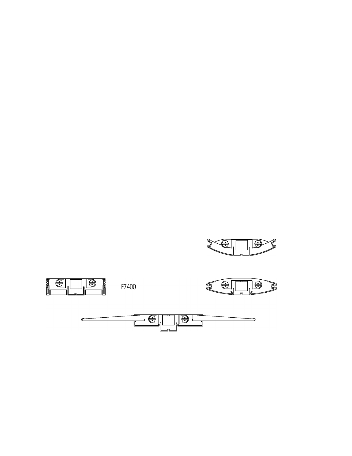
Instruction Sheet for Assembly and Installation of Pendant F7000
M fcj m
F7300 F7500
F7600
F7700
Lightolier is a Philips group brand
631 Airport Road, Fall River, MA 02720 • (508) 679-8131 • Fax (508) 674-4710
We reserve the right to change details of design, materials and finish.
www.lightolier.com © 2009 Philips Group • C0709
PHILIPS
Page 2
LIGHTOLIER*
Lighting Systems IS_F7000
Page 2 of 6
48.00" or 96.00"
------------------+---------------
Instruction Sheet for Assembly and Installation of Pendant F7000
48.00" or 96.00"--------------------
Figure 1
Lightolier is a Philips group brand
631 Airport Road, Fall River, MA 02720 • (508) 679-8131 • Fax (508) 674-4710
We reserve the right to change details of design, materials and finish.
www.lightolier.com © 2009 Philips Group • 00709
PHILIPS
Page 3

LIGHTOLIIÈR*
Lighting Systems IS_F7000
Page 3 of 6
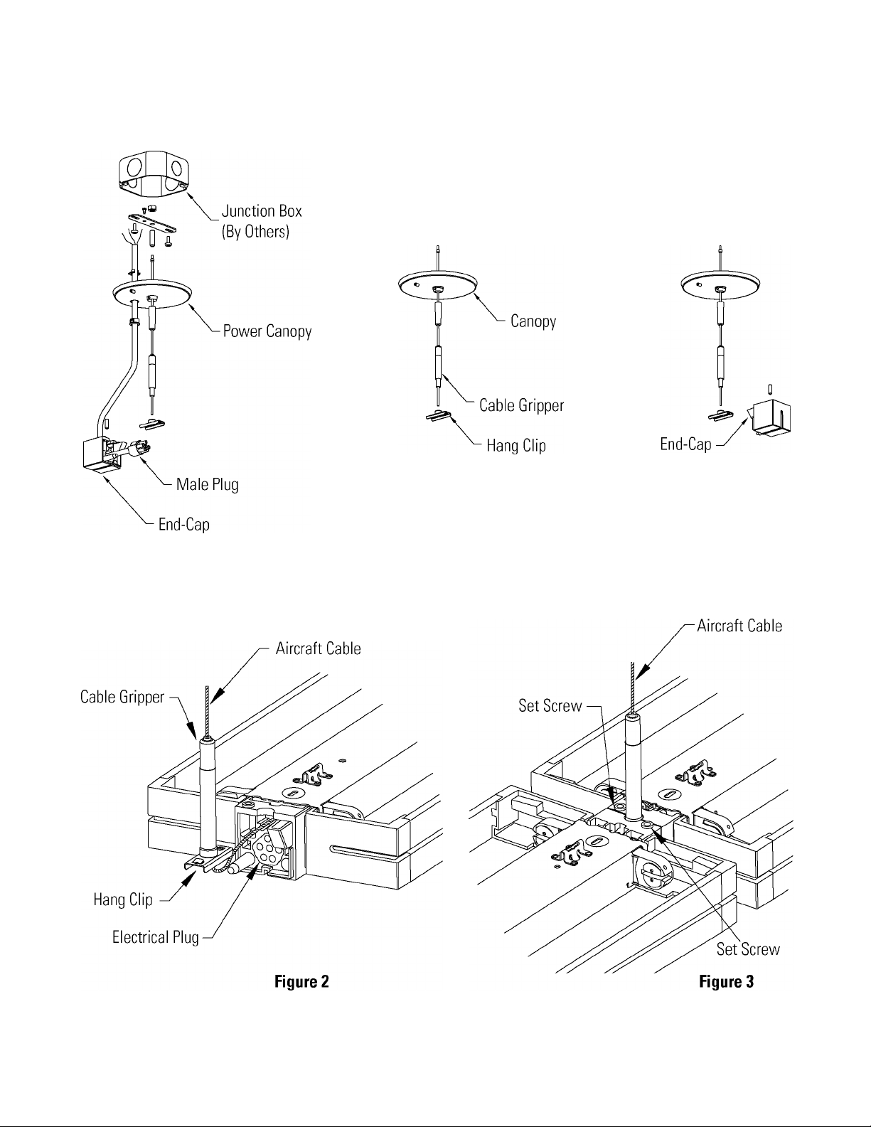
Step 1. Installing the Suspension
A. Install the suspension assemblies to the junction boxes. (Fig. 1)
B. Make sure to secure the green ground wire from SJT Cord.
C. The first suspension in each row should be from the power feed end set, which contains a male power cord and
an end cap. (Fig. 1)
D. Install the intermediate and end suspension assemblies to the ceiling structure support at 12", 24", 48" or 96"
as required by fixture length.
Step 2. Installing the First Fixture
A. Orient fixture so female plug in fixture faces the SJT cord male plug.
B. Insert the Hanging Clips from first and second suspension assemblies into the fixture. Make sure to push excess
cable into fixture. (Fig. 2)
C. Connect the SJT male cord plug into the first fixture female plug.
D. Push the end cap fiush with the fixture.
E. Tighten the set screws as joint. (Fig. 3) Be sure not to over-tighten.
F. Level fixture by pressing down on top of cable grippers and pushing or pulling on cables as required.
Instruction Sheet for Assembly and Installation of Pendant F7000
Step 3. Installing the Remaining Fixtures
A. Orient the next fixture's female plug so it faces the first fixture's male plug.
B. Insert the Hanging Clips from second and third suspension assemblies into the second fixture. Make sure to
push excess cable into fixture. (Fig. 2)
C. Push fixtures together. (Fig. 3)
D. Tighten down each of the set screws in both fixtures. (Fig. 3) Be sure not to over-tighten.
E. Level fixture by pressing down on top of cable grippers and pushing or pulling on cables as required.
F. Repeat step 3 as many times as required to complete row.
Step 4. End of Row
A. Push the end cap fiush with the last fixture in row.
B. Tighten the set screws on top. (Fig. 3) Be sure not to over-tighten.
Lightolier is a Philips group brand
631 Airport Road, Fall River, MA 02720 • (508) 679-8131 • Fax (508) 674-4710
We reserve the right to change details of design, materials and finish.
www.lightolier.com © 2009 Philips Group • 00709
PHILIPS
Page 4

LIGHTOLIIÈR*
Lighting Systems IS_F7000
Page 4 of 6
Instruction Sheet for Assembly and Installation of Pendant F7000
INTERMEDIATE POWER DROP ON 2-LIGHT FIXTURES
Step 1. Fixture Modification
Once you have determined which fixture will be taking the in-line power drop, you need to turn 1/4 turn fasteners
and lift power-tray away from fixture to expose Thru-power harness. Remove knockout on power-tray closest to
where power drop is to take place and install the bushing provided with cord kit. (Fig. 4)
Step 2. Power Splicing (where this is an additional drop)
Cut thru-power harness wires approximately 3" from end of fixture where the splice is taking place and cap wires
coming from pervious fixture. Route new power cord through the hole in the power tray where the knockout was re
moved and install the strain-relief at end of the cord. Splice cord to thru-power harness making sure to match wire
colors. Relocate power-tray and secure with 1/4 turn fasteners making sure not to pinch any wires. (Fig. 5)
Step 3. Power Splicing (where this is the only power drop)
Route the new power cord through the hole on the power tray where the knockout was removed and install the
strain-relief at end of cord. Tap cord to thru-power harness making sure to match wire colors. Relocate power-tray
and secure with 1/4 turn fasteners making sure not to pinch any wires. (Fig. 5)
Lightolier is a Philips group brand
631 Airport Road, Fall River, MA 02720 • (508) 679-8131 • Fax (508) 674-4710
We reserve the right to change details of design, materials and finish.
www.lightolier.com © 2009 Philips Group • C0709
PHILIPS
Page 5

LIGHTOLIIÈR*
Lighting Systems IS_F7000
Page 5 of 6
Instruction Sheet for Assembly and Installation of Pendant F7000
INTERMEDIATE POWER DROP ON 1-LIGHT FIXTURES
Step 1. Fixture Modification
Once you have determined which fixture will be taking the in-line power drop, you need to remove the refiector and
lift the power-tray away from fixture to expose the thru-power harness. Next relocate the socket on socket-bracket
closest to where the power drop will take place. Fold-over tab on refiector to make room for socket. (Fig. 6)
Step 2. Power Splicing (where this is an additional drop)
Cut thru-power harness wires approximately 3" from end of fixture where splice is taking place. Cap wires coming
from pervious fixture. Route new power cord through the hole on power tray where the socket was relocated and
install the strain-relief at end of cord. Splice cord to thru-power harness making sure to match wire colors. Relocate
power-tray into housing making sure not to pinch any wires. (Fig. 7)
Step 3. Power Splicing (where this is the only power drop)
Route the new power cord through the hole on power tray where the socket was relocated and install the strainrelief at end of the cord. Tap cord to thru-power harness making sure to match wire colors. Relocate power-tray into
housing making sure not to pinch any wires. (Fig. 7)
Aircraft Cable
Socket
Figure 6
New Power Drop
Relocated
Socket
Figure 7
631 Airport Road, Fall River, MA 02720 • (508) 679-8131 • Fax (508) 674-4710
We reserve the right to change details of design, materials and finish.
www.lightolier.com © 2009 Philips Group • 00709
Lightolier is a Philips group brand
PHILIPS
Page 6

LIGHTOLIER*
Page 6 of 6 Instruction Sheet for Assembly and Installation of Pendant F7000
Lighting Systems IS_F7000
F7700 FIXTURE LENS INSTALLATION
Step 1. Make sure the lenses are fully engaged with the housing. (Fig. 8)
Step 2. Install 2 lens clips per lens. 1 right hand and 1 left hand utilizing the short screws provided.
(Fig. 9)
Step 3. Install 2 longer screws per lens along the housing screw groove approximate 6" from end
of lens. (Fig. 9)
Lightolier is a Philips group brand
631 Airport Road, Fall River, MA 02720 • (508) 679-8131 • Fax (508) 674-4710
We reserve the right to change details of design, materials and finish.
www.lightolier.com © 2009 Philips Group • C0709
PHILIPS
 Loading...