

Philips HTS-3377-W Service Manual
DVD Home Theatre System
HTS3377W/12
Service Manual
TABLE OF CONTENTS
Location of PCB Boards ............................................ 1-2
Versions Variation ...................................................... 1- 2
Specifications ............................................................ 1-3
Measurement Setup .................................................. 1-4
Service Aids .............................................................. 1-5
ESD & Safety Instruction .......................................... 1 -6
Lead-free soldering Information ................................ 1-7
Setting procedure & Repair Instructions........................2
Disassembly Instructions & Service positions .............. 3
Block & Wiri ng Diagram ................................................4
DISP+LED+VOL Board (main unit)................................ 5
Main Board (main unit) ..................................................6
Power Board (main unit) ................................................ 7
MP3 IN Board (main unit) .............................................. 8
Scart Board (main unit).................................................. 9
Main+Led+Head Board (wireless).............................. 10
SMPS Board (wireless)................................................ 11
Mechanical Exploded View & Part List........................ 12
Revision List ................................................................ 13
©
Copyright 2009 Philips Consumer Electronics B.V. Eindhoven, The Netherlands
All rightsreserved. No part of this publication may be reproduced, stored in a retrieval system or
transmitted, in any form or by any means, electronic, mechanical, photocopying, or otherwise
without the prior permission of Philips.
Published by SL0910 Service Audio Printed in The Netherlands Subject to modification
Chapter
GB
3141 785 33700
Version1.0
1 - 2
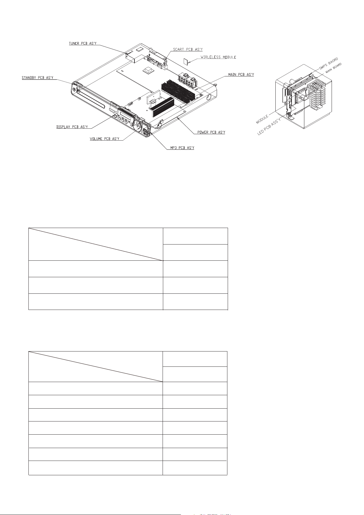
LOCATION OF PCB BOARDS
VERSION VARIATION:
Type/Versions
Features
HTS3377W
Output Power - 1000W
Voltage (220~240V)
MP3 Link
Main Board
DISP+LED+VOL Board
Scart Board
Type/Versions
Board in used
HTS3377W
Bd
Bd
Bd
/12
SERVICE SCNARIO MATRIX:
/12
x
x
x
*Bd = Board Level Repair
Power Board
Bd
MP3 IN Board
Bd
WIRELESS RECEIVER
Bd
Bd
Main+Led+Heat Board
SMPS Board
MAIN UNIT

1 - 3
SPECIFICATIONS
Playback media
DVD-Video, DVD+R/+RW, DVD-R/-RW, DVD+R DL, CD-R/
CD-RW, Audio CD, Video CD/SVCD, Picture CD, MP3-CD,
WMA-CD, DivX-CD, USB ash drive
Amplifier
Total output power . . . . . . . . . . . . . . . . . . . . . . . . . . . . . . . . . . . . . . . . . . . . . . . . . . . . . . . . . . . . . . . ......
Home Theatre mode . . . . . . . . . . . . . . . . . . . . . . . . . . . . . . . . . . . . . . . 1000 W(6 X 167)
Frequency response . . . . . . . . . . . . . . . . . . . . . . . . . . . . . . . . . . . . . . . . . . 40 Hz ~ 20 kHz
Signal-to-noise ratio . . . . . . . . . . . . . . . . . . . . . . . . . . . . . . . . . . . . . . . . . . . . . . . . . . . . . . > 60 dB
............................................................................... (A-weighted)
Input sensitivity . . . . . . . . . . . . . . . . . . . . . . . . . . . . . . . . . . . . . . . . . . . . . . . . . . . . . . . . . . . . . . . . . . . . ......
AUX . .. . .. . .. .. .. . .. . .. . .. . .. . .. .. .. . .. . .. . .. . .. .. .. . .. . .. . .. . .. .. .. . .. . .. . .. . .. . .. 400 mV
SCART TO TV . . . . . . . . . . . . . . . . . . . . . . . . . . . . . . . . . . . . . . . . . . . . . . . . . . . . . . . . . . . . . . . 250 mV
MP3 LINK . .. . .. .. .. . .. . .. .. .. . .. . .. .. .. . .. .. .. . .. . .. .. .. . .. . .. .. .. . .. . .. .. .. . .. 250 mV
Disc
Laser Type . . . . . . . . . . . . . . . . . . . . . . . . . . . . . . . . . . . . . . . . . . . . . . . . . . . . . . . . Semiconductor
Disc diameter . . . . . . . . . . . . . . . . . . . . . . . . . . . . . . . . . . . . . . . . . . . . . . . . . . . . . . . . . . . 12cm / 8cm
Video decording . . . . . . . . . . . . . . . . . . . . . . . . . . . . . . . . . . . . MPEG1/ MPEG2 / DivX
................................................................................. / DivX Ultra
Video DAC . . . . . . . . . . . . . . . . . . . . . . . . . . . . . . . . . . . . . . . . . . . . . . . . . . . . . . 12 bits, 108 MHz
Signal system . .. .. .. . .. .. .. . .. .. .. . .. .. .. . .. .. .. . .. .. .. . .. .. .. . .. .. .. . PAL / NTSC
Video S/N ........ ....... .......... ....... .......... .......... ....... .......... .... 56 dB
Audio DAC . . . . . . . . . . . . . . . . . . . . . . . . . . . . . . . . . . . . . . . . . . . . . . . . . . . . . . . . . 24 bits / 96 kHz
Frequency response . . . . . . . . . . . . . . . . . . . . . . . . . . . . . . . . . . . . . . . . . . . . . . . . . . . . . . . . . . . . ......
............................................................ 4 Hz - 20 kHz (44.1 kHz)
............................................................... 4 Hz - 22 kHz (48 kHz)
............................................................... 4 Hz - 44 kHz (96 kHz)
PCM . . . . . . . . . . . . . . . . . . . . . . . . . . . . . . . . . . . . . . . . . . . . . . . . . . . . . . . . . . . . . . . . . . . . . . . . . . IEC 60958
Dolby Digital .................... ... ... ................ IEC 60958, IEC 61937
DTS ........ ....... .......... ....... .......... ....... ...... IEC 60958, IEC 61937
Radio
Tuning range ........ ....... .......... ....... FM 87.5–108 MHz (50 kHz)
2 6 dB quieting sensitivity . . . . . . . . . . . . . . . . . . . . . . . . . . . . . . . . . . . . . . . . . . FM 22 dBf
IF rejection ratio . . . . . . . . . . . . . . . . . . . . . . . . . . . . . . . . . . . . . . . . . . . . . . . . . . . . . . . . . . FM 60 dB
Signal-to-noise ratio . . . . . . . . . . . . . . . . . . . . . . . . . . . . . . . . . . . . . . . . . . . . . . . . . . . . FM 50 dB
Harmonic distortion . . . . . . . . . . . . . . . . . . . . . . . . . . . . . . . . . . . . . . . . . . . . . . . . . . . . . . . . . FM 3%
Frequency response . . . . . . . . . . . . . . . . . . . . . . . . . . . . . . . . . . . . FM 180 Hz~10 kHz
........................................................................................./ ±6dB
Stereo separation . .. . .. .. .. . .. . .. .. .. . .. . .. .. .. . .. .. .. . .. . . FM 26 dB (1 kHz)
Stereo Threshold . . . . . . . . . . . . . . . . . . . . . . . . . . . . . . . . . . . . . . . . . . . . . . . . . . . . . . . . FM 29 dB
USB
Compatibility . . . . . . . . . . . . . . . . . . . . . . . . . . . . . . . . . . . . . . . . . . . . . . . Hi-Speed USB (2.0)
Class support . . . . . . . . . . . . . . . . . . . . . . . . . UMS (USB Mass Storage Class)
File system .................... ... ..................... FAT12, FAT16, FAT32
Main Unit
Power supply . . . . . . . . . . . . . . . . . . . . . . . . . . . . . . . . . . . . . . . . . . . . . . 220–240 V; ~ 50 Hz
Power consumption . . . . . . . . . . . . . . . . . . . . . . . . . . . . . . . . . . . . . . . . . . . . . . . . . . . . . . . . . 180 W
Standby power consumption . .. .. .. .. .. . .. .. .. .. .. . .. .. .. .. .. . .. .. .. .. . < 1 W
Dimensions (WxHxD) . .. .. .. .. .. .. .. .. .. .. .. .. .. .. .. 360 x 57 x 331 (mm)
Weight ........ ....... .......... ....... .......... ....... .......... .......... ....... 2.87 kg
Speakers
System . . . . . . . . . . . . . . ............................................. full range satellite
Speaker impedance . . . . . . . . . . . 4 ohm (centre), 4 ohm (Front/Rear)
Speaker drivers .........................................................................
Centre/Front/Rear . . . . . . . . . . . . . . .................................. 3” full range
Frequency response . . . . . . . . . . . . . . ..........................150 Hz ~ 20 kHz
Dimensions (WxHxD) . .. .. .. .. .. .. ...................................................
- Centre . . . . . . . . . . . . . . .................................. 244 x 103 x 74 (mm)
- Front . . . . . . . . . . . . . . .................................... 103 x 203 x 71 (mm)
- Rear . . . . . . . . . . . . . . ................................. 262 x 1199 x 264 (mm)
Weight ........ ...............................................................................
- Centre . . . . . . . . . . . . . . ........................................................0.79 kg
- Front . . . . . . . . . . . . . . ..........................................................0.54 kg
- Rear . . . . . . . . . . . . . . ...........................................................3.38 kg
Subwoofer
Impedance . . . . . . . . . . . . . . ......................................................... 4 ohm
Speaker drivers .............................................. 165 (6.5”) woofer
Frequency response . . . . . . . . . . . . . . ............................40 Hz ~ 150 Hz
Dimensions (WxHxD) . .. .. .. .. .. .. ................ 163 x 363 x 369 (mm)
Weight ........ ....................................................................4.85 kg
Wireless receiver
Power Consumption . .. .. .. .. .. . .. ............................................ 50 W
Frequency Response ................................................... 6000 Hz
S/N Ratio . .. . .. .. .. . .. . ......................................60 dB (A-Weighted)
Input Sensitivity: ........... .......................................... 400-600 mV
Distortion ........... ................................................................... 1%
Dimensions (WxHxD) . .. .. .. .. .. .. ...................................................
............................................................. 126 x 130.5 x 126 (mm)
Weight: ........ ...................................................................1.11 kg
Laser specification
Type . . . . . . . . . . . . . . ...................... Semiconductor laser GaAIAs (CD)
Wave length . . . . . . . . . . . . . . .. 645 - 665 nm (DVD),770 - 800 nm (CD)
Output power . . . . . . . . . . . . . . ................6 mW (DVD),7 mW (VCD/CD)
Beam divergence . . . . . . . . . . . . . . ..................................... 60 degrees.
Speci cations subject to change without prior notice.
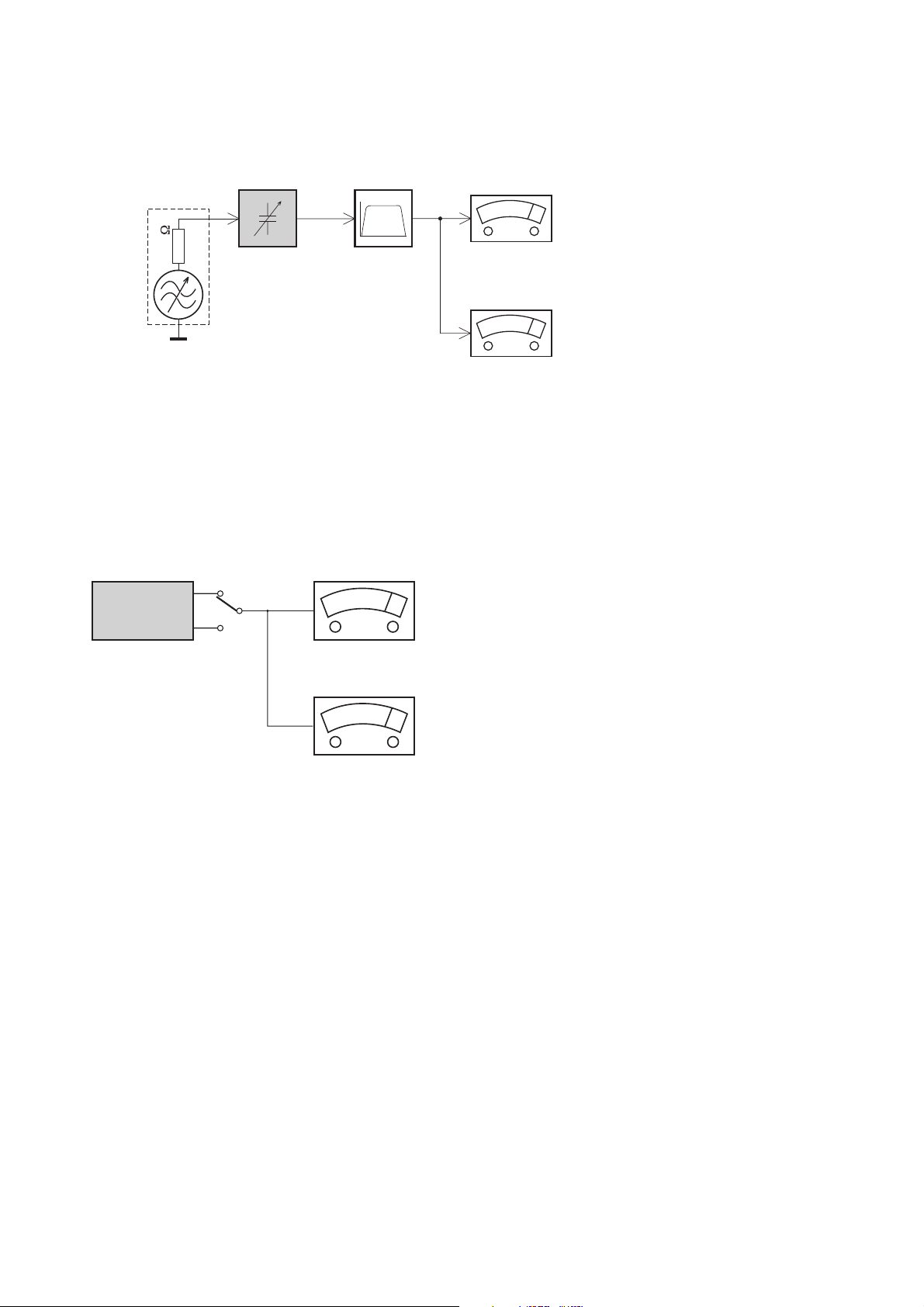
1 - 4
LEVEL METER
e.g. Sennheiser UPM550
with FF-filter
S/N and distortion meter
e.g. Sound Technology ST1700B
L
R
DUT
CD
Use Audio Signal Disc
(replaces test disc 3)
SBC429 4822 397 30184
Bandpass
250Hz-15kHz
e.g. 7122 707 48001
LF Voltmeter
e.g. PM2534
DUT
RF Generator
e.g. PM5326
S/N and distortion meter
e.g. Sound Technology ST1700B
Use a bandpass filter to eliminate hum (50Hz, 100Hz) and disturbance from the pilottone (19kHz, 38kHz).
Ri=50
Tuner FM
MEASUREMENT SETUP
1 - 5
Service Tools:
Universal Torx driver holder .................................4822 395 91019
Torx bit T10 150mm ...........................................4822 395 50456
Torx driver set T6-T20 .........................................4822 395 50145
Torx driver T10 extended .....................................4822 395 50423
Compact Disc:
SBC426/426A Test disc 5 + 5A ...........................4822 397 30096
SBC442 Audio Burn-in test disc 1kHz .................4822 397 30155
SBC429 Audio Signals disc .................................4822 397 30184
Dolby Pro-logic Test Disc ....................................4822 395 10216
SERVICE AIDS
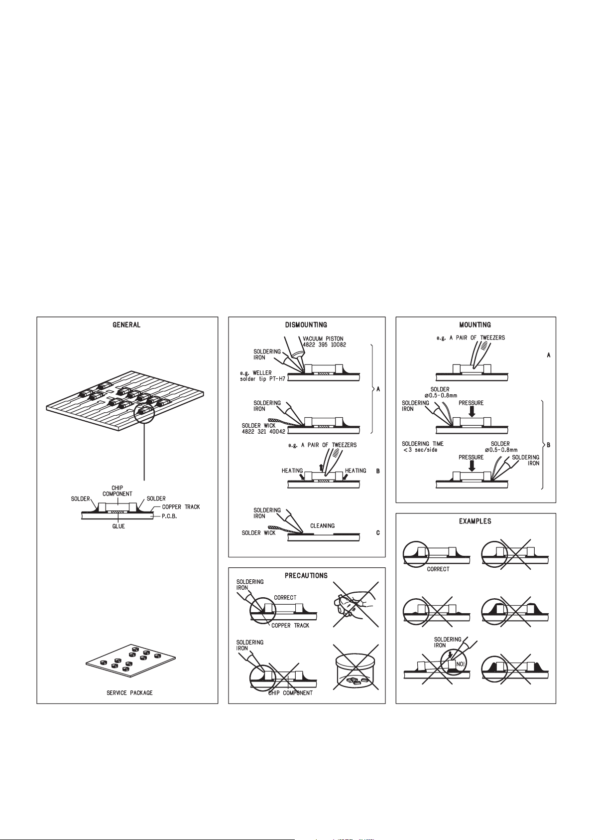
HANDLING CHIP COMPONENTS
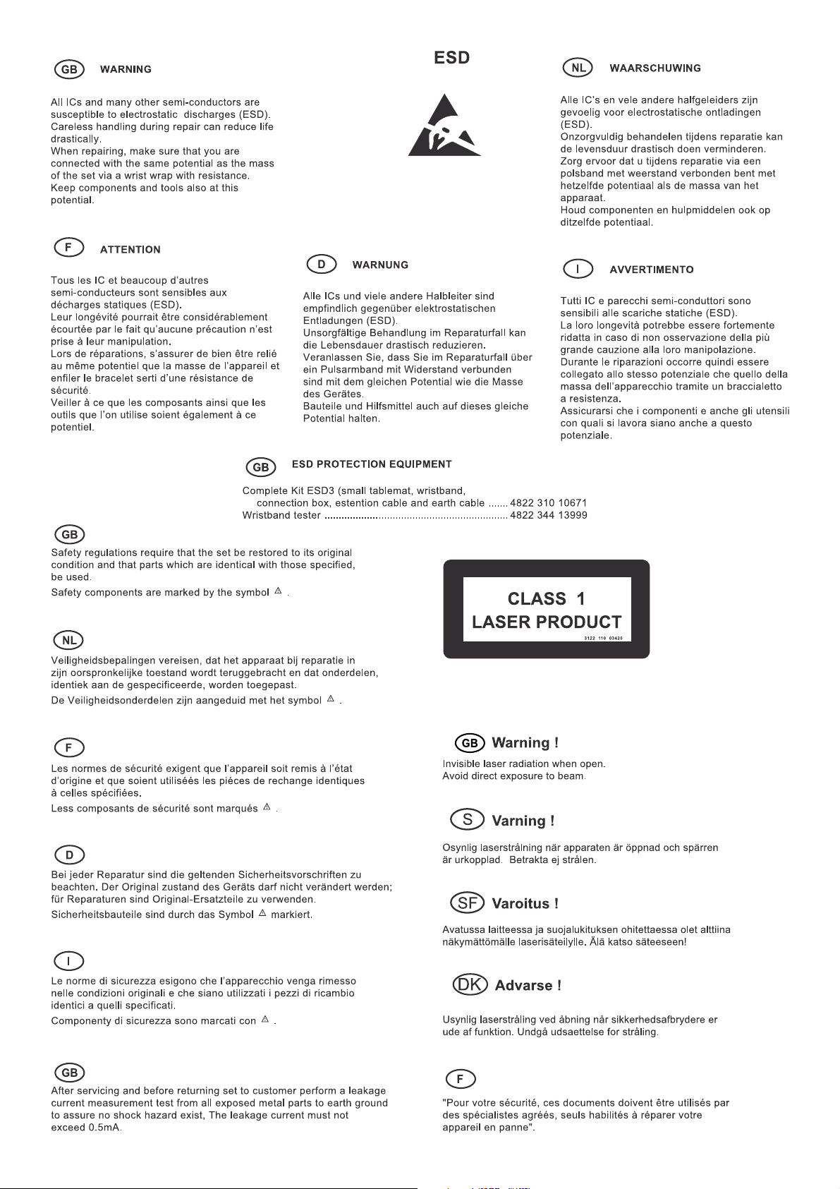
1 - 6
1 - 7
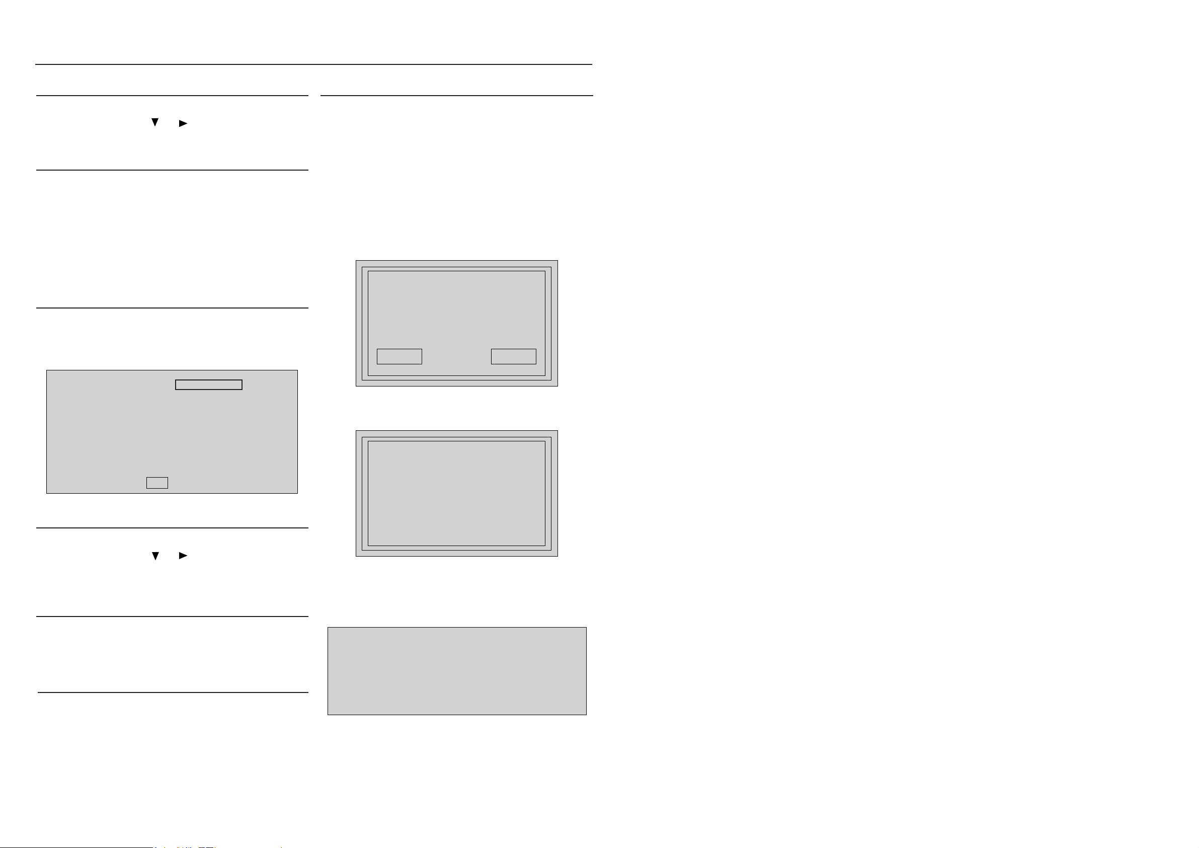
System , Region Code , etc. Setting Produre
2 - 12 - 1
1)System Reset
a) Press “SETUP“ button on R/C,TV will show setup menu
b) Select the menu using the and
c) Go preference page to do system reset
2)Region Code Change
a) In open mode, press”9” “9“ “9“ “9“ on R/C,then input desired
number to change region code :
1 USA
2 EU
3 AP
4 Australia ,NZ , Latam
5 Russia , INDIA
6 CHINA
3)Version Control Change
a) In open mode, press “1“ “5“ “9“ on R/C
b) Press “ok” button to con rm
c) TV will show message as below:
on R/C
7) Upgrading new software
a) Copy “software les” into a CD-R
b) Open the CD Door,then insert the CD-R program disc
c) Close the CD Door
d) VFD will show:
“Loading“
“Erase” -- erase the ash memory
“Writing” about 1 minute
“done “
* the system will switch off and on again automatically.
e) OSD will show:
upgrade le detected
Do you wish to continue with
the software upgrade?
OK Cancel
Current model HTS3377W/12
Version: XX.XX.XX Release:XXXX.XX.XX
region :2 Servo:XX.XX.XX.XX
8032:XX.XX.XX.XX RISC: XX.XX.XX.XX
MCU:XX.XX
If current model does not match you set use down arrow
key on the remote to change
OK
4)Password Change
a) Press “SETUP“ button on R/C,TV will show setup menu
b) Select the menu using the and on R/C
c) Go preference page select “password“ to change
* 000000 is default password supplied.
5)Check on the Software Version
a) Open the CD Door
b) Press “INFO“ button on R/C
c) TV will show the version on screen
6)Trade model
a) Press “Open/Close “ button on R/C
b) Press “2” “5” “9” on R/C,VFD will display “TRA ON “ or “TRA
OFF“
f) Select “OK”, OSD will show:
upgrade in progress...
V337X
please do not unplug or
switch off the device.
CAUTION!
This information is confi dential and may not be
distributed.Only a qualifi ed se rvice person should
reprogram the Region Code.
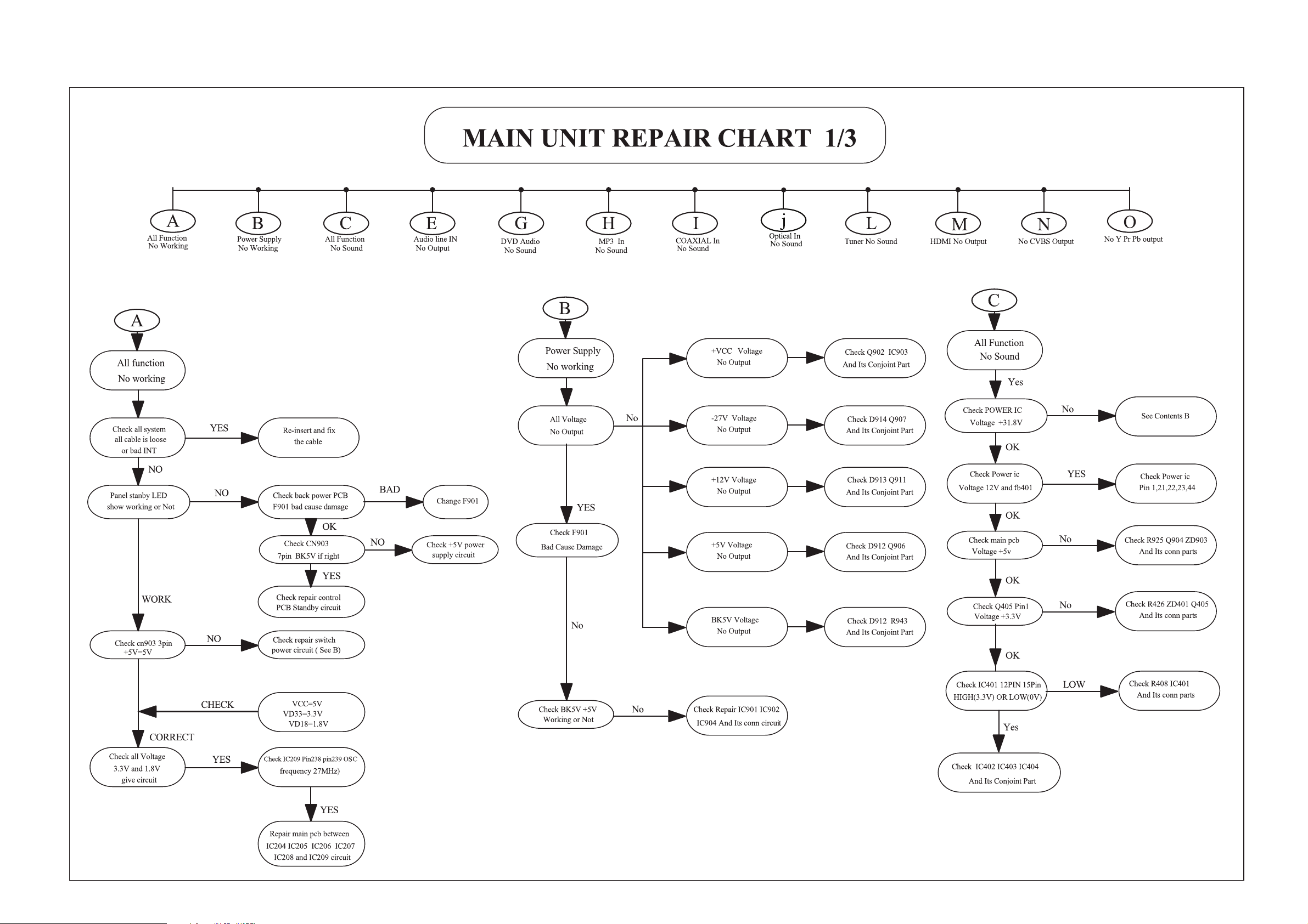
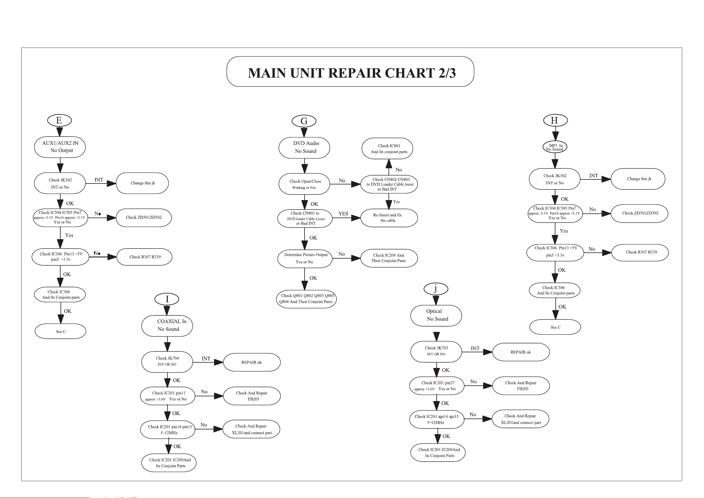
REPAIR INSTRUCTIONS (One)_main unit
2 - 22 - 2
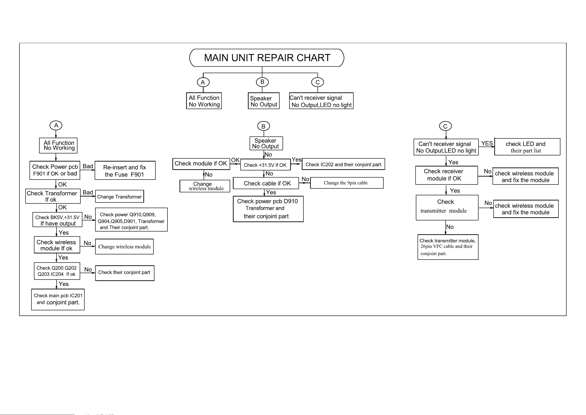
REPAIR INSTRUCTIONS (Two)_main unit
2 - 32 - 3
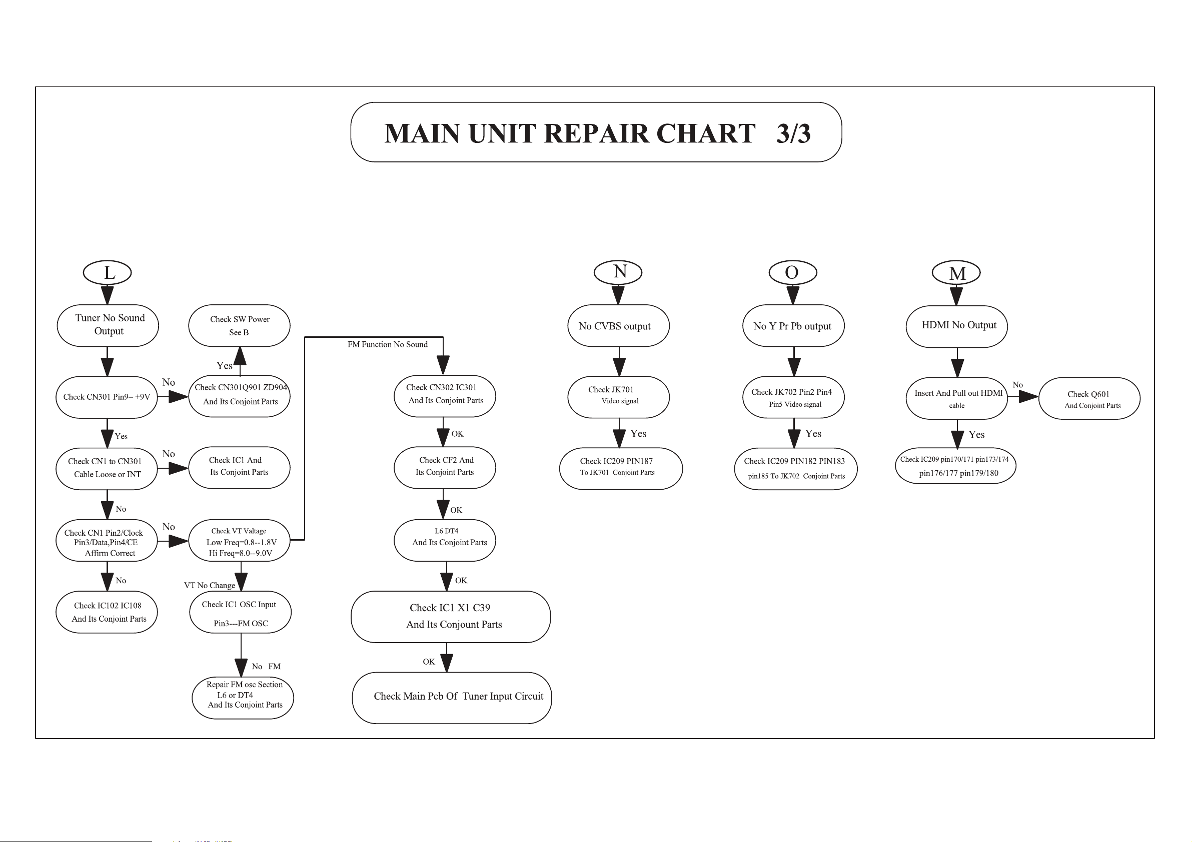
REPAIR INSTRUCTIONS (Three)_main unit
2 - 42 - 4
REPAIR INSTRUCTIONS_wireless
2 - 52 - 5
3 - 1 3 - 1
DISASSEMBLY INSTRUCTIONS(part one _main unit)
3) Loosen 6 screws and remove the Top Cover by lifting the rear portion upwards before sliding it out towards the rear.
- 1 screw “A” each on the left & right side as shown in gure 4.
- 4 screws “B” at the back panel as shown in g ure 5.
4) Loosen 6 screws “C“ at the front panel bracket as in g ure 6A & gure 6B to remove the front panel.
24mm
mm2
Figure 2
Dismantling of the Front Panel Assemble
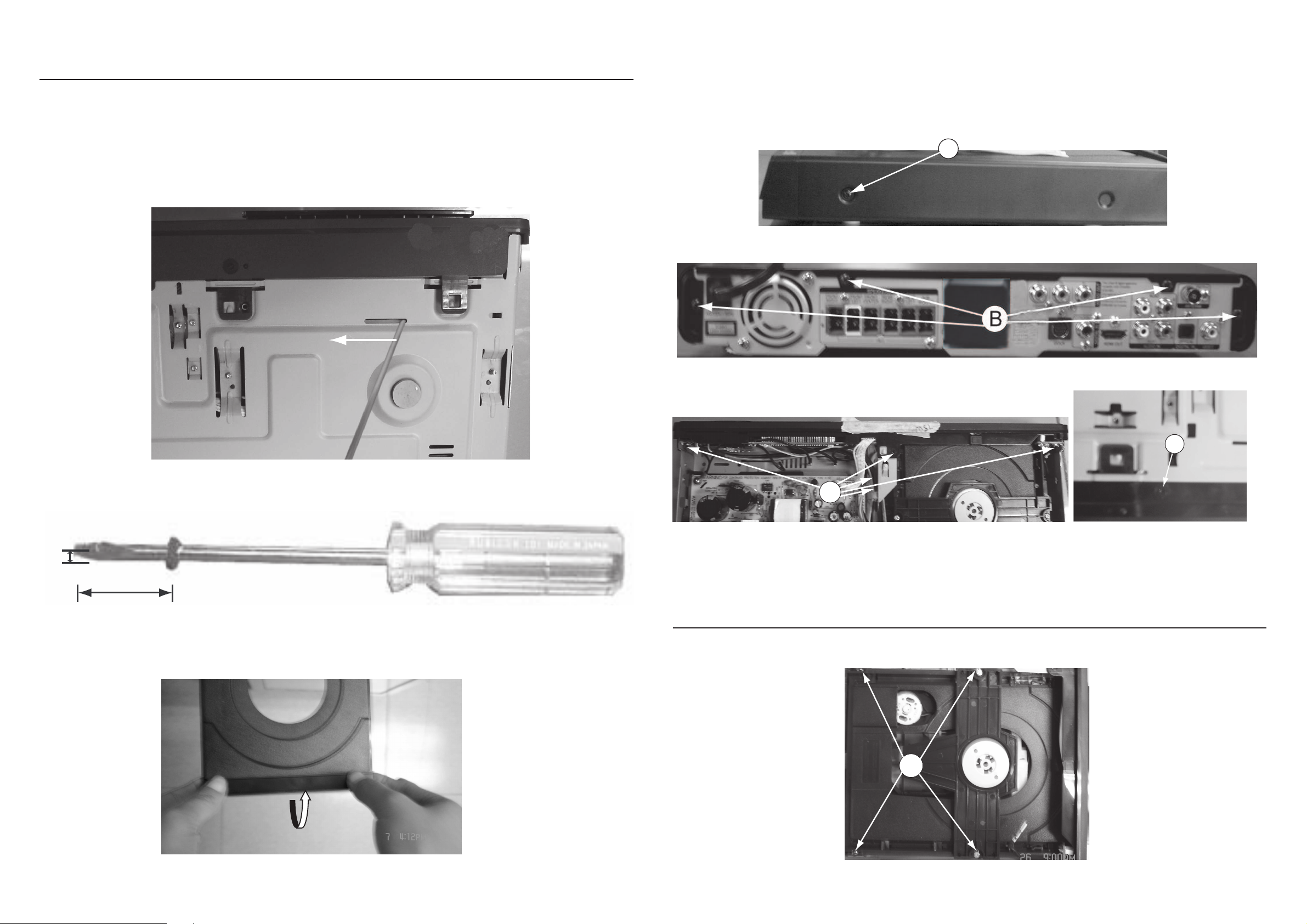
1) Open the DVD Tray by using the Open/Close Button while the Set is ON and disconnect the mains supply after removing the Tray
Cover.
Note: If this is not possible, the DVD Tray has to be open manually.
Take a mini screw driver about 2mm diameter and make a marking 24mm from the tip as shown in gure 2 . Place the set on its
side, insert the mini screw driver till the marking and slide it towards the left as shown in gure 1 until the Tray moves out of the Front
Panel.
2) Return the set to its upright position and remove the Tray Cover as shown in Figure 3 and close the tray manually by pushing it back
in.
Figure 1
Qvti
Figure 3
Figure 4
A
Figure 5
Figure 6A
C
Dismantling of the DVD Module
1) Loosen 4 screws “ D “ at the DVD Module as shown in gure 7.
Figure 7
D
C
Figure 6B
3 - 2 3 - 2
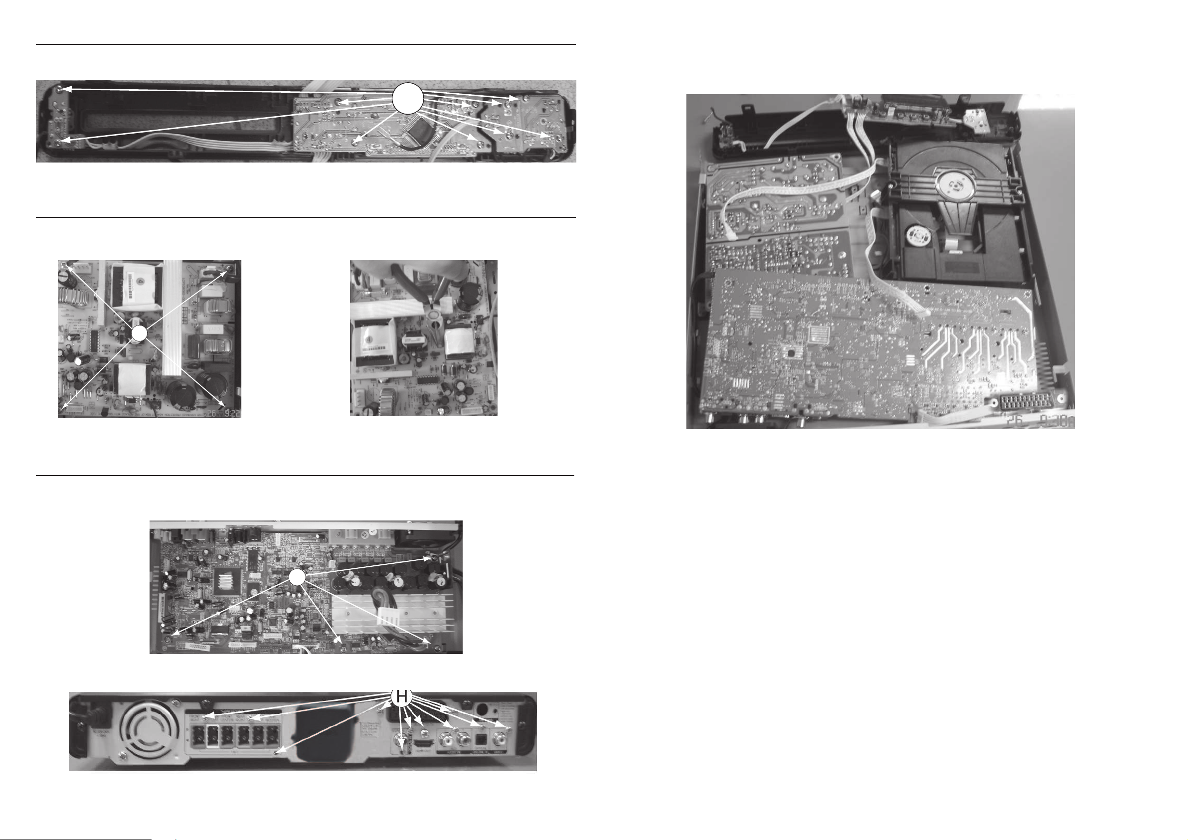
SERVICE POSITIONS
Service position A
Note:In some service positions the components or copper patterns of one board may risk touching its neighbouring pc boards or
metallic parts. To prevent such short-circuit use a piece of hard paper or other insulating material between them.
Dismantling of the MAIN+SCART Board
1) Loosen 4 screws “G” on the top of Main Board as shown in gure 11.
2) At the back panel, loosen 9 screws “H” to remove Main Board and loosen 2 screws to remove Scart Board as shown in gure 12.
Figure 9
Dismantling of the DISP+LED+VOL&MP3 IN Board
1) Loosen 10 screws “E” on the top of DISP+LED+VOL & MP3 IN Board as shown in gure 8.
Figure 8
E
Dismantling of the Power Board
1) Loosen 4 screws “F” on the top of Power Board as shown in gure 9.
2) With a pincers to nip this space as shown in gurer 10 and to take up the power board.
F
Figure 11
G
Figure 12
Figure 10
3 - 3 3 - 3
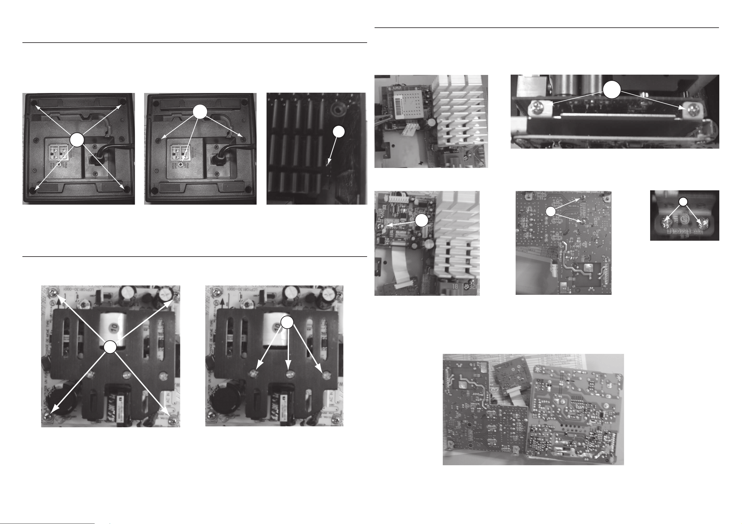
DISASSEMBLY INSTRUCTIONS (part two_wireless)
Dismantling of the Receiver module outer cover Assembly
1) Loosen 4 screws “A “on the bottom and remove the front & top Cover by lifting the panel upwards before sliding it from the set as shown
in gure 1.
2) Loosen 4 screws to remove the side & back & bottom panel:
-3 screws “B“ on the bottom as shown in gure 2;
-1 screw “C“ as shown in gure 3.
A
Figure 1
B
C
Figure 2 Figure 3
Dismantling of the SMPS Board
1) Loosen 4 screws “D” on the top of SMPS Board as shown in gure 4 to remove SMPS Board.
2) Loosen 3 screws “E“ as shown in gure 5.
D
E
Figure 4 Figure 5
Dismantling of the MAIN+LED+HEAT SINK Board
1) With a pincers to nip this space as shown in gure 6 and to take up this board.
2) Loosen 2 screws “F“ as shown in gure 7, and loosen 1 screw “G“ on the top of Wireless Main Board as shown in gure 8 to remove the
Wireless Main Board.
3) Loosen 2 screws “H“ at the bottom of Wireless Main Board to remove Heat Sink as shown in gure 9.
4) Loosen 2 screws “I“ on the top of LED Board as shown in gure 10.
F
Figure 6
Figure 7
G
H
Figure 8 Figure 9
SERVICE POSITIONS (wireless)
Note:In some service positions the components or copper patterns of one board may risk touching its neighbouring pc boards or
metallic parts. To prevent such short-circuit use a piece of hard paper or other insulating material between them.
I
Figure 10
 Loading...