

Philips HTS-3365-Mk2 Service Manual
1 - 1
HTS3365/55
©
Copyright 2008 Philips Consumer Electronics B.V. Eindhoven, The Netherlands
All rights reserved. No part of this publication may be reproduced, stored in a retrieval syst em or
transmitted, in any form or by any means, electronic, mechanical, photocopying, or otherwise
without the prior permission of Philips.
Published b
y LM0835 Service Audio Printed in The Netherlands Subject to modification
DVD Home Theater System
Version 1.0
TABLE OF CONTENTS
Service Manual
Service
Tfswjdf
Tfswjdf
3139 785 34590
GB
Chapter
Location of PCB Boards .............................................. 1-2
Versions Variation....................................................... 1-2
Specifications .............................................................. 1-3
Measurement setups................................................... 1-4
Service Aids................................................................. 1-5
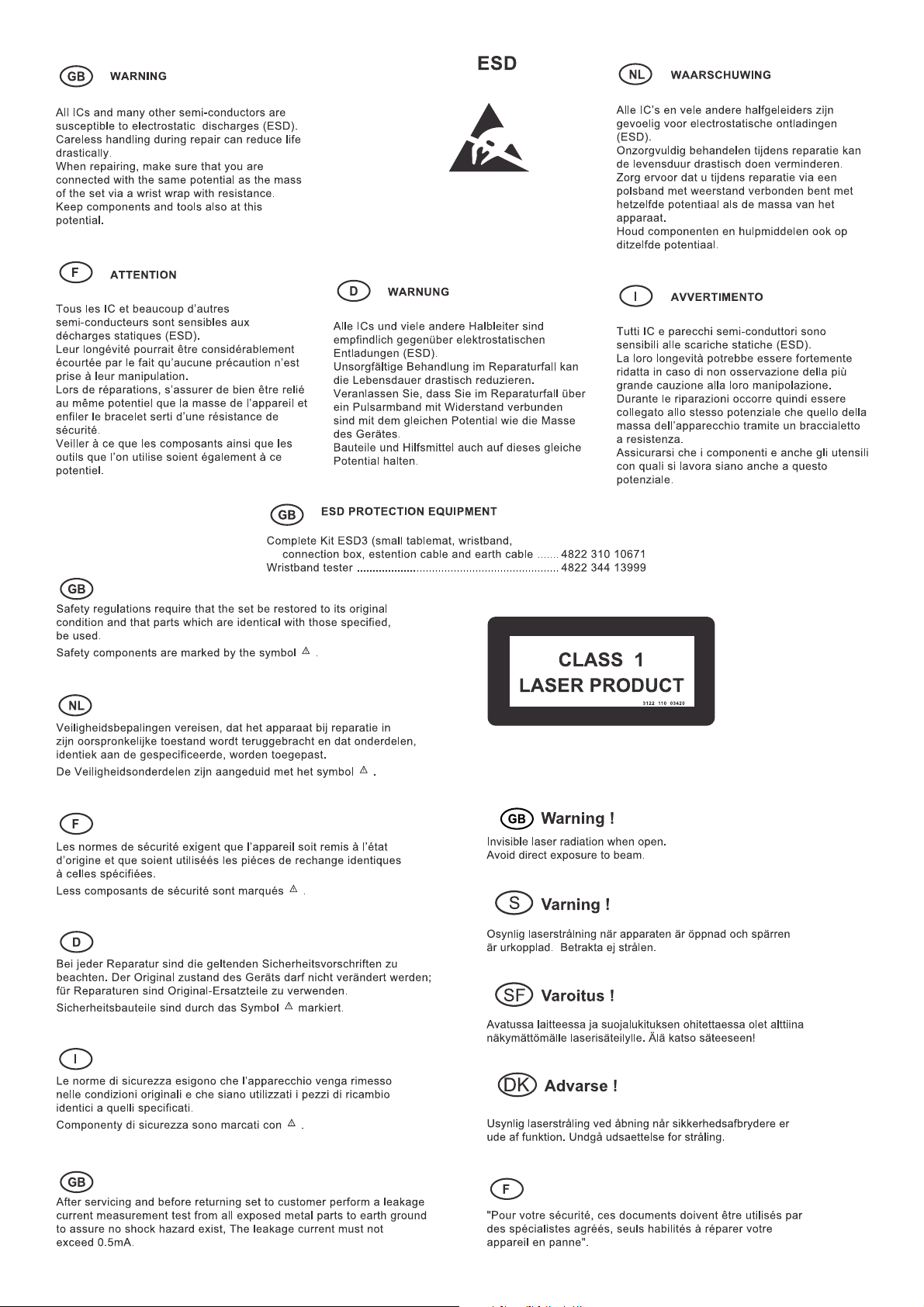
ESD & Safety instruction ............................................. 1-6
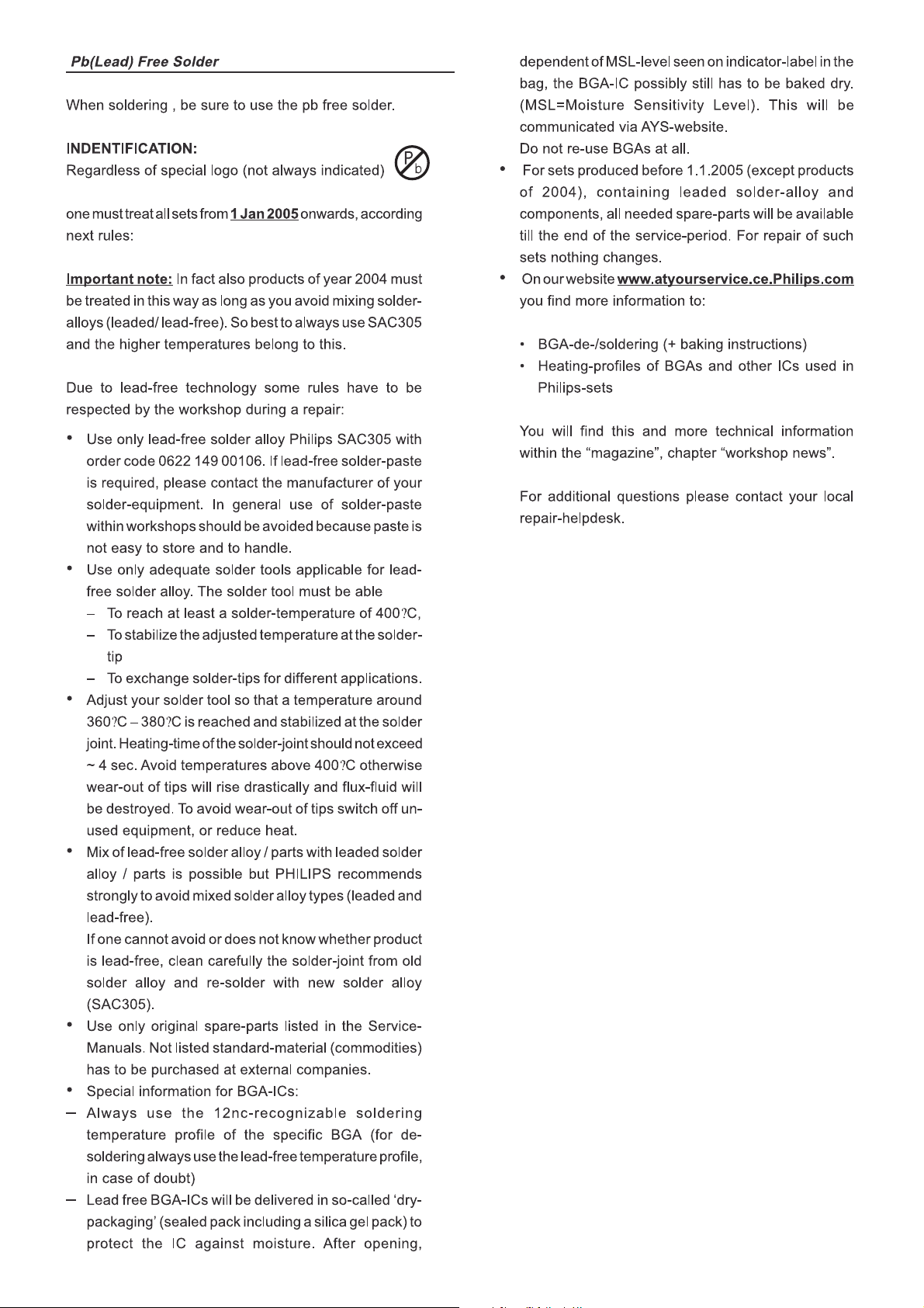
Lead-tree solding information...................................... 1-7
Setting procedure & Repair instructions......................... 2
Disassembly instruction & Service Postion....................3
Block & Wring Diagram .................................................. 4
VFD+JACK+VOL+STANDBY Board .............................. 5
Main Board ..................................................................... 6
Power Board................................................................... 7
AMP Board ..................................................................... 8
Mechanical Exploded View & Parts................................ 9
Revision List ................................................................. 10
Second Generation
This service manual is for HTS3365/55 Second Generation model,
which is different from the previous generation HTS3365/55 models.
For Second Generation model the serial number begin with
MF2AXXXXXXXXXX. Refer to the rating label illustration at right.
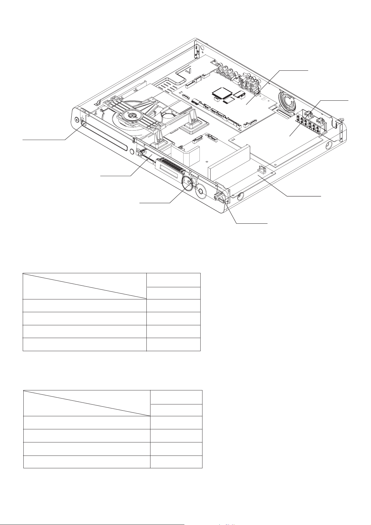
LOCATION OF PCB BOARDS
STANDBY PCB
VFD PCB
VOL PCB
JACK PCB
Power PCB
AMP PCB
MAIN PCB
1 - 2
VERSION VARIATION:
Main(Power Output-600W)
S-video out
Power Voltage (120V/230V)
WMA
SERVICE SCNARIO MATRIX:
Main Board
Power Board
Features
Boards in used
Type/Versions
Type/Versions
HTS3365
/55
X
X
X
X
HTS3365
/55
C
C
AMP Board
VFD+JACK+VOL+STANDBY Board
* C= Component
C
C

SPECIFICATIONS
1 - 3
AMPLIFIER
Total output power
Home Theatre mode . . . . . . . . . . . . . . . . . . . . . . . . . . . . . . . . . . . . . . 600 W
Frequency Response ....... 180 Hz – 18 kHz / ±3 dB
Signal-to-Noise Ratio: . . . . . . . . . . . . > 60 dB (A-weighted)
Input Sensitivity
AUX 1 . .. .. .. .. .. .. .. . .. .. .. .. .. .. .. .. .. .. . .. .. .. .. .. .. .. . .. .. . 400 mV
AUX 2 . .. .. .. .. .. .. .. . .. .. .. .. .. .. .. .. .. .. . .. .. .. .. .. .. .. . .. .. .. 400 mV
MP3 LINK . .. .. ... ... .. .. .. ... .. .. .. ... ... .. .. .. ... .. .. .. ... . 400 mV
RADIO
Tuning Range . . . . . . . . . . . . . . . . . . . . . . . . . . . . . FM 87.5-108 MHz
.............................................................(50/100 kHz)
............................................. AM/MW 530-1700 kHz
....................................................................(10 kHz)
...........................................................531-1602 kHz
......................................................................(9 kHz)
26 dB Quieting
Sensitivity ............................................... FM 22 dBf,
................................................... AM/MW 5000μV/m
IF Rejection Ratio . . . . . . . . . . . . FM 60 dB, AM/MW 24 dB
Signal-to-Noise Ratio . . . . . . . FM 50 dB, AM/MW 30 dB
AM/MW Suppression Ratio ...................... FM 30 db
Harmonic Distortion . . . . . . . . . . . . . . . . . . . . . . . . . . . . FM Mono 3%
.......................................................... FM Stereo 3%
.............................................................. AM/MW 5%
Frequency Response ... FM 180 Hz–10 kHz / ±6 dB
Stereo Separation . . . . . . . . . . . . . . . . . . . . . . . FM 26 dB (1 kHz)
Stereo Threshold . . . . . . . . . . . . . . . . . . . . . . . . . . . . . . . . . . . . . FM 29 dB
DISC
Laser Type . . . . . . . . . . . . . . . . . . . . . . . . . . . . . . . . . . . . . . Semiconductor
Disc Diametre . . . . . . . . . . . . . . . . . . . . . . . . . . . . . . . . . . . . . . . 12cm / 8cm
Video Decoding . .. .. ... ... .. .. .. ... .. MPEG-1 / MPEG-2 /
.................................................. / DivX 3/4/5/6, Ultra
Video DAC . . . . . . . . . . . . . . . . . . . . . . . . . . . . . . . . . . . . . . . . . . . . . . . . . . . 12 Bits
Signal System . . . . . . . . . . . . . . . . . . . . . . . . . . . . . . . . . . . . . . PAL / NTSC
Video Format . . . . . . . . . . . . . . . . . . . . . . . . . . . . . . . . . . . . . . . . . . . 4:3 / 16:9
Video S/N ...................................................... 56 dB
Composite Video
Output . . . . . . . . . . . . . . . . . . . . . . . . . . . . . . . . . . . . . . . . . . . . . . . 1.0 Vp-p, 75Ω
Frequency Response ........ 4 Hz–20 kHz (44.1 kHz)
.............................................. 4 Hz–22 kHz (48 kHz)
.............................................. 4 Hz–44 kHz (96 kHz)
PCM . . . . . . . . . . . . . . . . . . . . . . . . . . . . . . . . . . . . . . . . . . . . . . . . . . . . . . . IEC 60958
Dolby Digital ....................... IEC 60958, IEC 61937
DTS .................................... IEC 60958, IEC 61937
MAIN UNIT
Power Supply Rating . . . . . . . . 110-127 V / 220-240 V~;
...................................................................50-60 Hz
Power Consumption .. ... ... ... ... ........................100 W
Dimensions . . . . . . . . . . . . . . ............... 435 x 58 x 360 (mm)
.................................................................(w x h x d)
Weight ......................................................... 3.75 kg
FRONT AND REAR SPEAKERS
System . . . . . . . . . . . . . . .......................... Full range satellite
Impedance . . . . . . . . . . . . . . ............................................3 Ω
Speaker drivers ...................... 3” full range speaker
Frequency response . . . . . . . . . . . . . . ........150 Hz – 20 kHz
Dimensions . . . . . . . . . . . . . . ............... 103 x 203 x 71 (mm)
.................................................................(w x h x d)
Weight .................................................0.54 kg/each
CENTRE SPEAKER
System . . . . . . . . . . . . . . .......................... Full range satellite
Impedance . . . . . . . . . . . . . . ........................................... 6 Ω
Speaker drivers: ........... 2 x 2.5” full range speaker+
........................................................... 1 x 2” tweeter
Frequency response . . . . . . . . . . . . . . ........150 Hz – 20 kHz
Dimensions . . . . . . . . . . . . . . ............... 440 x 105 x 75 (mm)
.................................................................(w x h x d)
Weight ......................................................... 1.39 kg
SUBWOOFER
Impedance . . . . . . . . . . . . . . ............................................6 Ω
Speaker drivers ...................... 165mm (6.5”) woofer
Frequency response . . . . . . . . . . . . . . ......... 40 Hz – 150 Hz
Dimensions . . . . . . . . . . . . . . ............. 163 x 363 x 369 (mm)
.................................................................(w x h x d)
Weight ......................................................... 5.08 kg
Speci cations subject to change without prior notice.
USB
Compatibility . . . . . . . . . . . . . . . . . . . . . . . . . . . . Hi-Speed USB (2.0)
Class Support . . . . . . UMS (USB MassStorage Class)
MTP . . . . . . . . . . . . . . . . . . . . . . . . . . . . . . . . . (Media TransferProtocol)
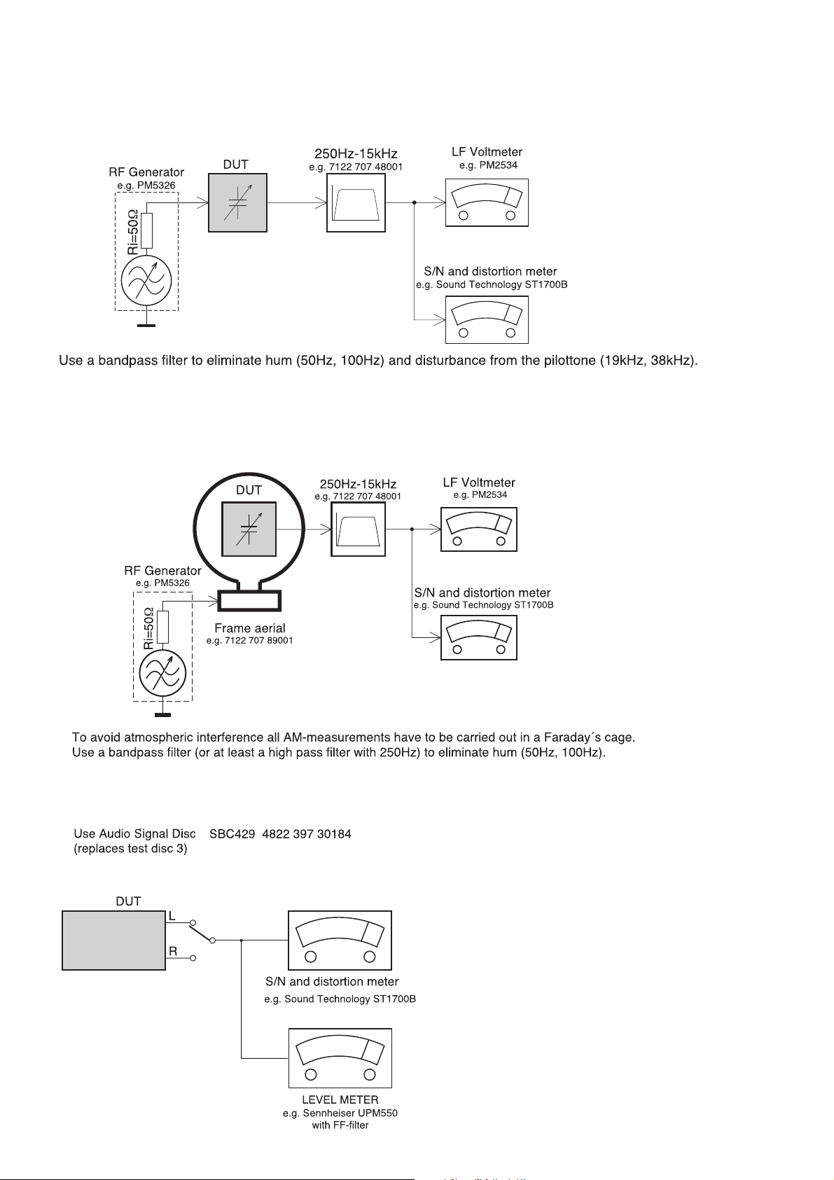
MEASUREMENT SETUP
CD
Tuner FM
Bandpass
Tuner AM (MW,LW)
Bandpass
1 - 4
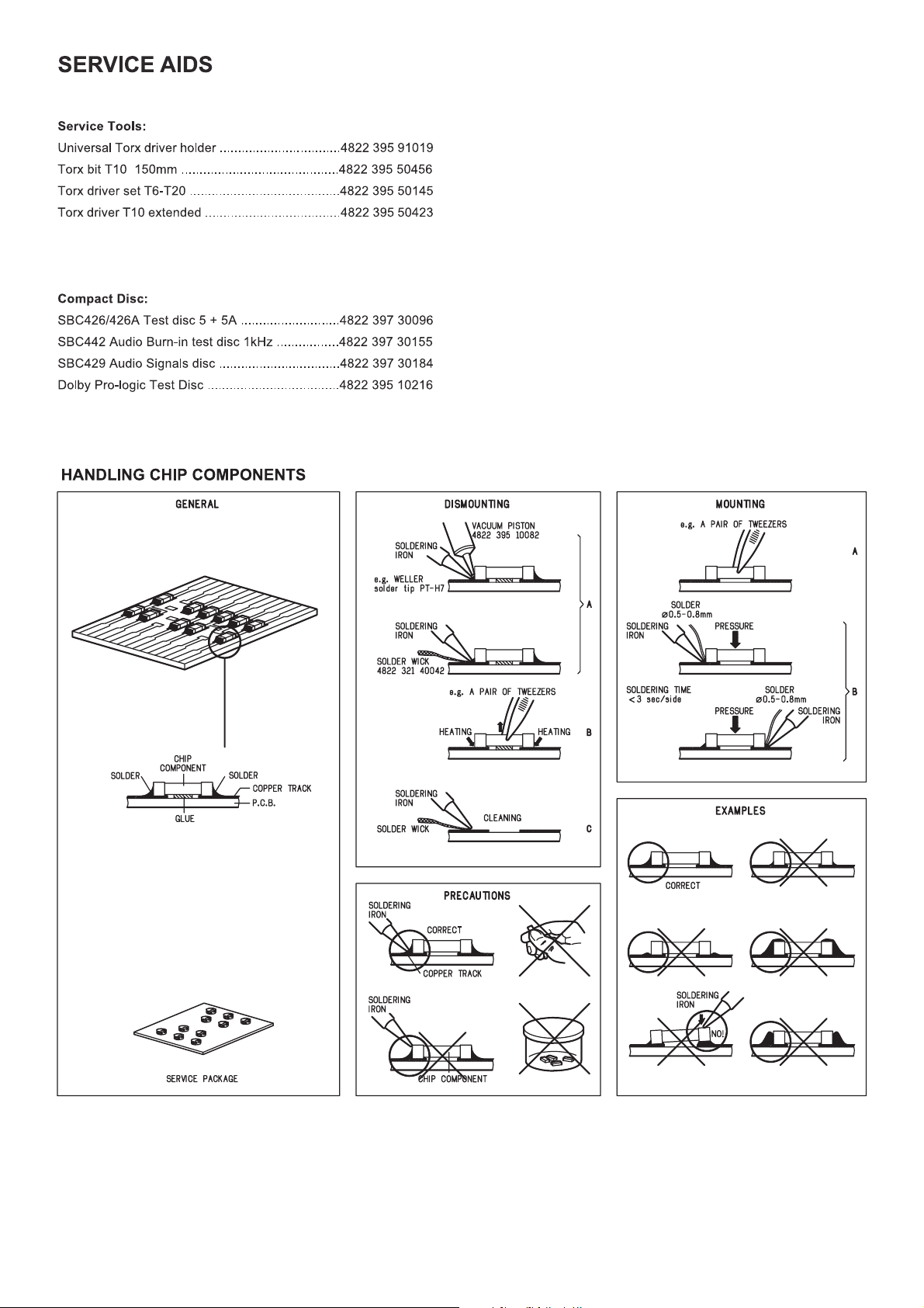
1 - 5
1 - 6
1 - 7

System , Region Code , etc. Setting Produre
2 - 12 - 1
1)System Reset
a) press “OPTIONS“ button on R/C,TV will show setup menu
b) select the menu using the and
c) go preference page to do sysytem reset
2)Region Code Change
a) In open model,press”9” “9“ “9“ “9“ on R/C,then input desired
number to change region code :
1 USA
2 EU
3 AP
4 Australia ,NZ , Latam
5 Russia , INDIA
6 CHINA
3)Version Control Change
a) In open model, press “1“ “5“ “9“ on R/C
b) press “ok” button to con rm
c) TV will show message as below:
on R/C
a) press “source” to select “FM” or “AM”
b) In “FM” or “AM” playback mode, press & hold “play/pause” button
until “Grid 9” or “Grid 10” appears
Note: repeating the same action will toggle back to it previous
tuning grid setting.
* “Grid 10” is default for/55 version.
8) Upgrading new sofeware
a) copy “sofeware les” into a CD-R disc
b) open the CD Door,then insert CD-R program disc
c) close the CD Door
d) VFD will show:
“Loading“
“Erase” -- erase the ash memory
“Writing” about 1 minute
“done “
* the system will switch off and on again automatically.
e) OSD will show:
Current model HTS3365/55
Version: 00.27.03_1 Release: 2008.05.22
region : 4 Servo: 5B.61.00.00
8032: 05.00.04.06 RISC:00.00.02.00
MCU: V10.08
IF current model does not match you set use down arrow
key on the remote to change
OK
4)Password Change
a) press “OPTIONS “ button on R/C,TV will show setup menu
b) select the menu using the and on R/C
c) go preference page select “password“ to change
* 000000 is default password supplied.
5)Check on the Sofeware Version
a) open the CD Door
b) press “INFO“ button on R/C
c) TV will show the version on screen
upgrade le detected
Do you wish to continue with
the sofeware upgrade?
OK Cancel
f) select “OK”, OSD will show:
upgrade in process...
V336X
please do not unplug or
switch off the device.
6)Trade model
a) press “Open/Close “ button on R/C
b) Press “2” “5” “9” on R/C,VFD will display “TRA ON “ or “TRA
OFF“
8) Produce to Change Tuner Grid
(only applicable for certain regions)
In some countries, the frequency step between adjacent channels
in the (AM/MW)/FM band is 9kHz/50kHz(10kHz/100kHz in some
areas).
CAUTION!
This information is confi dential and may not be
distributed.Only a qualifi ed s ervice person should
reprogram the Region Code.
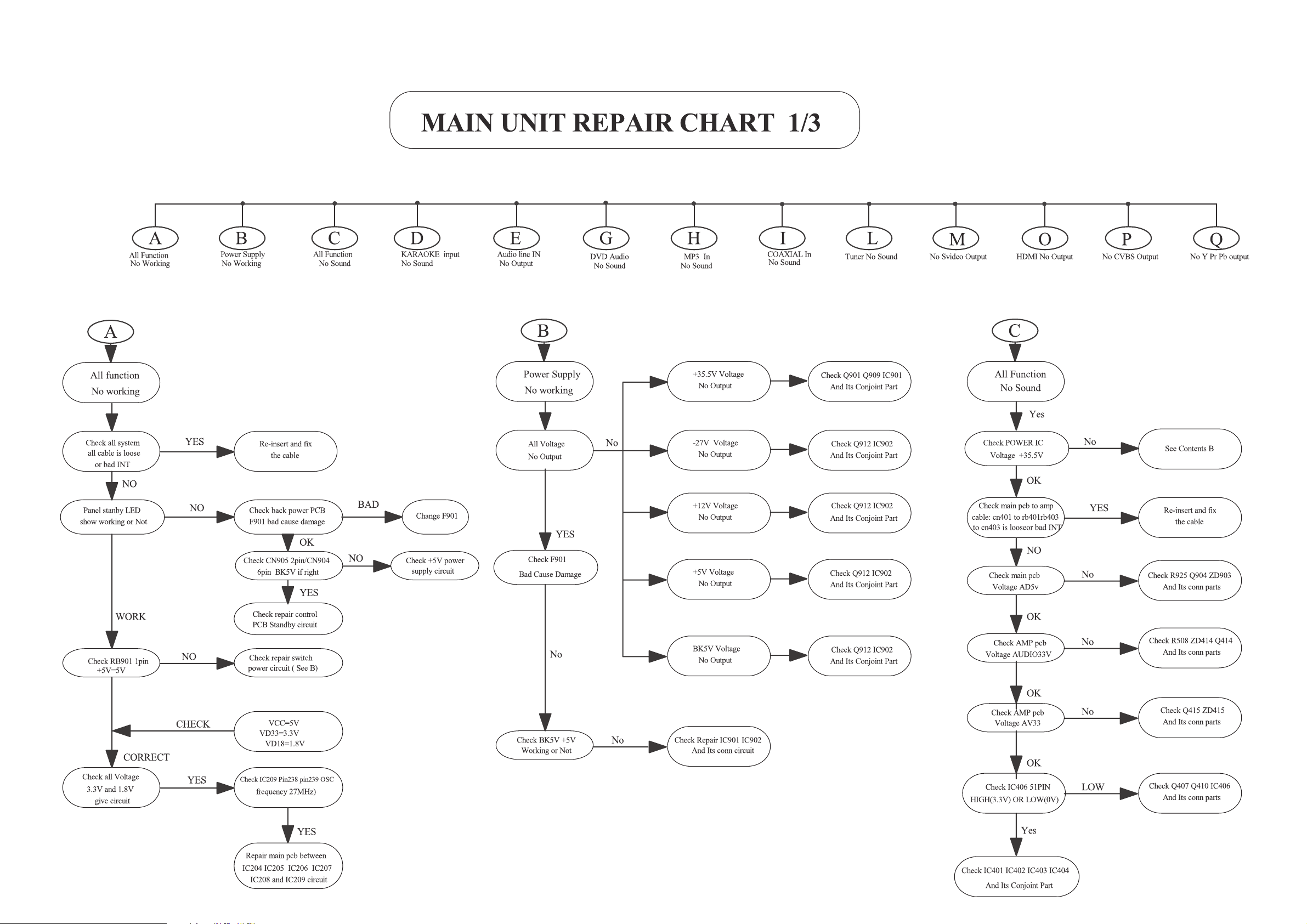
REPAIR INSTRUCTIONS (part one)
2 - 22 - 2
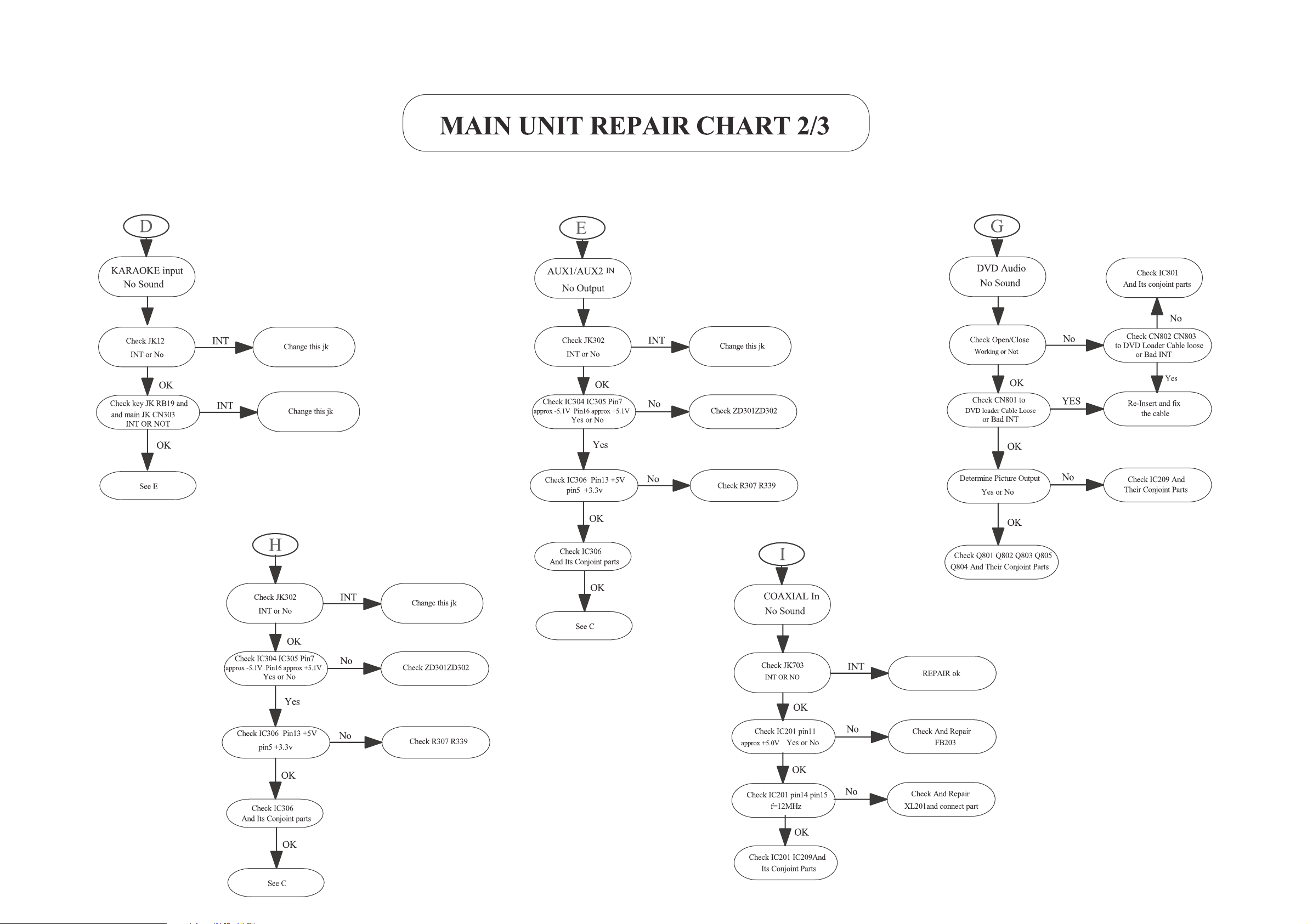
REPAIR INSTRUCTIONS (part two)
2 - 32 - 3
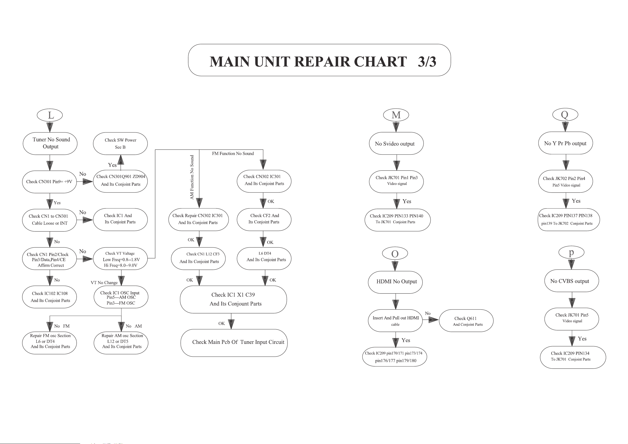
REPAIR INSTRUCTIONS (part three)
2 - 42 - 4
 Loading...