

Philips HTS3260/12 Schematic

1 - 1
Service
Service
BD Home Theater System
HTS3260/12
Tfswjdf
Tfswjdf
Service
Service Manual
TABLE OF CONTENTS
Location of PCB Boards ............................................ 1-2
Versions Variation...................................................... 1-2
Specifications ............................................................ 1-3
Measurement Setup .................................................. 1-4
Service Aids .............................................................. 1-5
ESD & Safety Instruction .......................................... 1-6
Lead-free soldering Information ................................ 1-7
Setting procedure & Repair Instructions........................ 2
Disassembly Instructions & Service positions .............. 3
Block & Wiring Diagram ................................................ 4
Quick Start Guide .......................................................... 5
VFD+VOL+USB+MP3 PCB .......................................... 6
MAIN PCB...................................................................... 7
POWER PCB ................................................................ 8
BD PCB.......................................................................... 9
TOUCH PCB ................................................................10
Mechanical Exploded view ..........................................11
Revision List ................................................................ 12
©
Copyright 2010 Philips Consumer Electronics B.V. Eindhoven, The Netherlands
All rights reserved. No part of this publication may be reproduced, stored in a retrieval system or
transmitted, in any form or by any means, electronic, mechanical, photocopying, or otherwise
without the prior permission of Philips.
Published by RY_HF1029 Service AudioPrinted in The Netherlands Subject to modification
Version 1.0
Chapter
3139 785 35500
GB
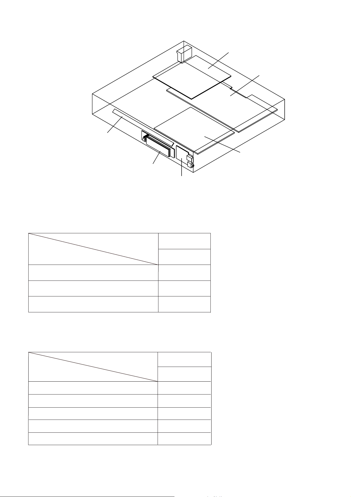
LOCATION OF PCB BOARDS
TOUCH PCB
VFD PCB
1 - 2
BD PCB
MAIN PCB
POWER PCB
Vol+USB+MP3 PCBB
VERSION VARIATION:
Type/Versions
Features
Output Power - 300W
Voltage (220~240V)
AUX/MP3
SERVICE SCNARIO MATRIX:
Type/Versions
Board in used
Main Board
HTS3260
/12
x
x
x
HTS3260
/12
C
Power Board
VFD+VOL+USB+MP3 Board
BD Board
Touch Board
*C = Component Level Repair
*Bd = Board Level Replacement
C
C
Bd
C

SPECIFICATIONS
1 - 3
Playback media
BD-Video, DVD-Video, DVD+R/+RW,DVD-R/-RW, DVD+R/R DL, CD-R/CDRW,Audio CD, Video CD/SVCD, PictureCD,
MP3-CD, WMA-CD, DivX (Ultra)-CD, USB ash drive.
File Format
Audio ........................................................................mp3, .wma
Video ...................................................... .avi, .divx, .mkv, .wmv
Picture ...................................................................jpg, .gif, .png
Amplifier
Total output power
Frequency response .................................. 20 Hz-20 kHz /±3dB
Signal-to-noise ratio... ................. > 65 dB (CCIR) /(A-weighted)
Input sensitivity:
AUX .............................................................................. 500 mV
MP3 LINK ...................................................................... 300 mV
Video
Signal system
HDMI output .............480i/576i, 480p/576p,720p, 1080i, 1080p
Audio
Sampling frequency:
MP3 .................................................. 32 kHz, 44.1 kHz, 48 kHz
WMA ............................................................... 44.1 kHz, 48 kHz
Constant bit rate:
MP3 ........................................................... 112 kbps - 320 kbps
WMA ............................................................ 48 kbps - 192 kbps
................................ 300 W RMS (30%THD)
........................................................ PAL / NTSC
Subwoofer
Impedance ....................................................................... 4 ohm
Speaker drivers .......................................165 mm (6.5”) woofer
Frequency response ............................................ 40 Hz-150 Hz
Dimensions (WxHxD) .............................. 123 x 369 x 309(mm)
Weight ............................................................................3.84 kg
Cable length ........................................................................ 4 m
Laser specification
Laser Type (Diode)
...................................................InGaAIP (DVD), A IGaAs (CD)
Wave length ..............................................405 +5nm/-5nm (BD)
............................................................ 650+13nm/-10nm (DVD)
...............................................................790 +15nm/-15nm(CD)
Output power (Max. ratings) ......... 20mW(BD), 7mW (DVD/CD)
Speci cations subject to change without prior notice.
......................................InGaN/AIGaN (BD)
Radio
Tuning range ..................................FM 87.5-108 MHz (50 kHz)
Signal-to-noise ratio ....................................................FM 55 dB
Frequency response .......................FM 180 Hz-12.5 kHz/ ±3dB
USB
Compatibility ...............................................Hi-Speed USB (2.0)
Class support ......................... UMS (USB Mass Storage Class)
File system ............................................. FAT16, FAT32, NTFS
Maximum memory support .......................................... < 160GB
Main Unit
Power supply ................................................ 220-240V; ~50 Hz
Power consumption ............................................................ 55W
Standby power consumption ........................................ ≤ 0.9 W
Dimensions (WxHxD) ................................ 360 x 58 x 351(mm)
Weight ............................................................................3.15 kg
Speakers
Speaker impedance ......................................................... 8 ohm
Speaker drivers .......................................1 x 3”woofer+1”twitter
Frequency response ...........................................150 Hz-20 kHz
Dimensions (WxHxD): ............................... 114x 311x114 (mm)
Weight: .......................................................................... 0.88 kg
Cable length: ....................................................................... 4 m

MEASUREMENT SETUP
Tuner FM
1 - 4
Bandpass
LF Voltmeter
e.g. PM2534
RF Generator
e.g. PM5326
DUT
250Hz-15kHz
e.g. 7122 707 48001
Ri=50
S/N and distortion meter
e.g. Sound Technology ST1700B
Use a bandpass filter to eliminate hum (50Hz, 100Hz) and disturbance from the pilottone (19kHz, 38kHz).
CD
Use Audio Signal Disc
(replaces test disc 3)
DUT
SBC429 4822 397 30184
L
R
S/N and distortion meter
e.g. Sound Technology ST1700B
LEVEL METER
e.g. Sennheiser UPM550
with FF-filter
SERVICE AIDS
Service Tools:
Universal Torx driver holder .................................4822 395 91019
Torx bit T10 150mm ...........................................4822 395 50456
Torx driver set T6-T20 .........................................4822 395 50145
Torx driver T10 extended .....................................4822 395 50423
Compact Disc:
SBC426/426A Test disc 5 + 5A ...........................4822 397 30096
SBC442 Audio Burn-in test disc 1kHz .................4822 397 30155
SBC429 Audio Signals disc .................................4822 397 30184
Dolby Pro-logic Test Disc ....................................4822 395 10216
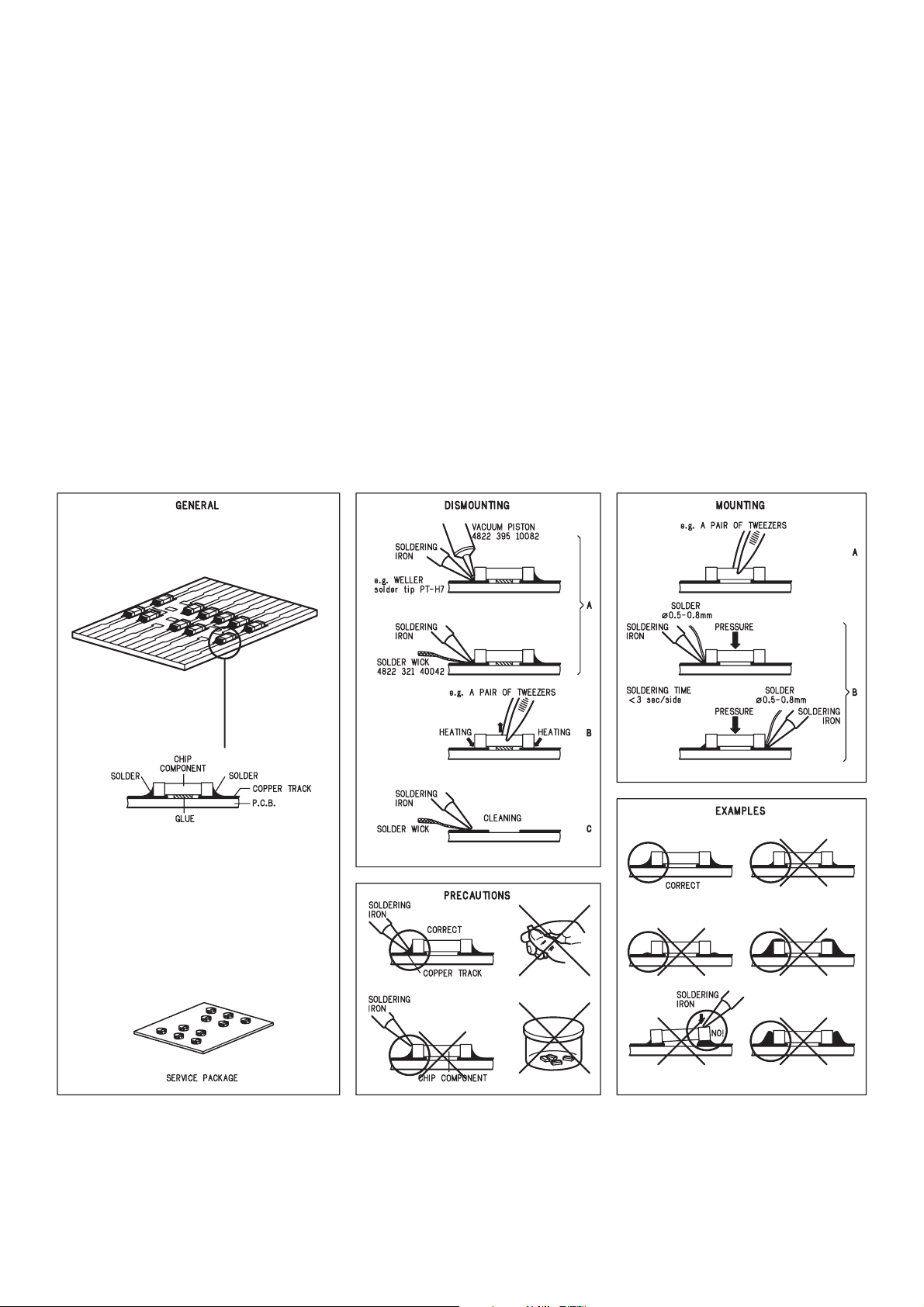
HANDLING CHIP COMPONENTS
1 - 5
GB
A
WARNING
1 - 6
ESD
WAARSCHUWING
NL
ll ICs and many other semi-conductors are
susceptible to electrostatic discharges (ESD).
Careless handling during repair can reduce life
drastically.
When repairing, make sure that you are
connected with the same potential as the mass
of the set via a wrist wrap with resistance.
Keep components and tools also at this
potential.
F
ATTENTION
Tous les IC et beaucoup d’autres
semi-conducteurs sont sensibles aux
décharges statiques (ESD).
Leur longévité pourrait être considérablement
écourtée par le fait qu’aucune précaution n’est
prise à leur manipulation.
Lors de réparations, s’assurer de bien être relié
au même potentiel que la masse de l’appareil et
enfiler le bracelet serti d’une résistance de
sécurité.
Veiller à ce que les composants ainsi que les
outils que l’on utilise soient également à ce
potentiel.
GB
Complete Kit ESD3 (small tablemat, wristband,
connection box, estention cable and earth cable .......4822 310 10671
Wristband tester .................................................................4822 344 13999
D
WARNUNG
Alle ICs und viele andere Halbleiter sind
empfindlich gegenüber elektrostatischen
Entladungen (ESD).
Unsorgfältige Behandlung im Reparaturfall kan
die Lebensdauer drastisch reduzieren.
Veranlassen Sie, dass Sie im Reparaturfall über
ein Pulsarmband mit Widerstand verbunden
sind mit dem gleichen Potential wie die Masse
des Gerätes.
Bauteile und Hilfsmittel auch auf dieses gleiche
Potential halten.
ESD PROTECTION EQUIPMENT
Alle IC’s en vele andere halfgeleiders zijn
gevoelig voor electrostatische ontladingen
(ESD).
Onzorgvuldig behandelen tijdens reparatie kan
de levensduur drastisch doen verminderen.
Zorg ervoor dat u tijdens reparatie via een
polsband met weerstand verbonden bent met
hetzelfde potentiaal als de massa van het
apparaat.
Houd componenten en hulpmiddelen ook op
ditzelfde potentiaal.
I
AVVERTIMENTO
Tutti IC e parecchi semi-conduttori sono
sensibili alle scariche statiche (ESD).
La loro longevità potrebbe essere fortemente
ridatta in caso di non osservazione della più
grande cauzione alla loro manipolazione.
Durante le riparazioni occorre quindi essere
collegato allo stesso potenziale che quello della
massa dell’apparecchio tramite un braccialetto
a resistenza.
Assicurarsi che i componenti e anche gli utensili
con quali si lavora siano anche a questo
potenziale.
GB
Safety regulations require that the set be restored to its original
condition and that parts which are identical with those specified,
be used.
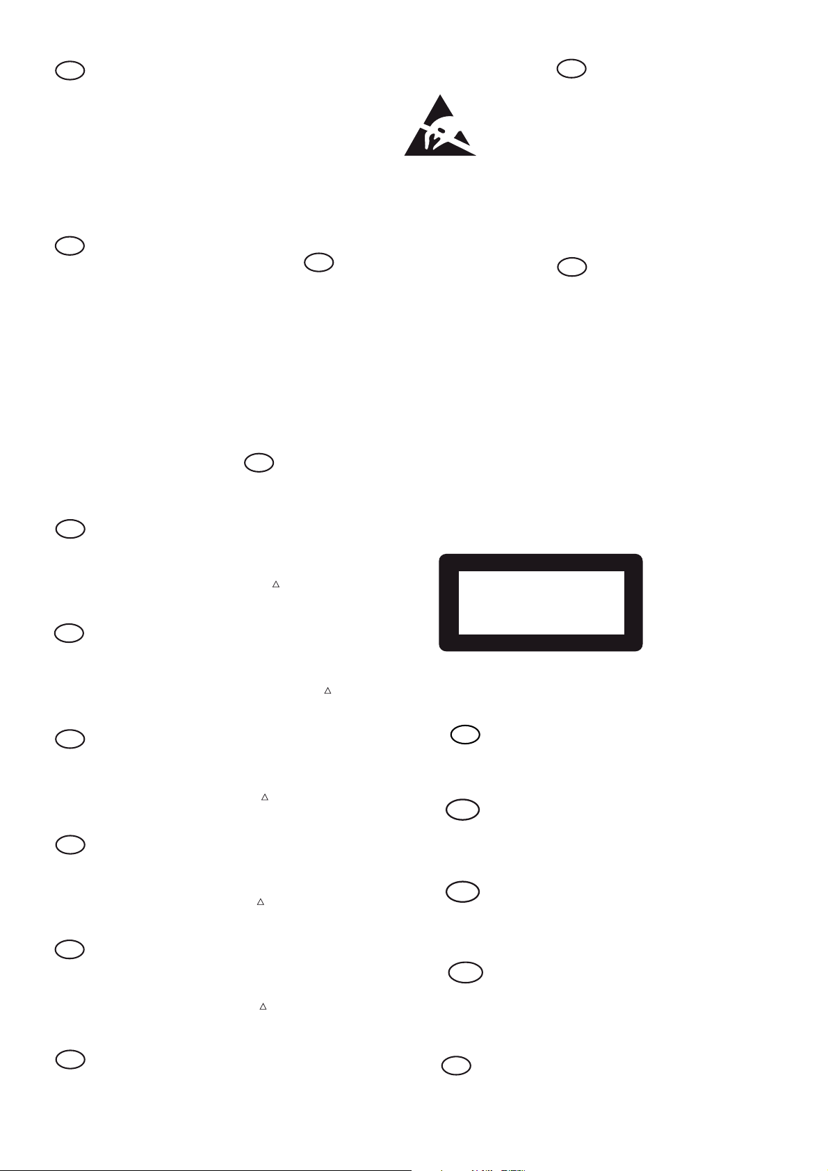
Safety components are marked by the symbol
!
.
CLASS 1
LASER PRODUCT
NL
Veiligheidsbepalingen vereisen, dat het apparaat bij reparatie in
zijn oorspronkelijke toestand wordt teruggebracht en dat onderdelen,
identiek aan de gespecificeerde, worden toegepast.
De Veiligheidsonderdelen zijn aangeduid met het symbol
!
.
3122 110 03420
F
Les normes de sécurité exigent que l’appareil soit remis à l’état
d’origine et que soient utiliséés les piéces de rechange identiques
à celles spécifiées.
Less composants de sécurité sont marqués
!
.
D
Bei jeder Reparatur sind die geltenden Sicherheitsvorschriften zu
beachten. Der Original zustand des Geräts darf nicht verändert werden;
für Reparaturen sind Original-Ersatzteile zu verwenden.
Sicherheitsbauteile sind durch das Symbol
!
markiert.
I
Le norme di sicurezza esigono che l’apparecchio venga rimesso
nelle condizioni originali e che siano utilizzati i pezzi di ricambio
identici a quelli specificati.
Componenty di sicurezza sono marcati con
!
.
GB
After servicing and before returning set to customer perform a leakage
current measurement test from all exposed metal parts to earth ground
to assure no shock hazard exist, The leakage current must not
exceed 0.5mA.
GB
Warning !
Invisible laser radiation when open.
Avoid direct exposure to beam.
S
Varning !
Osynlig laserstrålning när apparaten är öppnad och spärren
är urkopplad. Betrakta ej strålen.
Varoitus !
SF
Avatussa laitteessa ja suojalukituksen ohitettaessa olet alttiina
näkymättömälle laserisäteilylle. Älä katso säteeseen!
DK Advarse !
Usynlig laserstråling ved åbning når sikkerhedsafbrydere er
ude af funktion. Undgå udsaettelse for stråling.
F
"Pour votre sécurité, ces documents doivent être utilisés par
des spécialistes agréés, seuls habilités à réparer votre
appareil en panne".

Pb(Lead) Free Solder
When soldering , be sure to use the pb free solder.
INDENTIFICATION:
Regardless of special logo (not always indicated)
onemusttreatallsetsfrom1 Jan2005onwards,according
next rules:
Important note: In factalso products of year 2004must
be treatedin this way as long as you avoidmixingsolderalloys(leaded/ lead-free). Sobest to always use SAC305
and the higher temperatures belong to this.
Due to lead-free technology some rules have to be
respected by the workshop during a repair:
• Use only lead-free solder alloy Philips SAC305 with
ordercode 0622149 00106. Iflead-free solder-paste
is required, please contact the manufacturer of your
solder-equipment. In general use of solder-paste
withinworkshopsshouldbeavoided becausepaste is
not easy to store and to handle.
• Use only adequate solder tools applicable for lead-
free solder alloy. The solder tool must be able
– To reach at least a solder-temperature of 400@C,
– T o stabilize theadjustedtemperature atthesolder-
tip
– T o exchange solder-tips fordifferent applications.
• Adjust your solder tool so that a temperature around
360@C – 380@C is reachedand stabilized at thesolder
joint.Heating-timeofthesolder-jointshould notexceed
~ 4 sec. A void temperaturesabove 400@C otherwise
wear-out of tips will rise drastically and flux-fluid will
be destroyed. To avoid wear-out of tips switch off unused equipment, or reduce heat.
• Mix of lead-free solderalloy / parts with leadedsolder
alloy / parts is possible but PHILIPS recommends
strongly to avoidmixed solderalloy types (leaded and
lead-free).
Ifone cannot avoidordoes not know whetherproduct
is lead-free, clean carefully the solder-joint from old
solder alloy and re-solder with new solder alloy
(SAC305).
• Use only original spare-parts listed in the Service-
Manuals. Not listed standard-material(commodities)
has to be purchased at external companies.
• Special information for BGA-ICs:
– Always use the 12nc-recognizable soldering
temperature profile of the specific BGA (for desolderingalwaysuse thelead-free temperatureprofile,
in case of doubt)
– Lead free BGA-ICs willbe deliveredin so-called ‘dry-
packaging’(sealedpack including a silica gelpack) to
protect the IC against moisture. After opening,
1 - 7
dependent of MSL-level seenonindicator-labelin the
bag, the BGA-IC possibly still has to be baked dry.
(MSL=Moisture Sensitivity Level). This will be
communicated via AYS-website.
Do not re-use BGAs at all.
• Forsets producedbefore 1.1.2005 (except products
of 2004), containing leaded solder-alloy and
components,all neededspare-parts willbe available
till the end of the service-period. For repair of such
sets nothing changes.
• On our websitewww.atyourservice.ce.Philips.com
you find more information to:
• BGA-de-/soldering (+ baking instructions)
• Heating-profiles of BGAs and other ICs used in
Philips-sets
You will find this and more technical information
within the “magazine”, chapter “workshop news”.
For additional questions please contact your local
repair-helpdesk.
System , Region Code , etc. Setting Produre
1)Restore factory setting
a) Press “ ” <Home> button on R/C.
b) Select <SETUP>, then press “OK” button on R/C.
c) Select <Advanced setup> ,then press < OK > button on R/C.
d) Select <Restore default settings>,then press <OK> to confirm.
2)Password change
a) Press “
” <Home> button on R/C.
b) Select <SETUP>, then press “OK” button on R/C.
c) Select <preference setup>, then press <OK> button on R/C.
d) Select <Change Password> <Confirm>, then press <OK> button
on R/C.
“0000” is default password supplied.
3)Trade mode
5) Upgrading new software
Method 1: Update software from a USB storage device or CD-R
a) Create a folder named “UPG” in your CD-R or USB storage
device, and Copy the latest upgrading software into the folder.
b) Insert the CD-R program disc or connect the USB storage device
to the home theater.
c) Press “
d) Select <Advance Setup> <Software Update> <USB>.
e) TV will show message as follow:
Now searching for upgrade software!
Please wait...!
” <Home> button on R/C, and select <Setup>.
Software upgrade will take 5 minutes
Do not switch off!
Package version: 000029.0
Software BE Completed
Software FE Completed
Software MCU1: Not started
Software Dock: 2%
Software MCU3: Not started
Software upgrade will take 5 minutes
Do not switch off!
2 - 12 - 1
b) Press “
” <Home> button on R/C, and select <Setup>.
c) Select <Advance Setup> <Software Update> <Network>.
d) TV will show message as follow:
Now searching for upgrade software!
Please wait...!
Software updates for this player have been found. Do you want to
upgrade?
a) In open model,press “
” <Home> button on R/C.
b) Press “2” “5” “9” on R/C,VFD will display “TRA ON” or “TRA
OFF”.
4)Check software version
a) Press “
” <Home> button on R/C
b) Select <Setup>, then press <OK> button on R/C.
c) Select <Advanced Setup> <Version Info.>,then press <OK>
button on R/C.
d) TV will show message as follow:
Model:HTS3260/12
!
Version:
System SW:29.00
Subsystem SW:28-00-00-00
Ethernet MAC:00-25-D1-02-25-D4
http://www.philips.com/support
Close
e) Select <Close> on the version display screen and press <OK>
button to exit .
Software updates for this player have been found. Do you want to
upgrade?
Cancel
Start
f) Select <Start>, press <OK> button on R/C.
Software upgrade will take 5 minutes
Do not switch off!
Package version: 000029.0
Package version: 000029.0
Software BE Completed
Software FE Completed
Software MCU1: 1%
Software Dock: Failed
Software MCU3:
g)The set will shut down automatically when the software upgrade
is completed.
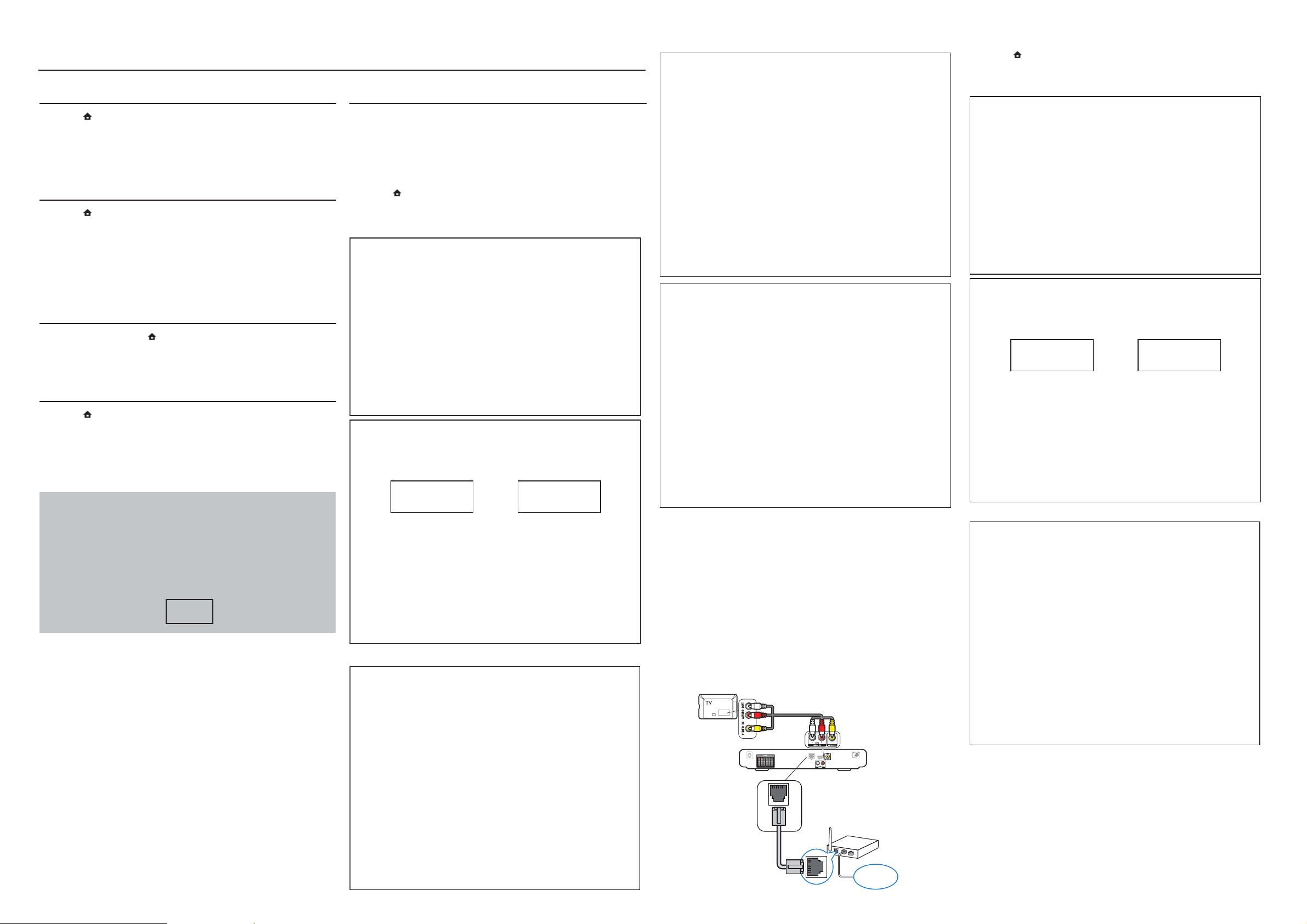
Method 2: Update software from the network
Note: To check for new updates, compare the current software
version of your home theater with the latest software version (if
available) on the Philips web site, and for BD-Live application and
software update, make sure that the network router has access to
the Internet and the firewall is disabled.
a) The “LAN” jack at the back panel of the set must be connect to
the network router via network cable and the set connect to TV,
Prepare the connection as shown follow:
Cancel
e) Select <Start>, press <OK> button on R/C.
Software upgrade will take 5 minutes
Do not switch off!
Package version: 000029.0
Software BE 80%
Software FE Completed
Software MCU1:
Software Dock:
Software MCU3:
Start
Software BE 80%
Software FE Completed
Software MCU1:
Software Dock:
Software MCU3:
LAN
www
Software upgrade will take 5 minutes
Do not switch off!
Package version: 000029.0
Software BE Completed
Software FE Completed
Software MCU1: Not started
Software Dock: 2%
Software MCU3: Not started
Software upgrade will take 5 minutes
Do not switch off!
c) Assembly Blu-ray Loader to “J802”,”J900”,”J906” on the top of
BD Board as shown below.
J900
J906
J802
d) Remove soldered joint on the ESD protection points.
The ESD protection points
on the bottom of board.
The ESD protection points
on the top of board.
e) Insert empty USB device of MSC type and press <OK> button
with R/C as shown follow:
“
f) Using
” buttons on R/C input the 6-digits OPU data
given on the 1D barcode (see label on the Loader) with the on-
screen selection and press <OK> button to save each digit entered
as shown follow:
2 - 22 - 2
j) If laser check fails press “ ” <Home> button and repeat OPU
matching procedure.
8)DVD Region Code Change
a) In open mode, press “8” “6” “8” “9” “3” “1” on R/C,then input
desired number to change region code:
1 USA
2 EU
3 APAC
4 Australia ,NZ, Latam
5 Russia ,India
6 China
CAUTION!
Package version: 000029.0
Software BE Completed
Software FE Completed
Software MCU1: 1%
Software Dock: Failed
Software MCU3:
f) The set will shut down automatically when the software upgrade
is completed.
6)How to replace the defective Blu-ray Loader
a) Remove the defective Blu-ray Loader.
b) Remove the shield cover at the top of Blu-ray Loader as shown
below.
Top side view of OPU
Bottom side view of OPU
Note: The 2 ESD protection points on any one side must be
soldered if
o the Blu-ray Loader is OK and needs to be disconnected
from connector J802, J900 and J906 of the BD Board.
o the defective Blu-ray Loader is needed to be send back to
supplier for failure analysis and to support backcharging evidence.
7)BD board and Blu-ray Loader OPU matching procedure
Note: This procedure must be performed whenever the defective
Blu-ray Loader or BD Board has been replaced .
a) Assembly Blu-ray Loader to BD Board.
b) Remove soldered joint on the ESD protection points.
c) Power on the set , press “
” <Home> button and input “5” “1”
“7” “7” on R/C.
d) Go into OSD Select mode and select item [5] ,then press <OK>
button on R/C as shown follow:
1 2 3 4 1 2
g) Press <Back> followed by <OK> button to finish OPU matching
and “
”<Home> button to exit.
h) Repeat step c) and select item [6] ,then press <OK> button on
R/C as shown follow:
This information is confi dential and may not be
distributed.Only a qualifi ed service person should
reprogram the Region Code.
i)Wait laser check to complete,press <stop> button to exit as
shown follow:
REPAIR INSTRUCTIONS
2 - 32 - 3
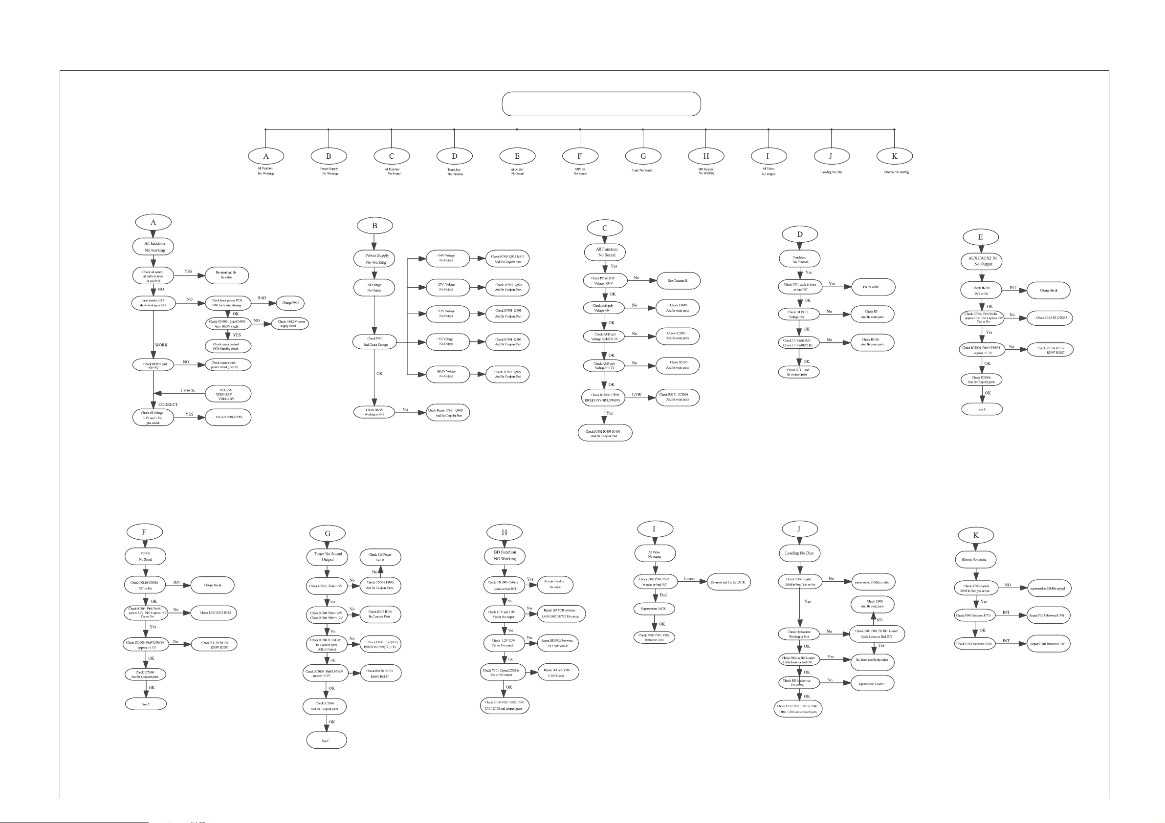
MAIN UNIT REPAIR CHART
DISASSEMBLY INSTRUCTIONS
3 - 1 3 - 1
Dismantling of theTop & Front Panel Assemble
1) Open the BD Tray by using the Open/Close Button while the Set is ON and disconnect the mains supply after removing the Tray
Cover.
Note: If this is not possible, the BD Tray has to be open manually.
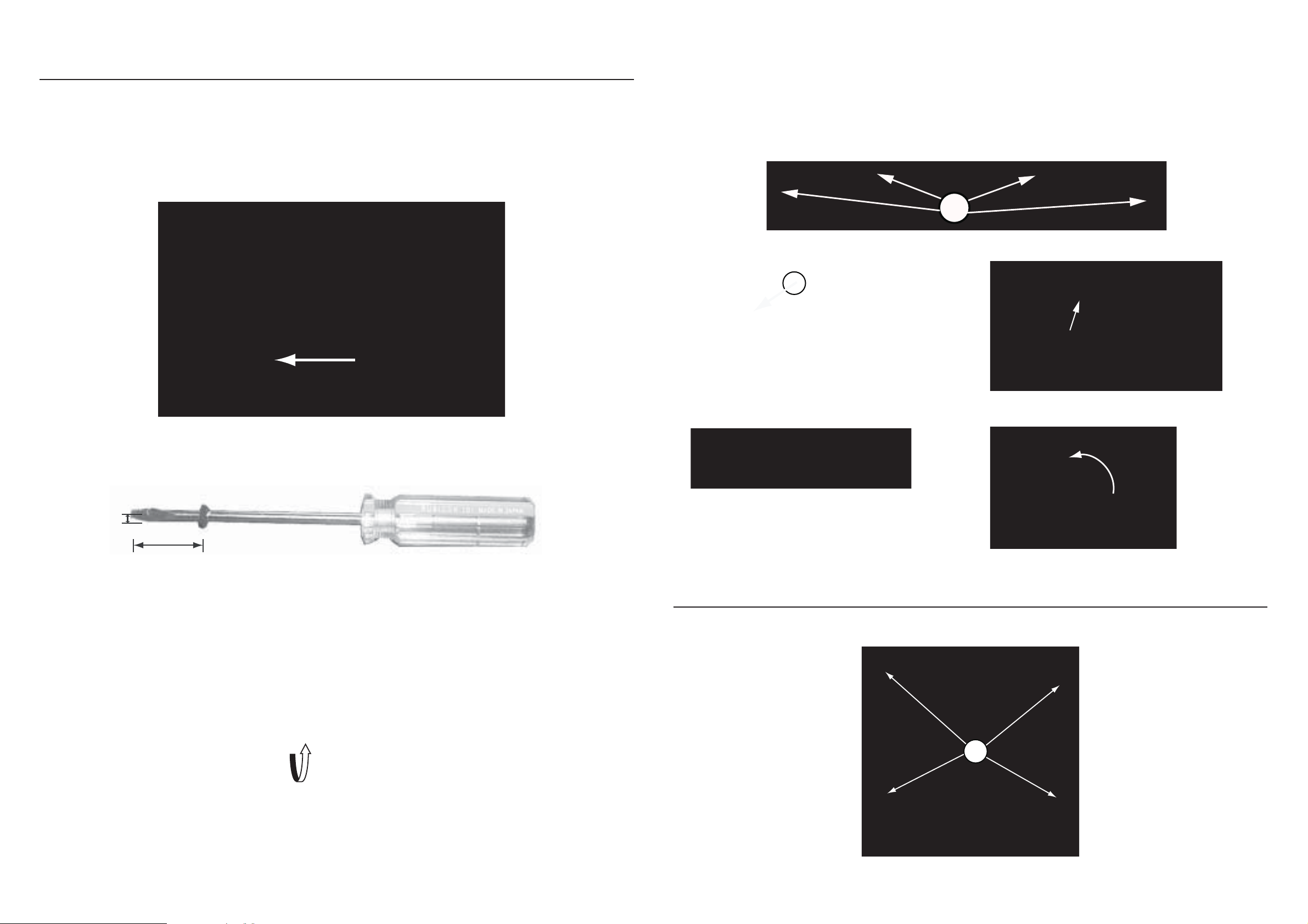
Take a mini screw driver about 2mm diameter and make a marking 24mm from the tip as shown in gure 2 . Place the set on its
side, insert the mini screw driver till the marking and slide it towards the left as shown in gure 1 until the Tray moves out of the Front
Panel.
2) Return the set to its upright position and remove the Tray Cover as shown in Figure 3 and close the tray manually by pushing it back
in.
Qvti
3) Loosen 6 screws and remove the Top Cover by lifting the rear portion upwards before sliding it out towards the rear.
- 4 screws “A” at the back panel as shown in gure 4.
- 1 screw “B” each on the left & right side as shown in gure 5.
4) Remove Volume KNOB as shown in gure 6 and using sleeve to lossen screw as shown in gure 7 & 8 to remove the front panel.
A
Figure 4
B
Push
Figure 5
mm2
24mm
Figure 6
Figure 1
Figure 7
Figure 8
Figure 2
Dismantling of the BD Module
1) Loosen 4 screws “ C “ at the BD Module as shown in gure 9.
Figure 3
C
Figure 9

3 - 2 3 - 2
Dismantling of the VFD+VOL+USB+MP3 Board
1) Loosen 6 screws “D” on the top of VFD+VOL+USB+MP3 Board as shown in gure 10.
D
Figure 10
Dismantling of the TOUCH Board
1) Loosen 4 screws “ E ” on the top of touch Board bracket as shown in gure 11.
Dismantling of the MAIN Board
1) Loosen 3 screws “ H ” on the top of MAIN Board as shown in gure 14.
2) Loosen 3 screws “ I ” at the back panel as shown in gure 15.
H
E
Figure 11
Dismantling of the BD Board
1) Loosen 4 screws “ F ” on the top of BD Board as shown in gure 12
2) At the back panel, loosen 2 screws “G” as shown in gure 13
F
Figure 14
I
Figure 15
Dismantling of the POWER Board
1) Loosen 5 screws “J ” on the top of Power Board as shown in gure 16.
k
Figure 12
G
Figure 13
J
Figure 16

SERVICE POSITIONS
3 - 3 3 - 3
Note:In some service positions the components or copper patterns of one board may risk touching its neighbouring pc boards or
metallic parts. To prevent such short-circuit use a piece of hard paper or other insulating material between them.
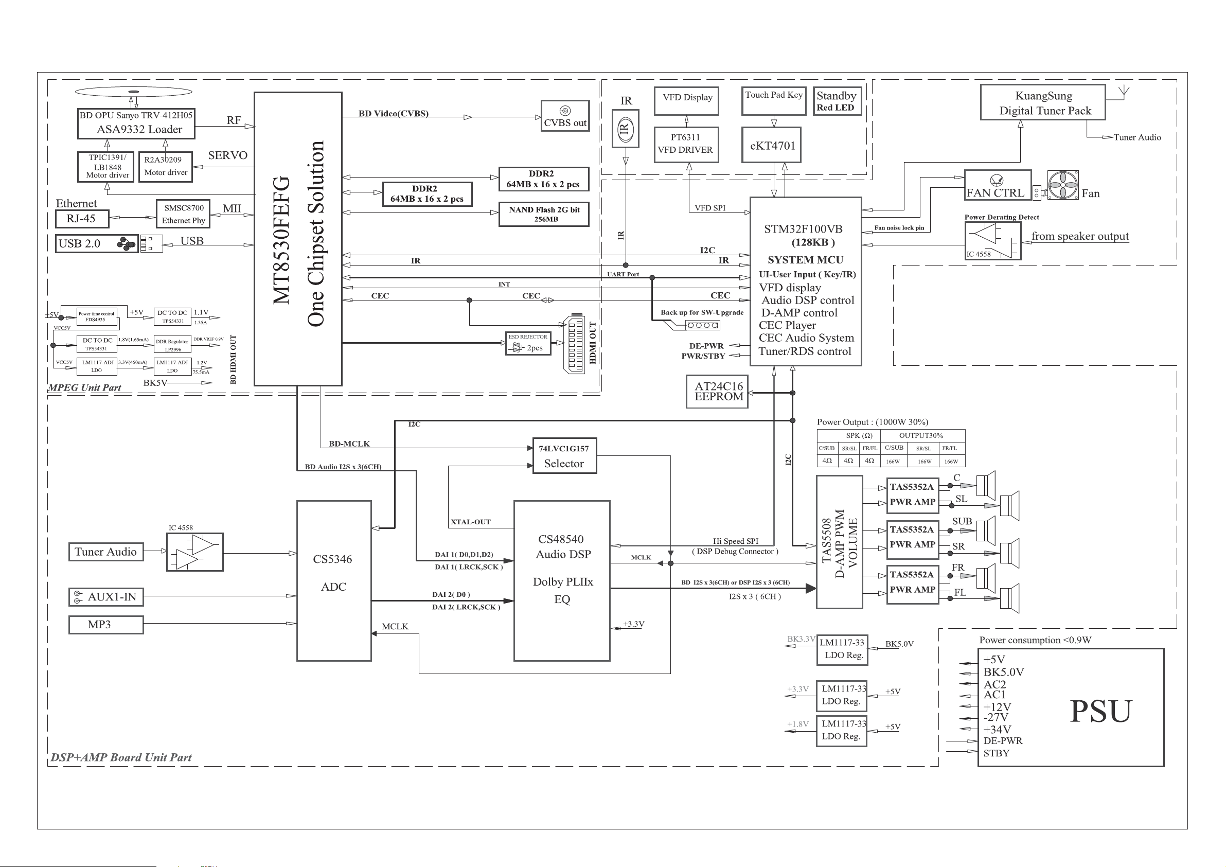
BLOCK DIAGRAM
4 - 1 4 - 1

WIRING DIAGRAM
4 - 2 4 - 2
V3
V7
V4
V8
V5
V2
V1
V6
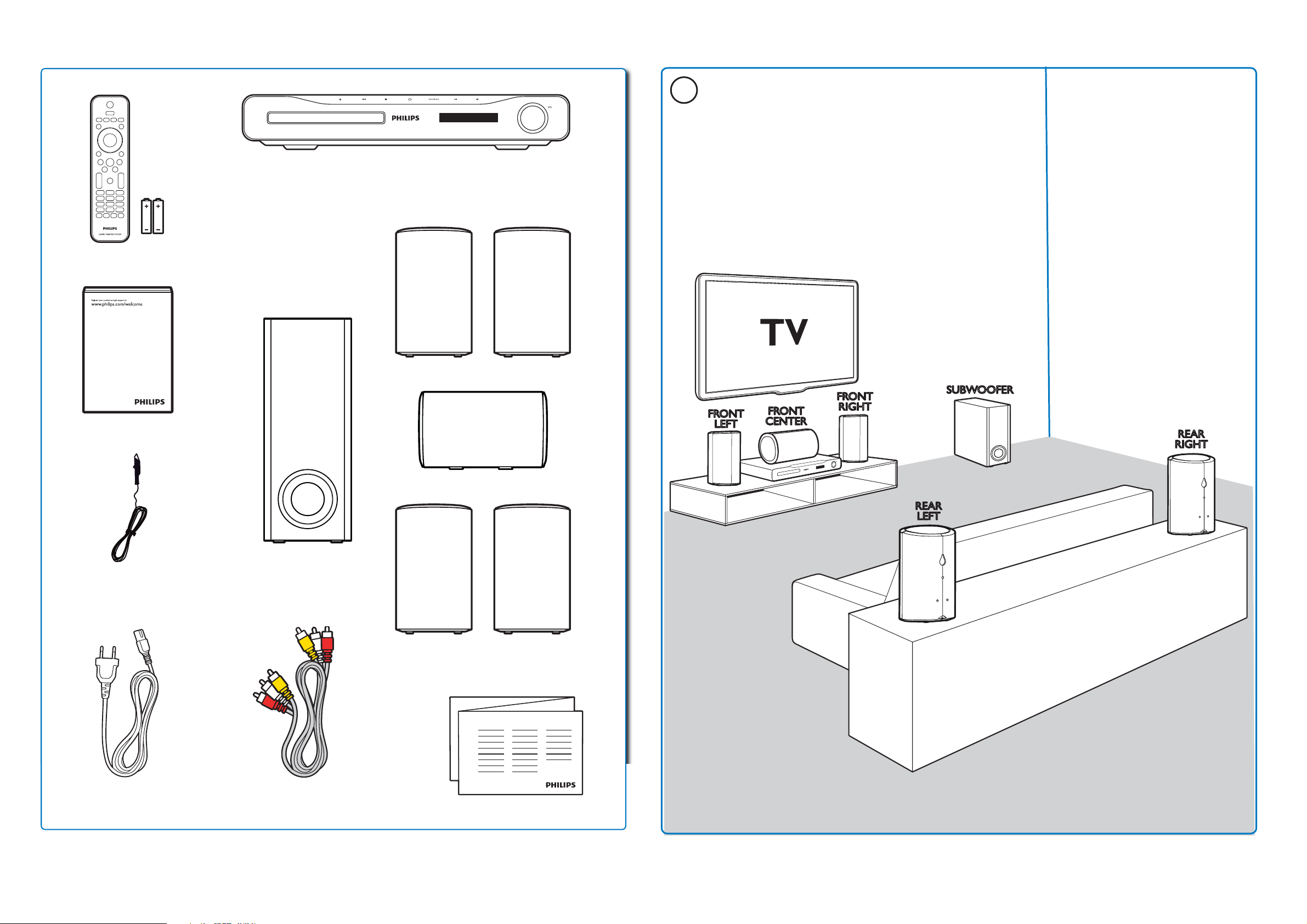
QUICK START GUIDE
SUBWOOFERSUBWOOFER
REAR
LEFT
REAR
LEFT
REAR
RIGHT
REAR
RIGHT
FRONT
CENTER
FRONT
CENTER
FRONT
LEFT
FRONT
LEFT
FRONT
RIGHT
FRONT
RIGHT
User Manual
5 - 1 5 - 1
1
FM Antenna
Power cord
Audio/Video
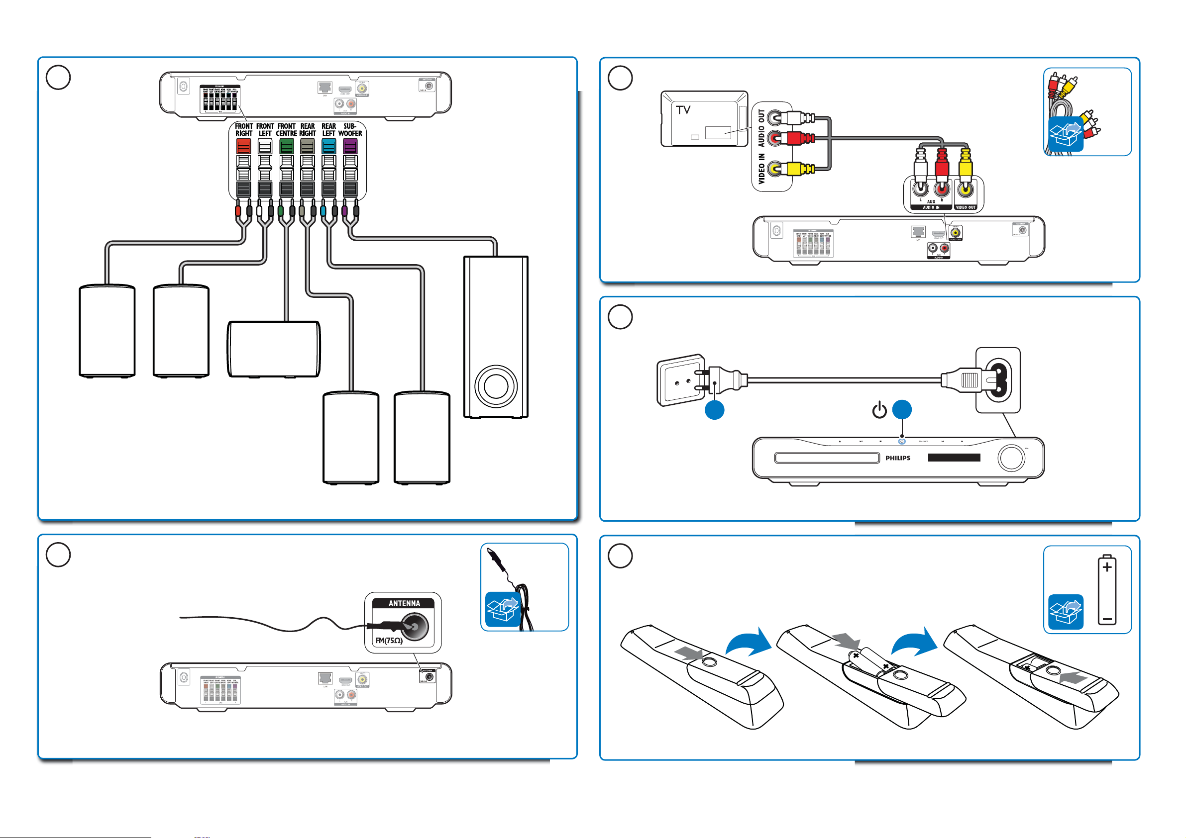
5 - 2 5 - 2
SUBWOOFER
REAR
LEFT
REAR
RIGHT
FRONT
RIGHT
FRONT
LEFT
FRONT
CENTER
2
4
5
Audio/
Video
Cable
3
FM
Antenna
6
1
2
AAA
x 2
 Loading...