

Philips HTRM800-AED Datasheet

INTEGRATED CIRCUITS
DATA SH EET
HTRM800 family
HITAG long range reader module
hardware
Product specification
Supersedes data of 1999 Jan 01
File under Integrated Circuits, IC11
2001 Oct 04

Philips Semiconductors Product specification
HITAG long range reader module
hardware
CONTENTS
1 FEATURES
2 APPLICATIONS
3 GENERAL DESCRIPTION
4 ORDERING INFORMATION
5 BLOCK DIAGRAM
6 PINNING
6.1 ST1 connector
6.2 ST2 connector
7 FUNCTIONAL DESCRIPTION
7.1 System overview
7.1.1 Transponders
7.1.2 Antenna
7.1.3 Host system
7.1.4 I/O functions
7.1.5 Power supply
7.2 Reader module software
7.3 Reader module hardware
7.3.1 Microcontroller
7.3.2 Interface microcontroller to host
7.3.3 Transmitting part
7.3.4 Receiving part
7.3.5 Digital signal processing unit
7.3.6 Periodic disturbers
7.3.7 Voltage regulating unit
7.3.8 Standby mode
7.3.9 Behaviour with HITAG 1 transponders
7.3.10 Behaviour with HITAG 2 transponders
7.4 Postal approval
7.5 Operating security
7.5.1 Anticollision mode
7.5.2 Monitoring the supply voltage
7.5.3 Antenna rupture and antenna short-circuit
7.6 Security considerations
7.6.1 Data privacy
HTRM800 family
8 ELECTRICAL SPECIFICATIONS
9 MECHANICAL SPECIFICATIONS
10 APPLICATION INFORMATION
10.1 Metallic environment and interferences
10.2 Distance between two antennas
10.3 External power supply
10.4 Possible sources of errors by connecting the
HTRM800
10.5 Building HITAG long range antennas
10.5.1 Basics
10.5.2 Recommended antenna cable and length
10.5.3 Tuning of the antenna current
10.5.4 Tuning of the antenna phase
10.5.5 HITAG antenna tuning device
10.5.6 Antenna malfunction indication
10.5.7 Additional remarks
10.6 Antenna arrangements
11 SURVEY OF REFERENCED DOCUMENTS
12 DATA SHEET STATUS
13 DEFINITIONS
14 DISCLAIMERS
2001 Oct 04 2

Philips Semiconductors Product specification
HITAG long range reader module
hardware
1 FEATURES
• Multi-tag operation (anticollision)
• Read and write distances up to 1000 mm
• Digital signal processor to reduce noise sensitivity
• Communication with all HITAG transponders and
various other 125 kHz transponders
• Data encryption and key handling
• Easy system integration
• Three interface options
• Meets all requirements for CE and EMI approval.
2 APPLICATIONS
• Universal and flexible reader module for long range
systems.
3 GENERAL DESCRIPTION
(1)
HITAG
product lines of our 125 kHz family. The contactless read
and write system that works with passive transponders is
suitable for various applications.
is the nameof one of the universal and powerful
HTRM800 family
Inductive coupling helps you to achieve operating ranges
up to 1000 mm and the use of cryptography guarantees
highest data security.
Anticollision mode, which is used only in long range
operation, allows you to handle several transponders that
are within the communication field of the antenna at the
same time, thus achieving highest operating security and
permitting to handle several data transfers quickly and
simultaneously. In this context anticollision becomes an
essential element of applications such as ski-ticketing and
long range access control. With applications of that type it
will always happen that several transponders arrive in the
communication field of the antenna at the same time.
(1) HITAG - is a trademark of Philips Semiconductors
Gratkorn GmbH.
4 ORDERING INFORMATION
PART NUMBER NAME ORDER CODE (12NC)
HTRM800/AED HITAG long range reader module RS232 9352 338 40122
HTRM800/CED HITAG long range reader module RS485 9352 338 50122
HTRM800/EED HITAG long range reader module CMOS 9352 338 60122
2001 Oct 04 3
Philips Semiconductors Product specification
HITAG long range reader module
hardware
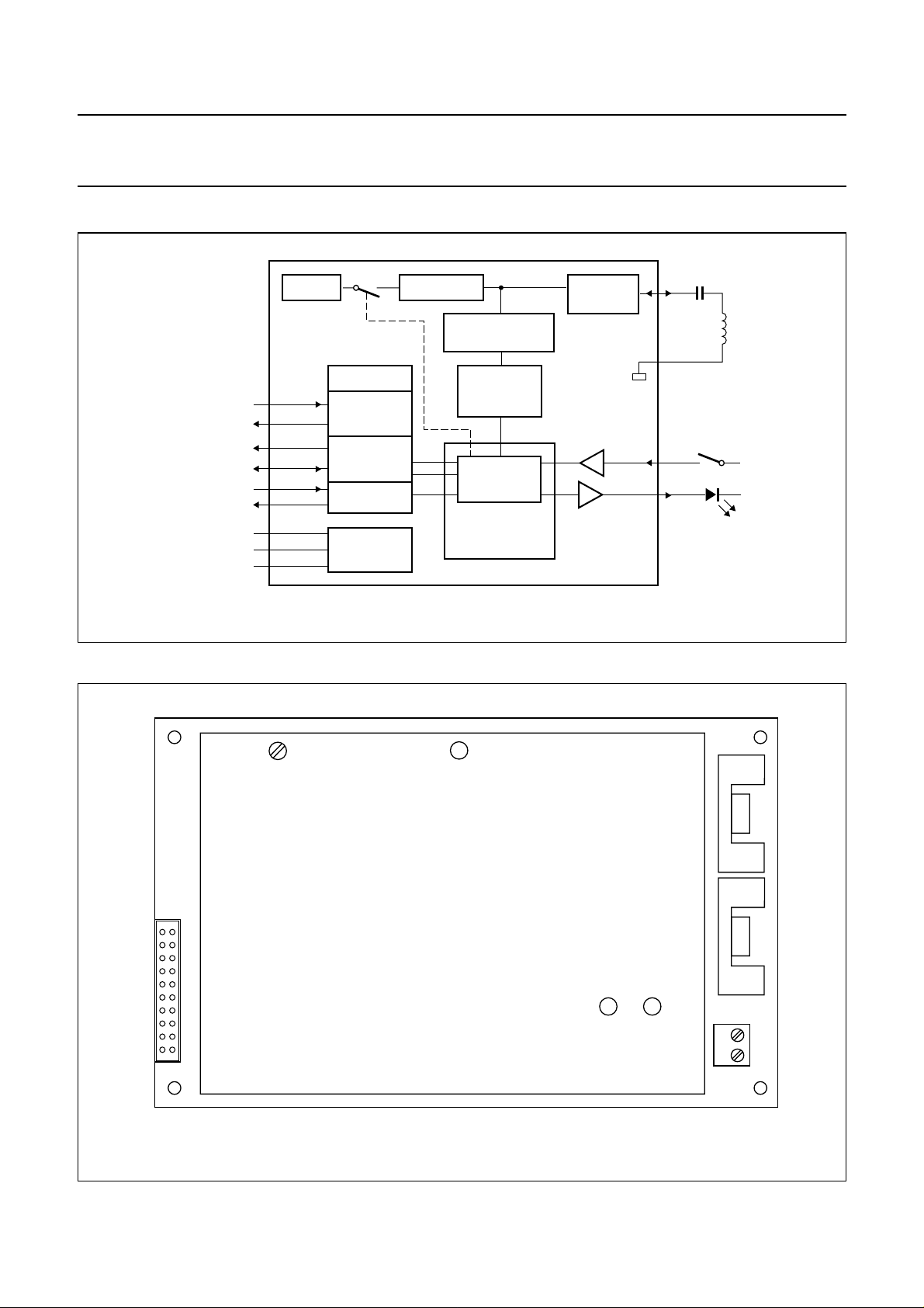
5 BLOCK DIAGRAM
handbook, full pagewidth
125 kHz
LINE DRIVER
CMOSIN
CMOSOUT
INT1
INT2
RXD
TXD
+15 V IN
GND
−15 V IN
CMOS
OPTIONAL
RS485
OPTIONAL
RS232
VOLT AGE
REGULATOR
AMPLIFIER
DEMODULATOR
CORE MODULE
FILTER
DIGITAL
SIGNAL
PROCESSOR
MICRO-
CONTROLLER
HTCM400
VOLT AGE
LIMITER
HTRM800
HTRM800 family
ANT
C
L
GND
antenna
CMIN
CMOUT
MGU417
6 PINNING
handbook, full pagewidth
ST1
10
1
Fig.1 Block diagram.
R72
11
20
HTRM800
ST2
21ANT
GND
Fig.2 Pin assignment.
2001 Oct 04 4
MGU418

Philips Semiconductors Product specification
HITAG long range reader module
HTRM800 family
hardware
6.1 ST1 connector
SYMBOL PIN TYPE
−15VIN 1 P DC supply voltage (−15 V)
GND 2 P ground
+15VIN 3 P DC supply voltage (+15 V)
GND 4 P ground
RXD 5 I serial interface input; RS232 level
GND 6 P ground
CMOSIN 7 I serial interface input; CMOS level (optional)
INT1 8 I/O serial interface input and output 1; RS485 level (optional)
CMIN 9 I core module input; general purpose
CMOUT 10 O core module output; general purpose
GND 11 P ground
GND 12 P ground
INT2 13 I/O serial interface input and output 2; RS485 level (optional)
CMOSOUT 14 O serial interface output; CMOS level (optional)
GND 15 P ground
TXD 16 O serial interface output; RS232 level
GND 17 P ground
+15VIN 18 P DC supply voltage (+15 V)
GND 19 P ground
−15VIN 20 P DC supply voltage (−15 V)
(1)
DESCRIPTION
Note
1. P = power supply, O = output and I = input.
6.2 ST2 connector
SYMBOL PIN DESCRIPTION
GND 1 ground
ANT 2 antenna output and input
2001 Oct 04 5
Philips Semiconductors Product specification
HITAG long range reader module
hardware
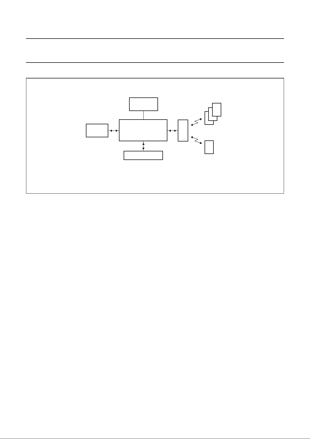
7 FUNCTIONAL DESCRIPTION
handbook, full pagewidth
HOST
SYSTEM
POWER
SUPPLY
antenna
HTRM800
I/O FUNCTIONS
Fig.3 System overview.
HTRM800 family
HITAG 1
transponders
HITAG 2
transponder
MGU419
7.1 System overview
The HITAG long range reader module (see Fig.3) is a part
of a complete Radio Frequency Identification (RFID)
system which consists of:
• Transponders
• Antenna
• Host system
• I/O functions
• Power supply.
7.1.1 TRANSPONDERS
TheHTRM800cancommunicatewithtranspondersbased
on Philips HITAG 1 and HITAG 2.
7.1.2 ANTENNA
The antenna is an important part of the HITAG long range
system. The antenna must provide energy and data
transmissionbetween the reader moduleand transponder.
7.1.3 HOST SYSTEM
The connection to the host system (e.g. microcontroller
or PC) is a serial interface on RS232 level for data
transmission.
7.1.4 I/O FUNCTIONS
One line of the HTRM800 is wired as input from e.g. a
switch and one line as output to drive a LED.
7.1.5 POWER SUPPLY
The HTRM800 must be supplied from an external power
supply with +15 V and −15 V (see Section 10.3).
7.2 Reader module software
Software command names mentioned in this data sheet
are fully described in document
“HTCM400, HTRM440
Family, HTRM800 Family Interface Protocol Reader Host”
.
7.3 Reader module hardware
7.3.1 MICROCONTROLLER
The microcontroller is placed on the HITAG core module
(see Fig.1) and processes the protocol for the
communication between the transponders and the reader
module. The interface signals are converted so that the
transponders are able to process them and the outgoing
signals from the transponders are converted into
interface-compatible signals.
The second essential microcontroller function is its control
function.Themicrocontrolleractivatesand deactivates the
transmitter and switches the receiver between the modes
for the different transponders reception.
Additional functions of the microcontroller are controlling
the standby mode of the amplifier, detection of detuned or
broken antennas (antenna malfunction) and controlling of
the input and output for general purpose.
2001 Oct 04 6
 Loading...