

Philips HTR HTR5000, HTR5000/01 User Manual
DIGITAL A/V SURROUND RECEIVER
User manual
Thank you for choosing Philips.
Need help fast?
Read your Quick-Use Guide and/or User Manual first for quick
tips that make using your Philips product more enjoyable.
If you have read your instructions and still need assistance,
you may access our online help at www.philips.com/support
HTR5000
2
8239 300 38591
Important notes for users in the
U.K.
Mains plug
This apparatus is fitted with an approved 13
Amp plug. To change a fuse in this type of plug
proceed as follows:
1 Remove fuse cover and fuse.
2 Fix new fuse which should be a BS1362 5
Amp, A.S.T.A. or BSI approved type.
3 Refit the fuse cover.
If the fitted plug is not suitable for your socket
outlets, it should be cut off and an appropriate
plug fitted in its place.
If the mains plug contains a fuse, this should
have a value of 5 Amp. If a plug without a fuse
is used, the fuse at the distribution board
should not be greater than 5 Amp.
Note: The severed plug must be disposed of to
avoid a possible shock hazard should it be
inserted into a 13 Amp socket elsewhere.
How to connect a plug
The wires in the mains lead are coloured with
the following code: blue = neutral (N),
brown = live (L).
¶ As these colours may not correspond with the
colour markings identifying the terminals in
your plug, proceed as follows:
– Connect the blue wire to the terminal
marked N or coloured black.
– Connect the brown wire to the terminal
marked L or coloured red.
– Do not connect either wire to the earth
terminal in the plug, marked E (or e) or
coloured green (or green and yellow).
Before replacing the plug cover, make certain
that the cord grip is clamped over the sheath
of the lead - not simply over the two wires.
Copyright in the U.K.
Recording and playback of material may
require consent. See Copyright Act 1956 and
The Performer’s Protection Acts 1958 to 1972.
Norge
Typeskilt finnes på apparatens underside .
Observer: Nettbryteren er sekundert
innkoplet. Den innebygde netdelen er
derfor ikke frakoplet nettet så lenge
apparatet er tilsluttet nettkontakten.
For å redusere faren for brann eller elektrisk
støt, skal apparatet ikke utsettes for regn eller
fuktighet.
Italia
DICHIARAZIONE DI CONFORMITa’
Si dichiara che l’apparecchio HTR5000 PHILIPS
risponde alle prescrizioni dell’ar t. 2 comma 1 del
D.M. 28 Agosto 1995 n. 548.
Fatto a Eindhoven
Philips Consumer Electronics
Philips, Glaslaan 2
5616 JB Eindhoven, The Netherlands
CAUTION
Use of controls or adjustments or
performance of procedures other
than herein may result in hazardous
radiation exposure or other unsafe
operation.
VAROITUS
Muiden kuin tässä esitettyjen
toimintojen säädön tai asetusten
muutto saattaa altistaa vaaralliselle
säteilylle tai muille vaarallisille
toiminnoille.
This AV Receiver is in
conformity with the EMC
directive and low-voltage
directive.
3
English
Français
Español
Nederlands
Italiano
Deutsch
8239 300 38591
Manufactured under license from Dolby
Laboratories. “Dolby”, “Pro Logic” and
the double-D symbol are trademarks of
Dolby Laboratories.
Manufactured under license from Digital
Theater Systems, Inc. U.S. Pat. No’s.
5,451,942; 5,956,674; 5,974,380; 5,978,
762; 6,226,616; 6,487,535 and other U.S.
and world-wide patents issued and
pending. “DTS” and “DTS Digital
Surround” are registered trademarks of
Digital Theater Systems, Inc. Copyright
1996, 2003 Digital Theater Systems, Inc.
All Rights Reversed.
This product complies with the radio
interference requirements of the
European Community.
Index
English ------------------------------------------------ 4
Français -------------------------------------------- 23
Español --------------------------------------------- 42
Deutsch --------------------------------------------- 61
Nederlands ---------------------------------------- 80
Italiano ---------------------------------------------- 99

English
4
8239 300 38591
General Information
Supplied accessories ............................................ 5
Care and safety information .............................. 5
Connections
Step 1: Set up the speakers................................ 6
Step 2: Placing the speakers and subwoofer .. 6
Step 3: Connecting speakers and subwoofer 7
Step 4: Connecting FM/MW antennas ............ 8
Step 5: Connecting the power cord ................ 8
Optional Connections - Playback
Connecting to TV/VCR/other audio
devices .................................................................... 9
Connecting to a DVD/SACD player .............. 10
Option 1: Using 6 Channel In jacks.......... 10
Option 2: Using Coaxial In jack ................ 10
Option 3: Using Optical In jack................. 10
Optional Connections - Recording
Connecting to a recording device.................. 11
Functional Overview
Main unit and remote control......................... 12
Control buttons available on the
remote only ................................................... 13
Getting Started
Step 1: Inserting batteries into the
remote control ................................................... 14
Using the remote control to operate
the system ...................................................... 14
Step 2: Switching On/Off.................................. 14
Switching to an active mode ...................... 14
Switching to standby mode ........................ 14
Step 3: Setting the speakers...................... 14–15
Adjusting the speaker output levels......... 15
Sound Controls
Selecting surround sound................................. 16
Selecting digital sound effects.......................... 16
Adjusting the Bass/Treble level........................ 16
Volume Controls and Other
Features
Volume Control .................................................. 17
Night Mode - turning on/off ............................ 17
Dimming system’s display screen.................... 17
Setting the Sleep Timer ..................................... 17
Tuner Operations
Tuning to radio stations .................................... 18
Presetting radio stations................................... 18
Automatic presetting................................... 18
Manual presetting ......................................... 18
Selecting a preset radio station....................... 19
Tr oubleshooting .........................................20
Specifications ............................................... 21
Glossary ........................................................ 22
Contents
English
5
8239 300 38591
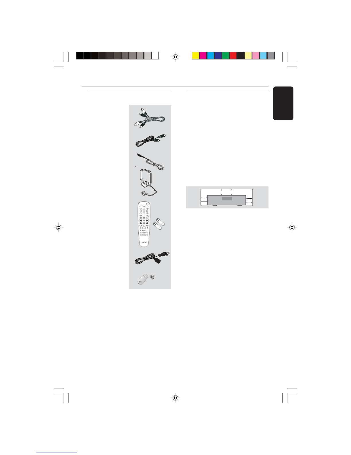
Supplied accessories
General Information
Audio cables
(red, white)
Coaxial cable
FM wire antenna
MW loop antenna
Remote control and
two batteries
Power cable
Speaker brackets
and screws
Care and safety information
Avoid high temperatures, moisture,
water and dust
–Apparatus shall not be exposed to
dripping or splashing.
– Do not place any sources of danger on
the apparatus (e.g. liquid filled objects,
lighted candles).
Do not block any ventilation
openings
– Place the apparatus in a location with
adequate ventilation to prevent internal
heat build up. Allow at least 10cm
(4 inches) of free space all around the
apparatus for adequate ventilation.
Finding a suitable location
– Place the player on a flat, hard, stable
surface.
– Do not position the set on top of
other equipment that might heat it up (e.
g. DVD player or amplifier).
Care of the cabinet
– Use a soft cloth slightly moistened
with a mild detergent solution. Do not
use a solution containing alcohol, spirits,
ammonia or abrasives.
10 cm
(4 inches)
10 cm
(4 inches)
10 cm
(4 inches
)
DVD Home Cinema System
PHILIPS
(5x)
TV
DISC TUNER AUX
DVD MENU
DISC
SYSTEM
VOL
PLAY/PAUSE
STOP RESUME
SUBW REARCENTER TV VOL
REPEAT REPEAT SLEEP DIM
SURROUNDSOUND NIGHT MUTE
English
6
8239 300 38591
Connections
1
1
3
3
2
4
2
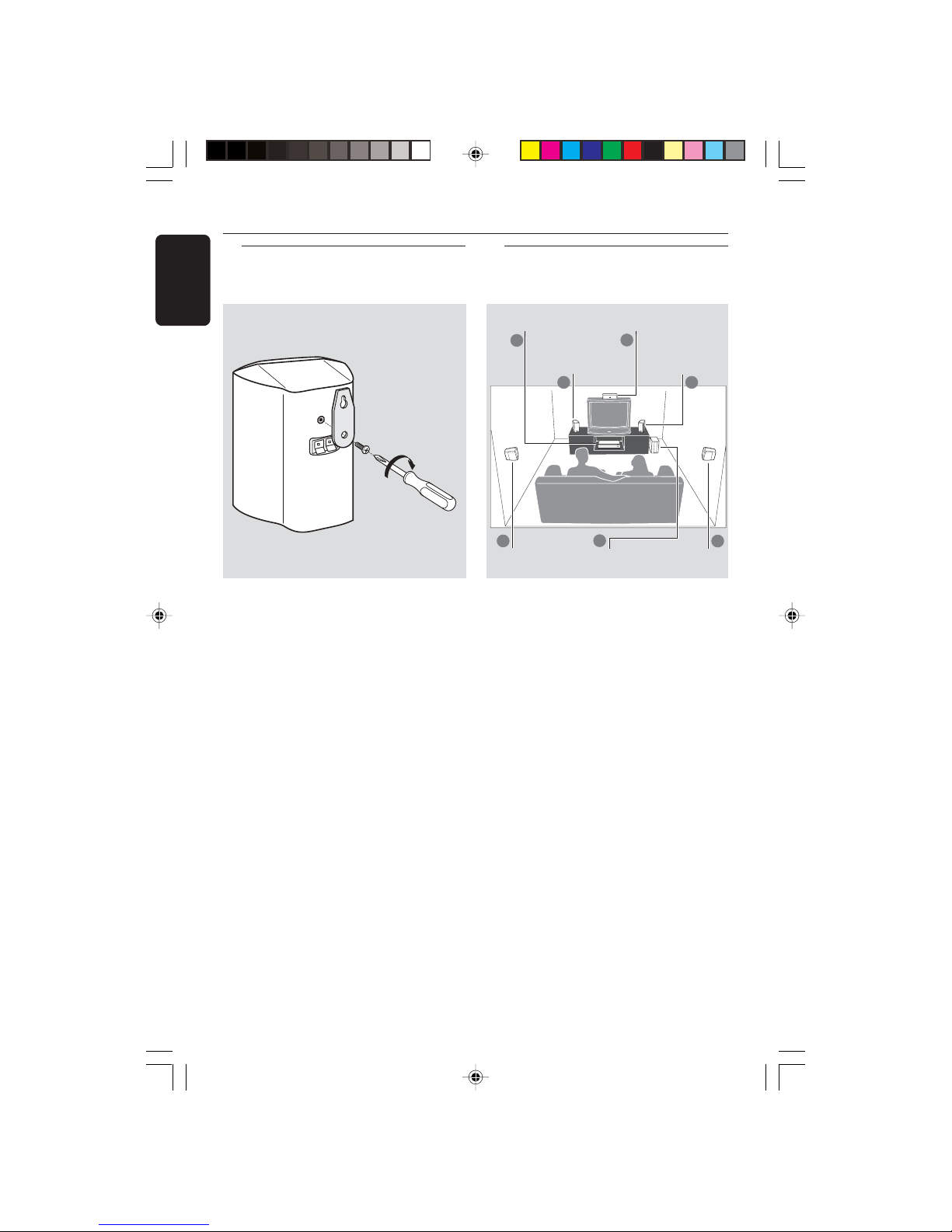
Step 2: Placing the speakers
and subwoofer
Front Speaker
(Left)
Front Speaker
(Right)
AV Receiver
Subwoofer
Rear speaker
(Right)
Rear speaker
(Left)
Centre
speaker
You can choose to hang the speakers on
the wall. Attach the supplied bracket
firmly to the rear of speakers using the
supplied screws. Then mount a screw
(not supplied) on the wall where the
speaker is to be hung and hook the
speaker securely onto the mounted
screw.
CAUTION!
You should get a qualified person to
attach the brackets to the wall. DO
NOT do it by yourself to avoid
unexpected damage to the
equipment or injury to personnel.
Helpful Hints:
– The rear speakers are labelled as REAR L
(left) or REAR R (right).
– The front speakers are labelled as
FRONT L (left) or FRONT R (right).
Step 1: Set up the speakers
For best possible surround sound, all the
speakers (except subwoofer) should be
placed at the same distance from the
listening position.
1 Place the front left and right speakers at
equal distances from the TV and at an
angle of approximately 45 degrees from
the listening position.
2 Place the centre speaker above the TV or
the AV receiver so that the centre
channel’s sound is localised.
3 Place the rear speakers at normal
listening ear level facing each other or
mounted on the wall.
4 Place the subwoofer on the floor near
the TV.
Helpful Hints:
–To avoid magnetic interference, do not
position the front speakers too close to your
TV.
– Allow adequate ventilation around the AV
receiver.
English
7
8239 300 38591
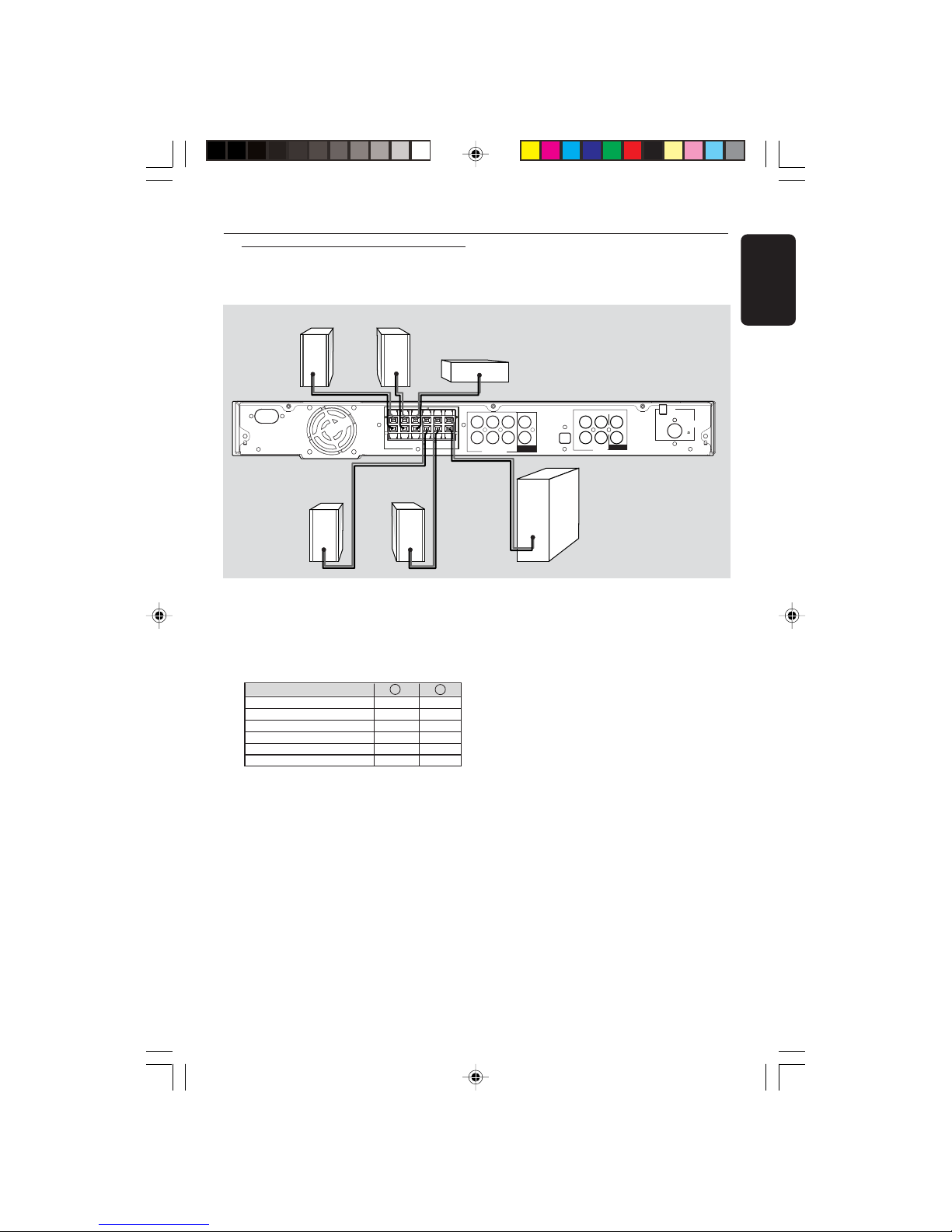
Step 3: Connecting speakers
and subwoofer
Front Right
Rear Right Rear Left
Centre
Connections
Subwoofer
Front Left
● Connect the supplied speaker systems by
matching the colours of the jacks and
speaker cables. Fully insert the stripped
portion of the speaker wire into the
jacks.
Speakers / Subwoofer - +
FRONT LEFT (FL) black white
FRONT RIGHT (FR) black red
FRONT CENTER (FC) black green
REAR LEFT (RL) black blue
REAR RIGHT (RR) black gray
SUBWOOFER (SUBW) black purple
Helpful Hints:
– Ensure that the speaker cables are
correctly connected. Improper connections
may damage the system due to short-circuit.
– Do not connect more than one speaker to
any one pair of +/- speaker jacks.
– Do not connect speakers with an
impedance lower than the speakers supplied.
Please refer to the SPECIFICATIONS section
of this manual.
(75 )
L
L
R
++
( )
SPEAKERS 3
SPEAKERS 3
FRONT
RIGHT
FRONT
LEFT
REAR
LEFT
REAR
RIGHT
FRONT
CENTER
SUB-
WOOFER
FRONT RIGHT
FRONT LEFT
REAR RIGHT
REAR LEFTFRONT CENTER
SUBWOOFER
6 CHANNEL IN
COAXIAL IN
OPTICAL IN
AUX TV
AUDIO
ANTENNA
MW
FM
AC MAINS
IN OUT
COAXIAL OUT
 Loading...