

Philips HP L1502, HP L1523, Compaq fp5315, AJ6S40/02, AJ2S4M/02 Service Manual
...
15" TFT LCD Colour Monitor
Horizontal frequencies
47 - 63 kHz
Service
Service
Service
TABLE OF CONTENTS
SAFETY NOTICE
Published by BCU Monitor Printed in Taiwan Copyright reserved Subject to modification Sep. 10 2003
GB
3138 106 10308
Compaq fp5315
AJ2S4M/02
w/ audio
XH3 HP 15”
Important Safety Notice .................................. 2
Technical Data & Power Management.............. 3
Factory Mode .......................................... ...... 8
............................................10
Definition of Pixel Defects.............................. 13
Mechanical Instructions .................................14~15
Connecting to PC & the Monitor Front panel......4
OSD manu ..................................................... 5
Warning Message......... ..................................6
OSD Aging Mode & Lock/unlock.......................7
Failure mode of LCD panel...............................9
Troubleshooting
Wiring Diagram..............................................11
Flat Panel Adjust ...........................................12
Safety Test Requirements ..............................16
Electrical Instructions............................. .......17
Display Adjustment........................................18~19
DDC Instructions and DDC Data .................... 20~25
ISP Instruction...............................................26
Repair Flow Chart...........................................27~29
Repair tips .....................................................30
~32
D-SUB / DVI Diagram .....................................33
ROM Diagram ................................................34
Scaler Diagram ..............................................35~36
Control board Diagram and (C.B.A) ................ 39
Power board Diagram .................................... 40~41
Scaler board C.B.A-1&-2.................................44
Spare Parts List
Function Block Diagram..................................31
Power Diagram ..............................................37
Audio Diagram............................................... 38
Power board C.B.A.-1&-2................................42~43
Exploded View................................................45
Recommended Parts List & ....46~47
General product Specification ........................ 48~63
Different Parts List..........................................64~65
Description
Description
Page
Page
REFER TO BACK COVER FOR IMPORTANT SAFETY GUIDELINES
CAUTION: USE A SEPARATE ISOLATION TRANSFORMER FOR THIS UNIT WHEN SERVICING.
ANY PERSON ATTEMPTING TO SERVICE THIS CHASSIS MUST FAMILIARIZE HIMSELF WITH THE CHASSIS
AND BE AWARE OF THE NECESSARY SAFETY PRECAUTIONS TO BE USED WHEN SERVICING ELECTRONIC
EQUIPMENT CONTAINING HIGH VOLTAGES.
S
HP L1523
AJ6S4M/02
w/ audio
HP L1502
AJ6S40/02
w/o audio
IMPORTANT SAFETY NOTICE
2
9
Go to cover page
HP L1502
FOR PRODUCTS CONTAINING LASER :
DANGER- Invisible laser radiation when open.
AVOID DIRECT EXPOSURE TO BEAM.
CAUTION- Use of controls or adjustments or
performance of procedures other than
those specified herein may result in
hazardous radiation exposure.
CAUTION- The use of optical instruments with this
product will increase eye hazard.
TO ENSURE THE CONTINUED RELIABILITY OF THIS
PRODUCT, USE ONLY ORIGINAL MANUFACTURER'S
REPLACEMENT PARTS, WHICH ARE LISTED WITH THEIR
PART NUMBERS IN THE PARTS LIST SECTION OFTHIS
SERVICE MANUAL.
Proper service and repair is important to the safe, reliable
operation of all HPConsumer Electronics Company**
Equipment. The service procedures recommended by HP and
described in this service manual are effective methods of
performing service operations. Some ofthese service
operations require the use of tools specially designed for the
purpose. The special tools should be used when and as
recommended.
It is important to note that this manual contains various
CAUTIONS and NOTICES which should be carefully read in
order to minimize the risk of personal injury to service
personnel. The possibility exists thatimproper service
methods may damage the equipment. It is also important to
understand that these CAUTIONS and NOTICES ARE NOT
EXHAUSTIVE. HP could not possibly know, evaluate and
advise the service trade ofall conceivable ways in which
service might be done or of the possible hazardous
consequences of each way. Consequently, HP has not
undertaken any such broad evaluation. Accordingly, a
servicer who uses aservice procedure or tool which is not
recommended by HP must first satisfy himself thoroughly that
neither his safety nor the safe operation of the equipment will
be jeopardized by the service method selected.
* * Hereafter throughout this manual, HP Consumer
Electronics Company will bereferred to as HP.
WARNING
Critical components having special safety characteristics are
identified with a bythe Ref. No. in the parts list and
enclosed within a broken line*
(where several critical components are grouped in one area)
along with the safety symbol on the schematicsor
exploded views.
Use of substitute replacement parts which do nothave the
same specified safety characteristics may create shock, fire,
or other hazards.
Under no circumstances should the original design be
modified or altered without written permission from Philips.
Philips assumes no liability, express or implied, arising out of
any unauthorized modification of design.
Servicer assumes all liability.
* Broken Line
Take care during handling the LCD module with backlight
unit
- Must mount the module using mounting holes arranged infour
corners.
- Do not press on the panel, edge of theframe strongly or electric
shock as this will result in damage to the screen.
- Do not scratch orpress on the panel with any sharp objects, such
as pencil or pen asthis may result in damage to the panel.
- Protect the module from the ESD as it may damage the electronic
circuit (C-MOS).
- Make certain that treatment person s body are grounded through
wrist band.
- Do not leave the module in high temperature and in areas of high
humidity for a long time.
- Avoid contact withwater as it may ashort circuit within the module.
- If the surface ofpanel become dirty, please wipe it off with a soft
material. (Cleaning with a dirty or rough cloth may damage the
panel.)
HP L1502
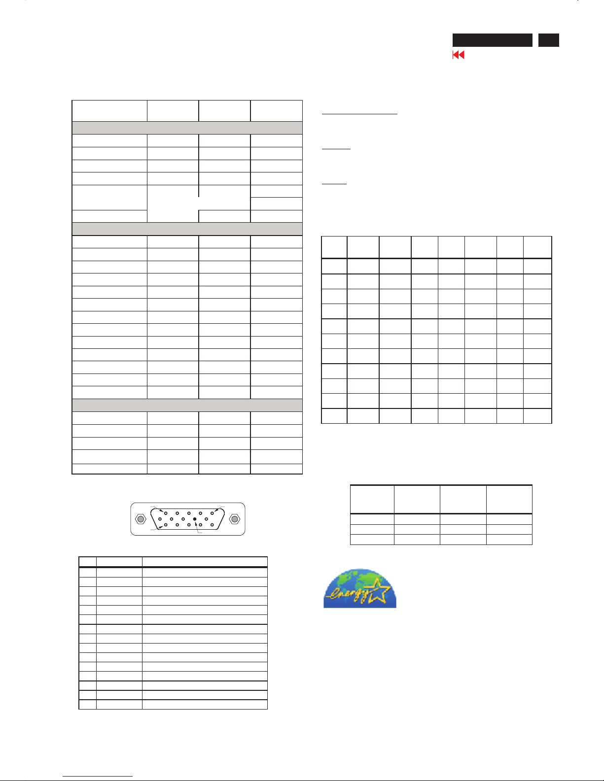
PIN MNEMONIC SIGNAL
1 RV Red Video
2 GV Green Video/Sync on Green
3 BV Blue Video
4 NC None
5 GND Ground (DDC Return) or Cable detect
6RGRedGND
7 GG Green GND
8BGBlueGND
9+5V+5V
10 SG Sync GND or Cable detect
11 NC None
12 SDA DDC Data
13 HS Horizontal Sync
14 VS Vertical Sync
15 SCL DDC Clock
CPU
State
Monitor
State
Maximum
Power
(Watts)
Power
Switch LED
Color
Full Power Full Power 25 Green
Sleep Sleep 2 Amber
- Switch Off 2 (LED off)
FACTORY PRESET DISPLAY MODES
Preset
Pixel
Format
Horz
Freq
(KHz)
Horz
Polarit
y
Vert
Freq
(Hz)
Vert
Polarity
Pixel
Clk
(MHz) Source
1 640 x
480
31.469 - 59.940 - 25.175 VGA
2 640 x
480
37.861 - 72.809 - 31.500 VESA
3 640 x
480
37.500 - 75.000 - 31.500 VESA
4 720 x
400
31.469 - 70.087 + 28.322 VGA
5 800 x
600
37.879 + 60.317 + 40.000 VESA
6 800 x
600
48.077 + 72.188 + 50.000 VESA
7 800 x
600
46.875 + 75.000 + 49.500 VESA
8 832 x
624
49.726 +/- 74.551 +/- 57.284 MAC
9 1024 x
768
48.363 - 60.004 - 65.000 VESA
10 1024 x
768
56.476 - 70.069 - 75.000 VESA
11 1024 x
768
60.023 + 75.029 + 78.750 VESA
3
Technical Specifications
Technical Data
Go to cover page
Pin Assignment:
ENERGY STAR is a U.S. registered mark. AS AN ENERGY STAR
PARTNER, DELL Computer Corporation HAS DETERMINED THAT
THIS PRODUCT MEETS THE ENERGY STAR GUIDELINES FOR
ENERGY EFFICIENCY.
Power management
Unit dimension / Weight
Set Dimension (incl. Pedestal): W340mm xD185.3mmxH338mm.
New weight: 3.6 Kg
Operating Temperature (Independent ofaltitude):5to35DegreeC.
Non-Operating Temperature (Independent of altitude): -20 to 60
DegreeC.
Operating (non-condensing) : 20%to 80%
Non-Operating (38.7Degree C maximum wet bulb temperature) :
5% to 90%
Operating :0 to 12,000feet [3,658 m].Equivalent to 14.7 to10.1 psia.
Non-Operating :0to 40,000 feet[12,192 m .Equivalent to 14.7 to 4.4
psia
Temperature Ranges
Humidity
Altitude
LCD
Vendor LGPL CPT QDI
Updated date 2002-Aug-30 2002-Dec.-13 200 3-June-02
Physical Dimension (mm)
Model Number LS150X05 CLAA150XG08 QD15X r01
Diagonal Size --- in ch 15.0" 15.0" 15.0"
Active Area (W x H ) 304.1x228.1 304 .1x228.1 304.1x228.1
Display Pixels (W x H ) 1024(x3) x 768 1024( x3) x 768 1024(x3) x 7 68
Pixel Pitch (0.099x3) x 0.297 (0.099x3) x 0.297 (0.099x3) x 0.297
Display Outline (W x H x T )
326.0x254.0x11.5
326.0x251.0x12 321x2 49x11
Weight 995 g 1100g 1200g
Optical Characteristics
Number of Colors 6 bits (262K) 6 bi ts (262K) 6 bits(262K )
Contrast Ratio 400(typ),250(min) 400(typ), 300(min) 400(ty p)
Viewing Angle (L/R) --- C/R>10 60/60(typ) 60/60(typ) 75/75(typ)
Viewing Angle (U/D) --- C/R>10 45/45(typ) 45/55(typ) 60/65(typ)
Luminance --- nits 250(typ),200(min) 250(typ), 200(min) 250(ty p),200(min)
White ( x , y ) 313 , 329 312, 318 313,329
Red ( x , y ) 626 , 347 643,344 637,340
Green ( x , y ) 308 , 588 304,566 302,582
Blue ( x , y ) 146 , 119 141, 85 146,97
Color Gamut -- % 59.5% 63% 62%
Luminance Uniformity (min) 75% 75% 75%
Backlight Life (min) 40K hrs 35Khrs 30Khrs
Crosstalk (max) 1.20% 1.5% 1.5%
Electrical Characteris tics
Supply Voltage 3.3V 3.3V ; 12V 3.3V
Operating Ambient Temp 0 ~ 50C 0 ~ 55C 0 ~ 50C
Power Consumption ( max) 10.4W 10.8W 11W
Main Clock (Typ~Max) 50~79MHz 50~79MHz 50~80MHz
Response time (Tr+Tf) 25ms(typ) 25ms(typ) 25ms(typ)
PIN 1
PIN 5
PIN 9
PIN 11
HP L1502
4
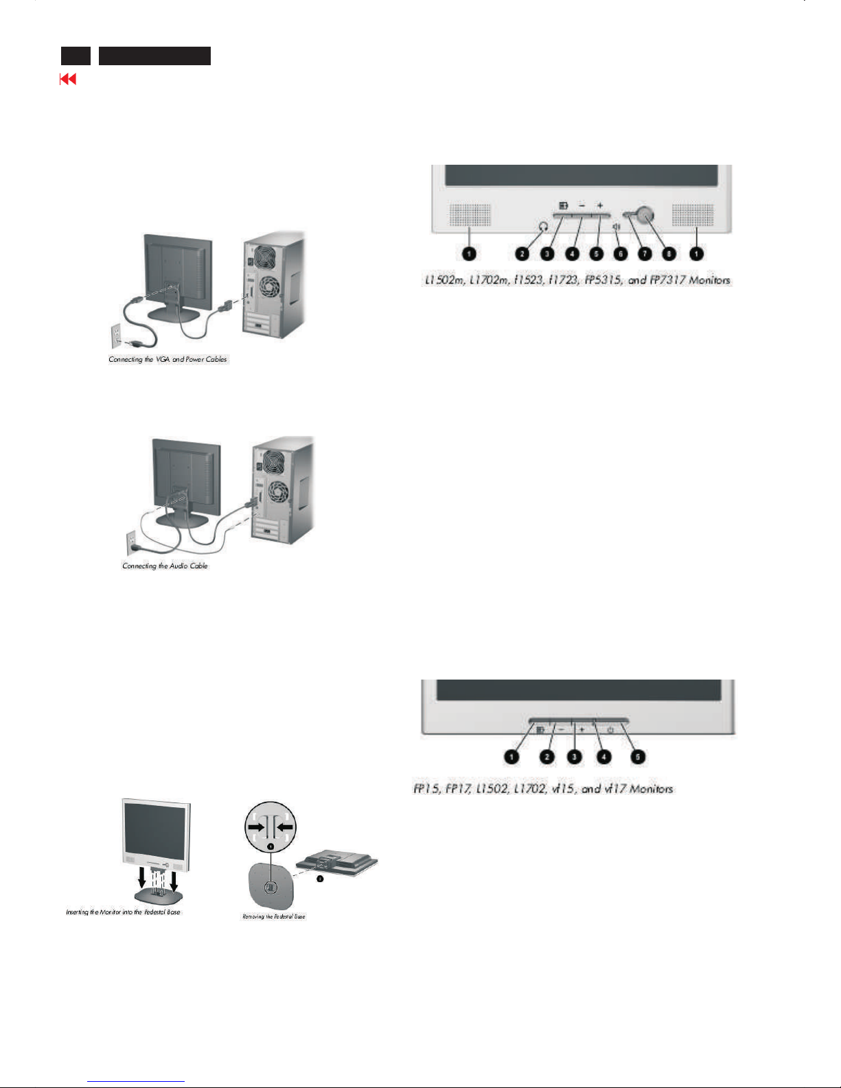
Connecting The Monitor
Go to cover page
Connecting to Your PC
1. Place the monitor in a convenient, well-ventilated location near your
computer.
2. Connect the monitor signal cable on the back of the monitor to the
video connector on the rear panel of the computer.
3. Connect one end of the power cable to the back of the monitor, and
the other end to an electrical wall outlet.
4. If your monitor is a multimedia model, connect one end of the audio
cable to the back of the monitor, and the other end to the audio
Connector on the back of the computer.
Installing the Monitor Pedestal
To install the monitor pedestal:
1. Place the pedestal plate on your desktop or table and check to
be sure the arrow on the underside of the plate is facing forward.
Do not install the base if the monitor will be used on a wall, swing arm,
or other mounting fixture; instead see the section on “Mounting the
Monitor” in this chapter.
2. Using both hands, position the monitor over the pedestal base
and press down firmly to lock the pedestal base in place. When the
base locks, it will make a clicking sound. Make sure the pedestal base
is securely locked before continuingwith the setup.
If you need to remove the pedestal base, lay the monitor down on
a soft protected surface. On the bottom side of the pedestal base,
press together the two tabs as shown in the following illustration.
This will release the pedestal from the base.
Front Panel Components
1 Speakers Audio feature for music,alarms,etc.(multimedia models only)
2 (Headphone jack)Connects a headphone set to the monitor.
3 Menu button Launches the On-Screen Display (OSD) menu and
selects functions.
4 (Minus button) When OSD is inactive, auto-adjusts the screen
Image. When OSD is active, navigates in reverse through the OSD
and adjusts OSD scale settings.
5 + (Plus button) When the OSD is active, navigates through the OSD
and adjusts OSD scale settings.
6(Volume control)Controls the volume level of the monitor speakers.
7 Power LED Fully powered = Green.
Sleep mode = Amber.
Sleep Timer mode = Flashing Amber.
8 Power Switch Powers the monitor on and off.
No. Control Function
No. Control Function
1 Menu button Launches the On-Screen Display (OSD) menu and
selects functions.
2 (Minus button) When OSD is inactive, auto-adjusts the screen
image. When OSD is active, navigates in reverse through the OSD
And adjusts OSD scale settings.
3 + (Plus button) When the OSD is active, navigates through the OSD
and adjusts OSD scale settings.
4 Power LED Fully powered = Green.
Sleep mode = Amber.
Sleep Timer mode = Flashing Amber.
5 Power Switch Powers the monitor on and off.Number Control Function
HP L1502
5
Go to cover page
On-Screen Display
ADVANCED OSD MODE CONFIGURATION
Mode Menu
Menu Level 1 Menu Level 2 Menu Level 3 Factory Reset
Brightness ADJ Scale Y (FD = 100)
Contrast ADJ Scale Y ( FD = 50)
Image Control Auto Adjustment Show “Adjusting…” message Y (no FD)
Horizontal Position ADJ Scale Y (no FD)
Vertical Position ADJ Scale Y (no FD)
Clock ADJ Scale Y (no FD)
Clock Phase ADJ Scale Y (no FD)
Cancel
Save and Return
Color 9300 K
6500 K-sRGB Y (FD = 6500 K-
sRGB )
Custom Color R/G/B Color ADJ Y(FD =100)
Cancel
Save and Return
Language Deutsch
English N (FD=English)
Español
Français
Italiano
Nederlands
Cancel
Save and Return
Management Power Saver On / Off Selection N (FD=ON)
Power On Recall On / Off Selection N (FD=ON)
Mode Display On / Off Selection N (FD=OFF)
Sleep Timer Timer Set Menu N (FD=0;OFF)
Cancel
Save and Return
OSD Control Horizontal OSD
Position
ADJ Scale N (FD=50)
Vertical OSD
Position
ADJ Scale N (FD=50)
OSD Timeout ADJ Scale N (FD=30)
Cancel
Save and Return
Factory Reset Yes
No
Exit
Main manu
Brightness
Contrast
Image control
Color
Language
Management
OSD control
Factory reset
Exit
Pressing the Menu button ( ) the first time brings up the BASIC
menu level. The + and buttons move up and down the menu,
respectively. The selected menu function shall be highlighted in
orange text for all menus. Pressing the Menu button again brings up
the second menu level for the item selected. The selection will wrap
around if the bottom item is selected and the button is pressed, the
selection will move to the top item. Likewise, if the top item is
selected and the + button is pressed, the selection will move to the
bottom item. Selecting the “Advanced Menu” from the Basic Menu
will result in the display of the ADVANCED OSD. The Advanced
Menu will remain the default OSD upon subsequent power-ups of the
monitor until the “Basic Menu” option is selected or until “factory
reset” is selected.
HP L1502
6
Go to cover page
Warning message table
Warning message table
BASIC OSD MODE CONFIGURATION
Mode Menu
Menu Level 1 Menu Level 2 Menu Level 3 Factory Reset
Brightness ADJ Scale Y (FD = 100)
Contrast ADJ Scale Y ( FD = 50)
Auto Adjustment Show “Adjusting… ” message Y(noFD)
Advanced Menu Refer to table 8
Exit
Item Attention Signals Display Time Condition
1 Input Signal out of Range see power saver table
2 No Input Signal see power saver table
3 Going to Sleep see power saver table
4 Adjusting… .. The Minus ( " - " ) button shall be a hot-key for the Auto-Adjustment process.
Menu button ( ), shall be hot-key for OSD Menu Exit
5 OSD Lockout 10secs Push menu key for 10 sec then display 10 sec WM “OSD Lockout”
6 Check Video Cable see power saver table
Power Saver table
Power Saver - On Power Saver - Off Note
Quit signal with cable 1. System blank and show WM 1. System blank and show
"Going to Sleep" 3 sec then sleep. moving WM "No Input Signal" always.
Disconnect cable 1. System blank and show 1. System blank and show
WM “Check Video Cable”10 WM “Check Video Cable” 10
sec then moving about 50 sec. sec then moving always.
2. Show WM “Going to
Sleep” 3 sec then sleep.
3. If push any key in sleep
mode, then repeat item 1 to 2.
Out of range –1 1. System blank and show 1. System blank and show H<29.5 or
moving WM “Input Signal moving WM “ Input Signal H>82.5 or
out of Range” 60 secs. Out of Range”always. V<49 or
2. Show WM “Going to V>87 or
Sleep” 3 sec then sleep. Vtotal>=1200
3. If push any key in sleep
mode, then repeat item 1to 2.
Out of range –2 1. Show moving WM 1. Show moving WM DownScaling
"Input Signal out of Range" 60 sec. “Input Signal out of Range”60 sec. Ex.
2. Menu key can active 2. Menu key can active 1280x1024
during moving WM and during moving WM and
operate OSD menu. operate OSD menu.
3. WM disappear if menu 3. WM disappear if menu
key push or after WM 60 sec. key push or after WM 60 sec.
Out of range –3 1. Show moving WM 1. Show moving WM 85Hz
"Input Signal out of Range" 60 sec. “Input Signal out of Range”60 sec.
2.AftermovingWM60sec 2.AftermovingWM60sec
then show WM “Going to Sleep”3 sec then show WM “Going to
then sleep. Sleep” 3 sec then sleep.
3. If push any key in sleep 3. If push any key in sleep
mode, then repeat item 1 to 2. mode, then repeat item 1 to 2.
HP L1502
7
Go to cover page
OSD Lock/Unlock, Aging & ,
Enable/Disable "warning message"
ATTENTION
OSD LOCK OUT
Check Video Cable
To Lock/Unlock OSD function (User Mode)
-
The OSD function can be locked by pressing " " button(3) for
more than 10 seconds, the screen shows following windows for 3
seconds. Everytime when you press " " or"+"button, this
message appears on the fly screen automatically.
To Enable/Disable "Warning message" on screen
(in User Mode)
Unlock OSD function:
Locked OSD function can be released by pressing" " button for
more than 10 seconds again.
Step 1: Turn off LCD monitor, and disconnect Interface Cable
between Monitor and PC.
Step 1: Turn on LCD monitor, and disconnect Interface Cable
between Monitor and PC. bring up
Fig. 2
Bring up
After 15 seconds, bring up :
After 15 seconds, bring up :
:
After 15 seconds, bring up :
----------
---------repeatly
Connect signal cable again => go back to normal display.
Status 1.:
=> go back to Windows screen.
Connect signal cable again
Access Aging.. Mode
Step 2 :
[Push " " & " " buttons at the same time and hold it ] +
[Press power " " button untill comes out "AGING screen"
] => then release all buttons.
+
AGING...AGI N G ...
AGING...AGI N G ...
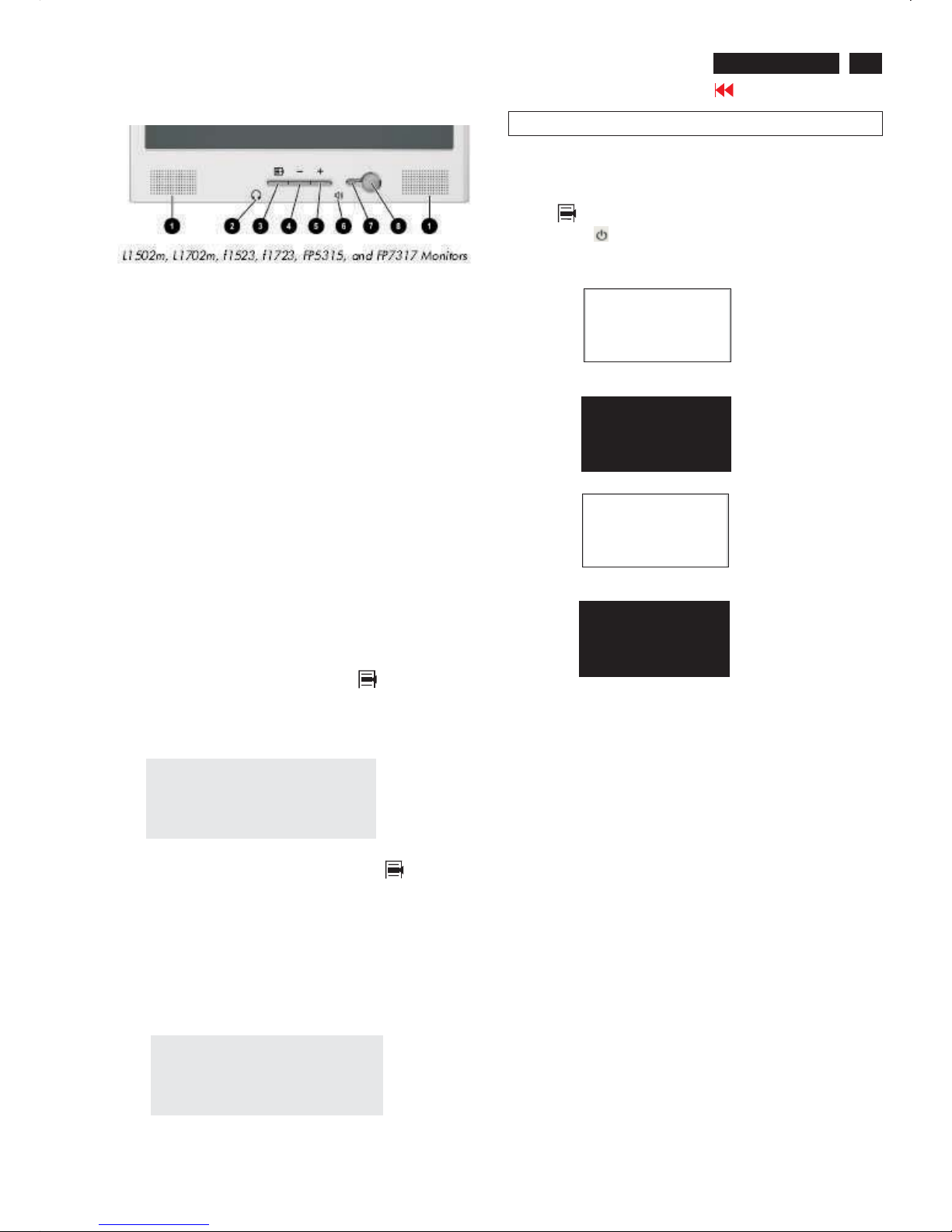
Front control panel
Fig. 1
1 Speakers Audio feature for music,alarms,etc.(multimedia models only)
2 (Headphone jack)Connects a headphone set to the monitor.
3 Menu button Launches the On-Screen Display (OSD) menu and
selects functions.
4 (Minus button) When OSD is inactive, auto-adjusts the screen
Image. When OSD is active, navigates in reverse through the OSD
and adjusts OSD scale settings.
5 + (Plus button) When the OSD is active, navigates through the OSD
and adjusts OSD scale settings.
6(Volume control)Controls the volume level of the monitor speakers.
7 Power LED Fully powered = Green.
Sleep mode = Amber.
Sleep Timer mode = Flashing Amber.
8 Power Switch Powers the monitor on and off.
No. Control Function
No. Control Function
HP L1502
Main manu
Brightness
Contrast
Image control
Color
Language
Management
OSD control
Factory reset
Exit F
8
Go to cover page
Factory mode
Access Factory Mode
Step 2 :
[Push " " & " " buttons at the same time and hold it ] +
[Press power " " button untill comes out "Windows screen"
] => then release all buttons.
+
How to Get into Factory Mode Menu
Turn off monitor.
Press OK " " button, bring up Factory mode indication as
shown in Fig 2.
Step 1 :
Step 3 :
Basic and simple instruction on the control keys.
When you press the button on the front control of your monitor, the OnScreen Display (OSD) Main Controls window will pop up and you can
then start making adjustments to your monitor's various features.
Front control panel
Fig. 1
Fig. 2
Contrast adjustment (Sub-Contrast). Use this menu item to
adjust the contrast gain of pre-amp ranges from 0 to 255.
9300KRGB
6500KRGB
Color temperature gain adjustment. Use these menu items to
adjust the RGB gains of pre-amp for different color
temperatures, ranges from 0 to 255.
OFFSET R G B
Sub-Brightness adjustment. Use this menu item to adjust
the brightness level (DC-level) of pre-amp range from 0 to
255.(R/G/B ANALOG DC -level).
GAIN R G B
R/G/B GAIN adjustment. Use this menu item to adjust
the R/G/B (GAIN) of Amp. range from 0 to 255.(R/G/B
ANALOG GAIN Values).
It is for 1024x768/60Hz with special pattern only.
AUTO SUB:
Do not use this function here.
AUTO SUB:
(PS: The OffsetRGB function can be used on reduce or eliminate
snowy noise on the background when the resolution of video signal is
1280 X 1024 vertical 60Hz. Slightly increase or decrease the value
until snowy noise completely disappear.)
Hot key function: by pressing "UP" and "DOWN" key
simultaneously at User mode (or Factory mode).
-
OK
-
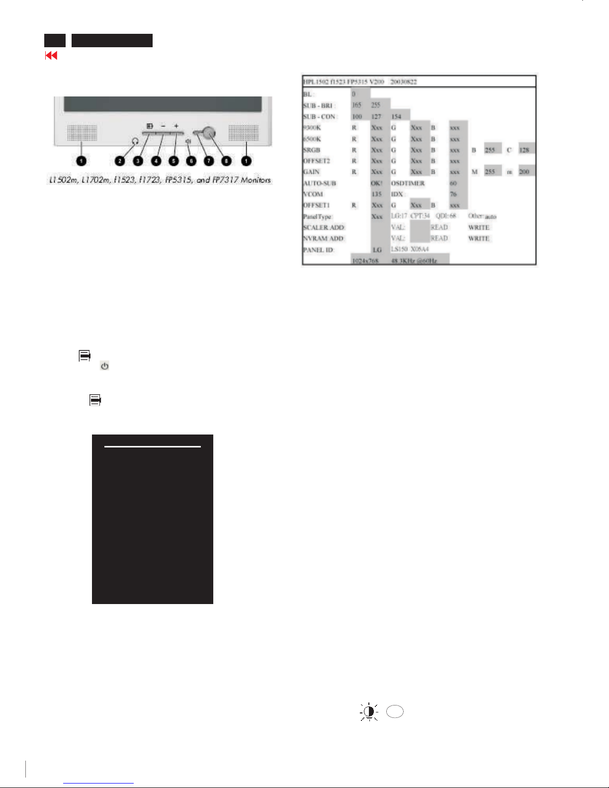
SUB CON:SUB CON:
BL : Blacklevel value
SUB-BRI : Brightness value range(Min Max). Fix value for
continue mode requirement.LG(Min=165, Max=255),
CPT(Min=165, Max=230), QDI(Min=165, Max=225).
SUB-CON : Contrast value range(Min Mid Max)
SRGB-B : Brightness of sRGB(Reserved)
SRGB-C : Contrast of sRGB(Reserved)
Gain-m : Minimum value of User Gain
Gain-M : Maximum value of User Gain
AUTO-SUB: To do Auto color function when push "Up" key in
White pattern
OSDTIMER : OSD time out control (sec) Unused in this project
VCOM : For LG panel control
IDX : Limit current of inverter(Fix value QDI: 76, CPT: 45, LG:5)
Panel Type: If set this to 17, 34 or 68 then system will force panel
type to LG, CPT or QDI. Set to other value will auto
detect panel based on panel hardware.
SCALER : Read/Write scaler register
NVRAM : Read/Write eeprom address
Factory menu
Cursor can move on gray color area
Fig. 3
<------Factory mode indicator
9
HP L1502
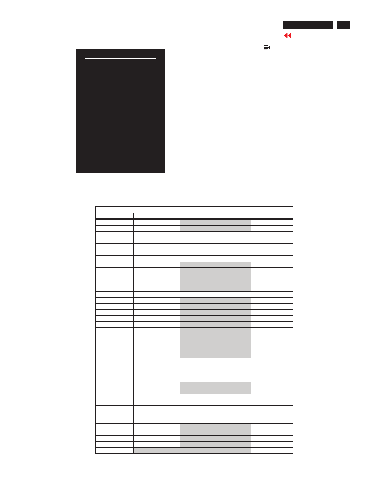
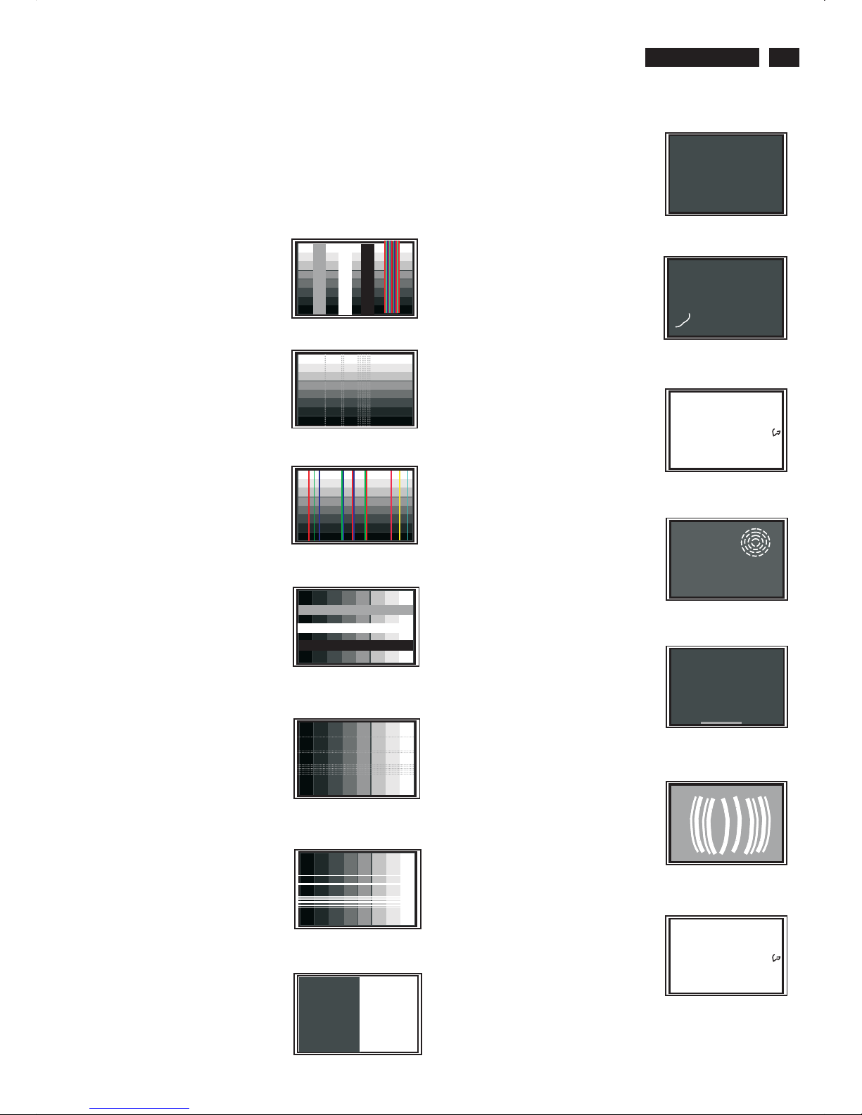
Failure Mode of LCD panel
Quick reference for failure mode of LCD panel
This page presents problems that could be made by LCD panel. It is
not necessary to repair circuit board. Simply follow the “Mechanical
instruction” on this manual to eliminate failure by replace LCD panel
or backlight tubes.
Failure description Phenomenon
Vertical dim lines
Vertical block defect
Vertical lines defect
(Always bright or dark)
Horizontal block defect
Horizontal dim lines
Horizontal lines defect
(Always bright or dark)
Has bright or dark pixel
.
..
.
.
.
.
..
.
.
.
Bright pixel
Dark pixel
..
. .. .
Polarizer has bubbles
Polarizer has bubbles
Foreign material inside
polarizer. It shows linear or
dot shape.
. .. .
Concentric circle formed
Bottom back light of LCD is
brighter than normal
Backlight un-uniformity
Backlight has foreign
material. Black or white
color, linear or circular type
9
Go to cover page

HP L1502
10
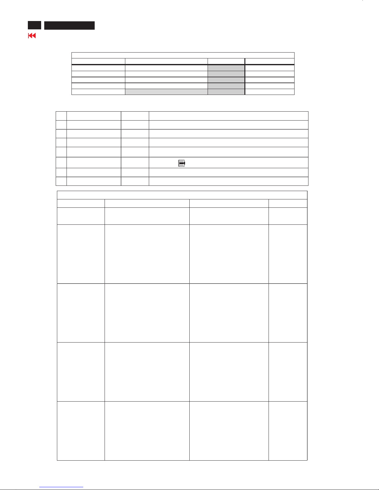
Troubleshooting
Go to cover page
Solving Common Problems
The following table lists possible problems, the possible cause of each problem, and the recommended solutions.
Screen is blank. Power cord is disconnected. Connect the power cord.
Power switch is turned Off. Turn on the power.
Video cable is improperly connected. Connect the video cableproperly.
Screen blanking utility is active. Depress any key on the keyboard or move
The mouse to inactivate the screen blanking
Utility.
Problem Possible Cause Solution
Image appears
blurred, indistinct, or
Too dark.
Image is not
Centered. auto-adjust the screen image.
Press the Menu button to access the
Advanced OSD menu. Select Image
Control/Horizontal Position or Vertical
Position to adjust the horizontal or vertical
position of the image.
Check Video
Cable is displayed
on screen.
(Input Signal Out of
Range) is displayed
on screen.
Restart your computer so that the
new settings take effect.
Brightness and contrast Press the Minus button on
are too low. the monitor front panel to
auto-adjust the screen. If that
Does not work, press the
Menu button to open the
Basic OSD Menu, and
adjust the brightness and
contrast scales as needed.
Position may need When OSD is inactive,press-(minus
Adjustment. button) to
Monitor video cable is Connect the 15-pin monitor video cable
disconnected. to the VGA connector on the computer.
Be sure that the computer
power is off while: connecting the video
Cable.
Video resolution and/or Restart your computer and enter Windows
refresh rate are set Safe Mode by pressing the F6 Function
higher than what your key when the computer starts to boot up.
monitor supports. Change your settings to a supported
setting.
HP L1502
11
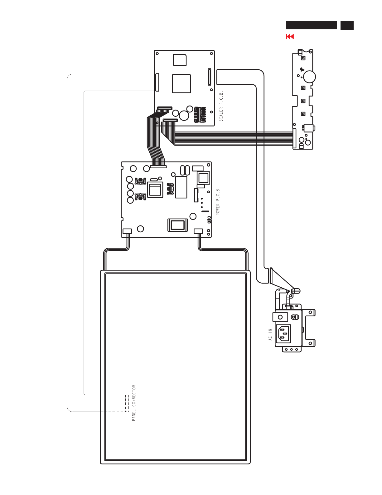
Go to cover page
Wiring Diagram

HP L1502
12
Go to cover page
Flat Panel Adjust
Optimizing Performance
Installing FPadjust Program
For best performance, ensure that your display settings are set at 1024x768@60Hz (for
14"/15") or 1280x1024, 60Hz (for 17"/18").
Note: You can check the current display settings by pressing the 'OK' button once. Go into the
Product Information.
The current display mode is shown on the item called RESOLUTION.
You can also install the Flat Panel Adjust (FP Adjust) program, a program for getting the best
performance out of your monitor. This included on this CD. Step-by-step instructions are
provided to guide you through the installtion process. Click on the link to know more about this
program.
The FP Adjust program generates alignment patterns which will help you adjust monitor
settings such as CONTRAST, BRIGHTNESS, HORIZONTAL & VERTICAL POSITION, PHASE
and CLOCK.
System requirements:
PC running Windows 95, Windows 98, Windows 2000, Winodws Me, Windows XP or later
To install FPadjust Program:
Click on the link or icon to install FPadjustment Program.
or
Click-and-hold your mouse over the icon. (Win95/98/2000/Me/XP users right-click)
Download FP_setup04.exe
From the menu that appears, choose 'Save Link As...', 'Save Target As...' or 'Download Link to
Disk'.
Choose where you would like to save the file; click 'Save' (if prompted to save as either 'text'
or 'source', choose 'source'). Exit your browser and install the FPadjust Program. Read the
"FP_Readme04.txt" file before installing.

170C4/N4
13
Go to cover page
Definition of Pixel Defects
LCD Monitor Quality and Pixel Policy
The TFT monitor uses high-precision technology, manufactured according to HP
standards, to guarantee trouble-free performance. Nevertheless, the display
may have cosmetic imperfections that appear as small bright or dark spots. This
is common to all LCD displays used in products supplied by all vendors and is not
specific to the HP LCD. These imperfections are caused by one or more
defective pixels or sub-pixels.
1. A pixel consists of one red, one green, and one blue sub-pixel.
2. A defective whole pixel is always turned on (a bright spot on a dark
background), or it is always off (a dark spot on a bright background). The first
is the more visible of the two.3. Adefective sub-pixel (dot defect) is less
3. visible than a defective whole pixel
and is small and only visible on a specific background.
The HP display does not have more than:
4. 3 bright dots.
5. 5 dark dots.
6. 5 total bright and dark dots.
7. No more than two adjacent (less than 2.5 mm edge-to-edge)
defective pixels.
To locate defective pixels, the monitor should be viewed under normal operating
conditions, in normal operating mode at a supported resolution and refresh rate,
from a distance of approximately 50 cm (16 in.).
HP expects that, over time, the industry will continue to improve its ability to
produce LCDs with fewer cosmetic imperfections And HP will adjust guidelines
as improvements are made.
HP L1502
14
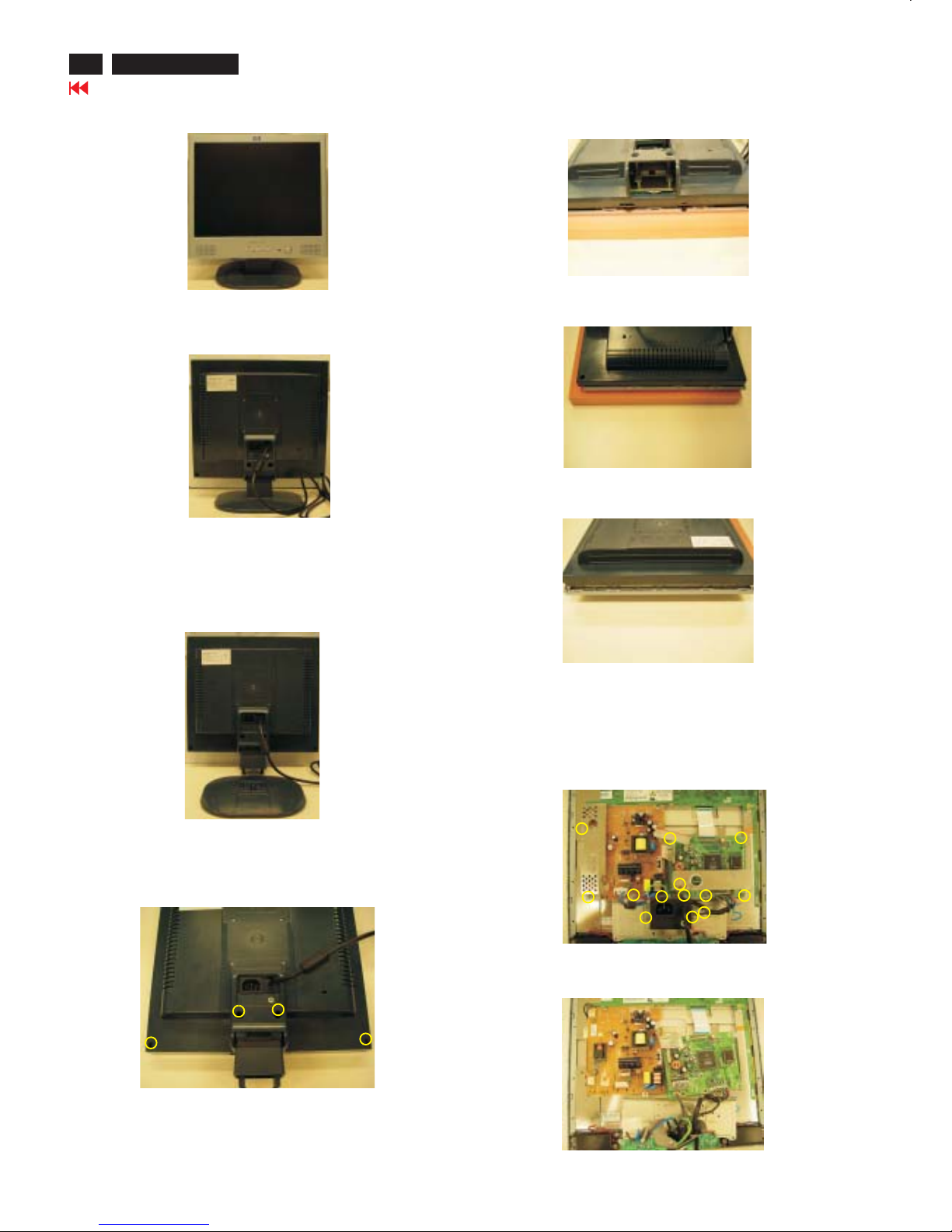
Go to cover page
Mechanical Instructions
Front view-HP L1523
Fig. 1
Fig. 2
Fig. 3
Step 1. Remove the Base as Fig .3
Remove the four screws of Fig. 4.Back cover as
Step 2.Remove the
Use the thin "I" type screw driver to open the clicks as Fig.5~7.
back cover
Fig. 4
Back view
Fig.5
Fig.6
Step 3. Remove the 13 screws
And Disconnect the 4 cables as Fig.8
Base =====>
Four screws
=====>
=====>
=============>
============>
Botton view
Right and Left view
Fig.7
Top view
=====>
=====>
=====>
=====>
=====>
=====>
=====>
=====>
===>
=====>
=====>
Fig.8
=====>
4 Cables
===>
===========>
Fig.9
Step 4. Disconnect the 2 cables as Fig.9
2 cables===>
========>
HP L1502
15
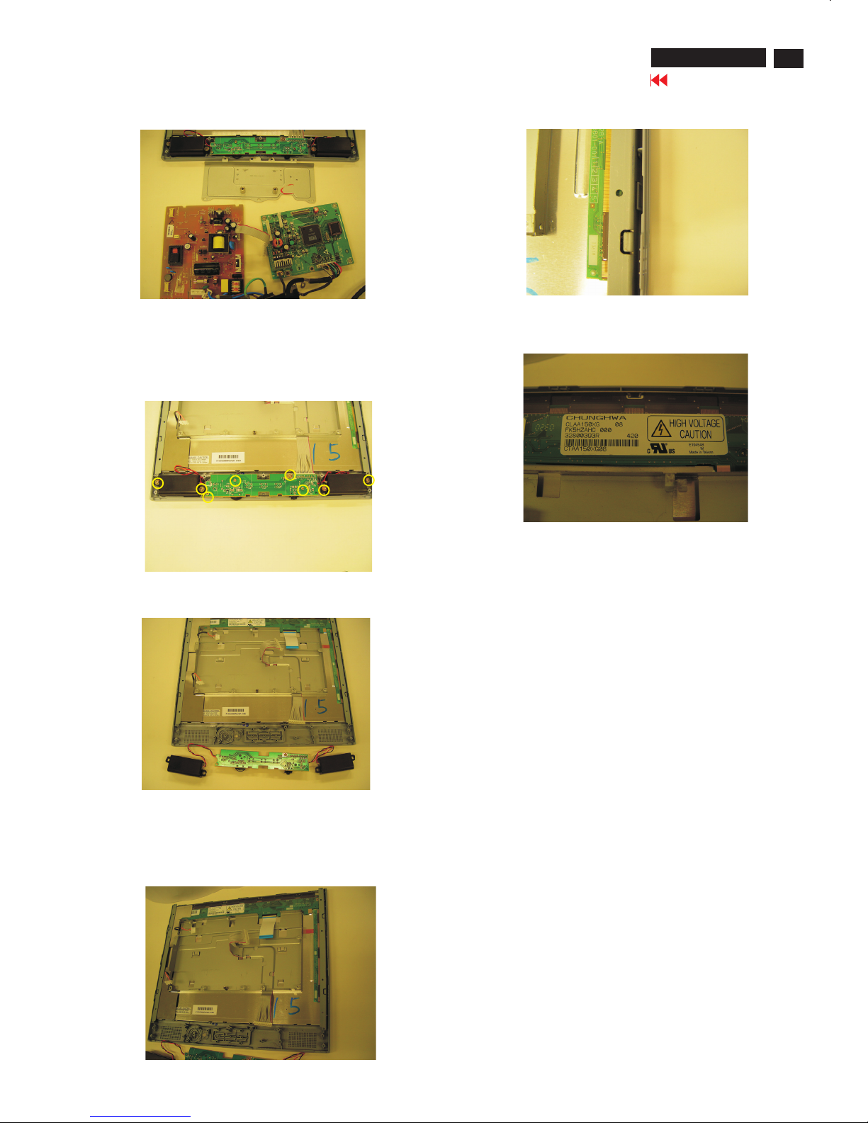
Go to cover page
Mechanical Instructions
Remove the Scaler and Power board as Fig. 10.
Fig. 11
Fig. 12
Step 6. Remove the Front Bezel
Use the thin "I" type screw driver to open the clicks
as Fig.13 &14.
Fig. 10
Fig. 13
Fig. 15
***************************************************************************
In warranty, it is not allowed to disassembly the LCD panel, even the
backlight unit defect.
Out of warranty, the replacment of backlight unit is a correct way
when the defect is cused by backlight (CCFL,Lamp).
***************************************************************************
Step 5. Remove the control board
Remove the seven screws and cable as Fig. 11 & 12.
Scaler board
Power board
Cable
======>
Fig. 14
1050 9322 196 43682 TFT-LCD LS150X05 (LGPH)
1050 9322 195 10682 TFT-LCD CLAA150XG08 (CPT0)
======>
======>
======>
======>
16
HP L1502
Go to cover page
Safety Test Requirements
All units that are returned for service or repair must pass the
original manufactures safety tests. Safety testing requires both
and testing.Hipot Ground Continuity
HI-POT TEST INSTRUCTION
1. Application requirements
2. Test method
1.1 All mains operated products must pass the Hi-Pot test as
described in this instruction.
1.2 This test must be performed again after the covers have
been refitted following the repair, inspection or modification
of the product.
2.1 Connecting conditions
2.1.1 The test specified must be applied between the parallel-
blade plug of the mainscord and all accessible metal
parts of the product.
2.1.2 Before carrying out the test, reliable conductive
connections must be ensured and thereafter be
maintained throughout the test period.
2.1.3 The mains switch(es) must be in the "ON" position.
2.2 Test Requirements
All products should be HiPot and Ground Continuity tested as
follows:
Test 2820VDC 1700VDC Test current:
voltage (2000VAC) (1200VAC) 25A,AC
Test time:
Test time 3 seconds 1 second 3 seconds(min.)
(min.) Resistance
required:
Trip set at 100 uA 5 mA <=0.09+R ohm,
current for Max. R is the
(Tester) limitation; set resistance of
at 0.1 uA for the mains cord.
Min. limitation
Ramp set at 2
time seconds
Condition HiPot Test for HiPot Test for Ground Continuity
products where products where Test requirement
the mains input the mains input is
range is Full 110V AC(USA
range(or 220V type)
AC)
2.2.1 The test with AC voltage is only for production purpose,
2.2.2 The minimum test duration for Quality Control Inspector
must be 1 minute. No breakdown during the test.
2.2.3 The test voltage must be maintained within the specified
voltage + 5%.
2.2.4 The grounding blade or pin of mains plug must be
conducted with accessible metal parts.
Service center shall use DC voltage.
3. Equipments and Connection
4. Recording
3.1. Equipments
For example :
- ChenHwa 9032 PROGRAMMABLE AUTO SAFETY
TESTER
- ChenHwa 510B Digital Grounding Continuity Tester
- ChenHwa 901 (AC Hi-pot test), 902 (AC, DC Hi-pot test)
Withstanding Tester
3.2. Connection
Hipot and Ground Continuity testing records have to be kept for
a period of 10 years.
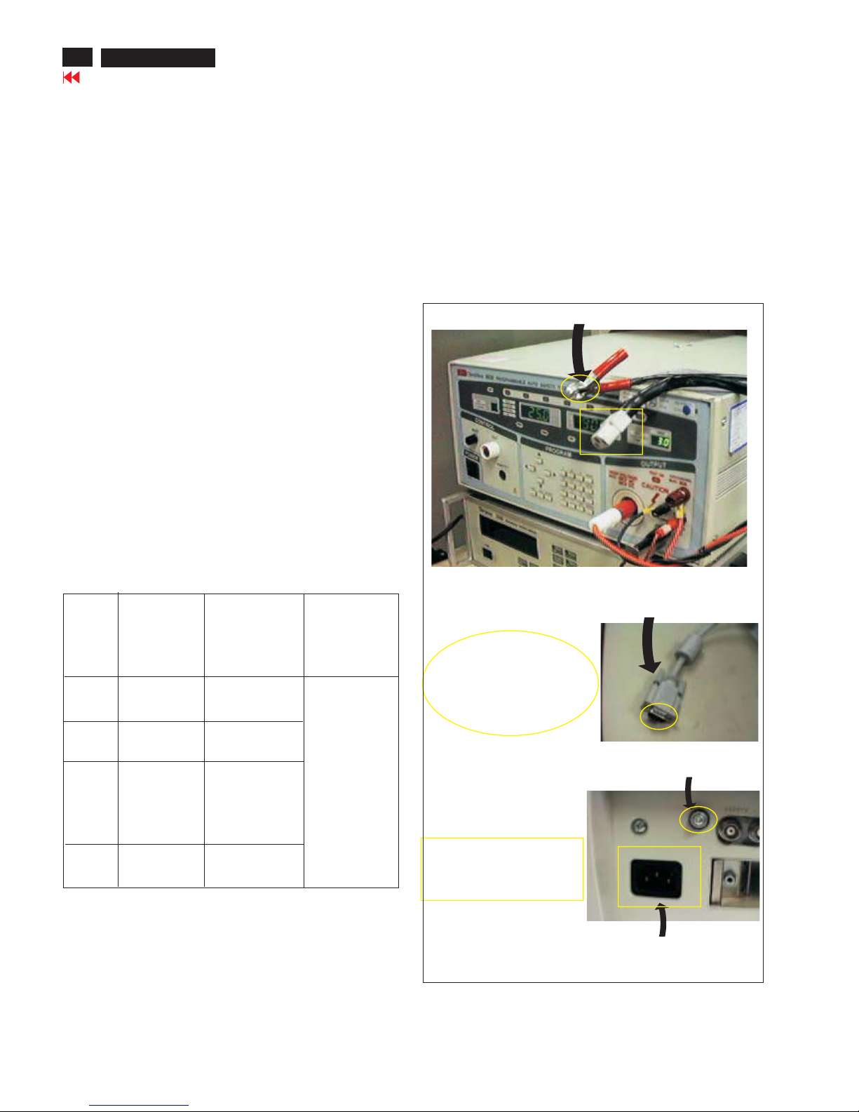
* Turn on the power switch of monitor before Hipot and
Ground Continuity testing.
Connect the "video cable"
or "grounding screw"
to the CLIP on your tester.
Video cable
(Rear view of monitor)
Connect the power cord
to the monitor.
Grounding screw
Power outlet
(ChenHwa 9032 tester)
Clip
Clip
HP L1502
17
Electrical Instructions
Go to cover page
1.
1.1 During the test and measuring, supply a distortion free AC mains
voltage To the apparatus via an isolated transformer with low
internal resistance.
1.2 All measurements mentioned hereafter are carried out at a normal
mains voltage (90 - 132 VAC for USA version, 195 -264 VAC for
EUROPEAN version, or 90 - 264 VAC for the model with full range
power supply, unless otherwise stated.)
1.3 All voltages are to be measured or applied with respect to ground,
unless otherwise stated.
Note: don't use heat-sink as ground.
1.4 The test has to be done on a complete set including LCD panel
after 30 minutes warm-up at least in a room with temperature of 25
+/- 5 degree C.
1.5 All values mentioned in this test instruction are only applicable of a
well aligned apparatus, with correct signal.
1.6 The letters symbols (B) and (S) placed behind the test instruction
denotes (B): carried out 100% inspection at assembly line
(S): carried out test by sampling
1.7 The white balance (color temperature) has to be tested in subdued
lighted room.
1.8 Repetitive power on/off cycle are allowed except it should be
avoided within 6 secretary.
2.1 Signal type
Video: 0.7 Vpp linear, positive polarity
Sync. : TTL level, separate, positive or negative polarity
Reference generator: CHROMA 2200 or 2250
Allowed signal modes list: Table A
General points
Input signal2.
TABLE A
FACTORY PRESET DISPLAY MODES
Pixel
Format
Horz
Freq
(KHz)
Horz
Polarity
Vert
Freq
(Hz)
Vert
Polarity
Pixel
Clk
(MHz)
1 640 x 480 31.469 - 59.940 - 25.175 VGA
2 640 x 480 37.861 - 72.809 - 31.500 VESA
3 640 x 480 37.500 - 75.000 - 31.500 VESA
4 720 x 400 31.469 - 70.087 + 28.322 VGA
5 800 x 600 37.879 + 60.317 + 40.000 VESA
6 800 x 600 48.077 + 72.188 + 50.000 VESA
7 800 x 600 46.875 + 75.000 + 49.500 VESA
8 832 x 624 49.726 +/- 74.551 +/- 57.284 MAC
9 1024 x
768
48.363 - 60.004 - 65.000 VESA
10 1024 x
768
56.476 - 70.069 - 75.000 VESA
11 1024 x
768
60.023 + 75.029 + 78.750 VESA
3. Display Adjustment (B)
Access to factory mode. Check “CPU version”, if it is not right
version, then ISP new one (7301). After pre-check, aging 1 hour at
Least. Programming Analog DDC Data into Monitor.
3.1 Panel flicker adjustment (B)
Apply a 48kHz/60Hz signal with green pixel on/off at 128/256-level
pattern for LG panel. Set brightness control at 100%, and contrast
control at 50%, adjust GPIO1 of 7443 GM2116AA which is on
scaler board to make panel's flicker minimum.
3.2 Auto color adjustment
Apply a 48.36kHz/60Hz signal with white pattern.
Set brightness at 100% and contrast at 80%.
Using auto color, let scaler calibrate offset1,offset2 and gain itself.
** Check the 64-gray level is distinguishable.
3.3 Color temperature adjustment
Apply a 48.36kHz / 60Hz signal with white pattern.
Set brightness control at 100% and contrast control at 50%.
Adjust the R.G.B gain to reach special color temperature on
center of screen. Keep one color fixed gain to maximum at least.
The 1931 CIE chromaticity (x, y) coordinates shall be:
Use Minolta CA-110 for color coordinates and luminance check.
3.4 NVRAM(24C16) Default Values
Sub_Bri: 165 255/LG 230/CPT 225/QDI
Sub_Con: 100 127 154
VCOM: 152
3.5 Factory Reset
After finishing all the adjustment, select “Factory Reset” function
to recall:
Do an automatic Auto-Adjustment
Set Brightness = 100
Set Contrast = 50
Set Color = 6500K-sRGB
Set Custom Color (R.G.B) = 100
3.6 Main Menu Factory Default Values
The OSD shall have the following factory default values:
Language = English
OSD Cotrol:
Horizontal OSD position = 50
Vertical OSD position = 50
OSD timeout = 30s
Management:
Power Saver = ON
Power On Recall = ON
Mode display = OFF
Sleep Timer = OFF
Menu = BASIC
9300°K 6500°K-sRGB
x (center) 0.283 ± 0.005 0.313 ± 0.005
y (center) 0.297 ± 0.005 0.329 ± 0.005
18
HP L1502
Display Adjustment
Display Adjustment:
Press and button simultaneously while power ON.
Adjust OSD menu to lower position of screen (i.g. adjust OSD HPosition and OSD V-Position to 0 at OSD setup sub-menu. Then
press or button to move the cursor to
item ( see yellow circle on table 1). Press button to access
to factory mode (see table2.). Check the code of CPU version if it
is not right version, then ISP new one (7301). After pre-check,
aging 1 hour at least. Programming Analog DDC data into
Monitor. Check # serial number to meet bar code label.
+
Down Up Factory Entrance
Menu
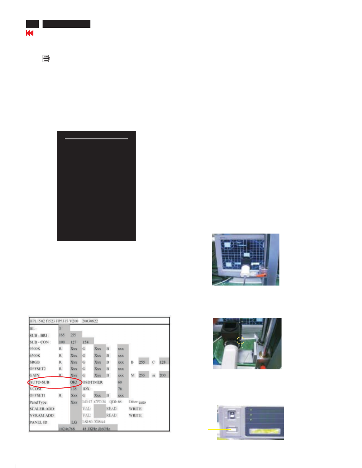
Table 2. The content of Factory setting.see table 2.
Cursor can move on gray color area
1. Auto color adjustment:
Apply a 48.36kHz/60Hz signal with white pattern. Set brightness
at 100% and contrast at 50%. Move the cursor by pressing or
button to ( see red circle on table 2 ), press OK
button to do auto color, scaler would calibrate offset1,offset2 and
gain itself then display OK. Check the 64-gray level is
distinguishable.
Up
Down AutoColor
Table 1.
2. Color temperature adjustment:
Apply a 48.36kHz / 60Hz signal with white pattern.Set brightness
control at 100% and contrast control at 50%. Adjust the R.G.B
gain to reach special color temperature on center of screen.
Keep one color fixed gain to maximum at least.
2 .1 Aim the probe CA-A30 at the center of screen as Fig. 1
2 .2 Remove the lens protective cover of probe CA-A30.
2 .3 Set Measuring/viewing selector to Measuring position for reset
analyzer. (Zero calibration) as Fig. 2
2 .4 Turn on the colour analyzer (CA-110).
2 .5 Press 0-CAL button to start reset analyzer. See Fig.3
Table 2.
Measurement/viewing selectorMeasurement/viewing selector
cover (black)cover (black)
Fig. 1
Fig. 2
Fig. 3
0-CAL
Go to cover page
Main manu
Brightness
Contrast
Image control
Color
Language
Management
OSD control
Factory reset
Exit F
<-------------Factory mode indicator
<------Version of code indicator
19
HP L1502
Display Adjustment
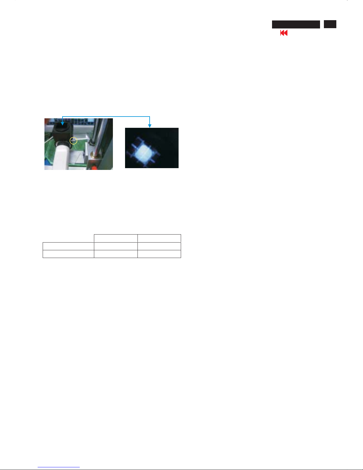
2.6 Switch light probe to Viewing position.
2.7 Move the Lens barrel forward or backward to get clear image as
shown in Fig. 4
2.8 Switch light probe to Measuring position. It should be able to
indicate colour value on the CA-110.
Measurement/viewing selectorMeasurement/viewing selector
Fig. 4
Clear image
2.9 Press buttons to selectRGBof9300 and 6500.
Increase / decrease value by press or buttons until the
1931 CIE chromaticity ( x,y)asbelow.
Menu
Up Down
Alignment hits:
1. R for x value , G for y value, B for Y value on the colour analyzer.
2. Must to select 9300 in user mode, then 9300 is available in factory
Mode.
3. Must to select 6500 in user mode, then 6500 is available in factory
Mode.
3. NVRAM(24C16) Default Values:
Sub_Bri: 165 255/LG 230/CPT 225/QDI
Sub_Con: 100 127 154
VCOM: 152
4. Factory Reset:
After finishing all the adjustment, select “Factory Reset” function
to recall:
Do an automatic Auto-Adjustment
Set Brightness = 100
Set Contrast = 50
Set Color = 6500K-sRGB
Set Custom Color (R.G.B) = 100
To leave factory mode by restart the monitor.
9300°K 6500°K
x (center) 0.283 ± 0.020 0.313 ± 0.020
y (center) 0.297 ± 0.020 0.329 ± 0.020
5. EEPROM Presetting:
6.Main Menu Factory Default Values
After finishing all the adjustment,Set:
Brightness control to 100%
Contrast control to 50%
OSD position at middle of screen.
Color Adjust to 6500K color.
When adjustment is finished,monitor should be set to 6500K.
The OSD shall have the following factory default values:
Language = English
OSD Cotrol:
Horizontal OSD position = 50
Vertical OSD position = 50
OSD timeout = 30s
Management:
Power Saver = ON
Power On Recall = ON
Mode display = OFF
Sleep Timer = OFF
Go to cover page
PIN MNEMONIC SIGNAL
1 RV Red Video
2 GV Green Video/Sync on Green
3 BV Blue Video
4 NC None
5 GND Ground (DDC Return) or Cable detect
6RGRedGND
7GGGreenGND
8BGBlueGND
9+5V+5V
10 SG Sync GND or Cable detect
11 NC None
12 SDA DDC Data
13 HS Horizontal Sync
14 VS Vertical Sync
15 SCL DDC Clock
Go to cover page
X
20
HP L1502
DDC Instructions
General
Pin assignment
A. 15-pin D-Sub Connector
DDC Data Re-programming
Analog DDC IC, & EEPROM
Additional information
In case the DDC data memory IC or main EEPROM which storage all
factory settings were replaced due to a defect, the serial numbers have
to be re-programmed" ".
It is advised to re-soldered DDC IC and main EEPROM from the old
board onto the new board if circuit board have been replaced, in this
case the DDC data does not need to be re-programmed.
Additional information about DDC (Display Data Channel) may be
obtained from Video Electronics Standards Association (VESA).
Extended Display Identification Data(EDID) information may be also
obtained from VESA.
1. An i486 (or above) personal computer or compatible.
2. Microsoft operation system Windows 95/98 .
Y o Install the EDID_PORT_Tool under Win2000/XP . As
Fig. 1 .
A. Cody the "UserPort.sys" to C:\WINNT\system32\drivers(win2000)
C:\WINDOWS\system32\drivers(winXP)
B. Running " io.exe" everytime, Before you start to programming
edid data .
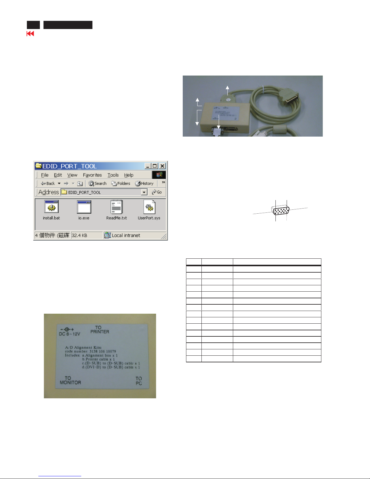
4. A/D Alignment kits (3138 106 10079):
inclusion : a. Alignment box x1 (as Fig. 2)
b. Printer cable x1
c. (D-Sub) to (D-Sub) cable x1
Note: The EDID45.EXE is a windows-based program, which cannot
be run in MS-DOS.
System and equipment requirements
ou have t
3. EDID45.EXE program .
Note: The alignment box has already build-in a batteries socket for
using as power source. Pull out the socket by
remove four screws at the rear of box. Please do not forget that
remove batteries after programming. The energy of batteries can
only drive circuits for a short period of time.
batteries (5V)
Fig. 2Fig. 2
Fig. 1Fig. 1
1
5
6
10
11
15
To Monitor
D-sub cable
DC 5V
To Printer port
Power
indicator
Fig. 3Fig. 3
 Loading...