

Page 1
1
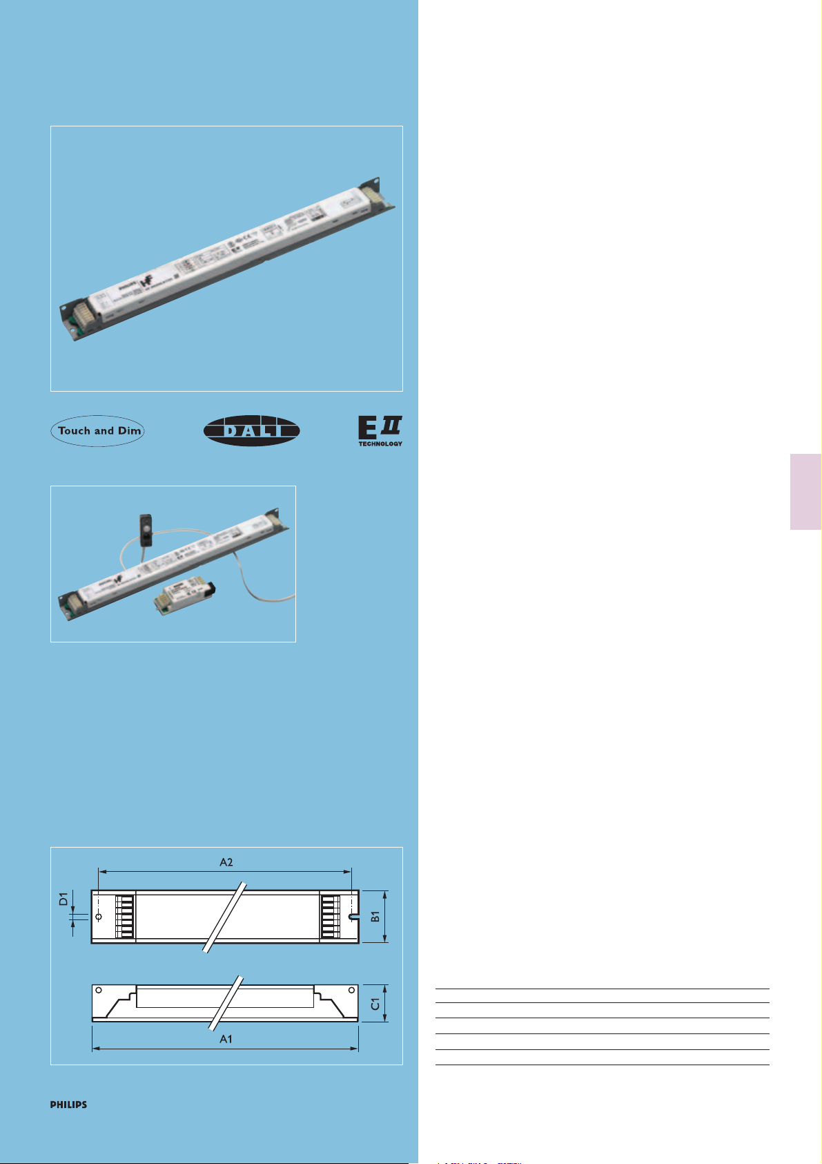
HF-REGULATORII Touch and DALI TL5
Dimensions in mm
A1 A2 B1 C1 D1
1 Lamp 360 350 30 21 4.2
2 Lamps 360 350 30 21 4.2
2x80W 425 415 30 21 4.2
3/4 Lamps 360 350 39 21 4.2
Dimensions in mm
Fluorescent electronic
(Additional to Chapter 3.12 catalogue 2005/2006)
Product description
Flat, lightweight high-frequency electronic regulating ballast, using
DALI (Digital Addressable Lighting Interface) or Touch and Dim push
button protocol, for TL5 fluorescent lamps.The HF-REGULATORII
ballasts incorporate the new Philips EII technology offering full digital
input (mains) and output (lamp) management.
Features and benefits
• The lamp power can be regulated from 100% to 1%.
• Flat ballast design, 21 mm high.
• Up to 75% reduction in energy consumption can be achieved by
using automatic lighting control systems (e.g. Philips ActiLume
luminaire-based system solutions).
• Quick programmed start: 0.5 sec, flicker-free warm star t,
preheating the lamp electrodes.This enables the lamps to be
switched on and off without reducing useful life. Ideal for areas
with a high switching frequency.
• Digital control input according to the industry standard DALI
(Digital Addressable Lighting Interface) combined with the Touch
and Dim push button protocol.
• Low energy consumption in standby 0.35W due to the new EII
technology.
• Increased lamp wire flexibility thanks to the Parasitic Capacitance
Compensation (longer lamp wiring possible up to 2 meter).
• Smart power: constant light, independent of mains voltage
fluctuations.
• Unit is protected against excessive mains voltages incorrect
connections and incorrect lamp use.
• Striation-free operation, no stroboscopic effects.
• Lamp starts at 1% (DALI 1...100% in 100 ms).
• Automatic stop circuit is activated within five seconds in case of
lamp failure (safety stop). Once the lamp has been replaced, the
ballast resets automatically.
• Equipped with connectors suitable for automatic wiring machines.
The Philips HF-REGULATORII electronic ballasts are equipped with
EII-dim technology. This is a dedicated integrated circuit that ensures
independent control of each electrode and, in doing so, takes care
that:
a. lamp life is unaffected by dimming position
b. lamp burning is stable in every dimming position; and
c. energy savings, when dimming are maximised.
Applications
Typical areas of application include:
• DALI installations with daylight linking and/or movement
detection (for energy savings)
• DALI installations with remote control systems (combining energy
savings with comfort)
• Installations with emergency back-up, according to IEC 60598-222/VDE 0108.
• Office applications were a simple and easy to install dimming
system or personal light level adjustment is required.
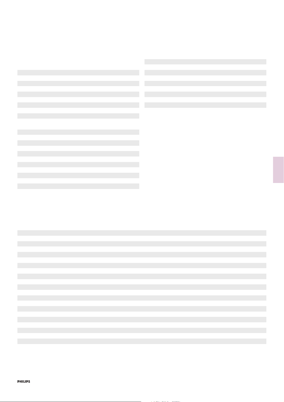
HF-REGULATORII (Touch and DALI)
HF-REGULATORII is used in ActiLume systems for
automatic light control
Page 2

2
HF-REGULATORII Touch and DALI TL5
Examples
• Office buildings: insurance companies, banks, government ministries
- Cellular or open plan offices
- Conference rooms, lecture theatres, corridors
• Schools
• Hospitals
• Department stores, shops, supermarkets
• Hotels, restaurants and bars
• Cinemas, museums.
Philips quality
This applies optimum quality with respect to:
• System supplier
As manufacturer of lamps, electronic control gear and lighting
control equipment, Philips ensures that, from the earliest
development stage, optimum performance is maintained.
• International standards
Philips HF electronic regulating ballasts comply with all relevant
international rules and regulations.
Compliances and approvals
• RFI<30 MHz: EN 55015
• RFI>30 MHz: EN 55022 limit B
• Harmonics: EN 61000-3-2
• Immunity: EN 61547
• Safety: EN 61347-2-3
• Performance: EN 60929
• Vibration & bump tests: EN 60068-2-6-FC
EN 60068-2-29-Eb
• Quality standard: ISO 9001
• Environmental standard: ISO 14001
• Approval marks: ENEC
EMV-VDE
• Temp. declared thermally protected: EN 61347-1
• CE marking
Technical data for installation
Mains operation
Rated mains voltage 220-240 V
With tolerances for safety: +/- 10% 198-264 V
Tolerances for performance +6%-8% 202-254 V
Mains frequency 50/60 Hz
Smart power: with AC mains voltage fluctuations, 202-254 V
luminous flux varies by ± 2% max.
DC voltage operation (during emergency back-up)
Required battery voltage for guaranteed ignition 198V – 254 V
Required battery voltage for burning lamps 176V – 254 V
Nominal light output is obtained at a voltage of 220V – 240 V
110
Fluorescent electronic
(Additional to Chapter 3.12 catalogue 2005/2006)
Notes:
1. For continuous DC application, an external fuse should be used in
the luminaire.
2. Continuous low DC voltages (<198 V) can influence the lifetime of
the ballast.
3. For the HF-R TD 280 TL5/PL-L lamp EII power will be limited to
50% of the nominal lamp power when operating on DC.
Earth leakage current < 0.5 mA per ballast
Maximum number of ballasts which can be
connected to one Residual Current Detector
of 30 mA 30
Overvoltage protection 48 hrs at 320 V AC
2 hrs at 350 V AC
Automatic restart after lamp replacement
or voltage dip Yes
Mains current at 230V
Ballast Lamp type Qty of Input
Lamps current
A
HF-R TD 114-35 TL5 EII TL5 14 W HE 1 0.09
HF-R TD 214-35 TL5 EII TL5 14 W HE 2 0.15
HF-R TD 314 TL5 EII TL5 14 W HE 3 -
HF-R TD 414 TL5 EII TL5 14 W HE 4 -
HF-R TD 114-35 TL5 EII TL5 21 W HE 1 0.12
HF-R TD 214-35 TL5 EII TL5 21 W HE 2 0.23
HF-R TD 114-35 TL5 EII TL5 28 W HE 1 0.14
HF-R TD 214-35 TL5 EII TL5 28 W HE 2 0.27
HF-R TD 114-35 TL5 EII TL5 35 W HE 1 0.17
HF-R TD 214-35 TL5 EII TL5 35 W HE 2 0.34
HF-R TD 124 TL5 EII TL5 24 W HO 1 -
HF-R TD 224 TL5 EII TL5 24 W HO 2 -
HF-R TD 324 TL5 EII TL5 24 W HO 3 -
HF-R TD 424 TL5 EII TL5 24 W HO 4 -
HF-R TD 139 TL5 EII TL5 39 W HO 1 -
HF-R TD 239 TL5 EII TL5 39 W HO 2 -
HF-R TD 149 TL5 EII TL5 49 W HO 1 0.24
HF-R TD 249 TL5 EII TL5 49 W HO 2 0.45
HF-R TD 154 TL5 EII TL5 54 W HO 1 0.26
HF-R TD 254 TL5 EII TL5 54 W HO 2 0.52
HF-R TD 180 TL5/PL-L EII TL5 80 W HO 1 0.38
HF-R TD 280 TL5/PL-L EII TL5 80 W HO 2 0.75
Page 3
3
HF-REGULATORII Touch and DALI TL5
Technical data (all typical values at Vmains =230 V)
Lamps Qty of Ballast System Lamp Ballast Efficacy Lumen* CELMA
Lamps Power* Power* Loss* at 35 ºC** Nom.*
W W W lm/W lm EEI
TL5 HE 14W 1 HF-R TD 114-35 TL5 EII 18 14 4 96 1200 A1
TL5 HE 14W 2 HF-R TD 214-35 TL5 EII 34 28 6 96 2400 A1
TL5 HE 14W 3 HF-R TD 314 TL5 EII - - - - 3600 A1
TL5 HE 14W 4 HF-R TD 414 TL5 EII - - - - 4800 A1
TL5 HE 21W 1 HF-R TD 114-35 TL5 EII 25 22 3 100 1900 A1
TL5 HE 21W 2 HF-R TD 214-35 TL5 EII 50 44 6 100 3800 A1
TL5 HE 28W 1 HF-R TD 114-35 TL5 EII 32 28 4 104 2600 A1
TL5 HE 28W 2 HF-R TD 214-35 TL5 EII 61 56 6 104 5200 A1
TL5 HE 35W 1 HF-R TD 114-35 TL5 EII 38 35 4 104 3300 A1
TL5 HE 35W 2 HF-R TD 214-35 TL5 EII 77 70 7 104 6600 A1
TL5 HO 24W 1 HF-R TD 124 TL5 EII - - - - 2000 A1
TL5 HO 24W 2 HF-R TD 224 TL5 EII - - - - 4000 A1
TL5 HO 24W 3 HF-R TD 324 TL5 EII - - - - 6000 A1
TL5 HO 24W 4 HF-R TD 424 TL5 EII - - - - 8000 A1
TL5 HO 39W 1 HF-R TD 139 TL5 EII - - - - 3500 A1
TL5 HO 39W 2 HF-R TD 239 TL5 EII - - - - 7000 A1
TL5 HO 49W 1 HF-R TD 149 TL5 EII 54 49 5 99 4300 A1
TL5 HO 49W 2 HF-R TD 249 TL5 EII 106 98 8 99 8600 A1
TL5 HO 54W 1 HF-R TD 154 TL5 EII 60 54 6 93 4450 A1
TL5 HO 54W 2 HF-R TD 254 TL5 EII 119 108 11 93 8900 A1
TL5 HO 80W 1 HF-R TD 180 TL5/PL-L EII 87 80 7 88 6150 A1
TL5 HO 80W 2 HF-R TD 280 TL5/PL-L EII 174 162 12 88 12300 A1
* Typical values for /830 measured at 100% power and 25 ºC lamp ambient temperature
** Typical values at 35 ºC (light top for MASTER TL5 Super 80 lamps)
Inrush current
Ballast Qty Max. quantity of ballasts Inrush current
of Lamps per Miniature Circuit 1/2 value time at
Breaker typical mains
Type B16 A impedance
HF-R TD 114-35 TL5 EII 1x14 28 27A/300 µS
HF-R TD 214-35 TL5 EII 2x14 12 45A/400 µS
HF-R TD 314 TL5 EII 3x14 - -
HF-R TD 414 TL5 EII 4x14 - -
HF-R TD 114-35 TL5 EII 1x21 28 27A/300 µS
HF-R TD 214-35 TL5 EII 2x21 12 45A/400 µS
HF-R TD 114-35 TL5 EII 1x28 28 27A/300 µS
HF-R TD 214-35 TL5 EII 2x28 12 45A/400 µS
HF-R TD 114-35 TL5 EII 1x35 28 27A/300 µS
HF-R TD 214-35 TL5 EII 2x35 12 45A/400 µS
HF-R TD 124 TL5 EII 1 - -
HF-R TD 224 TL5 EII 2 - -
HF-R TD 324 TL5 EII 3 - -
HF-R TD 424 TL5 EII 4 - -
HF-R TD 139 TL5 EII 1 - -
HF-R TD 239 TL5 EII 2 - -
HF-R TD 149 TL5 EII 1 28 19A/220 µS
HF-R TD 249 TL5 EII 2 12 32A/300 µS
HF-R TD 154 TL5 EII 1 28 24A/250 µS
HF-R TD 254 TL5 EII 2 12 45A/400 µS
HF-R TD 180 TL5/PL-L EII 1 12 45A/400 µS
HF-R TD 280 TL5/PL-L EII 2 9 35A/350 µS
Conversion table for max. quantities of ballasts on other
types of Miniature Circuit Breakers
MCB Type Relative quantity of ballasts
B 16A 100%(see table on the left)
B 10A 63%
C 16A 170%
C 10A 104%
L, I 16A 108%
L, I 10A 65%
G, U, II 16A 212%
G, U, II 10A 127%
K, III 16A 254%
K, III 10A 154%
Insulation resistance test 500 V DC from Line/Neutral to Ear th
(not between Line and Neutral)
Note: Ensure that the Neutral is
reconnected again after the above
mentioned test is carried out and
before the installation is put into
operation.
TL5 lamp wiring 500 V rated components and wiring
are required with HF-REGULATORII
TL5.
Ignition time Typical 0.5 sec. quick warm start.
Fluorescent electronic
(Additional to Chapter 3.12 catalogue 2005/2006)
Page 4

4
HF-REGULATORII Touch and DALI TL5
Lamp Qty of Ballast Power Max cable Cap
1)
Tc max Operating
Lamps Factor Lp-Lp/Lp-Lgnd Frequency
PF ºC kHz
TL5 HE 14W 1 HF-R TD 114-35 TL5 EII 0.95 100/75 75 42..110
TL5 HE 14W 2 HF-R TD 214-35 TL5 EII 0.95 100/75 75 42..110
TL5 HE 14W 3 HF-R TD 314 TL5 EII - - - -
TL5 HE 14W 4 HF-R TD 414 TL5 EII - - - -
TL5 HE 21W 1 HF-R TD 114-35 TL5 EII 0.96 100/75 75 42..110
TL5 HE 21W 2 HF-R TD 214-35 TL5 EII 0.97 100/75 75 42..110
TL5 HE 28W 1 HF-R TD 114-35 TL5 EII 0.97 100/75 75 42..110
TL5 HE 28W 2 HF-R TD 214-35 TL5 EII 0.98 100/75 75 42..110
TL5 HE 35W 1 HF-R TD 114-35 TL5 EII 0.99 100/75 75 42..110
TL5 HE 35W 2 HF-R TD 214-35 TL5 EII 0.99 100/75 75 42..110
TL5 HO 24W 1 HF-R TD 124 TL5 EII - - - -
TL5 HO 24W 2 HF-R TD 224 TL5 EII - - - -
TL5 HO 24W 3 HF-R TD 324 TL5 EII - - - -
TL5 HO 24W 4 HF-R TD 424 TL5 EII - - - -
TL5 HO 39W 1 HF-R TD 139 TL5 EII - - - -
TL5 HO 39W 2 HF-R TD 239 TL5 EII - - - -
TL5 HO 49W 1 HF-R TD 149 TL5 EII 0.98 100/150 75 42..110
TL5 HO 49W 2 HF-R TD 249 TL5 EII 0.99 50/75 75 42..110
TL5 HO 54W 1 HF-R TD 154 TL5 EII 0.98 100/150 75 42..110
TL5 HO 54W 2 HF-R TD 254 TL5 EII 0.99 50/75 75 42..110
TL5 HO 80W 1 HF-R TD 180 TL5/PL-L EII 0.99 100/150 75 42..110
TL5 HO 80W 2 HF-R TD 280 TL5/PL-L EII 0.99 100/150 75 42..110
1) Lp-Lp = between lamp wires Typical wire capacitance 50 pF/m (spacing between wires 0.5 mm)
Lp-Lgnd = between lamp wires and ground Typical wire capacitance 72 pF/m (spacing between wires 0.5 mm)
Protected against accidental mains voltage
connection Yes
Control input
Regulating level (lamp power) 1 to 100%
The control input complies with EN 60929
(Annex E) and is compatible with
Philips lighting control equipment
Standby power consumption < 350 mW
Control input insulation, basic insulation >_ 1500 V
Fluorescent electronic
(Additional to Chapter 3.12 catalogue 2005/2006)
Page 5

5
Digital steps according DALI
Relative light level
Option 1) DALI
Digital coded input signal according to “Digital Addressable Lighting
Interface” protocol, including 16 presets and 64 addresses possibility.
Option 2) Touch and Dim
A short push on the button represents the On/Off command.
Personal light levels can be stored in the internal memory by a firm
longer push on the push button.
Failure proof (non volatile) memory ensures that the ballast always
remembers your setting when next time switched on or in case of
power failure.
Maximum number of ballasts connected in one circuit 32 Pcs
(switched on by one or multiple switches)
Mains input signal Retractive push-to-make
switch
- Ignore status, <0.04 sec. To avoid reaction on
mains spikes!
- Shor t push, between 0.04 sec. and 0.5 sec. Switch On/Off
- Long push, between 0.5 sec. and 10 sec. Dim Up/Down
- Reset push, >10 sec. Set light to mid value
(35% output)
The dim function will toggle after each individual push. Except when
the value is lower than 10% it will always dim up, and when the light
output is higher than 70% it will always dim down to perform
according human perception.
Input power vs dimlevel HF-REGULATORII
(DALI/Touch and Dim)
Technical data for design and mounting in fixtures
Temperatures
Temperature range to ignite lamp
With ignition aid 0 °C to +50 °C
at a 70..100% dim input -20 ºC to +50 ºC
Storage temperature range -25 ºC to +80 ºC
Stable lamp operation assured > 15 °C*
Striation possible < 10 °C
* >20 °C for HF-R TD 280 TL5/PL-L EII
Max t case 75 °C
The lifetime of a ballast depends on the temperature of the ballast.
This means there is a relation between the Tc point on the ballast and
its lifetime.The HF-REGULATORII ballast for TL5 applications has a
specified lifetime of 50,000 hrs with a maximum of 10% failures
guaranteed at a measured Tcase of 75 °C.
For more information regarding this subject consult the Philips
Application guide for fluorescent lamp control gear.
Class II luminaires This application is not advisable; only with
extensive tests on luminaires can the
correct operation be verified
EMI precautions have to be taken
Outdoor Ballast IP=23
In outdoor the luminaire has to be
sufficiently IP rated
Permitted humidity is tested according to
EN 61347-1 par 11
Note that no moisture or condensation
may enter the ballast
Ignition aid For optimum ignition the TL5 lamps should
be mounted at a maximum distance of
6 mm from a metal plate
The metal plate should be electrically
connected to the ballast housing
Earthing Earthing of the HF ballast in a luminaire is
necessary for EMC (electromagnetic
compatibility)
Hum and noise level Inaudible
HF-REGULATORII Touch and DALI TL5Fluorescent electronic
(Additional to Chapter 3.12 catalogue 2005/2006)
Relation between lamp power and digital regulator
Mains power
Dimming level
Ballast power losses
Total lamp power
System power
Page 6

6
Release: rotate and pull
Remark: release all wires
one by one
IDC connection
ADS/Manual
connection
1 lamp
HF BALLAST
Wiring diagrams
HF-REGULATORII Touch and DALI TL5Fluorescent electronic
(Additional to Chapter 3.12 catalogue 2005/2006)
Wiring tips
Earth connection to be made via housing or mains connector.
Wiring inside fixture should be straight and as short as possible. Lamp
wires should not run parallel to mains or control wires to avoid EMC
problems. For optimal performance, note that:
• For one lamp ballasts wires 4 and 5 as short as possible, equal in
length and a minimum of 50 mm from mains or dim wires. Keep
lamp wires 6 and 7 equal in length.
• For two lamp ballasts wires 3, 4 and 5 as short as possible, equal in
length and a minimum of 50 mm from mains or dim wires. Keep
lamp wires 6 and 7, and 1 and 2 equal in length.
Notes
1. Data based on a mains supply with an impedance of 400 mΩ (equal
to 15 m cable of 2.5 mm
2
and another 20 m to the middle of the
power distribution), under worst case conditions. With an
impedance of 800 mΩ the number of ballasts can be increased by
10%.
2. Measurements will be verified in real installations, therefore data are
subject to change.
3. In some cases the maximum number of ballasts is not determined
by the MCB, but by the maximum electrical load of the lighting
installation.
4. Note that the maximum number of ballasts is based on the
assumption that these are all switched on at the same moment, i.e.
by a wall switch.
5. Measurements were carried out on single-pole MCB’s. For multi-
pole MCB’s it is recommended to reduce the number of ballasts
by 20%.
6. First digital regulating steps (DALI) are fixed at 1% light output
(dimming specification).
7. For optimum performance care has to be taken for symmetrical
wiring. Minimal 6 mm distance from lamp to earth plane.
8. In case of DC operation the HF-R TD 280 TL5/PL-L EII will have
maximum 40% light output
Connector type
Connection wiring is greatly simplified through use of WAGO 251
universal connector. Suitable for both automatic wiring (ALF and ADS)
and manual wiring.
Wire cross-section
IDC connection 0.5 mm - 1.0 mm
2
ADS manual connection 0.5 mm – 0.75 mm2*
*Stranded wire
Strip length 8.0 – 9.0 mm
2 lamps
HF BALLAST
Page 7

7
Ordering and packaging data
Ballast 1 Piece Bulk packaging
EAN code Weight Qty Dimensions Volume Weight EAN code EOC
lxwxh Gross
kg pcs cm m
3
kg
HF-R TD 114-35 TL5 EII 8711500 911582 0.26 12 40.8x20.8x7.6 0.0065 3.4 8711500 911599 911582 30
HF-R TD 214-35 TL5 EII 8711500 911629 0.29 12 40.8x20.8x7.6 0.0065 3.8 8711500 911636 911629 30
HF-R TD 149 TL5 EII 8711500 908889 0.26 12 40.8x20.8x7.6 0.0065 3.4 8711500 908896 908889 30
HF-R TD 249 TL5 EII 8711500 909596 0.31 12 40.8x20.8x7.6 0.0065 4.0 8711500 909602 909596 30
HF-R TD 154 TL5 EII 8711500 909619 0.27 12 40.8x20.8x7.6 0.0065 3.5 8711500 909626 909619 30
HF-R TD 254 TL5 EII 8711500 909633 0.33 12 40.8x20.8x7.6 0.0065 4.2 8711500 909640 909633 30
HF-R TD 180 TL5/PL-L EII 8711500 909657 0.29 12 40.8x20.8x7.6 0.0065 3.7 8711500 909664 909657 30
HF-R TD 280 TL5/PL-L EII 8711500 910677 0.42 12 47.6x20.6x7.6 0.0075 5.3 8711500 910691 910677 30
Ordering and packaging data
Ballast 1 Piece Bulk packaging
EAN code Weight Qty Dimensions Volume Weight EAN code EOC
lxwxh Gross
kg pcs cm m
3
kg
HF-R TD 124 TL5 EII
HF-R TD 224 TL5 EII
HF-R TD 139 TL5 EII
HF-R TD 239 TL5 EII
Ordering and packaging data
Ballast 1 Piece Bulk packaging
EAN code Weight Qty Dimensions Volume Weight EAN code EOC
lxwxh Gross
kg pcs cm m
3
kg
HF-R TD 314 TL5 EII
HF-R TD 414 TL5 EII
HF-R TD 324 TL5 EII
HF-R TD 424 TL5 EII
HF-REGULATORII Touch and DALI TL5Fluorescent electronic
(Additional to Chapter 3.12 catalogue 2005/2006)
Under development, Introduction Q4 2007
Under development, Introduction Q3 2007
Page 8

3222 635 56291
01/2007
Printed in the Netherlands
Data subject to change
 Loading...