

Philips HeartStart MRx M3535A, HeartStart MRxM3536A User manual
M3535A/M3536A
Instructor Guide
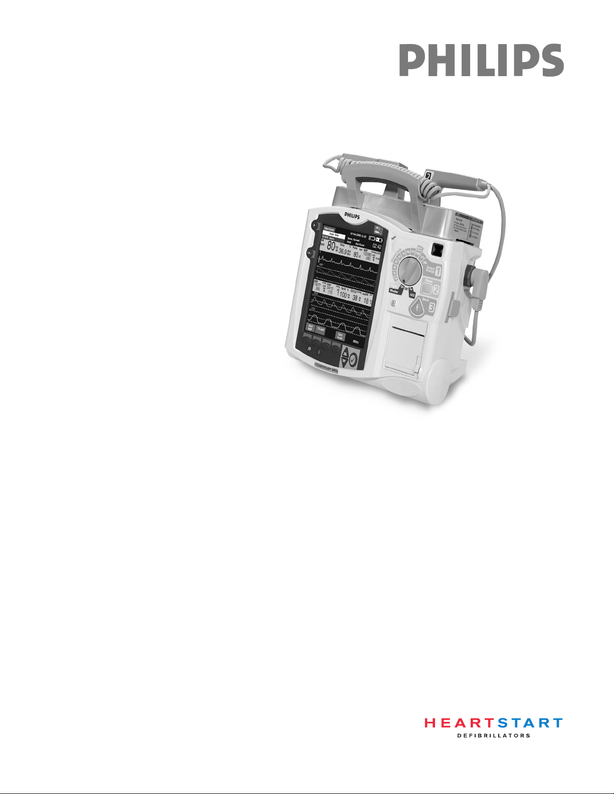
HeartStart MRx


Notice
About This Edition
Publication number 453564045041
Edition 1
Printed in the USA
To determine the product level version to which this
guide applies to, refer to the version level on the back
cover of this book or on the label of the User
Documentation CD-ROM that accompanied the device.
This information is subject to change without notice.
Philips shall not be liable for errors contained herein or
for incidental or consequential damages in connection
with the furnishing, performance, or use of this material.
Edition History
Edition Print Date
1 September, 2006
Copyright
Copyright © 2006
Koninklijke Philips Electronics N.V.
All rights are reserved. Permission is granted to copy and
distribute this document for your organization’s internal
educational use. Reproduction and/or distribution
outside your organization in whole or in part is
prohibited without the prior written consent of the
copyright holder.
SMART Biphasic is a registered
trademark of Philips.
®
Microstream
of Oridion Medical Ltd. Smart CapnoLine™ is a
trademark of Oridion Medical Ltd.
Q-CPR™ is a trademark of Laerdal Medical.
The HeartStart MRx contains an Ezurio PC Card with
Bluetooth
wordmark and logos are owned by the Bluetooth SIG,
Inc. and any use of such marks by Ezurio is under license.
Coverage Plus
trademarks of Steris Corp.
CidexPlus
Sterilization Products.
Other trademarks and trade names are those of their
respective owners.
and FilterLine® are registered trademarks
®
wireless technology. The Bluetooth
®
and Coverage Plus NPD® are registered
®
is a registered trademark of Advanced
Use of supplies or accessories other than those
recommended by Philips may compromise product
performance.
THIS PRODUCT IS NOT INTENDED FOR HOME
USE.
IN THE U.S., FEDERAL LAW RESTRICTS THIS
DEVICE TO SALE ON OR BY THE ORDER
OF A PHYSICIAN.
Medical Device Directive
The HeartStart MRx complies with the requirements of
the Medical Device Directive 93/42/EEC and carries the
mark accordingly.
0123
Manufacturer:
Philips Medical Systems
3000 Minuteman Road
Andover, MA 01810
Authorized EU-representative:
Philips Medizin Systeme Böblingen GmbH
Hewlett Packard Str. 2
71034 Böblingen
Germany
Canada EMC:ICES-001
China:
After Sales Service: Beijing MEHECO-PHILIPS Medical
Equipment Service Center.
After Sales Service Address: No. 208, 2nd District, Wang
Jing Li Ze Zhong Yuan, Chao Yang District, Beijing.
Postal code: 100102.
Telephone: 010-64392415.
Registration number: SFDA(I)20043211207.
Product Standard number: YZB/USA 52-21.
For the Declaration of Conformity Statement, please see
the Philips Medical web site at http://
incenter.medical.philips.com/PMSPublic. Scroll over the
Quality and Regulatory Tab located in the upper left
corner of the window. Click to select Regulatory by
Modality. Then click to select Defibrillators and select
the entry for Declaration of Conformity (DoC)
Warning
Radio frequency (RF) interference from nearby
transmitting devices may degrade the performance of the
HeartStart MRx. Electromagnetic compatibility with
surrounding devices should be assessed prior to using the
monitor/defibrillator.
.
i

This Instructor Guide contain the following conventions:
“Voice” represents voice prompt messages
Text represents messages that appear on the display
Text represents bolded directions to the instructor that appear in the guide and
options that appear on MRx menus
[Soft key] represents soft key labels that appear on the display above the
button to which they correspond.
ii

1Table of Contents
1 Introduction 1
2 Getting Acquainted 5
Lesson Introduction 5
Objectives 5
Time 5
Accessories Recommended 5
Lesson Presentation 6
Overview 6
Basic Orientation 6
Display View 10
Continued Use 15
Printing Waveforms 16
Return to Owner 16
Carrying Case and Accessory Pouch Assembly 18
Storing Accessories 20
Review 23
3 ECG and Arrhythmia Monitoring 25
Lesson Introduction 25
Objectives 25
Time 25
Accessories Recommended 25
Clinical Resources 25
Lesson Presentation 26
Overview 26
Monitor View 26
Preparation 27
Heart Rate and Arrhythmia Alarms 30
Displaying an Annotated ECG 35
Arrhythmia Learning/Relearning 36
Review 37
4 Semi-Automated
External Defibrillation 39
Lesson Introduction 39
Objectives 39
Time 39
Accessories Recommended 39
iii

Clinical Resources 39
Lesson Presentation 40
Overview 40
AED View 40
Preparation 41
AED Mode 42
Review 47
5 Manual Defibrillation
and Cardioversion 49
Lesson Introduction 49
Objectives 49
Time 49
Accessories Recommended 49
Clinical Resources 49
Lesson Presentation 50
Manual Mode 50
Code View 50
Manual Defibrillation Preparation 51
Manual Defibrillation 52
Synchronized Cardioversion 54
Synchronized Shock Delivery 55
Review 57
6 Q-CPR™ 59
Lesson Introduction 59
Objectives 59
Time 59
Accessories Recommended 59
Clinical Resources 59
Lesson Presentation 60
Overview 60
Q-CPR Preparation 61
Q-CPR in Manual Defib Mode 64
Q-CPR in AED Mode 67
Review 69
7 Noninvasive Pacing 71
Lesson Introduction 71
Objectives 71
Time 71
Accessories Recommended 71
Clinical Resources 71
Lesson Presentation 72
Pacer Mode 72
iv

Pacing View 73
Demand vs. Fixed Mode 74
Preparation 75
Demand Mode Pacing 76
Fixed Mode Pacing 78
Defibrillating During Pacing 79
Review 80
8 Pulse Oximetry Monitoring 81
Lesson Introduction 81
Objectives 81
Time 81
Accessories Recommended 81
Clinical Resources 81
Lesson Presentation 82
Overview 82
Selecting a Sensor 82
Applying the Sensor 83
Monitoring SpO
Pleth Wave 85
Setting SpO2 Alarms 86
Setting Pulse Rate Alarms 88
Disabling the SpO2 Monitoring Function 88
2
Review 90
84
9 Noninvasive Blood Pressure Monitoring 91
Lesson Introduction 91
Objectives 91
Time 91
Accessories Recommended 91
Clinical Resources 91
Lesson Presentation 92
Overview 92
Preparing to Measure NBP 93
Measuring NBP 94
Alarms 96
Review 98
10 Carbon Dioxide Monitoring 99
Lesson Introduction 99
Objectives 99
Time 99
Accessories Recommended 99
Clinical Resources 99
Lesson Presentation 100
Overview 100
v

Preparing to Measure EtCO
Measuring EtCO
Setting Up the EtCO2 and AwRR Alarms 102
Disabling EtCO2 Monitoring 104
2
2
101
102
Review 105
11 Invasive Pressures Monitoring 107
Lesson Introduction 107
Objectives 107
Time 107
Accessories Recommended 107
Clinical Resources 107
Lesson Presentation 108
Overview 108
Pressure Measurement Set-up 108
Selecting a Pressure to Monitor 109
Pressure Waves 110
Zeroing the Pressure Transducer 111
Calibration 113
Alarms 114
Wedge 116
Pulse 116
Review 119
12 Temperature Monitoring 121
Lesson Introduction 121
Objectives 121
Time 121
Accessories Recommended 121
Lesson Presentation 122
Overview 122
Selecting a Temperature Label 122
Monitoring Temperature 123
Alarms 124
Disabling the Temperature Function 125
Review 126
13 12-Lead ECG Monitoring 127
Lesson Introduction 127
Objectives 127
Time 127
Accessories Recommended 127
Clinical Resources 127
Lesson Presentation 128
Overview 128
Preview Screen 128
vi

Preparation 129
Acquiring the 12-Lead ECG 130
12-Lead Report 131
Accessing Stored Reports 131
Adjusting Wave Size 132
12-Lead Filters 132
Review 133
14 12-Lead ECG via Bluetooth Transmission 135
Lesson Introduction 135
Objectives 135
Time 135
Accessories Required 135
Technical Resources 135
Lesson Presentation 136
Overview 136
Setting Up for Bluetooth Transmission 137
Transmitting to a Configured Site using Bluetooth 140
Transmitting to a Fax Number 140
Transmitting Stored 12-Lead Reports 140
Transmission Status 141
Cancelling Transmission 141
Review 142
15 Vital Signs Trending 143
Lesson Introduction 143
Objectives 143
Time 143
Accessories Recommended 143
Lesson Presentation 144
Overview 144
Reviewing Trending Data 144
Tre nd i n g R e p o r t I n t er va l s 145
Scrolling in the Trending Report 145
Printing the Trending Report 145
Exiting the Trending Report 145
Review 147
16 Data Management 149
Lesson Introduction 149
Objectives 149
Time 149
Accessories Recommended 149
Lesson Presentation 150
Overview 150
Marking Events 151
vii

Printing Events 151
Printing the Event Summary 152
Printing the Vital Signs Trending Report 152
Using Data Management - Internal Memory 153
Using Data Management - Data Card 153
Review 155
17 Maintenance 157
Lesson Introduction 157
Objectives 157
Time 157
Accessories Recommended 157
Maintenance Resources 157
Lesson Presentation 158
Overview 158
Automated Tests 159
Ready For Use Indicator 160
Shift Check 161
Weekly Sh oc k Test 162
Operational Check 163
Battery Maintenance 170
Cleaning Instructions 171
Review 174
viii

Instructor Guide
Instruction Time
1
1Introduction
This instructor guide is designed to assist you in the delivery of end-user training on the HeartStart
MRx. It provides directions and suggestions for teaching the safe and proper operation of the device,
and is intended only for ACLS personnel thoroughly trained in the use of the device.
It is estimated that this course will require 2-5 hours to complete, depending on class size, location,
number of devices available for training, optional device parameters purchased, and student knowledge
and needs.
Guide Structure
This guide is divided into sixteen (16) lessons, as follows:
• Getting Acquainted
• ECG and Arrhythmia Monitoring
• Semi-Automated External Defibrillation
• Manual Defibrillation and Cardioversion
•Q-CPR™*
• Noninvasive Pacing*
•Pulse Oximetry*
• Noninvasive Blood Pressure*
• Monitoring Carbon Dioxide*
• Invasive Pressures*
•Temperature*
•12-Lead ECG*
• 12-Lead ECG via Bluetooth Transmission*
•Vital Signs Trending
• Data Management
• Maintenance
* This is an optional parameter with the MRx, so ensure you teach only the lessons that match the
organization’s device configuration.
1

1 Introduction
Preparation
Prior to each class:
• Contact the organization’s training coordinator to schedule training, if applicable. Suggest train-thetrainer sessions. Make sure students understand that they must be free from other responsibilities at
the scheduled time for the duration of the course. A maximum of 10 students is recommended for
each class.
• Talk to the training coordinator (if applicable) about which device functions students will be using
on the job (AED Mode, Manual Mode, Pacing, SpO
, etc.). Use this information to select the
2
appropriate lessons and determine your lesson presentation.
• Recommend to the training coordinator that students watch the latest version of the HeartStart
MRx User Training Video or DVD prior to the instructor-based training, if available. Also, suggest
taking the HeartStart MRx Web-based User Training prior to or after the instructor-based training.
• Determine the number of devices needed for training and make arrangements to have them set up at
the scheduled time, if possible. Try not to exceed grouping 2-3 students per device.
• Determine who in the organization makes decisions about configuration. Arrange a time to discuss
the organization’s desired configuration and set up the devices used in training to that configuration.
Use the configuration worksheet available on the User Documentation CD-ROM to help you
complete the configuration procedure.
• Perform an Operational Check on each device to be used in training prior to
training. Refer to the
latest version of the HeartStart MRx Instructions For Use to complete the Op Check, if necessary.
• Try to have fully charged batteries and external power available if needed.
• Try to have one simulator for each device to be used in training, as well as extra batteries for the
simulators.
• Try to have appropriate sets of parameter accessories, cables, etc. for each device.
• Try to have one copy of the latest HeartStart MRx User Training Workbook available for each
student, if possible. The workbook contains a similar lesson flow to the guide, but only a summary
of the content. Students can use the workbook to follow your instruction. Be sure to familiarize
yourself with the workbook before
you teach. It is available on the User Documentation CD-ROM
that comes with the MRx.
• As appropriate and if possible, try to have one copy of each application note available for each
student either before, during, or after the training. These notes relate to several lessons in the guide.
They can be found on the User Documentation CD-ROM, as well as:
– www.medical.philips.com/goto/productdocumentation
• If possible, try to have one set of latest version of the HeartStart MRx Quick Reference Cards
available for the training.
2

Teaching Guidelines
Consider the following guidelines for delivering the MRx training.
• Have students identify themselves and their role and/or responsibilities. This information gives you
a better idea of what lessons/topics are suitable or most important for your audience.
• Provide a brief overview of the course structure and what is covered in each lesson.
• Advise students to read the HeartStart MRx Instructions For Use for details on device features and
information not covered in the classroom:
– Device intended use
– Device and accessory set-up
– Configuration
– Device disposal
–Troubleshooting
– Specifications and safety
•For each lesson:
– Introduce the learning objectives (as listed in the guide), advise on how much time it will take to
complete a lesson, and point out what related resources (e.g., application notes) are available to
students for further education.
– Present the lesson content. Annotate and/or highlight material (in your copy of the guide) to
ensure you stress information that you feel is important to your students’ needs. Note that
instructor directions are in bold. Look for suggestions that raise the level of student interaction.
There is also space for additional points or notes to be made at a topical level, depending on
students’ needs.
– Review the content presented by completing the review questions at the end of each lesson. Note
that answers to the questions are in bold.
1 Introduction
• Periodically ask for questions to ensure comprehension.
• Periodically ask questions to engage students and increase learning effectiveness.
• Take breaks over the course of the training (if time allows) to ensure learning effectiveness.
• At the completion of a class, use the Skills Checklist to test students on various functions and
features of the MRx.
Safety Considerations
Some warnings and cautions specific to a particular feature of the HeartStart MRx are provided in this
guide; however, you and students should reference the Instructions For Use for a complete description
of all safety warnings and cautions. Nonetheless, reinforce the fact that the MRx is a live device that can
deliver high-energy therapy and should not be used by untrained personnel. Operation by untrained
personnel can result in injury or death.
3

1 Introduction
Additional Documentation and Training
Available documentation and training for the HeartStart MRx includes:
• HeartStart MRx Instructions for Use - provides the most comprehensive review of MRx
functionality and operation for students. It is available on the User Documentation CD-ROM or
may be purchased in hardcopy form.
• HeartStart MRx Quick Reference Cards - provide visual, step-by-step summaries of key functions,
parameters, and related operation
– Controls, Connections and Indicators
– Ready For Use Indicator
–Using Alarms
–Monitoring ECG
–Monitoring SpO
–Monitoring NBP
–Monitoring CO
– Monitoring Invasive PressuresNoninvasive Pacing
–Q-CPR
– 12-Lead ECG
–Operational Check
2
2
• HeartStart MRx Web-based User Training - provides a comprehensive self-paced training on the
same content found in the instructor guide. It is located on Philips Medical Systems’ web site at:
www.medical.philips.com/goto/mrxtraining.
Students need to enter the training access password meetMRx to get started.
• HeartStart MRx User Training Video - provides a 50-minute overview of MRx functions, features,
and operation. The video serves as valuable preparation for the classroom or as a refresher after the
training.
•Application Notes
– Arrhythmia Monitoring Algorithm
– AED Algorithm
– SMART Biphasic
– Noninvasive Pacing
– Philips Pulse Oximetry
– Noninvasive Blood Pressure Monitoring
– Uses of Capnography - The Microstream® Method
– Q-CPR™ Measurement and Feedback
• 12-Lead Algorithm Data Sheet
• Philips 12-Lead Algorithm Physician’s Guide, available from IntelliVue Information Center - User
Materials under Patient Monitoring at http://www3.medical.philips.com/en-us/doc_downloads/
docdownload.asp
4

Instructor Guide
Lesson Introduction
Introduce the lesson, including the learning objectives, estimated time to complete, and applicable
resources.
This lesson provides an overview of the HeartStart MRx controls, indicators, operational modes, and
display views. It also provides general information on use of the device.
2
2Getting Acquainted
Objectives
Upon completion of this lesson, students should be able to:
1. Identify the physical features, controls, and indicators of the MRx.
2. Identify the purpose of various controls and indicators.
3. Identify the display view characteristics associated with MRx’s operating modes.
4. Identify the correct procedure for responding to an alarm.
Time
15-25 minutes
Accessories Recommended
•Simulator
•Hands-free cable
• Multifunction electrode pads
• 3-, 5-, or 10-Lead monitoring electrodes
• Optional Pacing, SpO
accessories
, CO2, NBP, invasive pressure, temperature, and/or Q-CPR parameter
2
5

2 Getting Acquainted Lesson Presentation
Lesson Presentation
Overview
Describe the high-level features of the MRx.
• It is designed for a variety of needs.
• It has controls, indicators, and menus organized to facilitate ease of use.
• It displays information specific to the current task.
Basic Orientation
Introduce the physical features, controls, and indicators on the front, left, right, top, and back panels
of the MRx. Also, discuss the lithium ion battery.
Suggestion: Have students identify the features, controls, and indicators on their devices and the
battery while following your orientation.
NOTE: Consider not turning on the MRx during your initial orientation so students focus on each
panel and NOT the display. Then, turn on the device to illustrate display output of features and
controls.
Front Panel
Controls and indicators on the front panel are organized by function, with the most general function
buttons located along the left and bottom sides of the display, defibrillation controls to the right of the
display, and soft keys immediately below the display.
Therapy Knob
Serves as the MRx power switch and can be set to:
• AED - to enable AED Mode for semi-automated external defibrillation and optional Q-CPR
parameter.
• Off
• Monitor - to enable Monitor Mode for 3- or 5-Lead ECG monitoring, optional 12-Lead ECG
acquisition, or monitoring of optional parameters such as SpO
• Pacer (optional) - to enable Pacer Mode for demand or fixed mode pacing.
• Manual Defib - to enable Manual Mode for asynchronous or synchronous defibrillation
(cardioversion) at the selected energy setting and optional Q-CPR parameter.
Energy settings are 1-9, 10, 15, 20, 30, 50, 70, 100, 120, 150, 170, and 200 Joules. If the device is
equipped with optional Pacing, energy settings are 1-10, 15, 20, 30, 50, 70, 100, 120, 150, 170, and
200 Joules.
, CO2, and NBP.
2
6

Lesson Presentation 2 Getting Acquainted
General Function Buttons
Control monitoring or non-critical resuscitation activities
• Mark Event - inserts a time-stamped annotation in the Event Summary Report to note events as
they occur, including drug administration. A Mark Event button label appears at the top left corner
of the display.
• Lead Select - changes the ECG lead in Wave Sector 1; cycles through the available ECG waves,
changing the displayed wave and label. The list of available ECG waves is based on the current lead
set and device configuration, and includes pads or paddles if the corresponding cable is connected to
the MRx.
• Alarm Pause - pauses all visual and audible physiological alarms and audible inops for the
configured time interval. At the end of the pause interval, each alarm returns to its previous setting
(On or Off). Also returns alarms to their previous settings.
• Print - initiates a continuous print-out of the primary ECG and the waveform displayed in Wave
Sector 2, either real-time or with a 10-second delay, depending on device configuration.
• Summary - displays a menu from which you can print the current or most recent Event Summary
report or Vital Signs Trending Report.
• Menu Select - brings up the current menu or confirms a menu selection.
• Navigation - display the current menu just like Menu Select button does; move to the next or
previous item in a list; increase or decrease numbers or values in a sequence; may be held down to
accelerate through the available choices.
Defibrillation Controls
• Therapy Knob - enables AED or selects an energy for Manual Mode defibrillation or cardioversion.
• Charge - charges the defibrillator to the selected Manual Defib energy setting. Used only in Manual
Mode. Defibrillator charges automatically in AED Mode.
• Shock
– delivers a shock through multifunction electrode pads or switchless internal paddles. In AED
Mode, a 150J shock is delivered. In Manual Mode, the shock is delivered at the selected energy
setting.
– When external paddles or switched internal paddles are used, once the MRx is fully charged, the
shock is delivered by pressing the Shock button(s) on the paddles.
NOTE: Internal paddles should only be discussed with clinicians dealing with open chest
defibrillation.
• Sync - toggles between asynchronous and synchronous (cardioversion) defibrillation.
Soft Keys
Perform functions presented as labels appearing immediately above the keys on the display. Labels (and
related functions) change based on the mode of operation.
7

2 Getting Acquainted Lesson Presentation
Indicators
Provide a visual display of device status
Ready For Use (RFU)
• A blinking black hourglass symbol indicates:
– Shock, pacing, and ECG functions are ready for use.
– Sufficient battery power is available for device operation.
– An installed battery is being charged, assuming the presence of external power (AC or DC).
• A blinking red “X” and a periodic audio chirp indicate:
– No battery is present or a low battery condition.
– The device can be used in a low battery condition, but its operation time is limited. If the device
is running only on external power, it takes longer to charge. If a battery is inserted and charging,
the audio chirp is not present.
• A solid red “X” and a periodic audio chirp indicate:
– A failure that may prevent delivery of defibrillation therapy, pacing, or ECG acquisition. When
turned on, the device displays an error message for the first critical failure detected. Consider
doing an Operational Check if the device is in this state to isolate the failure.
Side Panels
• A solid red “X” without periodic audio chirps indicates:
– Either no power is available or a catastrophic failure has occurred.
– The device cannot power on. If, after power is supplied, the indicator reverts to the blinking black
hourglass symbol, the device is once again ready for use.
Note the following: The RFU indicator may briefly display a solid red "X" when initially turning the
device on, when switching between clinical and non-clinical operating modes, and at the start of any
automated test.
External Power - lights green if power is being provided by an external AC or DC power source;
momentarily goes out when charging for defibrillation with a charged battery installed, as the device
switches power source to the battery for a faster charge time.
The front panel also includes the printer door and latch, speaker (for audible alarms and AED voice
prompts), and the display (covered in detail later).
• The left panel has:
– Ports for monitoring cables (if ordered), including ECG (for 3-, 5-, or 10-Lead patient cable),
pulse oximetry (SpO2), noninvasive blood pressure (NBP), two invasive pressures, temperature,
and carbon dioxide (CO
* For CO
, there is an Inlet port for monitoring tubing and an Outlet port when administering
2
)*.
2
anesthetic gases.
– An ECG Out jack to connect to an external monitor.
• The right panel has:
– A therapy port for paddles (external or internal) or multifunction electrode pads and/or Q-CPR
Compression Sensor.
– A slot for a data card to transfer patient information.
8

Lesson Presentation 2 Getting Acquainted
Top Panel
The top panel has a handle and basic operating instructions. Optional external (adult/pedi) paddles
also reside here, if present.
NOTE: Be sure to demonstrate access to the pediatric paddles.
Back Panel
The back panel has:
• Two compartments for lithium ion batteries. Compartment B also used to connect an AC power
module.
NOTE: Be sure to demonstrate how to take batteries in and out of the compartments.
• A DC Power Input port.
• An RS-232 serial port for 12-Lead ECG transmission.
• A LAN port for future use.
M3538A Lithium Ion Battery
• Has a fuel gauge with 5 LED indicators, each representing a charge of approximately 20% of
capacity. Press the fuel gauge button to illuminate the fuel gauge.
• Should be used as the primary power source, with AC/DC as a secondary source, if desired. If an
AC/DC power module is used as the only power source, the MRx takes longer to charge to the
desired energy level and, in the event of power loss, all settings reset to the default settings and a new
incident is created when power is returned. All stored data remains intact and can be found by
retrieving the previous incident. Keep your unit charged.
o
• A new, fully-charged M3538A battery, operating at room temperature 25
approximately 5 hours of monitoring, with ECG, SpO
, CO2, temperature, two invasive pressures
2
C(77oF), provides
monitored continuously, NBP measured every 15 minutes, and 20 200J discharges. A fully charged
new battery provides approximately 3.5 hours of monitoring, with ECG, SpO
, CO2, temperature,
2
two invasive pressures monitored continuously, NBP measured every 15 minutes, and pacing at
180ppm at 160mA.
• Battery life depends on the frequency and duration of use. When properly cared for, useful life is
approximately 2 years. To optimize performance, a fully (or nearly fully) discharged battery should
be charged as soon as possible.
9

2 Getting Acquainted Lesson Presentation
Additional points/notes:
________________________________________________________________________________
________________________________________________________________________________
________________________________________________________________________________
________________________________________________________________________________
Display View
Introduce the display view characteristics of the MRx, starting with a brief look at the various
operating modes. Attach a simulator (set to a normal sinus rhythm), 3-, 5-, or 10-Lead ECG set, and
all available parameter accessories to the MRx. Feel free to switch between modes to illustrate
display view characteristics; however, consider spending most of your time in Monitor Mode, as it
provides the most comprehensive view. You will cover details of the AED, Code, and Pacing views
in related lessons later in this guide.
Suggestion: Have students set up their devices with accessories they will use and turn them on to the
operating mode(s) you cover to follow your display view introduction. Ask students what they see in
each display view you cover versus just telling them what they see.
Operating Modes
The MRx has four clinical modes of operation, each with a customized display view function being
performed:
Note: Upon returning to a clinical mode from a non-clinical mode such as Configuration or Data
Management, all settings are re-set to the device’s default values.
Mode of Operation Display View Description
Monitor Mode Monitoring View or
12-Lead View
AED Mode AED View Analyzes ECG and, if necessary, performs
Manual Defib Mode Code View Performs asynchronous and synchronous
Pacer Mode Pacing View Performs demand or fixed mode pacing,
Monitors ECG, takes an optional 12-lead
ECG, and monitors optional parameters
such as SpO
Pressures, and Temperature, and for
viewing Vitals Signs Trending data
semi-automated external defibrillation and
optional Q-CPR
defibrillation (cardioversion) and optional
Q-CPR, and monitors ECG
and monitors ECG
, EtCO2, NBP, Invasive
2
10

Lesson Presentation 2 Getting Acquainted
Password Security
Access to Manual Defib Mode and Pacer Mode may be password protected if configured. If enabled,
you are prompted to enter the password when you move the Therapy Knob to either the Pacer position
or an energy selection. Use the Navigation buttons to select the password numbers, select Done, and
then press Menu Select to complete the entry. The Charge button and the [Start Pacing] soft
key remain inactive until the password is entered. AED Mode is always available without a password.
Note the following: Use of the Manual Therapy Security password requires the clinician to know and
remember the password, as defined in Configuration. Failure to enter the correct password prevents
manual defibrillation delivery or pacing therapy. Prior to selecting this Configuration option, review
this potential risk with your Risk Manager.
Display Layout
The MRx display layout is segmented as follows:
General Status
At the top, this area contains:
• Mark Event button label
•Date and time
• Battery icons
– Labeled “A” and “B” to match battery compartments on back panel.
– Display current available battery power, ranging from hollow (fully discharged) to full (fully
charged). If an AC Power Module is in Compartment B, the No Battery icon is displayed.
• Audio recording icon - If the option is enabled, an audio recording icon displays to the left of the
battery icons in all clinical modes to indicate the audio recording status.
• Patient information
Some modes of operation permit patient information entry via a menu choice. If no information is
entered, the patient category is defaulted to Adult, unless configured otherwise, and the pacing status
is set to Non-Paced, unless the Paced status has been previously set to Paced for an internally paced
patient or the MRx is pacing the patient. In Pacer Mode, Paced status is not displayed.
• Patient name -If entered, the patient’s name will appear above the patient type and paced status.
• Inop statements - appear in top left of display if equipment problems occur
• ECG/HR alarm status - alarm messages communicate arrhythmia alarms, as well as overall alarm
status (alarms off, alarms paused)
• Event Timer - communicates elapsed time for the current patient incident
Wave Sectors
• MRx displays up to 4 wave sectors with a predetermined waveform, when powered on in Monitor,
Manual, or Pacer Mode.
• A dashed line (in a wave sector) or empty wave sector indicates waveform source not connected to
MRx.
• Sectors may contain a variety of information, as appropriate to the parameter, view, and task; ECG
wave sectors contain a calibration bar.
11

2 Getting Acquainted Lesson Presentation
Wave Sector 1
• Will only contain an ECG waveform (used by the arrhythmia, heart rate derivation, and AED
analysis algorithms); the waveform may be acquired through the therapy port for pads/paddles or
the monitoring port for 3-, 5-, or 10-Lead electrodes.
• If the configured source is not connected to the device when turned on, the first valid ECG source is
displayed in Wave Sector 1. Once the source is available, it automatically populates Wave Sector 1.
• The displayed lead/source is controlled primarily by the Lead Select button, although the Displayed
Wave s menu can be used.
• This sector includes R-wave detection.
• When monitoring using a 3-lead ECG set, the MRx displays only one ECG lead at a time.
• If Pads are configured as the primary ECG source for Wave Sector 1, the ECG patient cable must be
connected to the MRx and to the monitoring electrodes in order to change the ECG source to a
Leads selection.
Wave Sectors 2-4
• Automatically populate when parameter sources (cables/tubing) are connected to the MRx. Q-CPR
compression waveform automatically populates on 150J Manual Defib Mode setting.
• If parameter source is the configured choice of a particular wave sector, it is displayed in that sector.
• If you connect a parameter source that is not configured to be displayed, it displays in the first
empty wave sector. If you subsequently connect the configured parameter source, it replaces the
current parameter. For invasive pressures, you should label your waveforms as they are connected to
avoid possible confusion..
• Displayed lead/source is controlled by the Displayed Wave s menu.
• Wave Sectors 2 and 4 may contain a cascaded ECG.
Parameter Blocks
• Provide measurements for displayed waveforms and monitored parameters. The position of most
parameters are in fixed locations depending upon the options which were included in your
HeartStart MRx.
• Block 1 always contains heart rate and HR alarm settings; may display Pulse, Temp, and NBP
schedule, measurements, and alarm settings.
• Block 2 may contain Invasive Pressures, SpO
, EtCO2, and Airway Respiration Rate (AwRR)
2
measurements and related high/low alarm limit settings; “-?-” is displayed until a valid measurement
is obtained; settings may contain the Alarms Off icon. Block 2 may also contain Q-CPR
compression and ventilation values.
• Invasive Pressures, Temp, SpO
, and EtCO2 measurements are activated when associated cable/
2
tubing is connected; if a cable/tubing is disconnected, a prompt message requests approval to turn
off the measurement.
12
• Alarm messages appear in the space above each numeric value, replacing a parameter label.
Suggestion: Have students disconnect and reconnect parameter accessories to see how parameter
blocks are affected. Ask students what they see when detaching and attaching an accessory cable or
tubing.

Lesson Presentation 2 Getting Acquainted
Soft Key Labels
• Correspond to soft key buttons.
• Change according to the current display view and function.
• Grey text labels indicate inactive soft keys (e.g., Disarm in Manual Mode).
Suggestion: Switch between modes to show different labels, with students following along.
Display Menus
• Provide controls and options specific to each function.
• Accessible through Menu Select and Navigation buttons.
• Used to adjust volume, select waveforms for display, set alarms, schedule measurements, enter
patient information, perform an Operational Check, generate reports, etc.
• Press Menu Select button to activate selections; select Exit to close menus without activating
selections.
Suggestion: Access different menu options to illustrate various menu functionality (e.g., changing
waveform for a sector, the patient’s age, alarm limits, etc.). If you access the Patient Info menu,
point out that a patient’s full name is entered using 2 alphabetical lists, one to enter last name,
followed by another to enter first name. When each name is complete, select Done. When entering
names, follow your organization’s or HIPPA regulations.
Message Windows
• Provide status information.
• Alert you to an error or a potential problem.
• Direct you to take action.
• Use the Navigation and Menu Select buttons to respond to messages.
High Contrast Display
• Provides a High Contrast view to optimize visibility of the MRx display when used in bright
sunlight.
• Display appears with a yellow background and all other screen elements appearing in black or shades
of gray.
•Select High Contrast On from the Main Menu to enable the feature.
Note the following: The High Contrast view does not display the colors red or blue, therefore, be sure
the MRx is configured correctly with the appropriate parameter color settings.
Suggestion: Have students set their devices to the High Contrast view any time during your
discussion.
13

2 Getting Acquainted Lesson Presentation
Additional points/notes:
________________________________________________________________________________
________________________________________________________________________________
________________________________________________________________________________
________________________________________________________________________________
________________________________________________________________________________
________________________________________________________________________________
Responding to Alarms
Create an alarm condition and cover the following steps to respond to the condition.
1. Attend to the patient.
2. Identify the alarm(s) indicated.
3. Silence the alarm(s). When a physiological alarm is announced, the Audio Pause label displays
above the Navigation and Menu Select buttons. Pressing any of these buttons silences the audio for
all active alarms while you are attending to the patient. If the alarming condition continues to
exist, it will re-alarm in two minutes. Silencing a specific alarm does not prevent another alarm
condition from sounding. If you also silence the second alarm, it resets the two-minute audio pause
for all active alarms.
When an INOP is announced without a concurrent physiological alarm, the Audio Off label
displays above the Navigation and Menu Select buttons. Pressing any of these buttons silences the
audio for all active alarms while you are attending to the patient. INOPs do not reannunciate after
pressing audio off.
4. Address the alarm condition with one of the following options:
– Acknowledge - For latching alarms, acknowledge clears the alarm condition when the condition
no longer exists.
– New Limits - Adjust the parameter limits accordingly.
– Alarms Off - Turns the monitoring parameter’s alarms off and prevents real-time print strips.
The alarm message is no longer displayed, and the Alarm Off icon appears next to the parameter
value.
Note the following: Turning off alarms turns them off indefinitely.
– Although the Alarm Pause button can be used when responding to alarms, the response
procedures described above are recommended. Alarm Pause removes audio and visual indications
of active alarm conditions as well as inhibiting indications of new alarm conditions.
– A potential hazard exists if different alarm limits are used for the same or similar equipment in
any single area.
– Confirm the alarm limits are appropriate for the patient each time there is a new patient incident.
14

Lesson Presentation 2 Getting Acquainted
– Do not set alarm limits to such extreme values that render the alarm system useless.
Suggestion: Note that you will also cover alarm limits in detail in the ECG and Arrhythmia
Monitoring lesson later in the training and students will be able to practice with alarm conditions at
that time.
Additional points/notes:
________________________________________________________________________________
________________________________________________________________________________
________________________________________________________________________________
________________________________________________________________________________
Continued Use
Cover the characteristics associated with MRx’s continued use feature.
• Activated once a patient event is started.
• Facilitates continued treatment of the same patient by retaining current settings and the patient
record when the MRx is turned off for less than 10 seconds or switching between modes (e.g.,
Monitor, AED, and Manual Defib).
• MRx retains the most recent settings, including:
–Alarm settings
– Wave Sector settings
–Event Timer
– QRS, alarm tone, and voice prompt volumes
–ECG gain
– Pacing settings
– Patient record in the Event Summary Report; new data is appended to the record
• This feature will not function if all power sources (battery and external AC/DC power modules) are
removed from the device, even briefly.
Suggestion: Have students shut off MRx and turn it back on within 10 seconds. Then, ask them to
state some of the settings that are retained. Consider having students complete this task before
giving them the above list of retained settings.
15

2 Getting Acquainted Lesson Presentation
Printing Waveforms
Describe waveform printing characteristics and procedures.
• Obtain a continuous printout of the primary ECG and one additional waveform on a 50mm
printer.
• Obtain a continuous printout of the primary ECG and two additional waveform on a 75mm
printer.
• Certain waveforms (including invasive pressures and CO
• Printouts are generated either real-time or with a 10-second delay, depending on your
configuration.
To change wave forms for the second wave printed with a 50mm printer:
1. Press the Menu Select button.
2. Using the Navigation buttons, select the Printed Waves option and press Menu Select.
3. Using the Navigation buttons, select the wave form you want to print in Wave 2 and press Menu
Select.
To change wave forms for the second or third wave printed with a 75mm printer:
1. Press the Menu Select button.
2. Using the Navigation buttons, select the Printed Waves option and press Menu Select.
3. Using the Navigation buttons, select Wave 2 or Wave 3 and press Menu Select.
4. Using the Navigation buttons, select the wave form you want printed and press Menu Select.
5. Repeat Steps 2 through 4 for the other printed wave.
Return to Owner
) include scale indications on the printout.
2
16
Discuss the Return to Owner feature and demonstrate how to enable and disable it.
• Lets the MRx owner specify a loan period, after which the MRx borrower is reminded to return the
device to its owner.
• Password protected in Configuration. Each device should have a unique password.
• Monitoring and defibrillation functions are suspended while the Return to Owner set-up screen is
displayed. Alarms Off is indicated on the display. Monitoring and defibrillation functions will
return when exiting the Return to Owner screen
• The appearance of the loan expiration message does not disable monitoring and defibrillation
functionality.
To e na bl e t hi s f ea tu re :
1. Press the Menu Select button.
2. Select Other and press Menu Select.
3. Select Return To Owner and press Menu Select.
4. Press the [Activate] soft key.

Lesson Presentation 2 Getting Acquainted
5. Enter the number of days in the loan period and press Menu Select.
6. Press the [Exit Return-To] soft key.
To disable this feature:
1. Press the Menu Select button.
2. Select Other and press Menu Select.
3. Select Return To Owner and press Menu Select.
4. Press the [Deactivate] soft key.
5. Enter the password and press Menu Select.
6. Press the [Exit Return-To] soft key.
Additional points/notes:
________________________________________________________________________________
________________________________________________________________________________
________________________________________________________________________________
________________________________________________________________________________
17

2 Getting Acquainted Lesson Presentation
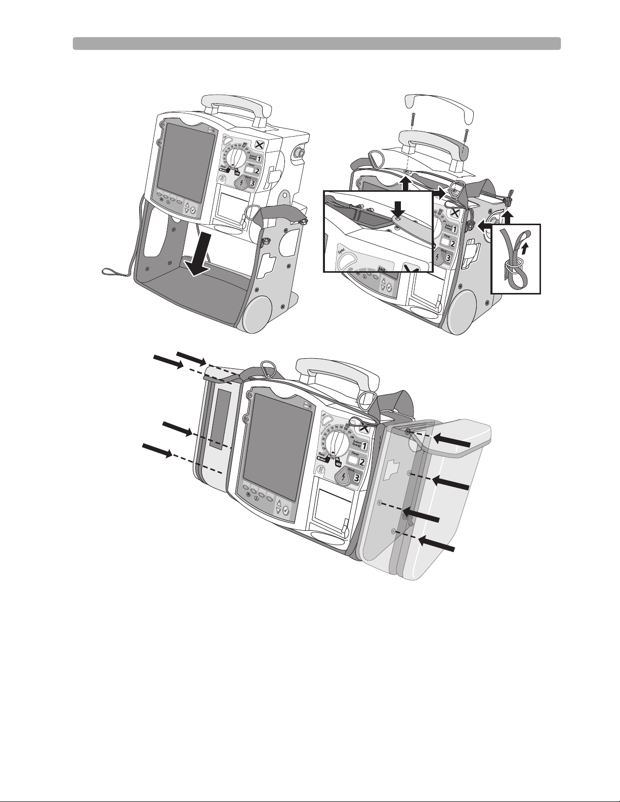
Carrying Case and Accessory Pouch Assembly
This topic should be covered for only customers who have carrying cases and accessory pouches, as
appropriate. Discuss the following procedures for carrying case assembly and recommended
accessory placement.
1. Disconnect all external power and remove all batteries.
2. Lower the device into the sleeve of the carry case. The rear base of the device fits in the sleeve
socket.
Paddle Tray
a. If paddles are connected, disconnect them from the Therapy port and remove them from the
paddle tray.
b. Remove the four T-15 screws from the tray plates.
c. Gently lift the paddle tray up, leaving all wires connected.
Handle Only
a. Remove the handle cover by pushing in on either side of the handle cover and lifting up.
b. Remove the two T-15 screws.
c. Remove the handle.
d. Gently lift the cap plate up.
3. Fold the two sleeve flaps over the top of the device, positioning them so that the screw holes are
exposed.
4. Replace the paddle tray or cap plate, as appropriate, so that the molded openings fit over the sleeve
flaps.
5. Secure the front and rear cinch straps using the metal rings provided.
6. Perform an Operational Check on the MRx.
7. Attach the side pouches using the snaps located inside the pouch pockets.
The following illustrations show carrying case and accessory pouch assembly.
18
Lesson Presentation 2 Getting Acquainted
19
2 Getting Acquainted Lesson Presentation
(
(
(
(
(
(
(
(
(
(
(
(
(
(
(
(
(
(
(
(
(
(
(
(
(
(
(
(
(
(
(
(
(
(
(
(
(
(
(
(
(
(
(
(
(
(
(
(
(
(
(
(
(
(
(
(
(
(
(
(
(
(
(
(
(
(
(
(
(
(
(
(
(
(
(
(
(
(
(
(
(
(
(
(
(
(
(
(
(
(
(
(
(
(
(
(
(
(
(
(
(
(
(
(((
(
(
(
(
(
(
(
(
(
(
(
(
(
(
(
(
(
(
(
(
(
(
(
(
(
(
(
(
(
(
(
(
(
(
(
(
(
(
(
(
(
(
(
(
(
(
(
(
(
(
(
(
(
(
(
(
(
(
(
(
(
(
(
(
(
(
(
(
(
(
(
(
(
(
(
(
(
(
(
(
(
(
(
(
(
(
(
(
(
(
(
(
(
(
(
(
(
(
(
(
(
(
(
(
(
(
(
(
(
(
(
(
(
(
(
(
(
(
(
(
(
(
(
(
(
(
(
(
(
(
(
(
(
(
(
(
(
(
(
(
(
(
(
(
(
(
(
(
(
(
(
(
(
(
(
(
(
(
(
(
(
(
(
(
(
(
(
(
(
(
(
(
(
(
(
(
(
(
(
(
(
(
(
(
(
(
(
(
(
(
(
(
(
(
(
(
(
(
(
(
(
(
(
(
(
(
(
(
(
(
(
((
(
(
(
(
(
(
((
(
(
(
(
(
(
(
(
(
(
(
(
(
(
(
(
(
(
(
(
(
(
(
(
(
(
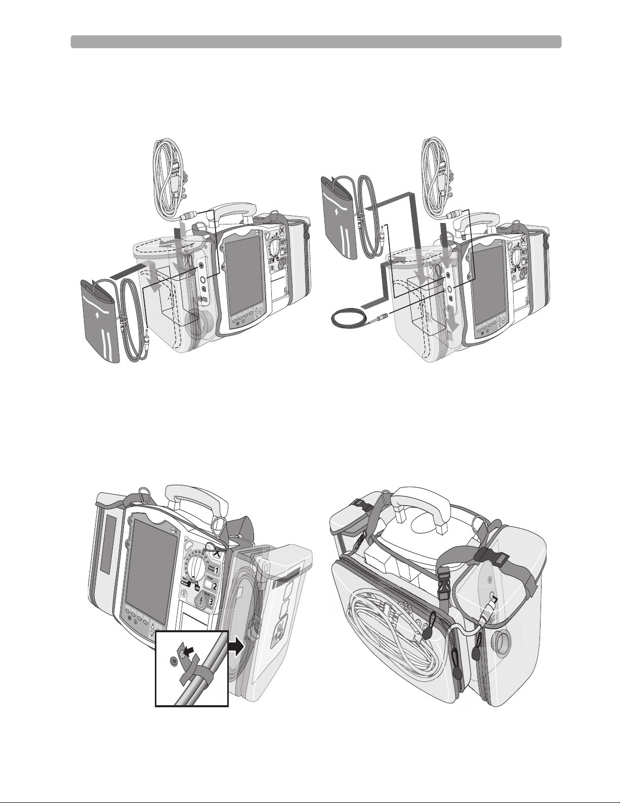
Storing Accessories
1. Store parameter cabling and accessories as shown below.
2. Attach the Therapy cable and route it through the cable fastener loop, securing the cable just below
the strain relief. (See below left.)
3. Attach the rear pouch using the buckles provided. (See below right.)
Note: Depressions are provided on the inside of the rear pouch should you wish to make a cut-out to
accommodate external power.
(
(
(
(
(
(
(
(
(
(
(
(
(
(
(
(
(
(
(
(
(
(
(
(
(
(
(
(
(
(
(
(
(
(
(
(
(
(
(
(
(
(
(
(
(
(
(
(
(
(
(
(
(
(
(
(
(
(
(
(
(
(
(
(
(
(
(
(
(
(
(
(
(
(
(
20
 Loading...