

Page 1
M3535A/M3536A
Instructor Guide
HeartStart MRx
Page 2

Page 3

Notice
About This Edition
Publication number 453564045041
Edition 1
Printed in the USA
To determine the product level version to which this
guide applies to, refer to the version level on the back
cover of this book or on the label of the User
Documentation CD-ROM that accompanied the device.
This information is subject to change without notice.
Philips shall not be liable for errors contained herein or
for incidental or consequential damages in connection
with the furnishing, performance, or use of this material.
Edition History
Edition Print Date
1 September, 2006
Copyright
Copyright © 2006
Koninklijke Philips Electronics N.V.
All rights are reserved. Permission is granted to copy and
distribute this document for your organization’s internal
educational use. Reproduction and/or distribution
outside your organization in whole or in part is
prohibited without the prior written consent of the
copyright holder.
SMART Biphasic is a registered
trademark of Philips.
®
Microstream
of Oridion Medical Ltd. Smart CapnoLine™ is a
trademark of Oridion Medical Ltd.
Q-CPR™ is a trademark of Laerdal Medical.
The HeartStart MRx contains an Ezurio PC Card with
Bluetooth
wordmark and logos are owned by the Bluetooth SIG,
Inc. and any use of such marks by Ezurio is under license.
Coverage Plus
trademarks of Steris Corp.
CidexPlus
Sterilization Products.
Other trademarks and trade names are those of their
respective owners.
and FilterLine® are registered trademarks
®
wireless technology. The Bluetooth
®
and Coverage Plus NPD® are registered
®
is a registered trademark of Advanced
Use of supplies or accessories other than those
recommended by Philips may compromise product
performance.
THIS PRODUCT IS NOT INTENDED FOR HOME
USE.
IN THE U.S., FEDERAL LAW RESTRICTS THIS
DEVICE TO SALE ON OR BY THE ORDER
OF A PHYSICIAN.
Medical Device Directive
The HeartStart MRx complies with the requirements of
the Medical Device Directive 93/42/EEC and carries the
mark accordingly.
0123
Manufacturer:
Philips Medical Systems
3000 Minuteman Road
Andover, MA 01810
Authorized EU-representative:
Philips Medizin Systeme Böblingen GmbH
Hewlett Packard Str. 2
71034 Böblingen
Germany
Canada EMC:ICES-001
China:
After Sales Service: Beijing MEHECO-PHILIPS Medical
Equipment Service Center.
After Sales Service Address: No. 208, 2nd District, Wang
Jing Li Ze Zhong Yuan, Chao Yang District, Beijing.
Postal code: 100102.
Telephone: 010-64392415.
Registration number: SFDA(I)20043211207.
Product Standard number: YZB/USA 52-21.
For the Declaration of Conformity Statement, please see
the Philips Medical web site at http://
incenter.medical.philips.com/PMSPublic. Scroll over the
Quality and Regulatory Tab located in the upper left
corner of the window. Click to select Regulatory by
Modality. Then click to select Defibrillators and select
the entry for Declaration of Conformity (DoC)
Warning
Radio frequency (RF) interference from nearby
transmitting devices may degrade the performance of the
HeartStart MRx. Electromagnetic compatibility with
surrounding devices should be assessed prior to using the
monitor/defibrillator.
.
i
Page 4

This Instructor Guide contain the following conventions:
“Voice” represents voice prompt messages
Text represents messages that appear on the display
Text represents bolded directions to the instructor that appear in the guide and
options that appear on MRx menus
[Soft key] represents soft key labels that appear on the display above the
button to which they correspond.
ii
Page 5

1Table of Contents
1 Introduction 1
2 Getting Acquainted 5
Lesson Introduction 5
Objectives 5
Time 5
Accessories Recommended 5
Lesson Presentation 6
Overview 6
Basic Orientation 6
Display View 10
Continued Use 15
Printing Waveforms 16
Return to Owner 16
Carrying Case and Accessory Pouch Assembly 18
Storing Accessories 20
Review 23
3 ECG and Arrhythmia Monitoring 25
Lesson Introduction 25
Objectives 25
Time 25
Accessories Recommended 25
Clinical Resources 25
Lesson Presentation 26
Overview 26
Monitor View 26
Preparation 27
Heart Rate and Arrhythmia Alarms 30
Displaying an Annotated ECG 35
Arrhythmia Learning/Relearning 36
Review 37
4 Semi-Automated
External Defibrillation 39
Lesson Introduction 39
Objectives 39
Time 39
Accessories Recommended 39
iii
Page 6

Clinical Resources 39
Lesson Presentation 40
Overview 40
AED View 40
Preparation 41
AED Mode 42
Review 47
5 Manual Defibrillation
and Cardioversion 49
Lesson Introduction 49
Objectives 49
Time 49
Accessories Recommended 49
Clinical Resources 49
Lesson Presentation 50
Manual Mode 50
Code View 50
Manual Defibrillation Preparation 51
Manual Defibrillation 52
Synchronized Cardioversion 54
Synchronized Shock Delivery 55
Review 57
6 Q-CPR™ 59
Lesson Introduction 59
Objectives 59
Time 59
Accessories Recommended 59
Clinical Resources 59
Lesson Presentation 60
Overview 60
Q-CPR Preparation 61
Q-CPR in Manual Defib Mode 64
Q-CPR in AED Mode 67
Review 69
7 Noninvasive Pacing 71
Lesson Introduction 71
Objectives 71
Time 71
Accessories Recommended 71
Clinical Resources 71
Lesson Presentation 72
Pacer Mode 72
iv
Page 7

Pacing View 73
Demand vs. Fixed Mode 74
Preparation 75
Demand Mode Pacing 76
Fixed Mode Pacing 78
Defibrillating During Pacing 79
Review 80
8 Pulse Oximetry Monitoring 81
Lesson Introduction 81
Objectives 81
Time 81
Accessories Recommended 81
Clinical Resources 81
Lesson Presentation 82
Overview 82
Selecting a Sensor 82
Applying the Sensor 83
Monitoring SpO
Pleth Wave 85
Setting SpO2 Alarms 86
Setting Pulse Rate Alarms 88
Disabling the SpO2 Monitoring Function 88
2
Review 90
84
9 Noninvasive Blood Pressure Monitoring 91
Lesson Introduction 91
Objectives 91
Time 91
Accessories Recommended 91
Clinical Resources 91
Lesson Presentation 92
Overview 92
Preparing to Measure NBP 93
Measuring NBP 94
Alarms 96
Review 98
10 Carbon Dioxide Monitoring 99
Lesson Introduction 99
Objectives 99
Time 99
Accessories Recommended 99
Clinical Resources 99
Lesson Presentation 100
Overview 100
v
Page 8

Preparing to Measure EtCO
Measuring EtCO
Setting Up the EtCO2 and AwRR Alarms 102
Disabling EtCO2 Monitoring 104
2
2
101
102
Review 105
11 Invasive Pressures Monitoring 107
Lesson Introduction 107
Objectives 107
Time 107
Accessories Recommended 107
Clinical Resources 107
Lesson Presentation 108
Overview 108
Pressure Measurement Set-up 108
Selecting a Pressure to Monitor 109
Pressure Waves 110
Zeroing the Pressure Transducer 111
Calibration 113
Alarms 114
Wedge 116
Pulse 116
Review 119
12 Temperature Monitoring 121
Lesson Introduction 121
Objectives 121
Time 121
Accessories Recommended 121
Lesson Presentation 122
Overview 122
Selecting a Temperature Label 122
Monitoring Temperature 123
Alarms 124
Disabling the Temperature Function 125
Review 126
13 12-Lead ECG Monitoring 127
Lesson Introduction 127
Objectives 127
Time 127
Accessories Recommended 127
Clinical Resources 127
Lesson Presentation 128
Overview 128
Preview Screen 128
vi
Page 9

Preparation 129
Acquiring the 12-Lead ECG 130
12-Lead Report 131
Accessing Stored Reports 131
Adjusting Wave Size 132
12-Lead Filters 132
Review 133
14 12-Lead ECG via Bluetooth Transmission 135
Lesson Introduction 135
Objectives 135
Time 135
Accessories Required 135
Technical Resources 135
Lesson Presentation 136
Overview 136
Setting Up for Bluetooth Transmission 137
Transmitting to a Configured Site using Bluetooth 140
Transmitting to a Fax Number 140
Transmitting Stored 12-Lead Reports 140
Transmission Status 141
Cancelling Transmission 141
Review 142
15 Vital Signs Trending 143
Lesson Introduction 143
Objectives 143
Time 143
Accessories Recommended 143
Lesson Presentation 144
Overview 144
Reviewing Trending Data 144
Tre nd i n g R e p o r t I n t er va l s 145
Scrolling in the Trending Report 145
Printing the Trending Report 145
Exiting the Trending Report 145
Review 147
16 Data Management 149
Lesson Introduction 149
Objectives 149
Time 149
Accessories Recommended 149
Lesson Presentation 150
Overview 150
Marking Events 151
vii
Page 10

Printing Events 151
Printing the Event Summary 152
Printing the Vital Signs Trending Report 152
Using Data Management - Internal Memory 153
Using Data Management - Data Card 153
Review 155
17 Maintenance 157
Lesson Introduction 157
Objectives 157
Time 157
Accessories Recommended 157
Maintenance Resources 157
Lesson Presentation 158
Overview 158
Automated Tests 159
Ready For Use Indicator 160
Shift Check 161
Weekly Sh oc k Test 162
Operational Check 163
Battery Maintenance 170
Cleaning Instructions 171
Review 174
viii
Page 11

Instructor Guide
Instruction Time
1
1Introduction
This instructor guide is designed to assist you in the delivery of end-user training on the HeartStart
MRx. It provides directions and suggestions for teaching the safe and proper operation of the device,
and is intended only for ACLS personnel thoroughly trained in the use of the device.
It is estimated that this course will require 2-5 hours to complete, depending on class size, location,
number of devices available for training, optional device parameters purchased, and student knowledge
and needs.
Guide Structure
This guide is divided into sixteen (16) lessons, as follows:
• Getting Acquainted
• ECG and Arrhythmia Monitoring
• Semi-Automated External Defibrillation
• Manual Defibrillation and Cardioversion
•Q-CPR™*
• Noninvasive Pacing*
•Pulse Oximetry*
• Noninvasive Blood Pressure*
• Monitoring Carbon Dioxide*
• Invasive Pressures*
•Temperature*
•12-Lead ECG*
• 12-Lead ECG via Bluetooth Transmission*
•Vital Signs Trending
• Data Management
• Maintenance
* This is an optional parameter with the MRx, so ensure you teach only the lessons that match the
organization’s device configuration.
1
Page 12

1 Introduction
Preparation
Prior to each class:
• Contact the organization’s training coordinator to schedule training, if applicable. Suggest train-thetrainer sessions. Make sure students understand that they must be free from other responsibilities at
the scheduled time for the duration of the course. A maximum of 10 students is recommended for
each class.
• Talk to the training coordinator (if applicable) about which device functions students will be using
on the job (AED Mode, Manual Mode, Pacing, SpO
, etc.). Use this information to select the
2
appropriate lessons and determine your lesson presentation.
• Recommend to the training coordinator that students watch the latest version of the HeartStart
MRx User Training Video or DVD prior to the instructor-based training, if available. Also, suggest
taking the HeartStart MRx Web-based User Training prior to or after the instructor-based training.
• Determine the number of devices needed for training and make arrangements to have them set up at
the scheduled time, if possible. Try not to exceed grouping 2-3 students per device.
• Determine who in the organization makes decisions about configuration. Arrange a time to discuss
the organization’s desired configuration and set up the devices used in training to that configuration.
Use the configuration worksheet available on the User Documentation CD-ROM to help you
complete the configuration procedure.
• Perform an Operational Check on each device to be used in training prior to
training. Refer to the
latest version of the HeartStart MRx Instructions For Use to complete the Op Check, if necessary.
• Try to have fully charged batteries and external power available if needed.
• Try to have one simulator for each device to be used in training, as well as extra batteries for the
simulators.
• Try to have appropriate sets of parameter accessories, cables, etc. for each device.
• Try to have one copy of the latest HeartStart MRx User Training Workbook available for each
student, if possible. The workbook contains a similar lesson flow to the guide, but only a summary
of the content. Students can use the workbook to follow your instruction. Be sure to familiarize
yourself with the workbook before
you teach. It is available on the User Documentation CD-ROM
that comes with the MRx.
• As appropriate and if possible, try to have one copy of each application note available for each
student either before, during, or after the training. These notes relate to several lessons in the guide.
They can be found on the User Documentation CD-ROM, as well as:
– www.medical.philips.com/goto/productdocumentation
• If possible, try to have one set of latest version of the HeartStart MRx Quick Reference Cards
available for the training.
2
Page 13

Teaching Guidelines
Consider the following guidelines for delivering the MRx training.
• Have students identify themselves and their role and/or responsibilities. This information gives you
a better idea of what lessons/topics are suitable or most important for your audience.
• Provide a brief overview of the course structure and what is covered in each lesson.
• Advise students to read the HeartStart MRx Instructions For Use for details on device features and
information not covered in the classroom:
– Device intended use
– Device and accessory set-up
– Configuration
– Device disposal
–Troubleshooting
– Specifications and safety
•For each lesson:
– Introduce the learning objectives (as listed in the guide), advise on how much time it will take to
complete a lesson, and point out what related resources (e.g., application notes) are available to
students for further education.
– Present the lesson content. Annotate and/or highlight material (in your copy of the guide) to
ensure you stress information that you feel is important to your students’ needs. Note that
instructor directions are in bold. Look for suggestions that raise the level of student interaction.
There is also space for additional points or notes to be made at a topical level, depending on
students’ needs.
– Review the content presented by completing the review questions at the end of each lesson. Note
that answers to the questions are in bold.
1 Introduction
• Periodically ask for questions to ensure comprehension.
• Periodically ask questions to engage students and increase learning effectiveness.
• Take breaks over the course of the training (if time allows) to ensure learning effectiveness.
• At the completion of a class, use the Skills Checklist to test students on various functions and
features of the MRx.
Safety Considerations
Some warnings and cautions specific to a particular feature of the HeartStart MRx are provided in this
guide; however, you and students should reference the Instructions For Use for a complete description
of all safety warnings and cautions. Nonetheless, reinforce the fact that the MRx is a live device that can
deliver high-energy therapy and should not be used by untrained personnel. Operation by untrained
personnel can result in injury or death.
3
Page 14

1 Introduction
Additional Documentation and Training
Available documentation and training for the HeartStart MRx includes:
• HeartStart MRx Instructions for Use - provides the most comprehensive review of MRx
functionality and operation for students. It is available on the User Documentation CD-ROM or
may be purchased in hardcopy form.
• HeartStart MRx Quick Reference Cards - provide visual, step-by-step summaries of key functions,
parameters, and related operation
– Controls, Connections and Indicators
– Ready For Use Indicator
–Using Alarms
–Monitoring ECG
–Monitoring SpO
–Monitoring NBP
–Monitoring CO
– Monitoring Invasive PressuresNoninvasive Pacing
–Q-CPR
– 12-Lead ECG
–Operational Check
2
2
• HeartStart MRx Web-based User Training - provides a comprehensive self-paced training on the
same content found in the instructor guide. It is located on Philips Medical Systems’ web site at:
www.medical.philips.com/goto/mrxtraining.
Students need to enter the training access password meetMRx to get started.
• HeartStart MRx User Training Video - provides a 50-minute overview of MRx functions, features,
and operation. The video serves as valuable preparation for the classroom or as a refresher after the
training.
•Application Notes
– Arrhythmia Monitoring Algorithm
– AED Algorithm
– SMART Biphasic
– Noninvasive Pacing
– Philips Pulse Oximetry
– Noninvasive Blood Pressure Monitoring
– Uses of Capnography - The Microstream® Method
– Q-CPR™ Measurement and Feedback
• 12-Lead Algorithm Data Sheet
• Philips 12-Lead Algorithm Physician’s Guide, available from IntelliVue Information Center - User
Materials under Patient Monitoring at http://www3.medical.philips.com/en-us/doc_downloads/
docdownload.asp
4
Page 15

Instructor Guide
Lesson Introduction
Introduce the lesson, including the learning objectives, estimated time to complete, and applicable
resources.
This lesson provides an overview of the HeartStart MRx controls, indicators, operational modes, and
display views. It also provides general information on use of the device.
2
2Getting Acquainted
Objectives
Upon completion of this lesson, students should be able to:
1. Identify the physical features, controls, and indicators of the MRx.
2. Identify the purpose of various controls and indicators.
3. Identify the display view characteristics associated with MRx’s operating modes.
4. Identify the correct procedure for responding to an alarm.
Time
15-25 minutes
Accessories Recommended
•Simulator
•Hands-free cable
• Multifunction electrode pads
• 3-, 5-, or 10-Lead monitoring electrodes
• Optional Pacing, SpO
accessories
, CO2, NBP, invasive pressure, temperature, and/or Q-CPR parameter
2
5
Page 16

2 Getting Acquainted Lesson Presentation
Lesson Presentation
Overview
Describe the high-level features of the MRx.
• It is designed for a variety of needs.
• It has controls, indicators, and menus organized to facilitate ease of use.
• It displays information specific to the current task.
Basic Orientation
Introduce the physical features, controls, and indicators on the front, left, right, top, and back panels
of the MRx. Also, discuss the lithium ion battery.
Suggestion: Have students identify the features, controls, and indicators on their devices and the
battery while following your orientation.
NOTE: Consider not turning on the MRx during your initial orientation so students focus on each
panel and NOT the display. Then, turn on the device to illustrate display output of features and
controls.
Front Panel
Controls and indicators on the front panel are organized by function, with the most general function
buttons located along the left and bottom sides of the display, defibrillation controls to the right of the
display, and soft keys immediately below the display.
Therapy Knob
Serves as the MRx power switch and can be set to:
• AED - to enable AED Mode for semi-automated external defibrillation and optional Q-CPR
parameter.
• Off
• Monitor - to enable Monitor Mode for 3- or 5-Lead ECG monitoring, optional 12-Lead ECG
acquisition, or monitoring of optional parameters such as SpO
• Pacer (optional) - to enable Pacer Mode for demand or fixed mode pacing.
• Manual Defib - to enable Manual Mode for asynchronous or synchronous defibrillation
(cardioversion) at the selected energy setting and optional Q-CPR parameter.
Energy settings are 1-9, 10, 15, 20, 30, 50, 70, 100, 120, 150, 170, and 200 Joules. If the device is
equipped with optional Pacing, energy settings are 1-10, 15, 20, 30, 50, 70, 100, 120, 150, 170, and
200 Joules.
, CO2, and NBP.
2
6
Page 17

Lesson Presentation 2 Getting Acquainted
General Function Buttons
Control monitoring or non-critical resuscitation activities
• Mark Event - inserts a time-stamped annotation in the Event Summary Report to note events as
they occur, including drug administration. A Mark Event button label appears at the top left corner
of the display.
• Lead Select - changes the ECG lead in Wave Sector 1; cycles through the available ECG waves,
changing the displayed wave and label. The list of available ECG waves is based on the current lead
set and device configuration, and includes pads or paddles if the corresponding cable is connected to
the MRx.
• Alarm Pause - pauses all visual and audible physiological alarms and audible inops for the
configured time interval. At the end of the pause interval, each alarm returns to its previous setting
(On or Off). Also returns alarms to their previous settings.
• Print - initiates a continuous print-out of the primary ECG and the waveform displayed in Wave
Sector 2, either real-time or with a 10-second delay, depending on device configuration.
• Summary - displays a menu from which you can print the current or most recent Event Summary
report or Vital Signs Trending Report.
• Menu Select - brings up the current menu or confirms a menu selection.
• Navigation - display the current menu just like Menu Select button does; move to the next or
previous item in a list; increase or decrease numbers or values in a sequence; may be held down to
accelerate through the available choices.
Defibrillation Controls
• Therapy Knob - enables AED or selects an energy for Manual Mode defibrillation or cardioversion.
• Charge - charges the defibrillator to the selected Manual Defib energy setting. Used only in Manual
Mode. Defibrillator charges automatically in AED Mode.
• Shock
– delivers a shock through multifunction electrode pads or switchless internal paddles. In AED
Mode, a 150J shock is delivered. In Manual Mode, the shock is delivered at the selected energy
setting.
– When external paddles or switched internal paddles are used, once the MRx is fully charged, the
shock is delivered by pressing the Shock button(s) on the paddles.
NOTE: Internal paddles should only be discussed with clinicians dealing with open chest
defibrillation.
• Sync - toggles between asynchronous and synchronous (cardioversion) defibrillation.
Soft Keys
Perform functions presented as labels appearing immediately above the keys on the display. Labels (and
related functions) change based on the mode of operation.
7
Page 18

2 Getting Acquainted Lesson Presentation
Indicators
Provide a visual display of device status
Ready For Use (RFU)
• A blinking black hourglass symbol indicates:
– Shock, pacing, and ECG functions are ready for use.
– Sufficient battery power is available for device operation.
– An installed battery is being charged, assuming the presence of external power (AC or DC).
• A blinking red “X” and a periodic audio chirp indicate:
– No battery is present or a low battery condition.
– The device can be used in a low battery condition, but its operation time is limited. If the device
is running only on external power, it takes longer to charge. If a battery is inserted and charging,
the audio chirp is not present.
• A solid red “X” and a periodic audio chirp indicate:
– A failure that may prevent delivery of defibrillation therapy, pacing, or ECG acquisition. When
turned on, the device displays an error message for the first critical failure detected. Consider
doing an Operational Check if the device is in this state to isolate the failure.
Side Panels
• A solid red “X” without periodic audio chirps indicates:
– Either no power is available or a catastrophic failure has occurred.
– The device cannot power on. If, after power is supplied, the indicator reverts to the blinking black
hourglass symbol, the device is once again ready for use.
Note the following: The RFU indicator may briefly display a solid red "X" when initially turning the
device on, when switching between clinical and non-clinical operating modes, and at the start of any
automated test.
External Power - lights green if power is being provided by an external AC or DC power source;
momentarily goes out when charging for defibrillation with a charged battery installed, as the device
switches power source to the battery for a faster charge time.
The front panel also includes the printer door and latch, speaker (for audible alarms and AED voice
prompts), and the display (covered in detail later).
• The left panel has:
– Ports for monitoring cables (if ordered), including ECG (for 3-, 5-, or 10-Lead patient cable),
pulse oximetry (SpO2), noninvasive blood pressure (NBP), two invasive pressures, temperature,
and carbon dioxide (CO
* For CO
, there is an Inlet port for monitoring tubing and an Outlet port when administering
2
)*.
2
anesthetic gases.
– An ECG Out jack to connect to an external monitor.
• The right panel has:
– A therapy port for paddles (external or internal) or multifunction electrode pads and/or Q-CPR
Compression Sensor.
– A slot for a data card to transfer patient information.
8
Page 19

Lesson Presentation 2 Getting Acquainted
Top Panel
The top panel has a handle and basic operating instructions. Optional external (adult/pedi) paddles
also reside here, if present.
NOTE: Be sure to demonstrate access to the pediatric paddles.
Back Panel
The back panel has:
• Two compartments for lithium ion batteries. Compartment B also used to connect an AC power
module.
NOTE: Be sure to demonstrate how to take batteries in and out of the compartments.
• A DC Power Input port.
• An RS-232 serial port for 12-Lead ECG transmission.
• A LAN port for future use.
M3538A Lithium Ion Battery
• Has a fuel gauge with 5 LED indicators, each representing a charge of approximately 20% of
capacity. Press the fuel gauge button to illuminate the fuel gauge.
• Should be used as the primary power source, with AC/DC as a secondary source, if desired. If an
AC/DC power module is used as the only power source, the MRx takes longer to charge to the
desired energy level and, in the event of power loss, all settings reset to the default settings and a new
incident is created when power is returned. All stored data remains intact and can be found by
retrieving the previous incident. Keep your unit charged.
o
• A new, fully-charged M3538A battery, operating at room temperature 25
approximately 5 hours of monitoring, with ECG, SpO
, CO2, temperature, two invasive pressures
2
C(77oF), provides
monitored continuously, NBP measured every 15 minutes, and 20 200J discharges. A fully charged
new battery provides approximately 3.5 hours of monitoring, with ECG, SpO
, CO2, temperature,
2
two invasive pressures monitored continuously, NBP measured every 15 minutes, and pacing at
180ppm at 160mA.
• Battery life depends on the frequency and duration of use. When properly cared for, useful life is
approximately 2 years. To optimize performance, a fully (or nearly fully) discharged battery should
be charged as soon as possible.
9
Page 20

2 Getting Acquainted Lesson Presentation
Additional points/notes:
________________________________________________________________________________
________________________________________________________________________________
________________________________________________________________________________
________________________________________________________________________________
Display View
Introduce the display view characteristics of the MRx, starting with a brief look at the various
operating modes. Attach a simulator (set to a normal sinus rhythm), 3-, 5-, or 10-Lead ECG set, and
all available parameter accessories to the MRx. Feel free to switch between modes to illustrate
display view characteristics; however, consider spending most of your time in Monitor Mode, as it
provides the most comprehensive view. You will cover details of the AED, Code, and Pacing views
in related lessons later in this guide.
Suggestion: Have students set up their devices with accessories they will use and turn them on to the
operating mode(s) you cover to follow your display view introduction. Ask students what they see in
each display view you cover versus just telling them what they see.
Operating Modes
The MRx has four clinical modes of operation, each with a customized display view function being
performed:
Note: Upon returning to a clinical mode from a non-clinical mode such as Configuration or Data
Management, all settings are re-set to the device’s default values.
Mode of Operation Display View Description
Monitor Mode Monitoring View or
12-Lead View
AED Mode AED View Analyzes ECG and, if necessary, performs
Manual Defib Mode Code View Performs asynchronous and synchronous
Pacer Mode Pacing View Performs demand or fixed mode pacing,
Monitors ECG, takes an optional 12-lead
ECG, and monitors optional parameters
such as SpO
Pressures, and Temperature, and for
viewing Vitals Signs Trending data
semi-automated external defibrillation and
optional Q-CPR
defibrillation (cardioversion) and optional
Q-CPR, and monitors ECG
and monitors ECG
, EtCO2, NBP, Invasive
2
10
Page 21

Lesson Presentation 2 Getting Acquainted
Password Security
Access to Manual Defib Mode and Pacer Mode may be password protected if configured. If enabled,
you are prompted to enter the password when you move the Therapy Knob to either the Pacer position
or an energy selection. Use the Navigation buttons to select the password numbers, select Done, and
then press Menu Select to complete the entry. The Charge button and the [Start Pacing] soft
key remain inactive until the password is entered. AED Mode is always available without a password.
Note the following: Use of the Manual Therapy Security password requires the clinician to know and
remember the password, as defined in Configuration. Failure to enter the correct password prevents
manual defibrillation delivery or pacing therapy. Prior to selecting this Configuration option, review
this potential risk with your Risk Manager.
Display Layout
The MRx display layout is segmented as follows:
General Status
At the top, this area contains:
• Mark Event button label
•Date and time
• Battery icons
– Labeled “A” and “B” to match battery compartments on back panel.
– Display current available battery power, ranging from hollow (fully discharged) to full (fully
charged). If an AC Power Module is in Compartment B, the No Battery icon is displayed.
• Audio recording icon - If the option is enabled, an audio recording icon displays to the left of the
battery icons in all clinical modes to indicate the audio recording status.
• Patient information
Some modes of operation permit patient information entry via a menu choice. If no information is
entered, the patient category is defaulted to Adult, unless configured otherwise, and the pacing status
is set to Non-Paced, unless the Paced status has been previously set to Paced for an internally paced
patient or the MRx is pacing the patient. In Pacer Mode, Paced status is not displayed.
• Patient name -If entered, the patient’s name will appear above the patient type and paced status.
• Inop statements - appear in top left of display if equipment problems occur
• ECG/HR alarm status - alarm messages communicate arrhythmia alarms, as well as overall alarm
status (alarms off, alarms paused)
• Event Timer - communicates elapsed time for the current patient incident
Wave Sectors
• MRx displays up to 4 wave sectors with a predetermined waveform, when powered on in Monitor,
Manual, or Pacer Mode.
• A dashed line (in a wave sector) or empty wave sector indicates waveform source not connected to
MRx.
• Sectors may contain a variety of information, as appropriate to the parameter, view, and task; ECG
wave sectors contain a calibration bar.
11
Page 22

2 Getting Acquainted Lesson Presentation
Wave Sector 1
• Will only contain an ECG waveform (used by the arrhythmia, heart rate derivation, and AED
analysis algorithms); the waveform may be acquired through the therapy port for pads/paddles or
the monitoring port for 3-, 5-, or 10-Lead electrodes.
• If the configured source is not connected to the device when turned on, the first valid ECG source is
displayed in Wave Sector 1. Once the source is available, it automatically populates Wave Sector 1.
• The displayed lead/source is controlled primarily by the Lead Select button, although the Displayed
Wave s menu can be used.
• This sector includes R-wave detection.
• When monitoring using a 3-lead ECG set, the MRx displays only one ECG lead at a time.
• If Pads are configured as the primary ECG source for Wave Sector 1, the ECG patient cable must be
connected to the MRx and to the monitoring electrodes in order to change the ECG source to a
Leads selection.
Wave Sectors 2-4
• Automatically populate when parameter sources (cables/tubing) are connected to the MRx. Q-CPR
compression waveform automatically populates on 150J Manual Defib Mode setting.
• If parameter source is the configured choice of a particular wave sector, it is displayed in that sector.
• If you connect a parameter source that is not configured to be displayed, it displays in the first
empty wave sector. If you subsequently connect the configured parameter source, it replaces the
current parameter. For invasive pressures, you should label your waveforms as they are connected to
avoid possible confusion..
• Displayed lead/source is controlled by the Displayed Wave s menu.
• Wave Sectors 2 and 4 may contain a cascaded ECG.
Parameter Blocks
• Provide measurements for displayed waveforms and monitored parameters. The position of most
parameters are in fixed locations depending upon the options which were included in your
HeartStart MRx.
• Block 1 always contains heart rate and HR alarm settings; may display Pulse, Temp, and NBP
schedule, measurements, and alarm settings.
• Block 2 may contain Invasive Pressures, SpO
, EtCO2, and Airway Respiration Rate (AwRR)
2
measurements and related high/low alarm limit settings; “-?-” is displayed until a valid measurement
is obtained; settings may contain the Alarms Off icon. Block 2 may also contain Q-CPR
compression and ventilation values.
• Invasive Pressures, Temp, SpO
, and EtCO2 measurements are activated when associated cable/
2
tubing is connected; if a cable/tubing is disconnected, a prompt message requests approval to turn
off the measurement.
12
• Alarm messages appear in the space above each numeric value, replacing a parameter label.
Suggestion: Have students disconnect and reconnect parameter accessories to see how parameter
blocks are affected. Ask students what they see when detaching and attaching an accessory cable or
tubing.
Page 23

Lesson Presentation 2 Getting Acquainted
Soft Key Labels
• Correspond to soft key buttons.
• Change according to the current display view and function.
• Grey text labels indicate inactive soft keys (e.g., Disarm in Manual Mode).
Suggestion: Switch between modes to show different labels, with students following along.
Display Menus
• Provide controls and options specific to each function.
• Accessible through Menu Select and Navigation buttons.
• Used to adjust volume, select waveforms for display, set alarms, schedule measurements, enter
patient information, perform an Operational Check, generate reports, etc.
• Press Menu Select button to activate selections; select Exit to close menus without activating
selections.
Suggestion: Access different menu options to illustrate various menu functionality (e.g., changing
waveform for a sector, the patient’s age, alarm limits, etc.). If you access the Patient Info menu,
point out that a patient’s full name is entered using 2 alphabetical lists, one to enter last name,
followed by another to enter first name. When each name is complete, select Done. When entering
names, follow your organization’s or HIPPA regulations.
Message Windows
• Provide status information.
• Alert you to an error or a potential problem.
• Direct you to take action.
• Use the Navigation and Menu Select buttons to respond to messages.
High Contrast Display
• Provides a High Contrast view to optimize visibility of the MRx display when used in bright
sunlight.
• Display appears with a yellow background and all other screen elements appearing in black or shades
of gray.
•Select High Contrast On from the Main Menu to enable the feature.
Note the following: The High Contrast view does not display the colors red or blue, therefore, be sure
the MRx is configured correctly with the appropriate parameter color settings.
Suggestion: Have students set their devices to the High Contrast view any time during your
discussion.
13
Page 24

2 Getting Acquainted Lesson Presentation
Additional points/notes:
________________________________________________________________________________
________________________________________________________________________________
________________________________________________________________________________
________________________________________________________________________________
________________________________________________________________________________
________________________________________________________________________________
Responding to Alarms
Create an alarm condition and cover the following steps to respond to the condition.
1. Attend to the patient.
2. Identify the alarm(s) indicated.
3. Silence the alarm(s). When a physiological alarm is announced, the Audio Pause label displays
above the Navigation and Menu Select buttons. Pressing any of these buttons silences the audio for
all active alarms while you are attending to the patient. If the alarming condition continues to
exist, it will re-alarm in two minutes. Silencing a specific alarm does not prevent another alarm
condition from sounding. If you also silence the second alarm, it resets the two-minute audio pause
for all active alarms.
When an INOP is announced without a concurrent physiological alarm, the Audio Off label
displays above the Navigation and Menu Select buttons. Pressing any of these buttons silences the
audio for all active alarms while you are attending to the patient. INOPs do not reannunciate after
pressing audio off.
4. Address the alarm condition with one of the following options:
– Acknowledge - For latching alarms, acknowledge clears the alarm condition when the condition
no longer exists.
– New Limits - Adjust the parameter limits accordingly.
– Alarms Off - Turns the monitoring parameter’s alarms off and prevents real-time print strips.
The alarm message is no longer displayed, and the Alarm Off icon appears next to the parameter
value.
Note the following: Turning off alarms turns them off indefinitely.
– Although the Alarm Pause button can be used when responding to alarms, the response
procedures described above are recommended. Alarm Pause removes audio and visual indications
of active alarm conditions as well as inhibiting indications of new alarm conditions.
– A potential hazard exists if different alarm limits are used for the same or similar equipment in
any single area.
– Confirm the alarm limits are appropriate for the patient each time there is a new patient incident.
14
Page 25

Lesson Presentation 2 Getting Acquainted
– Do not set alarm limits to such extreme values that render the alarm system useless.
Suggestion: Note that you will also cover alarm limits in detail in the ECG and Arrhythmia
Monitoring lesson later in the training and students will be able to practice with alarm conditions at
that time.
Additional points/notes:
________________________________________________________________________________
________________________________________________________________________________
________________________________________________________________________________
________________________________________________________________________________
Continued Use
Cover the characteristics associated with MRx’s continued use feature.
• Activated once a patient event is started.
• Facilitates continued treatment of the same patient by retaining current settings and the patient
record when the MRx is turned off for less than 10 seconds or switching between modes (e.g.,
Monitor, AED, and Manual Defib).
• MRx retains the most recent settings, including:
–Alarm settings
– Wave Sector settings
–Event Timer
– QRS, alarm tone, and voice prompt volumes
–ECG gain
– Pacing settings
– Patient record in the Event Summary Report; new data is appended to the record
• This feature will not function if all power sources (battery and external AC/DC power modules) are
removed from the device, even briefly.
Suggestion: Have students shut off MRx and turn it back on within 10 seconds. Then, ask them to
state some of the settings that are retained. Consider having students complete this task before
giving them the above list of retained settings.
15
Page 26

2 Getting Acquainted Lesson Presentation
Printing Waveforms
Describe waveform printing characteristics and procedures.
• Obtain a continuous printout of the primary ECG and one additional waveform on a 50mm
printer.
• Obtain a continuous printout of the primary ECG and two additional waveform on a 75mm
printer.
• Certain waveforms (including invasive pressures and CO
• Printouts are generated either real-time or with a 10-second delay, depending on your
configuration.
To change wave forms for the second wave printed with a 50mm printer:
1. Press the Menu Select button.
2. Using the Navigation buttons, select the Printed Waves option and press Menu Select.
3. Using the Navigation buttons, select the wave form you want to print in Wave 2 and press Menu
Select.
To change wave forms for the second or third wave printed with a 75mm printer:
1. Press the Menu Select button.
2. Using the Navigation buttons, select the Printed Waves option and press Menu Select.
3. Using the Navigation buttons, select Wave 2 or Wave 3 and press Menu Select.
4. Using the Navigation buttons, select the wave form you want printed and press Menu Select.
5. Repeat Steps 2 through 4 for the other printed wave.
Return to Owner
) include scale indications on the printout.
2
16
Discuss the Return to Owner feature and demonstrate how to enable and disable it.
• Lets the MRx owner specify a loan period, after which the MRx borrower is reminded to return the
device to its owner.
• Password protected in Configuration. Each device should have a unique password.
• Monitoring and defibrillation functions are suspended while the Return to Owner set-up screen is
displayed. Alarms Off is indicated on the display. Monitoring and defibrillation functions will
return when exiting the Return to Owner screen
• The appearance of the loan expiration message does not disable monitoring and defibrillation
functionality.
To e na bl e t hi s f ea tu re :
1. Press the Menu Select button.
2. Select Other and press Menu Select.
3. Select Return To Owner and press Menu Select.
4. Press the [Activate] soft key.
Page 27

Lesson Presentation 2 Getting Acquainted
5. Enter the number of days in the loan period and press Menu Select.
6. Press the [Exit Return-To] soft key.
To disable this feature:
1. Press the Menu Select button.
2. Select Other and press Menu Select.
3. Select Return To Owner and press Menu Select.
4. Press the [Deactivate] soft key.
5. Enter the password and press Menu Select.
6. Press the [Exit Return-To] soft key.
Additional points/notes:
________________________________________________________________________________
________________________________________________________________________________
________________________________________________________________________________
________________________________________________________________________________
17
Page 28

2 Getting Acquainted Lesson Presentation
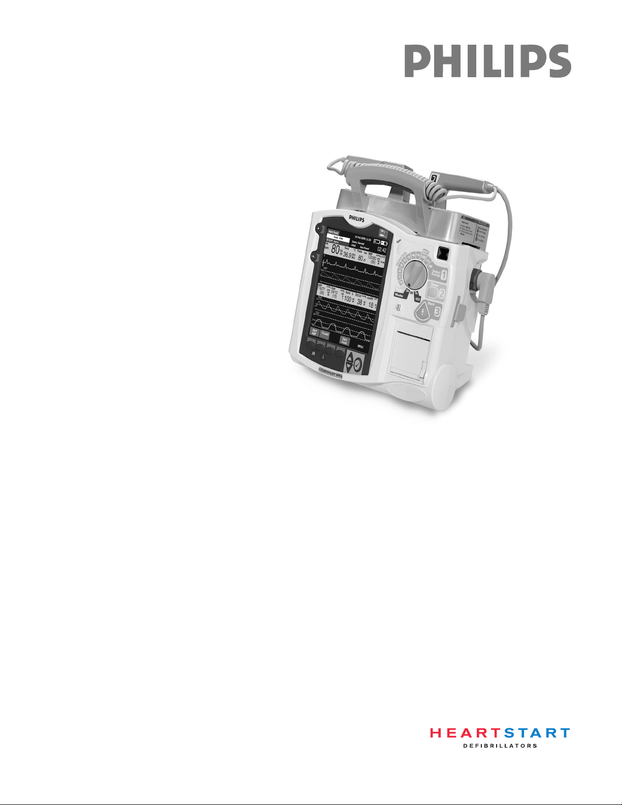
Carrying Case and Accessory Pouch Assembly
This topic should be covered for only customers who have carrying cases and accessory pouches, as
appropriate. Discuss the following procedures for carrying case assembly and recommended
accessory placement.
1. Disconnect all external power and remove all batteries.
2. Lower the device into the sleeve of the carry case. The rear base of the device fits in the sleeve
socket.
Paddle Tray
a. If paddles are connected, disconnect them from the Therapy port and remove them from the
paddle tray.
b. Remove the four T-15 screws from the tray plates.
c. Gently lift the paddle tray up, leaving all wires connected.
Handle Only
a. Remove the handle cover by pushing in on either side of the handle cover and lifting up.
b. Remove the two T-15 screws.
c. Remove the handle.
d. Gently lift the cap plate up.
3. Fold the two sleeve flaps over the top of the device, positioning them so that the screw holes are
exposed.
4. Replace the paddle tray or cap plate, as appropriate, so that the molded openings fit over the sleeve
flaps.
5. Secure the front and rear cinch straps using the metal rings provided.
6. Perform an Operational Check on the MRx.
7. Attach the side pouches using the snaps located inside the pouch pockets.
The following illustrations show carrying case and accessory pouch assembly.
18
Page 29
Lesson Presentation 2 Getting Acquainted
19
Page 30
2 Getting Acquainted Lesson Presentation
(
(
(
(
(
(
(
(
(
(
(
(
(
(
(
(
(
(
(
(
(
(
(
(
(
(
(
(
(
(
(
(
(
(
(
(
(
(
(
(
(
(
(
(
(
(
(
(
(
(
(
(
(
(
(
(
(
(
(
(
(
(
(
(
(
(
(
(
(
(
(
(
(
(
(
(
(
(
(
(
(
(
(
(
(
(
(
(
(
(
(
(
(
(
(
(
(
(
(
(
(
(
(
(((
(
(
(
(
(
(
(
(
(
(
(
(
(
(
(
(
(
(
(
(
(
(
(
(
(
(
(
(
(
(
(
(
(
(
(
(
(
(
(
(
(
(
(
(
(
(
(
(
(
(
(
(
(
(
(
(
(
(
(
(
(
(
(
(
(
(
(
(
(
(
(
(
(
(
(
(
(
(
(
(
(
(
(
(
(
(
(
(
(
(
(
(
(
(
(
(
(
(
(
(
(
(
(
(
(
(
(
(
(
(
(
(
(
(
(
(
(
(
(
(
(
(
(
(
(
(
(
(
(
(
(
(
(
(
(
(
(
(
(
(
(
(
(
(
(
(
(
(
(
(
(
(
(
(
(
(
(
(
(
(
(
(
(
(
(
(
(
(
(
(
(
(
(
(
(
(
(
(
(
(
(
(
(
(
(
(
(
(
(
(
(
(
(
(
(
(
(
(
(
(
(
(
(
(
(
(
(
(
(
(
(
((
(
(
(
(
(
(
((
(
(
(
(
(
(
(
(
(
(
(
(
(
(
(
(
(
(
(
(
(
(
(
(
(
(
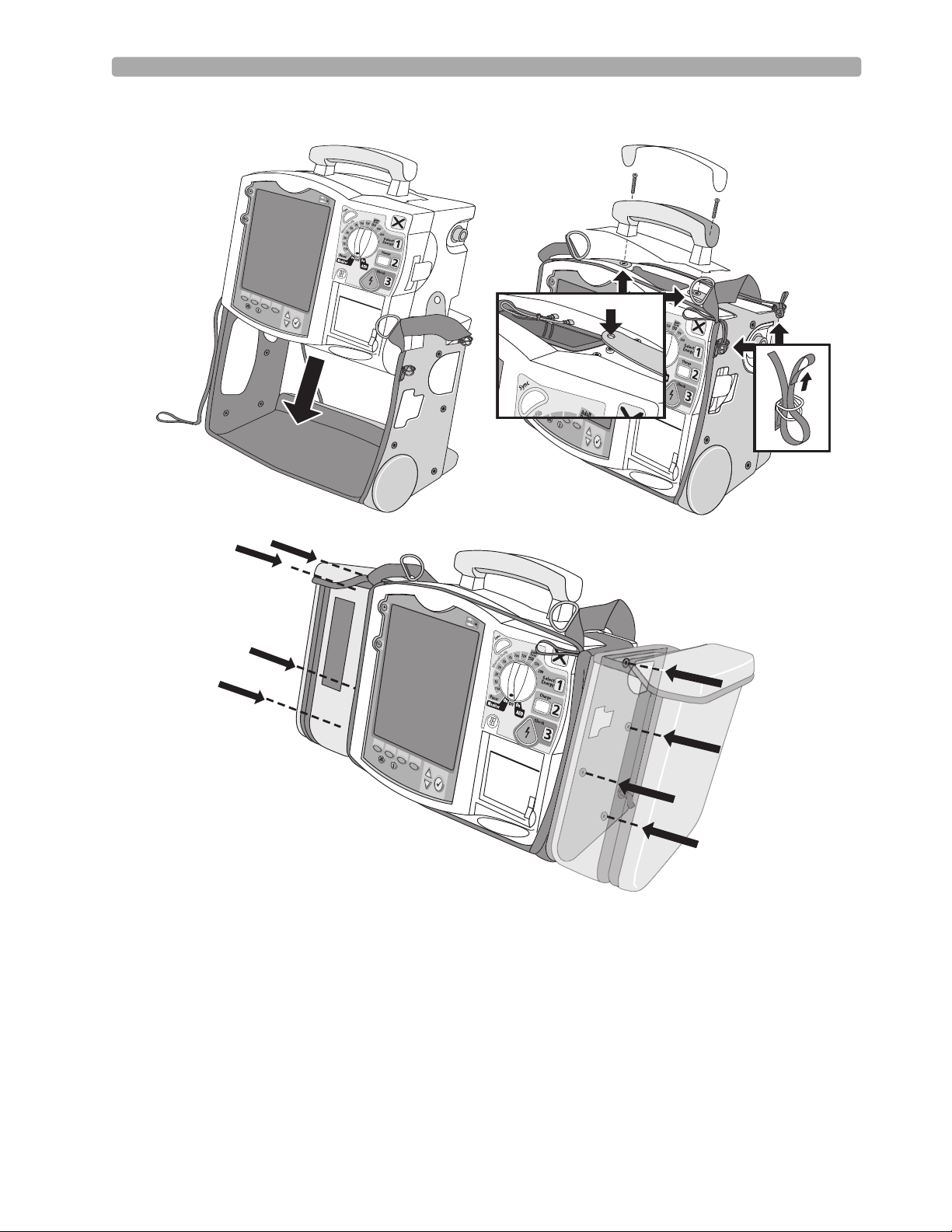
Storing Accessories
1. Store parameter cabling and accessories as shown below.
2. Attach the Therapy cable and route it through the cable fastener loop, securing the cable just below
the strain relief. (See below left.)
3. Attach the rear pouch using the buckles provided. (See below right.)
Note: Depressions are provided on the inside of the rear pouch should you wish to make a cut-out to
accommodate external power.
(
(
(
(
(
(
(
(
(
(
(
(
(
(
(
(
(
(
(
(
(
(
(
(
(
(
(
(
(
(
(
(
(
(
(
(
(
(
(
(
(
(
(
(
(
(
(
(
(
(
(
(
(
(
(
(
(
(
(
(
(
(
(
(
(
(
(
(
(
(
(
(
(
(
(
20
Page 31

Lesson Presentation 2 Getting Acquainted
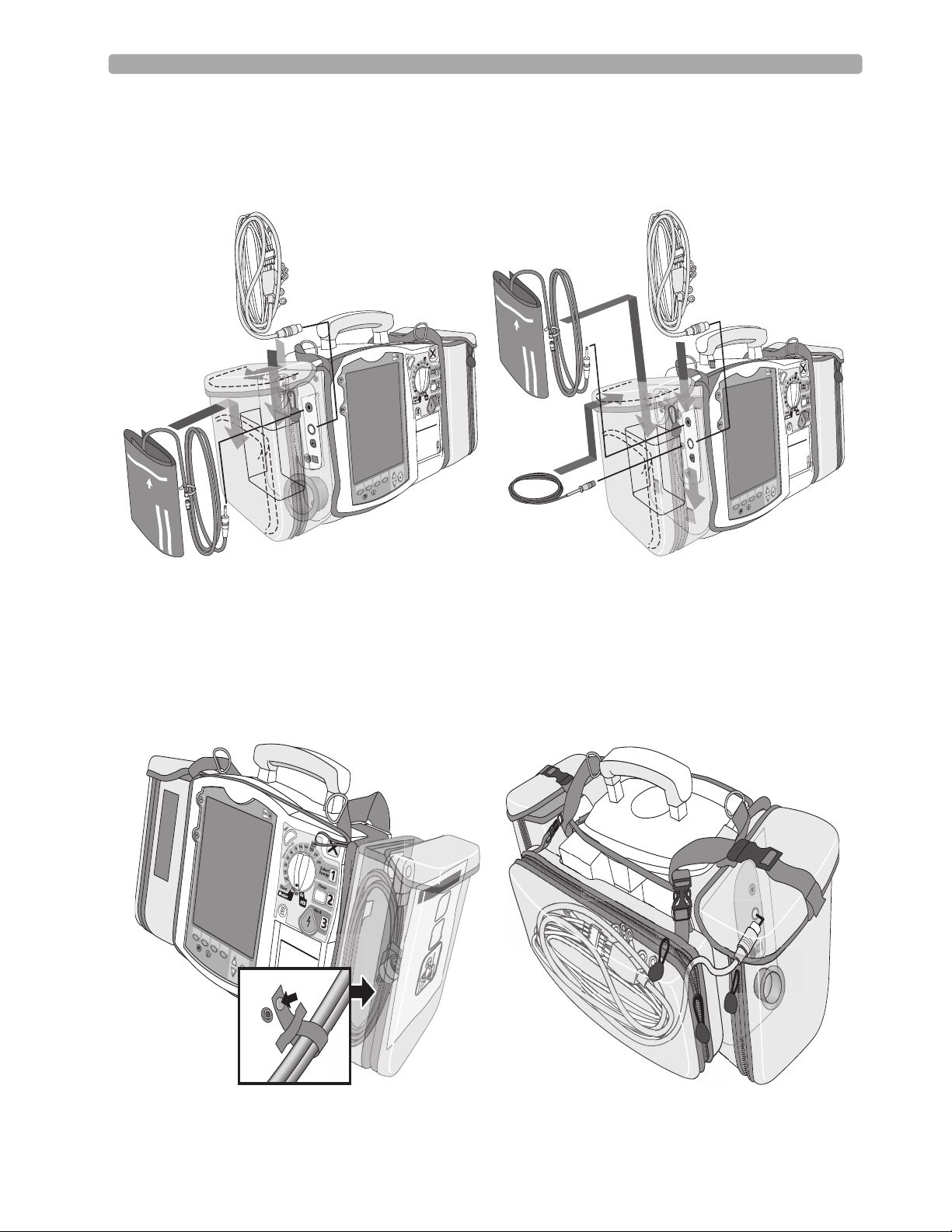
Here are recommended carry bag storage instructions for Q-CPR accessories for easy access.
Option 1
PHILIPS
Option 2
PHILIPS
Suggestion: Have students set up the carrying case and accessory pouches during your instruction.
21
Page 32

2 Getting Acquainted Lesson Presentation
Additional points/notes:
________________________________________________________________________________
________________________________________________________________________________
________________________________________________________________________________
________________________________________________________________________________
________________________________________________________________________________
22
Page 33

Review 2 Getting Acquainted
Review
Have students answer the following questions individually or as a group. (Correct answers are in
bold.)
1. Identify at least three controls or buttons on the MRx involved with defibrillation. (Therapy
Knob, Charge button, Shock button, Sync button)
2. What does a solid red "X" and periodic audio chirp indicate on the RFU?
a. No battery is present (blinking red "X" and chirp)
b. No power is available (solid red "X" and no chirp)
c. A low battery condition (blinking red "X" and chirp)
d. Defibrillation therapy may not be available
3. The arrhythmia algorithm uses the ECG in which Wave Sector for analysis?
a. 1
b. 2
c. 3
d. all of the above
4. True or false? You can select the ECG lead for Wave Sector 2 using either the Lead Select button or
Displayed Wa ve s menu. (False - You can only use the Displayed Waves menu to select the ECG
lead for Wave Sector 2.)
5. True or false? You should respond to alarms primarily by pressing the Alarm Pause button. (F - You
should respond to alarms by acknowledging them and changing limits, if needed vs. pressing the
Alarm Pause button.)
23
Page 34

Page 35

Instructor Guide
Lesson Introduction
Introduce the lesson, including the learning objectives, estimated time to complete, and applicable
resources.
3
3ECG and Arrhythmia
Monitoring
This lesson describes the basic ECG and arrhythmia monitoring functions of the HeartStart MRx.
Objectives
Upon completion of this lesson, students should be able to:
1. Locate pertinent information in Monitor View.
2. Prepare a patient for ECG and arrhythmia monitoring.
3. Set heart rate and arrhythmia alarms.
4. Display an annotated ECG.
5. Initiate manual relearning.
Time
10-20 minutes
Accessories Recommended
•Simulator
•Hands-free cable
• Multifunction electrode pads
• 3-, 5-, or 10-Lead monitoring electrodes
Clinical Resources
• Arrhythmia Monitoring Algorithm Application Note (M3535-95100)
25
Page 36

3 ECG and Arrhythmia Monitoring Lesson Presentation
Lesson Presentation
Overview
Introduce MRx’s Monitor Mode specific to ECG and arrhythmia monitoring.
• Monitor Mode monitors ECG and arrhythmia using multifunction electrode pads or 3-, 5-, or 10Lead ECG sets.
• The MRx uses the ST/AR Basic Arrhythmia Algorithm for arrhythmia analysis.
• Monitor Mode generates heart rate and arrhythmia alarms, communicating patient status.
Monitor View
Attach multifunction electrode pads or 3-, 5-, or 10-Lead ECG set to the simulator and the MRx,
attach parameter accessories (as appropriate), turn the Therapy Knob to Monitor, and discuss
Monitor View characteristics.
• Monitor View displays up to four ECG waves or combination of ECG, pads/paddles, and parameter
waves.
• Monitor View displays heart rate/parameter numeric values and active alarm settings.
• Change the primary lead with the Lead Select button.
• Change leads through the Displayed Waves menu.
• The first valid ECG source acquired displays in Wave Sector 1; it is replaced by the configured
primary lead as soon as it is acquired.
• The ECG lead source in Wave Sector 1 determines heart rate and monitor arrhythmia.
Suggestion: Ask students to point out characteristics instead of YOU stating them.
Additional points/notes:
________________________________________________________________
________________________________________________________________
________________________________________________________________
________________________________________________________________
________________________________________________________________
26
Page 37

Lesson Presentation 3 ECG and Arrhythmia Monitoring
Preparation
Discuss monitoring preparation using multifunction electrode pads or electrodes.
Multifunction electrode pads
1. Prepare the patient’s chest (i.e., remove clothing, remove moisture from chest, and remove excessive
hair).
2. Apply multifunction electrode pads to the patient according to the pads package directions or your
organization’s protocol.
3. If not pre-connected, insert the pads cable into the green Therapy port. DEMONSTRATE
4. Connect the pads to the pads cable. DEMONSTRATE
Suggestion: Have students complete steps 4 and 5.
Electrodes
1. Prepare the patient’s skin at the appropriate electrode sites.
– If necessary, clip hair at the electrode sites (or shave sites if needed).
– Clean and abrade the skin at each electrode site.
– Dry the electrode sites briskly to increase capillary blood flow in the tissues and to remove oil
and skin cells.
2. Attach the snaps to the electrodes.
3. Apply the electrodes.
Note: Review typical electrode placement for a 3-, 5-, V/C, and 10-Lead ECG set, and lead selection
for an accurate QRS complex detection, as appropriate.
4. If not pre-connected, connect the ECG patient cable. DEMONSTRATE
Suggestion: Have students complete step 4.
Additional points/notes:
________________________________________________________________
________________________________________________________________
________________________________________________________________
________________________________________________________________
________________________________________________________________
.
27
Page 38

3 ECG and Arrhythmia Monitoring Lesson Presentation
Lead Choices
Review the choice of leads available for 3-, 5-, and 10-Lead ECG sets if connected to the MRx.
If you are using: These leads are available: The maximum number of leads
displayed is:
a 3-Lead ECG set I, II, III One
a 5-Lead ECG set I, II, III, aVR, aVL, aVF, V Four
a 10-Lead ECG set I, II, III, aVR, aVL, aVF, V1-V6 Four
Lead Selection
Discuss the guidelines for lead selection.
• Select a suitable lead for monitoring so that a QRS complex can be accurately detected.
• For non-paced patients, the:
– QRS complex should be tall and narrow (recommended amplitude > 0.5mV).
– R-wave should be above or below the baseline (but not biphasic).
– P-wave should be smaller than 1/5 R-wave height.
– T-wave should be smaller than 1/3 R-wave height.
• For paced patients with internal/transvenous pacemakers, in addition to the above, the pace pulse
should be:
– not wider than the normal QRS complex.
– large enough to be detected (half the height the height of the QRS complex), with minimal re-
polarization.
• Adjusting the ECG wave size on the display does not affect the ECG signal which is used for
arrhythmia analysis.
The ECG lead for Wave Sector 1 is selected through the Lead Select button or through the Displayed
Wave s menu. Demonstrate ECG lead selection for Wave Sectors 2-4, which is accomplished through
the Displayed Waves menu.
1. Press the Menu Select button.
2. Select Displayed Wa ve s and press Menu Select.
3. Select the appropriate Wave Sector and press Menu Select.
4. Select the desired lead and press Menu Select.
28
Page 39

Lesson Presentation 3 ECG and Arrhythmia Monitoring
Practice Exercise 1
Have students attach a simulator and 3-, 5-, and 10-Lead ECG set to the MRx (5- or 10-Lead set
preferred), set the simulator to a normal sinus rhythm, and complete a variety of lead selections for
Wave Sectors 2, 3, and 4, as appropriate. Try adding a parameter to see how a wave sector is
affected. Pose the following questions:
1. How do Wave 2, 3, and/or 4 menus differ from each other in terms of available leads? From Wave
1 menu?
2. What wave size(s) provide the clearest wave form?
3. What happens when you add a parameter?
Additional points/notes:
________________________________________________________________
________________________________________________________________
________________________________________________________________
________________________________________________________________
________________________________________________________________
29
Page 40

3 ECG and Arrhythmia Monitoring Lesson Presentation
Heart Rate and Arrhythmia Alarms
Introduction
Set the simulator and the MRx to produce a variety of alarm conditions and discuss MRx alarm
characteristics, latching, and INOP messages, as follows.
• Alarm conditions are detected by comparing ECG data to a set of pre-defined criteria.
• Alarms are triggered by rate exceeding threshold, abnormal rhythm, or ectopic event.
• Alarm messages appear in the alarm status area located just above the HR numeric; accompanied by
both audible and visual alert signals.
• Multiple alarm conditions are possible; the most serious or highest priority alarm condition takes
priority (i.e., is announced first) and overrides lower priority alarms (e.g., extreme BRADY over low
HR).
• Because the ST/AR Basic Arrhythmia Algorithm is the HeartStart MRx’s cardiotach source and is
needed to generate heart rate and heart rate alarms, the algorithm can never be disabled. However, if
desired, arrhythmia and heart rate alarms can be turned off.
Arrhythmia Alarm Latching
Review the arrhythmia alarm categories.
• Latching alarms are announced and remain present, regardless of whether the alarm condition still
exists, until either acknowledged or a higher priority condition occurs.
• Non-latching alarms are automatically removed when a condition no longer exists.
HR/Arrhythmia Red Alarms
Alarm Message Condition Indicator Latching/
Non-Latching
Asystole No detectable beats for four
seconds in the absence of
Vfib
VFIB/VTACH A fibrillatory wave detected
for four seconds
VTACH Consecutive PVCs and HR
exceed defined limits
Extreme Brady 10 bpm below HR Low
limit, capped at 30 bpm
Extreme Tachy 20 bpm above HR High
limit capped at 200 bpm
(adult) or 240 bpm (pedi)
Red alarm message,
alarm tone
Red alarm message,
alarm tone
Red alarm message,
alarm tone
Red alarm message,
alarm tone
Red alarm message,
alarm tone
Latching
Latching
Latching
Latching
Latching
30
Page 41

Lesson Presentation 3 ECG and Arrhythmia Monitoring
HR/Arrhythmia Yellow Alarms
Alarm Message Condition Indication Latching/
Non-Latching
HR High The HR exceeds the configured
HR high limit
HR Low The HR is below the configured
HR low limit
PVC/min. High
(value > limit)
The number of detected PVCs in
a minute exceeds the limit of 15
(adult/pedi)
Pacer Not Capture No QRS following a pacer pulse Yellow alarm
Pacer Not Pacing No QRS or pacer pulse detected Yellow alarm
Alarm Chain for Basic Arrhythmia Monitoring
(RED ALARMS)
Extreme Tachy
Asystole
V-Fib/V-Tach
V-Tach
Extreme Brady
Yellow alarm
message, alarm tone
Yellow alarm
message, alarm tone
Yellow alarm
message, alarm tone
message, alarm tone
message, alarm tone
Non-Latching
Non-Latching
Non-Latching
Latching
Latching
Frequent PVCs
PVCs>xx/Min.
(YELLOW ALARMS)
Beat Detection Alarms Rate AlarmsPVC Alarms
PNC*
PNP*
First level timeout period
Second level timeout period
* PNC = Pacer Not Capture
PNP = Pacer Not Pacing
High HR Low HR
31
Page 42

3 ECG and Arrhythmia Monitoring Lesson Presentation
INOP Messages
Review INOP messages. Produce only 1-2 messages for reference purposes.
• Communicate conditions preventing ECG monitoring or analysis.
• Displayed just above the HR/Arrhythmia alarm status area.
• Multiple messages alternate every 2 seconds.
Alarm Message Condition Indication
Practice Exercise 2
Have students set the simulator and MRx to produce a variety of latching, non-latching, and INOP
conditions, as appropriate. Pose the following questions:
Cannot Analyze ECG Cannot reliably monitor the ECG in
Wave Sec t or 1.
ECG Cable Failure During the Operational Check, a short
has been detected between a lead wire
and ground.
Leads Off An electrode used for Wave Sector 1
may be off or not attached securely.
Pads /Paddles Off The multifunction electrode pads used
as the source for the Wave Sector 1 may
be off or not attached securely.
ECG Unplugged The primary ECG is derived from leads
and the ECG cable is not connected.
ECG Equip Malfunction A malfunction has occurred in the
ECG hardware.
Pads/Paddles Cable
Failure
Pads ECG Equip
Malfunction
During the Operational Check, a
failure was detected in the pads or
paddles cable during the pads/paddles
ECG test.
A device hardware failure was detected. INOP message, INOP tone
INOP message, INOP tone
INOP message, INOP tone
INOP message, INOP tone,
dashed line
INOP message, INOP tone
INOP message, INOP tone
INOP message, INOP tone
INOP message, INOP tone
32
1. What do you see and hear when a red alarm goes off? A yellow alarm? An INOP message?
2. If you acknowledge the Alarm Pause message in response to an alarm, will you be alerted if the
patient’s condition persists or recurs?
Page 43

Lesson Presentation 3 ECG and Arrhythmia Monitoring
Additional points/notes:
________________________________________________________________
________________________________________________________________
________________________________________________________________
________________________________________________________________
________________________________________________________________
Setting Alarms
Introduce setting alarms.
• Alarms are automatically enabled in Monitor and Pacer Modes.
• In Manual Defib Mode, alarms are automatically enabled if the Sync function is enabled. If the Sync
function is not enabled, alarms are enabled using the Alarm Pause button.
• Alarms alert you when values exceed or fall below defined limits.
• Heart rate (HR) and VTACH alarm settings are as configured but may be changed during operation
for the current patient.
• The PVC rate limit setting may only be changed in response to a PVC rate alarm condition.
• Other HR and arrhythmia alarms may not be changed.
Changing Heart Rate or VTACH Alarm Limits
Demonstrate the steps to change HR or VTACH limits.
1. Press the Menu Select button.
2. Select Measurements/Alarms and press Menu Select.
3. Select HR/Arrhythmia and press Menu Select.
4. Select HR Limits and press Menu Select.
5. Select new values and press Menu Select.
6. Select VTACH Limits and press Menu Select.
7. Select new values and press Menu Select.
Enabling/Disabling Heart Rate and Arrhythmia Alarms
Demonstrate the steps to enable or disable HR and arrhythmia alarms.
1. Press Menu Select.
2. Select Measurements/Alarms and press Menu Select.
3. Select HR/Arrhythmia and press Menu Select.
4. Select Alarms On/Off and press Menu Select.
33
Page 44

3 ECG and Arrhythmia Monitoring Lesson Presentation
Note the following: Disabling alarms prevent all alarms associated with HR measurements from being
annunciated. If an alarm condition occurs, no alarm indication will be given.
Responding to HR and Arrhythmia Alarms
Discuss and demonstrate how to respond to alarms.
• The Audio Pause label appears when an alarm is announced.
• Menu Select or Navigation buttons silence alarm audio.
• Two minutes after being paused, if an alarm condition still exists, the alarm audio re-sounds.
• Respond to an HR or Arrhythmia alarm, as follows:
1. Acknowledge the alarm condition.
2. Adjust the limits using the New Limits menu.
Practice Exercise 3
Have students change HR or VTACH limits, and enable/disable and respond to HR and arrhythmia
alarms.
Additional points/notes:
________________________________________________________________
________________________________________________________________
________________________________________________________________
________________________________________________________________
________________________________________________________________
34
Page 45

Lesson Presentation 3 ECG and Arrhythmia Monitoring
Displaying an Annotated ECG
Demonstrate how to display an annotated ECG.
• Beat labels appear in Wave Sector 2 based on the ST/AR Algorithm analysis.
• Beat labels appear in Wave Sector 1 after a six second delay.
• Below are the various beat labels with related descriptions.
Label Description Displayed Location
NNormal Above QRS
VVentricular Ectopic Above QRS
P Paced Above QRS
' Pacer spike Above the waveform where the pacer spike is
detected. (If the patient is both atrially and
ventricularly paced, the display will show two '
marks above the waveform aligned with the
atrial and ventricular pacing.)
L Learning Patient’s ECG Above QRS
A Artifact (noisy episode) Above the waveform where the noise is
detected.
? Insufficient information to classify beats Above QRS
I Inoperative condition (e.g. LEAD OFF) Above the waveform at start of INOP, every
second of INOP, and at end of INOP
M Pause, Missed Beat, No QRS at beginning of
asystole
Above the waveform where the condition is
detected
To display an annotated ECG:
1. Press Menu Select.
2. Select Displayed Waves and press Menu Select.
3. Select Wave 2 and press Menu Select.
4. Select Annotated ECG and press Menu Select.
Practice Exercise 4
Have students display an annotated ECG. Pose the following question:
1. Where does the annotation first appear?
Additional points/notes:
________________________________________________________________
________________________________________________________________
________________________________________________________________
35
Page 46

3 ECG and Arrhythmia Monitoring Lesson Presentation
Arrhythmia Learning/Relearning
Discuss and demonstrate how the MRx learns and relearns automatically and manually.
• To ensure the ST/AR Algorithm can properly analyze the patient’s normal and/or paced complexes,
MRx automatically performs arrhythmia learning/relearning:
– when the Therapy Knob is turned to Monitor, Pacer, or Manual Defib.
– when there is a change in the lead selection for Wave Sector 1.
– after the correction of a “Leads or Pads Off” INOP condition that has been active longer than
60 seconds.
•Initiate manual relearning if beat detection is not occurring or if beat classification is incorrect and
results in a false alarm. To initiate relearning manually:
1. Press Menu Select.
2. Select Measurements/Alarms and press Menu Select.
3. Select HR/Arrhythmia and press Menu Select.
4. Select Relearn Rhythm and press Menu Select.
The messages “Learning ECG” and “Learning Rhythm” appear in the rhythm status area of the
display.
Practice Exercise 5
Have students complete the steps to initiate manual relearning, as appropriate.
Additional points/notes:
________________________________________________________________
________________________________________________________________
________________________________________________________________
________________________________________________________________
________________________________________________________________
36
Page 47

Review 3 ECG and Arrhythmia Monitoring
Review
Have students answer the following questions individually or as a group. (Correct answers are in
bold. Consider having students correct FALSE statements to ensure comprehension.)
1. Identify the Monitoring View elements. (4 wave sectors, INOP area, ECG/HR alarms, HR
values, alarm settings)
2. True or false? You can select the ECG lead for Wave Sectors 1-4 using the Lead Select button. (F -
The Lead Select button can only be used with Sector 1.)
3. Which of the following alarms can ONLY be changed while IN RESPONSE TO AN ALARM
CONDITION?
a. HR
b. PVC
c. VTACH
4. Which of the following statement(s) are TRUE?
a. All arrhythmia alarms are classified as "latching" alarms. (F - Some are non-latching.)
b. Yellow alarms can communicate equipment failures. (F - INOP messages do this.)
c. Alarms are enabled as soon as you enter Manual Defib Mode if the Sync function is enabled.
(T)
d. Menu Select AND Navigation buttons can acknowledge alarms. (T)
5. True or false? The MRx automatically performs arrhythmia learning/relearning when there is a
lead selection change for Wave Sector 1 or 2. (F - Automatic relearning takes places when there is
a lead change for Wave Sector 1 only.)
37
Page 48

Page 49

Instructor Guide
Lesson Introduction
Introduce the lesson, including the learning objectives, estimated time to complete, and applicable
resources.
4
4Semi-Automated
External Defibrillation
This lesson describes how to use AED Mode. It highlights the AED display view and explains the steps
and associated prompts that guide users through the defibrillation process.
Objectives
Upon completion of this lesson, students should be able to:
1. Locate pertinent information in AED View.
2. Prepare a patient for AED defibrillation.
3. Defibrillate in AED Mode.
Time
10-15 minutes
Accessories Recommended
•Simulator
•Hands-free cable
• Multifunction electrode pads
Clinical Resources
• AED Algorithm Application Note (M3500-91040)
• SMART Biphasic Application Note (M3535-91040)
39
Page 50

4 Semi-Automated External Defibrillation Lesson Presentation
Lesson Presentation
Overview
Introduce the Semi-Automated External Defibrillation (AED) Mode.
• AED Mode guides users through standard treatment algorithms for cardiac arrest.
• It includes voice and screen prompts for defibrillation preparation, ECG analysis, and shock
delivery.
• You can customize AED Mode configuration to meet your organization’s needs.
• AED Mode is not intended for children under 8 years of age. For children 8 years of age and older,
the American Heart Association recommends that standard operating procedures for AEDs be
followed.
• AED Mode may include Q-CPR measurement and feedback, if so equipped. (See the Q-CPR lesson
for details.)
AED View
Connect a simulator to the MRx, set it to normal sinus rhythm (NSR), and turn the Therapy Knob
to AED. Then, introduce the unique AED View characteristics.
• Enlarged ECG (Wave Sectors 1 and 2 combined)
•Enlarged Event Timer
• Shock Counter (with total number of shocks delivered in AED/Manual Defib Modes)
• Text message window, accompanied by related voice prompts
Suggestion: Ask students to point out characteristics instead of YOU stating them.
Additional points/notes:
________________________________________________________________
________________________________________________________________
________________________________________________________________
________________________________________________________________
________________________________________________________________
40
Page 51

Lesson Presentation 4 Semi-Automated External Defibrillation
Preparation
Discuss the AED defibrillation preparation.
1. Confirm the patient’s condition (i.e., unresponsive, not breathing, and/or pulseless).
2. Prepare the patient’s chest. Wipe moisture away and, if necessary, clip or shave excessive chest hair.
3. Apply multifunction electrode pads to the patient as directed on the pads package, using the
anterior-anterior electrode placement.
Note the following: The AED algorithm used by the MRx has not been validated using anterior-
posterior pads placement.
4. If not pre-connected, insert the pads cable into the green Therapy port. DEMONSTRATE
5. Connect the pads to the pads cable. DEMONSTRATE
Suggestion: Have students complete steps 4 and 5.
Additional points/notes:
________________________________________________________________
________________________________________________________________
________________________________________________________________
________________________________________________________________
________________________________________________________________
41
Page 52

4 Semi-Automated External Defibrillation Lesson Presentation
AED Mode
Demonstrate the AED defibrillation steps with the simulator set to VF (V-Fib).
1. Turn the Therapy Knob to AED.
2. Follow the voice and screen prompts.
3. Press the orange Shock button, if prompted.
Mention the following AED Mode characteristics during the demonstration.
• Device capabilities are limited to those essential to AED.
• Only the ECG acquired through pads is displayed. No other parameters appear.
• Shockable rhythms are VTACH-High and V-Fib.
• Previously-set alarms and scheduled measurements are indefinitely paused.
• Entry of patient information is disabled.
• Sync, Lead Select, and Alarm Pause buttons are inactive.
• The voice prompt volume is easily adjusted.
Suggestion: Ask students to help point out characteristics instead of YOU stating them all.
Additional points/notes:
________________________________________________________________
________________________________________________________________
________________________________________________________________
________________________________________________________________
________________________________________________________________
42
Page 53

Lesson Presentation 4 Semi-Automated External Defibrillation
Turn the Therapy Knob to AED
When the MRx is turned to AED, it checks for proper pads cable and pads connection, as follows.
If the:
pads cable is not properly
attached
- pads are not connected
to the pads cable,
- pads are not applied to
the patient, or
- pads are not making
proper contact with the
patient’s skin
you are prompted to:
Connect Pads Cable
Apply Pads and Plug in Connector
Practice Exercise 1
Have students turn the Therapy Knob to AED without a pads cable and/or pads connected to see
what prompts are generated.
Additional points/notes:
________________________________________________________________
________________________________________________________________
________________________________________________________________
________________________________________________________________
________________________________________________________________
43
Page 54

4 Semi-Automated External Defibrillation Lesson Presentation
Follow the Screen and Voice Prompts
Next, connect the pads and pads cable, set the simulator to a shockable rhythm (e.g., VF), and
complete the defibrillation process (steps 2 and 3).
Note the following:
• Once an ECG is detected, MRx automatically analyzes the patient’s heart rhythm and warns not to
touch the patient.
If:
artifact interferes with
analysis
artifact persists
• Analysis is suspended during pause time. Ensure good pads contact and minimize movement.
Analysis resumes automatically after 30 seconds or when you press
Discuss impedance related to patient preparation and pads and paddles placement, and its impact on
delivering an effective shock.
• Impedance is the resistance between the defibrillator’s multifunction electrode pads or paddles that
the defibrillator must overcome to deliver an effective discharge of energy. The degree of impedance
differs from patient to patient and is affected by several factors including the presence of chest hair,
moisture, hand lotions or powders on the skin.
• The MRx’s low-energy SMART Biphasic waveform is an impedance-compensating waveform
designed to be effective across a wide range of patients, with no influence of body weight on shock
success. However, if you receive a "No Shock Delivered" message, check that the patient’s skin has
been washed and dried and that any chest hair has been clipped. If the message persists, change the
pads and/or the pads cable.
Suggestion: Reference and read through the SMART Biphasic Application Note (M3535-91040) for
further details on the SMART Biphasic waveform, as appropriate.
you get the message:
Analyzin g Interrupte d , Do N o t Touch the Pat i e n t
Cannot Analyze and Paused. Attend To Pati ent
[Resume Analyzing].
Shock Advised
Mention that if a shockable rhythm is detected, the MRx:
• Automatically charges to 150J.
• Generates voice and screen prompts and a steady high-pitched tone.
• Displays a flashing Orange Shock button when fully charged.
• Analyzes heart rhythm while charging.
• Disarms if a rhythm change is detected before a shock is delivered and no longer appropriate.
Note the following: You can disarm a fully charged device by turning the Therapy Knob to Off or by
pressing the [Pause for CPR] soft key. Resume monitoring by turning the Therapy Knob back
to AED.
44
Page 55

Lesson Presentation 4 Semi-Automated External Defibrillation
Additional points/notes:
________________________________________________________________
________________________________________________________________
________________________________________________________________
________________________________________________________________
________________________________________________________________
Press the Orange Shock Button, if Prompted
Now complete the Shock step. Note the following:
• MRx prompts Deliver Shock Now; Press the Orange Button Now once charging is complete.
• No one should be touching patient or anything connected to patient. Call out clearly and loudly
“Stay Clear!” Then, press the orange Shock button.
•The Shock Delivered message confirms shock delivery.
• The shock counter gets updated.
• An annotated strip is automatically printed.
• MRx prompts Paused. If Needed, Begin CPR, and commences analysis at the completion of the pause
period or when you press the [Resume Analyzing] soft key.
• The CPR pause length is defined by the configured CPR timer period. Q-CPR may be activated if
the MRx is equipped with this option.
Practice Exercise 2
Have students attach a simulator to the MRx, set it to a shockable rhythm (e.g., VF), and complete
defibrillation (with one shock). Pose the following questions:
1. What screen prompts do you see and voice prompts do you hear initially?
2. How do you know the device is ready to deliver a charge?
3. What do you see and hear after delivering a shock?
4. What happens when you press the [Resume Analyzing] soft key?
45
Page 56

4 Semi-Automated External Defibrillation Lesson Presentation
Additional points/notes:
________________________________________________________________
________________________________________________________________
________________________________________________________________
________________________________________________________________
________________________________________________________________
No Shock Advised (NSA)
Finally, set the simulator to a normal sinus rhythm (NSR). Tell users how their MRx is configured
for NSA (Monitor or a pause time setting). Mention that if a shockable rhythm is not detected,
MRx:
•Informs that No shock advised
If the NSA is set to: MRx:
Monitor • monitors the ECG and periodically prompts If needed, press
Pause and begin CPR.
Pause Time • suspends analysis, during which time you can administer CPR
and attend to the patient.
• displays a Pause status bar and resumes analysis at the
completion of the pause period.
Practice Exercise 3
Have students set the simulator to NSR. Consider both Monitor and Pause Time configuration
choices. Pose the following questions:
1. What screen prompts do you see and voice prompts do you hear?
2. What happens when you press the [Pause for CPR] soft key?
Additional points/notes:
________________________________________________________________
________________________________________________________________
________________________________________________________________
46
Page 57

Review 4 Semi-Automated External Defibrillation
Review
Have students answer the following questions individually or as a group. (Correct answers are in
bold.)
1. Identify the AED View elements. (Event timer, enlarged ECG, shock counter, message window)
2. Apply multifunction electrode pads using anterior-posterior placement for AED. (F - anterior-
anterior)
3. What are the three basic steps for AED using the MRx?
a. Turn the Therapy Knob to AED.
b. Follow the voice and screen prompts.
c. Press the orange Shock button, if prompted.
4. Which of the following statement(s) about AED Mode are TRUE?
a. The MRx automatically checks for proper pads cable and pads connection. (T)
b. If artifact interferes with ECG analysis and persists, analysis will suspend but resume
automatically after 60 seconds.
c. The MRx automatically disarms if a shock becomes unnecessary. (T)
(F - Analysis resumes automatically after 30 seconds.)
d. The MRx automatically analyzes the patient’s heart rhythm after a shock is delivered. (T)
47
Page 58

Page 59

Instructor Guide
Lesson Introduction
Introduce the lesson, including the learning objectives, estimated time to complete, and applicable
resources.
5
5Manual Defibrillation
and Cardioversion
This lesson explains how to prepare for and perform manual asynchronous and synchronous
(cardioversion) defibrillation using multifunction electrode pads and external/internal paddles.
Objectives
Upon completion of this lesson, students should be able to:
1. Locate pertinent information in Code View.
2. Prepare a patient for asynchronous and synchronous defibrillation.
3. Perform asynchronous and synchronous defibrillation.
Time
10-20 minutes
Accessories Recommended
•Simulator
•Hands-free cable
• Multifunction electrode pads
• External paddles
• Internal paddles (include M4740A Paddle Adapter Cable for switchless paddles)
• 3-, 5-, or 10-Lead monitoring electrodes
Clinical Resources
• SMART Biphasic Application Note (M3535-91040)
49
Page 60

5 Manual Defibrillation and Cardioversion Lesson Presentation
Lesson Presentation
Manual Mode
Introduce the Manual Defib Mode.
• The entire defibrillation process is under your control (i.e., you assess the ECG, decide if
defibrillation or cardioversion is indicated, select the appropriate energy setting, charge the device,
and deliver the shock).
• Text messages are present; voice prompts are not present.
• Defibrillation is always performed through paddles or pads.
• You can monitor the ECG using an alternate ECG source (3-, 5-, or 10-Lead monitoring
electrodes).
• You should be ACLS certified to use this mode.
• This mode may be password protected, as defined in Configuration.
• This mode may include Q-CPR measurement and feedback, if equipped on the MRx.
Code View
Connect a simulator to the MRx, set it to a normal sinus rhythm (NSR), and turn the Therapy
Knob to Manual Defib on the MRx. Introduce the unique Code View characteristics.
•Enlarged Event Timer
•Heart rate
• Enlarged ECG (Wave Sectors 1 and 2 combined)
• Shock counter (with total number of shocks delivered in AED/Manual Defib Modes)
• Text message window
Suggestion: Ask students to point out characteristics instead of YOU stating them.
Additional points/notes:
________________________________________________________________
________________________________________________________________
________________________________________________________________
________________________________________________________________
________________________________________________________________
50
Page 61

Lesson Presentation 5 Manual Defibrillation and Cardioversion
Manual Defibrillation Preparation
Discuss defibrillation preparation using multifunction electrode pads, external paddles, and/or
internal paddles.
Multifunction electrode pads
1. Confirm the patient’s condition (i.e., unresponsive, not breathing, and/or pulseless).
2. Prepare the patient’s chest (i.e., remove clothing, remove moisture from chest, and remove
excessive hair).
3. Apply multifunction electrode pads to the patient according to pads package directions or
organization’s protocol.
4. If not pre-connected, insert the pads cable into the green Therapy port. DEMONSTRATE
5. Connect the pads to the pads cable. DEMONSTRATE
Suggestion: Have students complete steps 4 and 5.
External paddles
1. Confirm the patient’s condition (i.e., unresponsive, not breathing, and/or pulseless).
2. If not pre-connected, insert the paddles cable into the green Therapy port. DEMONSTRATE
3. Remove the paddles from the paddle tray. DEMONSTRATE
4. Apply the paddles to the patient’s bare chest, using the anterior-anterior placement or your
Suggestion: In your demonstration, mention the patient contact indicator (PCI) on the sternum
paddle and how once proper contact is made, the PCI shows a green LED. Also, include access to
the pediatric paddles. Have students complete steps 2 and 3. Consider discussing impedance related
to patient preparation and pads and paddles placement, and its impact on delivering an effective
shock.
• Impedance is the resistance between the defibrillator’s pads or paddles that the defibrillator must
overcome to deliver an effective discharge of energy. The degree of impedance differs from patient to
patient and is affected by several factors, including the presence of chest hair, moisture, and lotions
or powders on the skin.
• The low-energy SMART Biphasic waveform is an impedance-compensating waveform that is
designed to be effective across a wide range of patients. However, if you receive a "No Shock
Delivered" message, check that the patient’s skin has been washed and dried and that any chest hair
has been clipped. If the message persists, change the pads and/or the pads cable.
Internal Paddles
1. Select the appropriate switched or switchless paddle electrode size.
organization’s protocol.
2. If using switchless paddles, connect the paddles to the M4740A Paddle Adapter Cable.
DEMONSTRATE
3. Connect the paddles cable (or the paddle adapter cable) to the MRx. DEMONSTRATE
51
Page 62

5 Manual Defibrillation and Cardioversion Lesson Presentation
Additional points/notes:
________________________________________________________________
________________________________________________________________
________________________________________________________________
________________________________________________________________
Manual Defibrillation
Start with a brief demonstration of the manual defibrillation steps with a simulator set to VF (VFib).
1. Turn the Therapy Knob to Manual Defib and select an energy setting.
2. Press the Charge button on the MRx (or external paddle).
3. Make sure no one is touching patient or anything connected to patient before shock; call out
loudly and clearly “Stay Clear”.
4. Press the orange Shock button on the MRx (or the buttons on both external paddles).
Mention the following Manual Mode characteristics during the demonstration.
• The energy range is 1 to 200J, with 150J the recommended level for adult patients; 50J is maximum
energy for internal paddles.
• 1-10 (or 1-9) energy setting displays the Select Energy menu, with a default setting of 6J; use the
Navigation buttons to increase or decrease the desired setting and the Menu Select button to
complete your selection.
• The energy selection in the Shock Status area changes and a continuous, low-pitch charging tone
sounds as the defibrillator charges.
• The current energy displays and a continuous, high-pitch ‘charge done’ tone sounds at the end of
the charge.
• Monitoring alarms are indefinitely paused once energy is selected for defibrillation; alarms are active
once the Therapy Knob is moved to Monitor or Pacer, or if the Alarm Pause button is pressed
• Automatic NBP measurements are discontinued once energy is selected; manual NBP measurement
can be requested and displayed in its normal position on the display.
• Selected energy can be increased or decreased at any time during charging or after charging is
complete; the defibrillator charges to the selected energy level automatically.
.
52
•Press [
• Do not leave patients unattended when the MRx is in Manual Defib Mode with pads applied to the
Suggestion: Ask students to help point out characteristics instead of YOU stating them all.
Disarm] to disarm the device; if the Shock button is not pressed within the time period
specified in the Time to Auto Disarm configuration setting, the MRx disarms automatically.
patient.
Page 63

Lesson Presentation 5 Manual Defibrillation and Cardioversion
Practice Exercise 1
Have students attach a simulator and parameter accessories (if appropriate) to the MRx, set the
simulator to a shockable rhythm (e.g., VF), and complete manual defibrillation (with 1 shock). Try
changing the energy level during and/or after a charge. Pose the following questions:
1. What do you see and hear during a charge?
2. How do you know the device is ready to deliver a charge?
3. What do you see and hear after delivering a shock?
4. How do you know if alarms are active?
5. What happens when you press the [Disarm] soft key?
Additional points/notes:
________________________________________________________________
________________________________________________________________
________________________________________________________________
________________________________________________________________
________________________________________________________________
53
Page 64

5 Manual Defibrillation and Cardioversion Lesson Presentation
Synchronized Cardioversion
Introduce synchronized cardioversion.
• Synch cardioversion allows synchronized shock delivery with the ECG R-wave monitored in Wave
Sector 1.
• It can be performed through either multifunction electrode pads or external paddles.
• You should monitor ECG through 3-, 5-, or 10-Lead monitoring electrodes when using external
paddles.
Preparation
Discuss cardioversion preparation.
1. Perform the tasks as described in the previous Manual Defibrillation Preparation topic.
2. If monitoring through a 3-, 5-, or 10-Lead ECG cable, plug the cable into MRx’s ECG port, and
apply monitoring electrodes to the patient.
3. Use the Lead Select button to select pads, paddles, or a lead from attached monitoring electrodes.
Suggestion: Have students complete steps 2 (using a simulator) and 3.
Additional points/notes:
________________________________________________________________
________________________________________________________________
________________________________________________________________
________________________________________________________________
________________________________________________________________
54
Page 65

Lesson Presentation 5 Manual Defibrillation and Cardioversion
Synchronized Shock Delivery
Demonstrate synchronized cardioversion with a simulator set to AFib.
1. Turn the Therapy Knob to Monitor and press the Sync button.
2. Confirm that the Sync marker appears with each R-wave. If the marker does not appear, select
another lead.
3. Turn the Therapy Knob to Manual Defib and select an energy setting.
4. Press the Charge button on the MRx (or external paddle).
5. Make sure no one is touching the patient or anything connected to the patient before delivering a
shock.; call out loudly and clearly “Stay Clear”.
6. Press and hold the Shock button on the MRx (or orange buttons on both paddles). The shock will
be delivered when the next R-wave is detected.
Mention the following cardioversion characteristics during the demonstration.
• The selected energy can be changed at any time during charging or after charging is complete; the
MRx charges to the selected energy level automatically.
•Press [
• This point is important to emphasize: Continue to hold the Shock button (or the paddle shock
• Confirm sync markers on the R-wave are appropriate and repeat above steps 4-6 to deliver
• The Sync function can be configured to either be enabled or disabled after each shock is delivered. If
• Press the Sync button again to turn off the Sync function.
• This point is important to emphasize: REMEMBER to turn Sync off if manual defibrillation is
Suggestion: Ask students to help point out characteristics instead of YOU stating them all.
Disarm] to disarm the defibrillator; if the Shock button is not pressed within the time period
specified in the Time to Auto Disarm configuration setting, the MRx disarms automatically.
buttons) until the shock is delivered so the defibrillator shocks the next detected R-wave.
additional synchronized shocks, assuming Sync is enabled. If Sync is off, complete steps 1-6.
enabled and the Therapy Knob is moved to either Monitor or Pacer, the Sync function is still active.
If the Therapy Knob is moved to either Off or AED, the Sync function is disabled.
required.
55
Page 66

5 Manual Defibrillation and Cardioversion Lesson Presentation
Practice Exercise 2
Have students attach a simulator and pads to the MRx, set the simulator to a shockable rhythm
(e.g., VF), and complete synchronized cardioversion. Pose the following questions:
1. What do you see when you press the Sync button?
2. How do you know if sync is active?
3. How long do you need to press the Shock button?
4. Once in Sync mode, what happens when you turn the Therapy Knob to a position other than
Manual Defib?
5. What happens when you press the Sync button again?
Additional points/notes:
________________________________________________________________
________________________________________________________________
________________________________________________________________
________________________________________________________________
________________________________________________________________
56
Page 67

Review 5 Manual Defibrillation and Cardioversion
Review
Have students answer the following questions individually or as a group. (Correct answers are in
bold.)
1. Identify the Code View elements. (Event timer, heart rate, enlarged ECG, shock counter)
2. What are the three basic steps for manual defibrillation using the MRx?
a. Turn the Therapy Knob to Manual Defib on a desired energy level.
b. Press the Charge button.
c. Press the Shock button.
3. Which of the following statement(s) indicate that the MRx is ready to deliver a shock via pads?
a. The device sounds a continuous high-pitched tone. (Y)
b. The Charged value on the display matches the Therapy Knob setting. (Y)
c. The disarm soft key is disabled. (N)
d. The Shock button flashes. (Y)
4. What are the four basic steps for synchronized cardioversion using the MRx?
a. Turn the Therapy Knob to Monitor and press the Sync button.
b. Turn the Therapy Knob to Manual Defib on a desired energy level.
c. Press the Charge button.
d. Press and hold the Shock button.
57
Page 68

Page 69

Instructor Guide
6
Lesson Introduction
Introduce the lesson, including the learning objectives, estimated time to complete, and applicable
resources.
This lesson describes how to set-up and use the Q-CPR™ option available on the HeartStart MRx.
Objectives
Upon completion of this lesson, students should be able to:
1. Identify intended use and preparation for use related to Q-CPR.
2. Identify characteristics related to Q-CPR in Manual Defib and AED Modes.
Time
15-20 minutes
Accessories Recommended
•Pads/CPR cable
6Q-CPR
™
• Compression sensor
• Compression sensor adhesive pads
• Philips multifunction electrode pads
•Ambu bag
• Resusci Anne manikin (to perform compressions only)
Note: To perform and measure both compressions and
manikin and Q-CPR Trainer are required.
Clinical Resources
• Q-CPR™ Measurement and Feedback Application Note (M3535-91980)
Note: Q-CPR™ is a trademark of Laerdal Medical.
ventilations, the Resusci Anne SkillReporter
59
Page 70

6Q-CPR™ Lesson Presentation
Lesson Presentation
Overview
Introduce the Q-CPR option and its intended use.
• Q-CPR offers real-time measurement and corrective feedback on compression rate, depth, and
duration, as well as ventilation rate, volume, and flow rate (inflation time). It also provides
notification of CPR inactivity.
• Compressions are measured through the signal acquired by the Compression Sensor. Ventilation
data is acquired through multifunction defib electrode pads in conjunction with signals from the
sensor.
• Q-CPR is intended for use with only the HeartStart MRx and available in Manual Defib Mode and
AED Mode. Both modes provide audio prompts and visual indicators when CPR performance
deviates outside of target ranges and in accordance with AHA/ERC guidelines.
• Q-CPR is contraindicated for use:
– on neonatal and pediatric patients (under 8 years of age or weighing less than 25 kg).
– when CPR is contraindicated.
– in a moving environment (e.g., ambulance). Additional movement introduced during patient
transport may reduce compression and ventilation measurement accuracy. If Q-CPR must be
used in a moving environment, do not rely on the Q-CPR feedback during such conditions.
There is no need to remove the Compression Sensor from the patient.
– with any other CPR compression devices (aside from the Q-CPR Compression Sensor)
• Events related to Q-CPR are not stored in the HeartStart MRx Event Summary.
• There is a Q-CPR Data Capture option available that allows you to capture data on CPR quality
from the HeartStart MRx using the Q-CPR option. The Q-CPR Data Capture option stores CPRrelated data for retrospective review and analysis using Q-CPR Review software available from
Laerdal Medical Corporation. (See the Q-CPR Review Directions for Use for more information on Q-
CPR Review software.)
Additional points/notes:
________________________________________________________________
________________________________________________________________
________________________________________________________________
________________________________________________________________
________________________________________________________________
60
Page 71

Lesson Presentation 6Q-CPR™
Q-CPR Preparation
Discuss cable connections and preparation for Q-CPR.
Pads/CPR Cable to the MRx
The Q-CPR option requires the use of the Pads/CPR cable (M4763A). To connect the Pads/CPR
cable:
1. Align the white pointer on the cable with the white arrow on the green Therapy port and insert the
cable into the port. Push until you hear it click into place. DEMONSTRATE
Suggestion: Have students complete this step.
Note the following, as appropriate:
• Pre-connect the Pads/CPR cable to the MRx (prior to a resuscitation event or rescue) to save on set-
up time.
• The Q-CPR option requires the Pads/CPR cable to be connected to the HeartStart MRx. CPR
feedback is not available if the standard pads or paddles cable is connected.
Compression Sensor to the Pads/CPR Cable
1. Align the key marker on the Compression Sensor cable with the key marker on the receptacle end
of the Pads/CPR cable. Push until you hear it click into place. DEMONSTRATE
Suggestion: Have students complete this step.
Note the following:
Pre-connect the Compression Sensor cable to the Pads/CPR cable to save time on set-up.
Compression Sensor Adhesive Pad
1. Peel the white rear liner from the bottom of the Compression Sensor Adhesive Pad. (The rear liner
is blank.) DEMONSTRATE
2. Align the Compression Sensor Adhesive Pad with the yellow area of the Sensor and press into
place. DEMONSTRATE
Suggestion: Have students complete steps 1 and 2.
Note the following:
• The Compression Sensor Adhesive Pad is intended for single-patient use only.
• Pre-attach the Compression Sensor Adhesive Pad to the Compression Sensor to save time on set-up.
For pre-connection storage, refer to the Setting Up section of the MRx Instructions for Use.
61
Page 72

6Q-CPR™ Lesson Presentation
Multifunction Electrode Pads
1. Check the expiration date on the pads package and inspect the packaging for any damage.
2. Prepare the patient’s chest.
3. Apply the pads to the patient as directed on the pads package, using the anterior-anterior
placement. DEMONSTRATE (if manikin available)
4. Connect the pads to the Pads/CPR cable. DEMONSTRATE
Suggestion: Have students complete steps 3 (if a manikin is available) and 4.
Note the following:
• The ventilation algorithm used by Q-CPR requires an anterior-anterior pads placement. Anterior-
posterior pad placement should not be used.
• Pads need to be applied securely and maintain good contact to ensure a good signal for ventilation
detection. The inop message Poor Pads Contact or Pads Off displays if there is a contact problem.
Compression Sensor on the Patient
1. Ensure the patient’s skin is clean and dry. If necessary, clip or shave the hair from the sternum area.
2. Peel the green liner away from the Compression Sensor Adhesive Pad using the yellow pull tab on
the top liner. DEMONSTRATE
3. Position the Compression Sensor on the patient as shown in the graphic displayed on the green
liner. The proper location is on the lower half of the sternum, which is at the normal CPR hand
location. DEMONSTRATE
4. When the Compression Sensor is on the patient’s chest, the flat grey surface should be facing up.
Place the heel of your hand on the flat grey surface in the same way that you would position your
hand on the patient’s chest if performing CPR without the Compression Sensor. Perform
compressions according to AHA/ERC guidelines. DEMONSTRATE (with shallow, simulated
compressions if on a person and full compressions if on a manikin)
Suggestion: Have students complete steps 2-4.
Note the following:
• Do not apply the Compression Sensor to an open wound or recent incision site.
• CPR is best performed when the patient is lying on a firm surface. If the patient is on a compliant
surface such as a mattress, the patient should be placed on a backboard.
• The accuracy of ventilation feedback may be decreased when the patient is handled or moved, or
when the Q-CPR option is used on patients with certain conditions such as trauma, seizures,
reduced lung volume, or high cardiac ejections.
62
Page 73

Lesson Presentation 6Q-CPR™
Practice Exercise 1
Have students make all cable attachments and then detach a cable (e.g., Pads/CPR or Compression
Sensor cable) to see what inop is produced. For example, the message Connect Pads/CPR Cable
displays if not pre-connected. Loosen a multifunction pad to see what inop is produced (e.g., Poor
Pads Contact or Pads Off. Make sure students attach the Compression Sensor pad properly and the
Compression Sensor is placed properly on the patient (or manikin).
Additional points/notes:
________________________________________________________________
________________________________________________________________
________________________________________________________________
________________________________________________________________
________________________________________________________________
63
Page 74

6Q-CPR™ Lesson Presentation
Q-CPR in Manual Defib Mode
Demonstrate Q-CPR in manual defibrillation mode with a simulator set to VF (VFib).
1. Turn the Therapy Knob to Manual Defib and select the 150J energy setting to automatically
display the Q-CPR sub view.
Note the following:
• The Sync function must be disabled, the patient category must be Adult, and patient age must be
equal to or greater than 8 years old to automatically display the Q-CPR sub view.
• If Manual Therapy Security is enabled, the CPR sub view is not automatically displayed. The CPR
sub view is automatically displayed after the Manual Therapy Security password is entered.
• When the Therapy Knob is set on any other Manual Defib setting, patient category is Adult, and
patient age is equal to or greater than 8 years old, the first CPR compression displays the Q-CPR
sub view.
Mention the following Manual Defib Q-CPR view characteristics while performing CPR
(preferably on a manikin). Consider enlisting two students to perform compressions and
ventilations so that you can focus on discussion of the characteristics.
• Wave forms for ECG, invasive pressure (ABP, ART Ao or PAP), and CO
during the use of Q-CPR. If an ABP, ART Ao or PAP pressure measurement is active, the waveform
always appears in Wave Sector 3 and the pressure value displays in Parameter Block 2. If two
pressures labeled ABP, ART, Ao or PAP are available, the label assigned to Pressure 1 is displayed. If
no pressure is active, then the compression waveform appears in Wave Sector 3. Parameter Block 2
displays compression and ventilation measurement information. The EtCO
in Wave Sector 4 if present. AwRR numeric values are not displayed.
Compression waveform
• The compression waveform appears in Wave Sector 3, is labeled Comp, and represents
approximately 10 seconds of compressions.
• As the chest is compressed, the chest compression is shown as a downward stroke of the wave,
rebounding up to a baseline as compression pressure is released.
• The wave sector contains horizontal lines drawn at 38 mm and 51 mm (or 1.5” and 2”) that define
a target zone for appropriate chest compression depth. Good compression depth is achieved when
the peak, or minimum value, of the waveform appears between the lines.
• An asterisk (*) annotates when pressure is not released between compressions, also referred to as
“leaning”.
• If the Compression Sensor signal becomes invalid (e.g. the sensor is disconnected), the waveform
appears as a dashed baseline. Suggestion: Disconnect the sensor to display the dashed baseline.
parameters can be viewed
2
waveform will appear
2
64
Page 75

Lesson Presentation 6Q-CPR™
Parameter Block 2
• Parameter Block 2 displays numeric values for compression and ventilation rates. Both rates are a
moving average rate, measured per minute. Based on the Q-CPR algorithm, the target compression
rate is 100 compressions per minute within an acceptable range of 90-120 compressions per minute.
The acceptable range for ventilation rate while CPR is being administered is 4-16 ventilations per
minute (to reflect 2005 resuscitation guidelines)
• The acceptable range for ventilation rate following 60 seconds without compressions (such as while
rescue breathing is being administered) is 9-16 ventilations per minute.
• The ventilation volume icon depicts an approximate level of ventilation volume. A set of lungs
graphically shows four states of the ventilation’s magnitude: empty, one-third full, two-thirds full,
and full. After a brief display, the icon returns to the empty state. Lungs marked with a “?” indicate
when ventilation cannot be measured.
Note the following: The graphical lungs do not signify the actual filling or presence of both lungs in
the patient. The actual ventilation volume associated with filling of the lung icon varies from patient
to patient. Actual lung expansion is based upon chest rise and checking bilateral breath sounds.
• The No Flow Time value represents time without a detectable chest compression, beginning at 2
seconds and incremented with each additional second. A voice prompt is given every 15 seconds
that compression activity is not detected. The No Flow Time value is reset when a compression
occurs or when the Shock button on the HeartStart MRx is pressed. If the No Flow Time value
exceeds 1 minute, it is assumed that CPR compression activity has stopped intentionally and the
value is cleared.
Soft Keys
• If monitoring CO
, the EtCO2 numeric value is displayed in Parameter Block 2, along with its
2
alarms off indicator.
Note the following:
•SpO
monitoring functionality is not available during Q-CPR use.
2
• Compression, ventilation, and No Flow measurement values are printed in the annotation area of
the ECG printed strip. Suggestion: Print a strip to exhibit the values.
Toggle between the soft keys in manual defibrillation mode and discuss the following
characteristics.
• The Q-CPR sub view is manually displayed by pressing the [Start CPR] soft key from any
energy setting (excluding 150J). This soft key is then labeled [Stop CPR] and may be used to
switch between the Q-CPR sub view and the standard Code View. The Q-CPR sub view and
[Stop CPR] soft key display automatically upon the first CPR compression from any energy
setting (excluding 150J).
• If the Sync button is pressed to initiate synchronized cardioversion, Q-CPR is deactivated.
Reactivate Q-CPR by pressing the [Start CPR] soft key or performing chest compressions.
• If the Alarm Pause button is used to turn alarms on, Q-CPR is deactivated.
65
Page 76

6Q-CPR™ Lesson Presentation
•The [Intubate] soft key displays in the Q-CPR view in both Manual Defib Mode and AED
Mode. When intubation is indicated by pressing the [Intubate] soft key, the soft key then
becomes inactive and its label changes to [Intubated].
Note the following:
– When intubation is indicated, the Ventilate Less Forcefully and Ventilate a Little Less Forcefully
audio feedback is suppressed.
– The Q-CPR option should not be used to verify placement of airway adjuncts, such as
endotracheal tubes and laryngeal masks.
Suggestion: Ask students to help point out compression waveform, parameter block, and soft key
characteristics instead of YOU stating all characteristics.
Practice Exercise 2
Have students turn to 150J manual defibrillation setting and practice performing CPR alone and
with another student on a manikin (to experience 1- and 2-rescue person situations) according to
AHA guidelines for compression-to-ventilation ratio. Make sure each student has proper hand, arm,
and body position to perform CPR. Also, press the Sync button to show what happens to Q-CPR
when you switch to synchronized cardioversion or the Alarm Pause button to show what happens to
Q-CPR. Pose the following questions:
1. What voice prompts do you hear when performing CPR? What is the most frequently heard
prompt? (Note: The prompt will vary depending on the student.)
2. How long can you perform CPR without getting a voice prompt? How long could you perform
CPR before getting totally fatigued?
3. What range of compression and ventilation rates do you achieve?
4. How full does the ventilation (lungs) icon get when you do ventilations?
5. How often do you get ‘No Flow’ times and how long are those times?
6. What happens to Q-CPR when you press the Sync and or Alarm Pause buttons?
Additional points/notes:
________________________________________________________________
________________________________________________________________
________________________________________________________________
________________________________________________________________
________________________________________________________________
66
Page 77

Lesson Presentation 6Q-CPR™
Q-CPR in AED Mode
Demonstrate Q-CPR in AED mode. Turn the Therapy Knob to AED, press the Pause for CPR soft
key, and mention the following AED Q-CPR view characteristics while performing CPR. Consider
enlisting two students to perform compressions and ventilations so that you can focus on discussion
of Q-CPR characteristics.
• In AED Mode, Q-CPR provides CPR feedback automatically during the CPR Pause period of the
AED protocol or manually when the [Pause for CPR] soft key is pressed.
• If your No Shock Advised (NSA) Action configuration item is set to provide a CPR Pause interval,
Q-CPR can be activated by delivering a compression with the Compression Sensor.
• AED Mode issues voice prompts like Manual Defib Mode; however, it also displays the same
prompts as momentary text messages. For details on all Manual Defib and AED Mode feedback
prompts, refer to the CPR Feedback Prompts section of the Q-CPR Instructions for Use Addendum.
• A configurable CPR Timer status bar is also displayed. The time period of the CPR Timer is
determined by the Configuration setting for CPR Pause Time.
• The Q-CPR view in AED Mode displays only the ECG waveform. There is no compression
waveform.
Suggestion: Ask students to help point out characteristics instead of YOU stating them all.
Practice Exercise 3
Have students turn to AED Mode and practice performing CPR alone and with a another student
on a manikin (to experience a 1- and 2-rescue person situation) according to AHA guidelines for
compression-to-ventilation ratio. Make sure each student has proper hand, arm, and body position
to perform CPR. Pose the following questions:
1. What voice and text prompts do you get when performing CPR? What is the most frequent voice
or text prompt produced? (Note: The prompt will vary depending on the student.)
2. How long can you perform CPR without getting a voice or text prompt? How long could you
perform CPR before getting totally fatigued?
Additional points/notes:
________________________________________________________________
________________________________________________________________
________________________________________________________________
________________________________________________________________
67
Page 78

6Q-CPR™ Lesson Presentation
CPR Feedback Volume Adjustment
Turn the MRx Therapy Knob to a Manual Defib setting (e.g., 150J) and demonstrate the volume
adjustment. Press the Start CPR soft key and mute the voice prompts.
To mute the CPR feedback voice prompts (once you start CPR):
1. Press Menu Select.
2. Select Mute CPR Voice and press Menu Select.
Note the following: When muted, a CPR Voice Muted text message displays in the middle of the
compression waveform, and CPR inactivity time is indicated by an audible tone.
To resume voice prompts set at the previously selected volume:
1. Press Menu Select.
2. Select Resume CPR Voice and press Menu Select.
To adjust the volume of CPR feedback voice prompts:
1. Press the Menu Select button.
2. Select Vol um e and press Menu Select.
3. Select Voi ce and press Menu Select.
4. Select the desired volume level and press Menu Select.
A sample voice prompt is annunciated to confirm your selection.
Suggestion: Have students complete the above volume adjustment steps during or after your
demonstration.
68
Page 79

Review 6Q-CPR™
Review
Have students answer the following questions individually or as a group. (Correct answers are in
bold.)
1. True or false? Q-CPR can be used on patients 8 years and older. (T)
2. True or false? The multifunction pads should be placed in an anterior/posterior position to ensure
the ventilation algorithm interprets ventilations properly. (F - The pads need to be in an anterior/
anterior position for interpretation.)
3. True or false? The compression sensor should be positioned on the upper half of the patient’s
sternum to perform compressions. (F - The sensor should be placed on the lower
sternum, at the normal CPR hand location.)
4. True or false? In Manual Defib Mode, good compression depth is indicated by the downward
“peak” of the waveform appearing between the horizontal lines representing the target zone. (T)
5. True or false? The ventilation volume icon indicates ventilation has been detected but not the
actual filling of both lungs. (T)
6. True or false? Only AED Mode provides voice and text prompts associated with compression and
ventilation activity. (T)
half of the
69
Page 80

Page 81

Instructor Guide
Lesson Introduction
Introduce the lesson, including the learning objectives, estimated time to complete, and applicable
resources.
This lesson describes the noninvasive transcutaneous pacing option available with the HeartStart MRx
and how to perform pacing.
7
7Noninvasive Pacing
Objectives
Upon completion of this lesson, students should be able to:
1. Identify pertinent information in Pacing View.
2. Prepare a patient for pacing.
3. Perform demand or fixed mode pacing.
Time
10-20 minutes
Accessories Recommended
•Simulator
•Hands-free cable
• Multifunction electrode pads
• 3-, 5-, or 10-Lead monitoring electrodes
Clinical Resources
Noninvasive Pacing Application Note (M3500-91060)
71
Page 82

7 Noninvasive Pacing Lesson Presentation
Lesson Presentation
Pacer Mode
Introduce the Pacer Mode.
• Pacer Mode delivers pace pulses to the heart through multifunction electrode pads.
• The ECG strip and Event Summary are easily annotated (using the Mark Event button) in Pacer
Mode.
• Waveforms, ECG monitoring, measurements, and most alarms (from Monitor or Manual Defib
Mode) remain active and retain their settings while in Pacer Mode.
– The waveform in Wave Sector 4 is replaced by the pacing status bar.
– Arrhythmia alarms for Pacer Not Pacing and Pacer Not Capture (associated with non-
transcutaneous pacing) are off in Pacer Mode. All other red and yellow alarms are active if
enabled and their limits may be changed while in Pacer Mode. ECG INOPs are also
annunciated.
– If the ECG source for Wave Sector 1 becomes invalid (e.g., a Leads Off condition or the ECG
cable is disconnected) in demand mode pacing, a latching red alarm is generated along with a
Pacing Stopped. Leads Off. message, and pacing is stopped. Once the condition is corrected,
resume pacing by pressing the [Resume Pacing] soft key.
– Also, while in demand mode, if you are using a 3-lead ECG set and the lead in Wave Sector 1 is
changed, a latching red alarm is generated as well as a Pacing Stopped. Leads Off. message, and
pacing is stopped. Once the condition is corrected, resume pacing by pressing the [Resume
Pacing] soft key.
– If a Pads Off condition occurs or the pads cable is disconnected, a latching red alarm and Pacing
Stopped. [Pads Off.] [Pads Cable Off.] message is generated and pacing is stopped. Once the
condition is corrected, resume pacing by pressing the [Resume Pacing] soft key.
Note the following: The Pacing Stopped red alarm cannot be disabled.
– Heart rate displays and alarms can be unreliable during pacing, so keep close observation on the
patient. Do not rely on the indicated heart rate or related alarms as a measure of the patient’s
perfusion status.
– When pacing is stopped due to a power interruption, a red Pacing Stopped. Power Interrupted
alert will appear on the MRx display when power is eventually restored.
72
• For treatment of patients with implantable devices (permanent pacemakers or cardioverter-
defibrillators), consult a physician and the instructions for use provided by the device’s
manufacturer.
• The use of Pacer Mode may be password protected, as defined in Configuration.
Page 83

Lesson Presentation 7 Noninvasive Pacing
Pacing View
Turn the Therapy Knob to Pacer on the MRx and introduce the unique Pacing View characteristics.
• A status block appears in Wave Sector 4. The first line communicates status (active or paused) or
pacing by batteries (if configured) and the second line identifies the pacing mode (demand or fixed),
pacing rate (ppm), and pacing output (mA).
• Soft keys set the pacing status (Start/Pause/Resume) and adjust the pacer rate and output.
• White R-wave markers appear on the ECG waveform until capture occurs (if pacing in demand
mode); R-wave markers do not appear on pace beats.
• White pacing markers appears on the Wave Sector 1 ECG waveform with each pacer pulse delivery.
Suggestion: Ask students to point out characteristics instead of YOU stating them.
Additional points/notes:
________________________________________________________________
________________________________________________________________
________________________________________________________________
________________________________________________________________
73
Page 84

7 Noninvasive Pacing Lesson Presentation
Demand vs. Fixed Mode
Introduce demand and fixed mode pacing.
emand mode
D
• Pace pulses are delivered when the patient’s heart rate is lower than the selected pacing rate.
• Use this mode whenever possible.
• MRx requires a 3-, 5-, or 10-Lead ECG cable and monitoring electrodes as the ECG source while
pace pulses are delivered through pads.
• ‘Pads’ is not displayed in Wave Sector 1. The monitored lead is displayed in Wave Sector 1.
Fixed mode
• Pace pulses are delivered at the selected rate.
• Use when motion artifact or other ECG noise makes R-wave detection unreliable or when
monitoring electrodes are not available.
Note the following: The ECG derived from pads need not be displayed in a wave sector to deliver
pacing therapy.
Additional points/notes:
________________________________________________________________
________________________________________________________________
________________________________________________________________
________________________________________________________________
________________________________________________________________
74
Page 85

Lesson Presentation 7 Noninvasive Pacing
Preparation
Demonstrate preparation for pacing.
1. Prepare the patient’s chest. Wipe moisture away and, if necessary, clip or shave excessive chest hair.
2. Apply multifunction electrode pads to the patient as directed on the pads packaging or according
to your organization’s protocol.
3. If not pre-connected, connect the pads cable to the green Therapy port on the MRx.
DEMONSTRATE
4. Connect the pads connector to the pads cable. DEMONSTRATE
5. If pacing in demand mode, apply monitoring electrodes and connect the ECG cable to the ECG
port on the MRx. DEMONSTRATE the ECG cable connection.
Note the following: If pacing for long periods of time, check the patient’s skin; apply new
multifunction electrode pads, as necessary. Reposition new pads (in a slightly different location) to help
prevent skin burns. Refer to the manufacturer’s documentation for replacement recommendations.
Suggestion: Have students complete steps 2-4, using a simulator.
Additional points/notes:
________________________________________________________________
________________________________________________________________
________________________________________________________________
________________________________________________________________
________________________________________________________________
75
Page 86

7 Noninvasive Pacing Lesson Presentation
Demand Mode Pacing
Demonstrate how to pace in demand mode.
1. Turn the Therapy Knob to the Pacer position.
Note the following:
a. The message Pacing Paused appears in the status block, indicating that the pacing function is
enabled, though pace pulses are not being delivered.
b. Pacing is enabled in demand mode, with the configured lead displayed in Wave Sector 1. If the
configured lead is set to Pads, Lead II or the first available monitoring lead is displayed in place
of Pads.
2. Press the Lead Select button to select the best lead with an easily detectable R-wave.
3. Verify white R-wave markers appear above or on the ECG waveform, with a single marker for each
R-wave. If no R-wave markers appear coinciding with the R-wave, select another lead.
4. Press the [Pacer Rate] soft key and use the Navigation and Menu Select buttons to select the
desired number of pace pulses per minute. The initial rate is configurable.
5. If needed, adjust the initial pacer output before you start pacing. Press the [Pacer Output] soft
key and use the Navigation and Menu Select buttons to select the desired output. The initial
output is configurable and has a default setting of 30mA.
6. Press [Start Pacing]. The message Pacing appears.
7. Verify white pacing markers appear above or on the ECG waveform.
8. Press [Pacer Output]. Then use the Navigation and Menu Select buttons to:
a. increase the output until cardiac capture occurs. Capture is indicated by the appearance of a
QRS complex after each pacing marker.
b. decrease the output to the lowest level that still maintains capture.
9. Verify the presence of a peripheral pulse.
To stop delivery of pace pulses, press [Pause Pacing]. Once paused, press [Resume Pacing] to
resume delivery. You may also stop delivery of pace pulses by moving the Therapy Knob off the Pacer
position.
Note the following, as appropriate:
• The ECG cable must be directly connected to the MRx when in demand mode. If a sync cable is
used, connect the cable using the ECG Out port on the MRx and the ECG In port on the Philips
bedside monitor.
• If you are pacing with battery power and the Low Battery Alarm sounds, connect the device to
external power or insert a fully charged battery.
• Routinely assess the patient’s peripheral pulses.
• When pacing in demand mode, the ECG cable must be directly connected from the patient to the
HeartStart MRx.
76
Page 87

Lesson Presentation 7 Noninvasive Pacing
• Pacing will not start if a pads connection or patient contact problem exists; pace pulses will not be
delivered if a monitoring electrodes connection problem exists. An inop message alerts you to either
connection problem. For the pads problem, you should check the pads cable is connected, the pads
are properly applied, or apply new pads, as needed. For the electrode problem, ensure the ECG
cable is connected, the electrodes are applied properly, or reduce patient motion. Resume pacing
once either problem is corrected.
Practice Exercise 1
Have students attach pads and electrodes to the MRx and a simulator, set the simulator to
bradycardia, and complete demand mode pacing. Pose the following questions:
1. What display changes do you see when completing each step (i.e., turn on pacing, set pacing status,
adjust pacer rate and output, and stop pacing)?
2. How do you know when pace pulses are being delivered?
Additional points/notes:
________________________________________________________________
________________________________________________________________
________________________________________________________________
________________________________________________________________
________________________________________________________________
77
Page 88

7 Noninvasive Pacing Lesson Presentation
Fixed Mode Pacing
Demonstrate how to pace in fixed mode.
1. Turn the Therapy Knob to Pacer.
Note the following: The message Pacing Paused appears in the status block, indicating that the
pacing function is enabled, though pace pulses are not being delivered.
2. Change the pacer mode to Fixed, using the Pacer Mode menu off the Main Menu.
3. Press the Lead Select button to select the desired lead for viewing.
Note that the remaining steps are similar to demand mode pacing.
4. Press [Pacer Rate] and use the Navigation and Menu Select buttons to select the desired
number of pace pulses per minute. The initial rate is configurable.
5. If needed, adjust the initial pacer output by pressing [Pacer Output] and using the Navigation
and Menu Select buttons to select the desired output. The initial output is configurable.
6. Press [Start Pacing].
7. Verify the presence of a peripheral pulse.
8. Press [Pacer Output] and use the Navigation and Menu Select buttons to adjust the output,
as needed.
9. To pause or stop pacing:
– Press [Pause Pacing] or
– Move the Therapy Knob off the Pacer position.
Practice Exercise 2
Have students attach pads and electrodes to the MRx and a simulator, set the simulator to
bradycardia, and complete fixed mode pacing. Pose the following questions:
1. What display changes do you see when completing each step (i.e., turn on pacing, set pacing status,
adjust pacer rate and output, and stop pacing)?
2. How do you know when pace pulses are being delivered?
Additional points/notes:
________________________________________________________________
________________________________________________________________
________________________________________________________________
________________________________________________________________
________________________________________________________________
78
Page 89

Lesson Presentation 7 Noninvasive Pacing
Defibrillating During Pacing
Discuss how switching to Manual or AED Mode affects pacing.
• Once the Therapy Knob is moved from Pacer to Manual Defib or AED, pacing is stopped.
• To resume pacing after defibrillation, repeat the pacing procedure. When pacing is resumed, pacing
settings selected prior to defibrillation (mode, rate, and output) are retained. Be sure to confirm that
cardiac capture has been maintained.
• Turn off pacing before defibrillating with a second defibrillator to prevent damage to the MRx.
Additional points/notes:
________________________________________________________________
________________________________________________________________
________________________________________________________________
________________________________________________________________
79
Page 90

7 Noninvasive Pacing Review
Review
Have students answer the following questions individually or as a group. (Correct answers are in
bold. Consider having students correct FALSE statements to ensure comprehension.)
1. Which of the following statement(s) are TRUE related to pacing with the MRx?
a. The device requires a 3-, 5- or 10-Lead ECG cable and monitoring electrodes during
demand mode pacing. (T)
b. The device always delivers pace pulses in demand mode. (F - In demand mode, pace pulses are
delivered when the patient’s heart rate is lower than the selected pacing rate.)
c. The Pacing status area indicates pacing mode, status, rate, and output. (T)
d. If you exit Pacer Mode to defibrillate and then return to Pacer Mode, the settings from the
previous pacing session must be re-entered. (F - The settings remain in effect.)
2. Which ONE of the following steps should be performed before pacing is initiated in demand
mode?
a. Verify that a white pacing marker appears in front of each QRS complex.
b. Verify that white R-wave markers appear above or on the ECG waveform.
c. Increase pacer output until capture occurs.
d. Decrease pacer output to the lowest level that still maintains capture.
80
Page 91

Instructor Guide
8Pulse Oximetry Monitoring
Lesson Introduction
Introduce the lesson, including the learning objectives, estimated time to complete, and applicable
resources.
8
This lesson describes how to use the HeartStart MRx to monitor Pulse Oximetry (SpO
Objectives
Upon completion of this lesson, students should be able to:
1. Monitor SpO
2. Set SpO
.
2
and pulse rate alarms.
2
Time
10-15 minutes
Accessories Recommended
•SpO2 sensor
Clinical Resources
• Philips Pulse Oximetry Application Note (M3535-92901)
).
2
81
Page 92

8 Pulse Oximetry Monitoring Lesson Presentation
r
Lesson Presentation
Overview
Discuss pulse oximetry respective to its use with the MRx.
• Pulse oximetry is a noninvasive method of continuously measuring oxygen saturation (SpO
arterial blood; SpO
reading indicates percentage of hemoglobin molecules in the arterial blood
2
2
) in
saturated with oxygen.
• A pulse oximetry sensor sends light through patient tissue to a receiver on the other side of the
sensor. Light emitting diodes transmit red and infrared light through peripheral areas of the body,
such as a finger.
Light Emmitting
Diodes
Photodetecto
A photodetector positioned opposite the light emitting diodes compares light absorption before and
after pulsation. The amount of light getting through reflects the blood flow in the arterioles. This
measurement of light absorption during pulsation is translated into an oxygen saturation percentage
and an SpO
• For accurate SpO
value is displayed.
2
measurements, the following conditions must apply:
2
– The patient must have perfusion in that extremity.
– The light emitter and the photodetector must be directly opposite each other.
– All of the light from the emitter must pass through the patient’s tissue.
– The sensor site should be free of vibration and excessive motion.
– Power cables should be kept away from the sensor cable and connector.
• You can monitor SpO
Q-CPR option, SpO
Selecting a Sensor
Discuss the criteria for selecting a sensor.
• The most important factor when selecting a sensor is the position of the light emitting diodes in
relation to the photodetector. When a sensor is applied, the diodes and the photodetector must be
opposite each other. Select a sensor appropriate for the patient’s weight.
• Select a sensor site with adequate perfusion. Improve perfusion at the site by rubbing or warming
the site.
• Avoid application to sites with edematous tissue.
82
in Monitor, Manual Defib, or Pacer Modes on the MRx. When using the
2
monitoring functionality is not available.
2
Page 93

Lesson Presentation 8 Pulse Oximetry Monitoring
• Reusable sensors may be reused on different patients after they have been cleaned and disinfected.
(See the manufacturer’s instructions supplied with the sensor.)
• Disposable sensors should be used only once and then discarded. They may be relocated to another
sensor site on the patient if the first location does not give the desired results. These sensors must not
be reused on different patients.
Applying the Sensor
Follow the manufacturer’s directions for applying and using the sensor, making sure to observe any
warnings or cautions. For the best results:
• Make sure the sensor is dry.
• If the patient is moving, secure the sensor cable loosely to the patient.
• Make sure the transducer is not too tight. Too much pressure can cause venous pulsation or can
impede the blood flow, resulting in low readings.
• Keep power cables away from the sensor cable and connection.
• Avoid placing the sensor in an environment with bright lights. If necessary, cover the sensor with
opaque material.
• Avoid placing the sensor on an extremity with an arterial catheter, blood pressure cuff, or
intravenous infusion line.
• Failure to apply the sensor properly may reduce the accuracy of the SpO
• Inspect the sensor application site at least every two hours for changes in skin quality, correct optical
alignment, and proper sensor application. If skin quality is compromised, change the sensor site.
Change the application site at least every four hours. More frequent checking may be required due
to an individual patient’s condition.
•Using an SpO
the cable so that no inductive loops are formed. If the sensor does not appear to be operating
properly, remove it immediately from the patient.
sensor during MR imaging can cause severe burns. Minimize this risk by positioning
2
measurement.
2
Additional points/notes:
________________________________________________________________
________________________________________________________________
________________________________________________________________
________________________________________________________________
________________________________________________________________
83
Page 94

8 Pulse Oximetry Monitoring Lesson Presentation
Monitoring SpO
Attach an SpO2 sensor cable to the MRx, the sensor to yourself, and demonstrate preparation for
monitor SpO
1. Connect the appropriate sensor cable to the MRx.
2. Apply the sensor to the patient. If a finger sensor is used, the cable should come down the back of
the hand.
3. Turn the Therapy Knob to Monitor.
Suggestion: Have students complete the above steps during or after your demonstration.
Discuss SpO
•A -?- displays in Parameter Block 2 while oxygen saturation is initially measured and an SpO
is calculated; a value replaces -?- and is updated continuously as the patient’s oxygen saturation
changes.
• Alarm limits display to the right of the value if SpO
default.
• The Alarms Off symbol displays if SpO
• The patient’s pulse rate (derived from pulse oximetry) is displayed in Parameter Block 1.
• Alarm limits display to the right of the pulse rate value if pulse rate alarms are turned on; alarms are
“off ” by default.
2
.
2
display characteristics.
2
alarms are turned on; alarms are “on” by
2
alarms are turned off.
2
value
2
• The Alarms Off symbol displays if pulse rate alarms are turned off.
Suggestion: Ask students to point out characteristics instead of YOU stating them.
Additional points/notes:
________________________________________________________________
________________________________________________________________
________________________________________________________________
________________________________________________________________
________________________________________________________________
84
Page 95

Lesson Presentation 8 Pulse Oximetry Monitoring
Pleth Wave
Mention the following characteristics associated with the pleth wave.
• The wave displays in the configured Wave Sector, if available; otherwise, the wave fills the first
available empty Wave Sector.
• The wave is drawn at an approximate speed of 25 mm/second.
• The wave is auto scaled to grid lines when signal quality is good.
• Wave size is proportionately decreased when signal quality is poor.
• The wave continues to display when the Therapy Knob is moved to Manual Defib, as long as it is
not located in Wave Sector 2 or you’re in Q-CPR View. The SpO
Defib Mode but not in Q-CPR View.
• The pacing status bar replaces the wave in Wave Sector 4 when the Therapy Knob is moved to
Pacer; however, SpO
•SpO
and pulse information is no longer monitored when the Therapy Knob is moved to AED.
2
Additional points/notes:
and Pulse values and alarm settings are retained.
2
value is also retained in manual
2
________________________________________________________________
________________________________________________________________
________________________________________________________________
________________________________________________________________
________________________________________________________________
85
Page 96

8 Pulse Oximetry Monitoring Lesson Presentation
Setting SpO2 Alarms
Mention the following SpO2 alarm characteristics.
• Alarms sound if measurements fall outside the configured high or low SpO
configured SpO
•SpO
alarms are all categorized as “non-latching” alarms, meaning they are automatically removed
2
when their alarm condition no longer exists.
• Alarms are enabled unless turned off during use; they remain disabled until re-enabled.
• If an alarm condition occurs when alarms are disabled, no alarm indication is given.
Changing Alarm Limits
Demonstrate how to change the SpO2 alarm limits.
1. Press the Menu Select button.
2. Using the Navigation buttons, select the Measurements/Alarms menu and press Menu Select.
3. Select SpO
4. Select SpO
5. Using the Navigation buttons, select the new high limit value and press Menu Select.
6. Select the new low limit value and press Menu Select.
Desat Alarm
Discuss the following Desat alarm characteristics.
Desat limit.
2
and press Menu Select.
2
Limits and press Menu Select.
2
limits or below the
2
• This alarm provides an additional limit setting below the low limit setting to notify you of
potentially life threatening decreases in oxygen saturation.
•If the SpO
low limit is set below the preset Desat limit, the Desat limit automatically adjusts to the
2
low limit value; if the SpO
Enabling/Disabling Alarms
Demonstrate how to enable the SpO2 alarms.
1. Press the Menu Select button.
2. Using the Navigation buttons, select the Measurements/Alarms menu and press Menu Select.
3. Select SpO
4. Select Alarms On/Off and press Menu Select.
Note the following: SpO
measurement is in progress.
and press Menu Select.
2
reading falls below the low limit, the Desat limit alarm sounds.
2
INOP messages are suppressed for up to 60 seconds while an NBP
2
86
Page 97

Lesson Presentation 8 Pulse Oximetry Monitoring
Practice Exercise 1
Have students change SpO2 limits, and enable/disable and respond to related alarms. Pose the
following questions:
1. What happens when you change a limit? Disable an alarm? Respond to an alarm?
Additional points/notes:
________________________________________________________________
________________________________________________________________
________________________________________________________________
________________________________________________________________
________________________________________________________________
87
Page 98

8 Pulse Oximetry Monitoring Lesson Presentation
Setting Pulse Rate Alarms
Mention the following pulse rate alarm characteristics.
• Alarms sound if measurements fall outside the configured high and low pulse rate limits.
• Pulse rate alarms are all categorized as “non-latching” alarms, meaning they are automatically
removed when their alarm condition no longer exists.
• Alarms are disabled unless enabled during use.
• Limits can be changed during use.
Changing Pulse Rate Alarm Limits
Demonstrate how to change pulse rate alarm limits.
1. Press the Menu Select button.
2. Using the Navigation buttons, select the Measurements/Alarms menu and press Menu Select.
3. Select Pulse and press Menu Select.
4. Select Pulse Limits and press Menu Select.
5. Using the Navigation buttons, select the new high limit value and press Menu Select.
6. Select the new low limit value and press Menu Select.
Enabling/Disabling Pulse Rate Alarms
Demonstrate how to enable pulse rate alarms.
1. Press the Menu Select button.
2. Using the Navigation buttons, select the Measurements/Alarms menu and press Menu Select.
3. Select Pulse and press Menu Select.
4. Select Alarms On/Off and press Menu Select.
Practice Exercise 2
Have students change pulse rate limits, and enable/disable and respond to related alarms. Pose the
following questions:
1. What happens when you change a limit? Disable an alarm? Respond to an alarm?
Disabling the SpO2 Monitoring Function
Demonstrate how to disable the SpO2 monitoring function.
• Disconnect the sensor cable from the SpO
appears. Select Ye s and press the Menu Select button.
port. The message SpO
2
Unplugged. Turn off SpO
2
?
2
88
• Should the sensor cable be disconnected accidentally, the message SpO
appears. Select No and press Menu Select. Then, secure the connection to re-enable the function.
Unplugged. Turn off SpO
2
?
2
Page 99

Lesson Presentation 8 Pulse Oximetry Monitoring
Additional points/notes:
________________________________________________________________
________________________________________________________________
________________________________________________________________
________________________________________________________________
89
Page 100

8 Pulse Oximetry Monitoring Review
Review
Have students answer the following questions individually or as a group. (Correct answers are in
bold.)
1. True or false? You can monitor SpO
(F - Not AED)
2. True or false? The pleth wave is auto scaled to grid lines when the signal quality is poor. (F - The
wave is auto scaled with a good signal.)
3. True or false? SpO
turned off during use. (F - SpO
alarms are off unless turned on.)
4. How many seconds are SpO
a. 15
b. 30
c. 45
d. 60
alarms are off unless turned on during use while pulse rate alarms are on unless
2
INOP messages suppressed during an NBP measurement?
2
in all MRx modes (Monitor, Manual Defib, AED or Pacer).
2
alarms are on unless turned off during use while pulse rate
2
90
 Loading...