

Philips HeartStart M3535A, HeartStart M3536A Service Manual
HeartStart MRx Service Library
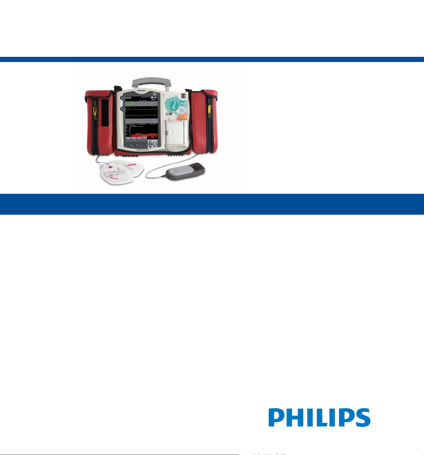
HeartStart MRx
M3535A/M3536A
Service Manual


Notice
About This Edition
Publication number 453564042441
Edition 3; Printed in the USA
The information in this document applies to the HeartStart MRx
versions indicated below. This information is subject to change
without notice.
Philips shall not be liable for errors contained herein or for
incidental or consequential damages in connection with the
furnishing, performance, or use of this material.
Edition History
Pub. Number Ed. S/W Version Print Date
1 A.00/A.01 Dec., 2003
2 A.02 June, 2004
M3535-90900
3 B.03 Nov., 2004
4 B.04 Jan., 2005
5 B.05 Oct., 2005
1 7.00 Sept., 2006
453564042441
2 9.00 Sept., 2007
3 F.01 Apr., 2010
Copyright
Copyright © 2003 – 2010
Koninklijke Philips Electronics N.V.
All rights are reserved. Permission is granted to copy and distribute
this document for your organization’s internal educational use.
Reproduction and/or distribution outside your organization in
whole or in part is prohibited without the prior written consent of
the copyright holder.
SMART Biphasic
Q-CPR™ is a trademark of Laerdal Medical. Nellcor
registered trademark of Nellcor Puritan Bennett, Inc. FilterLine
registered trademark and CapnoLine™
Medical Ltd. Rosetta-Lt™ is a trademark of General Devices.
The HeartStart MRx contains an Ezurio PC Card with Bluetooth®
wireless technology. The Bluetooth wordmark and logos are owned
by the Bluetooh SIG, Inc. and any use of such marks by Ezurio is
under license.
Other trademarks and trade names are those of their respective
owners.
®
is a registered trademark of Philips.
is a trademark of Oridion
®
is a
®
is a
Wa rn in g :
Radio frequency (RF) interference coming from devices other than
the HeartStart MRx may degrade the performance of the MRx.
Electromagnetic compatibility with surrounding devices should be
assessed prior to using the monitor/defibrillator.
Use of supplies or accessories other than those recommended by
Philips may compromise product performance.
Medical Device Directive
The HeartStart MRx complies with the requirements of the Medical
Device Directive 93/42/EEC and carries the
accordingly.
0123
mark
Manufacturer:
Philips Medical Systems
3000 Minuteman Road
Andover, MA USA 01810-1099
(978) 687-1501
Authorized EU-representative:
Philips Medizin Systeme Böblingen GmbH
Hewlett Packard Str. 2
71034 Böblingen
Germany
U.S. FCC and Industry Canada Radio Compliance:
Contains FCC ID: PQC-WMTS-MODULE
When using with IntelliVue Networking Option, operation of this
equipment requires the prior coordination with a frequency
coordinator designated by the FCC for the Wireless Medical
Telemetry Service. This device complies with Part 15 of the FCC
rules and RSS-210 of Industry Canada. Operation is subject to the
following conditions:
• This device may not cause harmful interference.
• This device must accept any interference received, including
interference that may cause undesired operation.
Any changes or modifications to this equipment not expressly
approved by Philips Medical Systems may cause harmful radio
frequency interference and void your authority to operate this
equipment.
Canada EMC: ICES-001
China: After-Sales Service: Beijing MEHECO-PHILIPS Medical
Equipment Service Center.
After-Sales Service Address: No. 208, 2nd District, Wang Jing Li Ze
Zhong Yuan, Chao Yang District, Beijing.
Postal code: 100102.
Telephone: 8008100038.
Registration number: SFDA(I)20083211481
Product Standard number: YZB/USA 1863-2008.
Chemical Content:
REACH requires Philips Healthcare to provide chemical content
information for Substances of Very High Concern (SVHC) if they
are present above 0.1% of the product weight. Components
of/within electric and electronic equipment may contain phthalates
above the threshold (e.g. bis(2-ethyl(hexyl)phthalate), CAS nr.:
117-81-7). The REACH SVHC list is updated on a regular basis.
Therefore, please refer to the following Philips REACH website for
the most up-to-date information on products containing SVHC
above the threshold:
http://www.philips.com/about/sustainability/reach.page
i

Conventions Used in This Manual
This book contains the following conventions:
WARNING: Warning statements describe conditions or actions that can result in personal injury or loss of life.
CAUTION: Caution statements describe conditions or actions that can result in damage to the equipment or loss of
data.
NOTE: Notes contain additional information on usage.
TIP: Tips provide hands-on insight into using or servicing this product.
The “bull’s eye” icon indicates a process or a procedure (a set of steps to achieve a certain goal)
Screen Text represents text that appear on the device screen, including the softkey labels.
Label Text or
Label Text represent other keywords.
On-line viewing only
Hypertext represents hypertext links, which will display as blue; click on the blue link to go
to that destination.
Click for quick access
Abbreviations
Name Abbreviation
Acute Cardiac Ischemia
Time-Insensitive Predictive Instrument
Batch LAN Data Transfer BLDT
Dial-Up Networking DUN
End-tidal carbon dioxide EtCO
File Transfer Protocol FTP
HeartStart MRx Monitor/Defibrillator HeartStart MRx;
Invasive Pressure IP
Invasive Pressure/Temperature IP/Temp
Non-invasive Blood Pressure NBP
Periodic Clinical Data Transmission PCDT
Pulse Oximetry SpO
Thrombolytic Predictive Instrument TPI
ACI-TIPI
, CO
2
device
2
2
ii

Contents
Chapter 1 Introduction 1
Who Should Use this Manual . . . . . . . . . . . . . . . . . . . . . . . . . . . . 1
How to Obtain Training . . . . . . . . . . . . . . . . . . . . . . . . . . . . . 1
Overview . . . . . . . . . . . . . . . . . . . . . . . . . . . . . . . . . . . 1
Features and Capabilities. . . . . . . . . . . . . . . . . . . . . . . . . . . . . . 2
Tour of the Device . . . . . . . . . . . . . . . . . . . . . . . . . . . . . . . . 3
General Service Information . . . . . . . . . . . . . . . . . . . . . . . . . . . . 6
Accessing Service Mode . . . . . . . . . . . . . . . . . . . . . . . . . . . . . . 8
Navigating in Service Mode. . . . . . . . . . . . . . . . . . . . . . . . . . . . . 10
Service Mode Functions . . . . . . . . . . . . . . . . . . . . . . . . . . . . . 10
Device Information . . . . . . . . . . . . . . . . . . . . . . . . . . . . . . 11
Other Resources . . . . . . . . . . . . . . . . . . . . . . . . . . . . . . . . . 12
Chapter 2 Maintenance 13
Introduction . . . . . . . . . . . . . . . . . . . . . . . . . . . . . . . . . . 13
HeartStart MRx Calibration Overview . . . . . . . . . . . . . . . . . . . . . . . . 13
NBP Module Calibration . . . . . . . . . . . . . . . . . . . . . . . . . . . . . 14
NBP Calibration Setup . . . . . . . . . . . . . . . . . . . . . . . . . . . . . 14
NBP Safety Features . . . . . . . . . . . . . . . . . . . . . . . . . . . . . . 15
NBP Calibration Procedure . . . . . . . . . . . . . . . . . . . . . . . . . . . 16
NBP Module Tests . . . . . . . . . . . . . . . . . . . . . . . . . . . . . . . . 17
Accuracy Test . . . . . . . . . . . . . . . . . . . . . . . . . . . . . . . . 17
Leakage Test . . . . . . . . . . . . . . . . . . . . . . . . . . . . . . . . . 17
Linearity Test . . . . . . . . . . . . . . . . . . . . . . . . . . . . . . . . 17
EtCO2 Module Calibration. . . . . . . . . . . . . . . . . . . . . . . . . . . . . 18
EtCO2 Calibration Equipment . . . . . . . . . . . . . . . . . . . . . . . . . . 18
EtCO2 Calibration Setup . . . . . . . . . . . . . . . . . . . . . . . . . . . . 18
EtCO2 Calibration Procedure . . . . . . . . . . . . . . . . . . . . . . . . . . . 21
EtCO2 Module Checks . . . . . . . . . . . . . . . . . . . . . . . . . . . . . . 23
EtCO2 Module Check Setup . . . . . . . . . . . . . . . . . . . . . . . . . . . 23
EtCO2 Status Display Check . . . . . . . . . . . . . . . . . . . . . . . . . . . 24
Ambient Pressure Check . . . . . . . . . . . . . . . . . . . . . . . . . . . . . 24
Leakage Check . . . . . . . . . . . . . . . . . . . . . . . . . . . . . . . . 24
Pump Check . . . . . . . . . . . . . . . . . . . . . . . . . . . . . . . . 26
Flow Rate Check . . . . . . . . . . . . . . . . . . . . . . . . . . . . . . . 26
Noise Check . . . . . . . . . . . . . . . . . . . . . . . . . . . . . . . . 26
Calibration Check . . . . . . . . . . . . . . . . . . . . . . . . . . . . . . . 27
iii

Table of Content
Chapter 3 Troubleshooting 29
Overview . . . . . . . . . . . . . . . . . . . . . . . . . . . . . . . . . . . 29
Troubleshooting Tools and Equipment . . . . . . . . . . . . . . . . . . . . . . . . 29
Obtaining Replacement Parts . . . . . . . . . . . . . . . . . . . . . . . . . . . 29
Ready For Use Indicator . . . . . . . . . . . . . . . . . . . . . . . . . . . . . 30
Automated Tests . . . . . . . . . . . . . . . . . . . . . . . . . . . . . . . . 31
Automated Test Summary . . . . . . . . . . . . . . . . . . . . . . . . . . . . 31
Weekly Shock Test and Operational Check. . . . . . . . . . . . . . . . . . . . . . . 33
Shift Check . . . . . . . . . . . . . . . . . . . . . . . . . . . . . . . . . 33
Weekly Shock Test . . . . . . . . . . . . . . . . . . . . . . . . . . . . . . 33
Operational Check . . . . . . . . . . . . . . . . . . . . . . . . . . . . . . 34
Service Mode Tests . . . . . . . . . . . . . . . . . . . . . . . . . . . . . . . 41
Configuration Password Management. . . . . . . . . . . . . . . . . . . . . . . . . 42
Troubleshooting Methodology . . . . . . . . . . . . . . . . . . . . . . . . . . . 42
Troubleshooting Flowcharts . . . . . . . . . . . . . . . . . . . . . . . . . . . . 44
M3538A Lithium Ion Battery Troubleshooting . . . . . . . . . . . . . . . . . . . . . 50
Faulty Batteries. . . . . . . . . . . . . . . . . . . . . . . . . . . . . . . . 50
Troubleshooting Tables . . . . . . . . . . . . . . . . . . . . . . . . . . . . . . 52
Audio Tones . . . . . . . . . . . . . . . . . . . . . . . . . . . . . . . . 53
Device Status Log Messages . . . . . . . . . . . . . . . . . . . . . . . . . . . 54
Access Log Messages . . . . . . . . . . . . . . . . . . . . . . . . . . . . . . 65
Startup Messages . . . . . . . . . . . . . . . . . . . . . . . . . . . . . . . 66
General Problems . . . . . . . . . . . . . . . . . . . . . . . . . . . . . . . 66
ECG Monitoring Problems . . . . . . . . . . . . . . . . . . . . . . . . . . . 67
NBP Monitoring Problems. . . . . . . . . . . . . . . . . . . . . . . . . . . . 68
SpO2 Monitoring Problems . . . . . . . . . . . . . . . . . . . . . . . . . . . 69
CO2 Monitoring Problems. . . . . . . . . . . . . . . . . . . . . . . . . . . . 70
Q-CPR Problems . . . . . . . . . . . . . . . . . . . . . . . . . . . . . . . 72
Defibrillation Problems . . . . . . . . . . . . . . . . . . . . . . . . . . . . . 74
Pacing Problems . . . . . . . . . . . . . . . . . . . . . . . . . . . . . . . 76
Display Problems . . . . . . . . . . . . . . . . . . . . . . . . . . . . . . . 76
Printing Problems . . . . . . . . . . . . . . . . . . . . . . . . . . . . . . . 77
Audio Problems . . . . . . . . . . . . . . . . . . . . . . . . . . . . . . . 78
Controls Problems . . . . . . . . . . . . . . . . . . . . . . . . . . . . . . 79
Internal Memory Problems . . . . . . . . . . . . . . . . . . . . . . . . . . . 79
External Data Card Problems . . . . . . . . . . . . . . . . . . . . . . . . . . . 80
iv

Table of Content
Chapter 4 Repair 81
Overview . . . . . . . . . . . . . . . . . . . . . . . . . . . . . . . . . . . 81
Who Should Perform Repairs . . . . . . . . . . . . . . . . . . . . . . . . . . . . 81
Repair Philosophy . . . . . . . . . . . . . . . . . . . . . . . . . . . . . . . . 81
Calling for Service . . . . . . . . . . . . . . . . . . . . . . . . . . . . . . . 82
Repair Notes . . . . . . . . . . . . . . . . . . . . . . . . . . . . . . . . . . 83
Safety Precautions . . . . . . . . . . . . . . . . . . . . . . . . . . . . . . . 83
Disposal . . . . . . . . . . . . . . . . . . . . . . . . . . . . . . . . . . 84
Repair Tools and Equipment . . . . . . . . . . . . . . . . . . . . . . . . . . . . 85
Key Components . . . . . . . . . . . . . . . . . . . . . . . . . . . . . . . . 85
External Assemblies. . . . . . . . . . . . . . . . . . . . . . . . . . . . . . . . 85
Bedrail Hook Mount . . . . . . . . . . . . . . . . . . . . . . . . . . . . . . 86
CPR Meter Rear Cover . . . . . . . . . . . . . . . . . . . . . . . . . . . . . 87
Handle and Cap Plate . . . . . . . . . . . . . . . . . . . . . . . . . . . . . 88
Labels . . . . . . . . . . . . . . . . . . . . . . . . . . . . . . . . . . . 91
Paddle Tray and Plates . . . . . . . . . . . . . . . . . . . . . . . . . . . . . 93
Paddle Tray 50-ohm Load Resistor . . . . . . . . . . . . . . . . . . . . . . . . . 95
Printer Assembly . . . . . . . . . . . . . . . . . . . . . . . . . . . . . . . 96
Therapy Cable Stabilizing Collar . . . . . . . . . . . . . . . . . . . . . . . . . . 98
Therapy Knob . . . . . . . . . . . . . . . . . . . . . . . . . . . . . . . 100
Top Assemblies . . . . . . . . . . . . . . . . . . . . . . . . . . . . . . . . 101
Bluetooth® Card . . . . . . . . . . . . . . . . . . . . . . . . . . . . . . 101
Internal Assemblies — Introduction . . . . . . . . . . . . . . . . . . . . . . . . 103
Opening the Case . . . . . . . . . . . . . . . . . . . . . . . . . . . . . . 103
Internal Assemblies — Front Case . . . . . . . . . . . . . . . . . . . . . . . . . 108
Overview of Front Case . . . . . . . . . . . . . . . . . . . . . . . . . . . . 108
PCMCIA Hole Plug . . . . . . . . . . . . . . . . . . . . . . . . . . . . . 109
Speaker and Microphone Assembly . . . . . . . . . . . . . . . . . . . . . . . . 110
Internal Memory Card . . . . . . . . . . . . . . . . . . . . . . . . . . . . 111
SpO2 PCA . . . . . . . . . . . . . . . . . . . . . . . . . . . . . . . . 112
Invasive Pressure/Temperature (IP/Temp) PCA . . . . . . . . . . . . . . . . . . . . 115
Measurement Module Panel . . . . . . . . . . . . . . . . . . . . . . . . . . 117
Therapy Switch . . . . . . . . . . . . . . . . . . . . . . . . . . . . . . 119
Fan Assembly . . . . . . . . . . . . . . . . . . . . . . . . . . . . . . . 120
Processor PCA . . . . . . . . . . . . . . . . . . . . . . . . . . . . . . . 121
Clock Battery . . . . . . . . . . . . . . . . . . . . . . . . . . . . . . . 128
Printer Connector PCA . . . . . . . . . . . . . . . . . . . . . . . . . . . . 129
Display Assembly . . . . . . . . . . . . . . . . . . . . . . . . . . . . . . 130
Ready For Use Indicator . . . . . . . . . . . . . . . . . . . . . . . . . . . . 132
Front Panel Buttons . . . . . . . . . . . . . . . . . . . . . . . . . . . . . 133
Front Case Assembly . . . . . . . . . . . . . . . . . . . . . . . . . . . . . 134
v

Table of Content
Chapter 4 Repair (Continued)
Internal Assemblies — Rear Case . . . . . . . . . . . . . . . . . . . . . . . . . .136
Overview of Rear Case . . . . . . . . . . . . . . . . . . . . . . . . . . . . . 136
Therapy Capacitor . . . . . . . . . . . . . . . . . . . . . . . . . . . . . . 137
Power PCA . . . . . . . . . . . . . . . . . . . . . . . . . . . . . . . . . 138
NBP and CO2 Module Tray . . . . . . . . . . . . . . . . . . . . . . . . . . . 141
Therapy PCA . . . . . . . . . . . . . . . . . . . . . . . . . . . . . . . . 143
Therapy Port . . . . . . . . . . . . . . . . . . . . . . . . . . . . . . . . 146
NBP Module . . . . . . . . . . . . . . . . . . . . . . . . . . . . . . . . 148
CO2 Module . . . . . . . . . . . . . . . . . . . . . . . . . . . . . . . . 149
CO2 Compartment Door . . . . . . . . . . . . . . . . . . . . . . . . . . . . 152
Battery Connector PCA . . . . . . . . . . . . . . . . . . . . . . . . . . . . 153
Rear Case Assembly . . . . . . . . . . . . . . . . . . . . . . . . . . . . . . 156
Closing the Case . . . . . . . . . . . . . . . . . . . . . . . . . . . . . . . . 158
Chapter 5 Networking and Data Transfer 161
Overview . . . . . . . . . . . . . . . . . . . . . . . . . . . . . . . . . . . 161
About the IntelliVue Networking Option . . . . . . . . . . . . . . . . . . . . . . . 161
About Periodic Clinical Data Transmission . . . . . . . . . . . . . . . . . . . . . . 162
About Batch LAN Data Transfer . . . . . . . . . . . . . . . . . . . . . . . . . . 162
IntelliVue Networking Option Installation . . . . . . . . . . . . . . . . . . . . . . . 163
Configuring the HeartStart MRx for IIC Connection . . . . . . . . . . . . . . . . . . 163
Connecting to the Network . . . . . . . . . . . . . . . . . . . . . . . . . . .163
Installation Verification . . . . . . . . . . . . . . . . . . . . . . . . . . . . . 167
Service . . . . . . . . . . . . . . . . . . . . . . . . . . . . . . . . . . . . 167
Service Menu . . . . . . . . . . . . . . . . . . . . . . . . . . . . . . . . 167
IntelliVue Network Troubleshooting . . . . . . . . . . . . . . . . . . . . . . . . 167
Periodic Clinical Data Transmission Troubleshooting . . . . . . . . . . . . . . . . . . . 176
Batch LAN Data Transfer Troubleshooting . . . . . . . . . . . . . . . . . . . . . . 178
WMTS Device Registration . . . . . . . . . . . . . . . . . . . . . . . . . . . . 180
Chapter 6 Performance Verification 181
Overview . . . . . . . . . . . . . . . . . . . . . . . . . . . . . . . . . . . 181
Required Testing Levels . . . . . . . . . . . . . . . . . . . . . . . . . . . . . . 181
Verification Test Equipment . . . . . . . . . . . . . . . . . . . . . . . . . . . . 183
Test and Inspection Matrix . . . . . . . . . . . . . . . . . . . . . . . . . . . . 184
Performance Verification Procedures . . . . . . . . . . . . . . . . . . . . . . . . . 188
Visual Inspection . . . . . . . . . . . . . . . . . . . . . . . . . . . . . . . 188
Service Mode Tests . . . . . . . . . . . . . . . . . . . . . . . . . . . . . . 189
Functional Checks . . . . . . . . . . . . . . . . . . . . . . . . . . . . . . 195
Safety Tests . . . . . . . . . . . . . . . . . . . . . . . . . . . . . . . . . 201
vi

Table of Content
Appendix A Parts and Accessories 203
Overview . . . . . . . . . . . . . . . . . . . . . . . . . . . . . . . . . . 203
Parts and Accessories Notes . . . . . . . . . . . . . . . . . . . . . . . . . . . . 203
Ordering Replacement Parts . . . . . . . . . . . . . . . . . . . . . . . . . . 203
Ordering Supplies and Accessories . . . . . . . . . . . . . . . . . . . . . . . . 203
Key Component Tracking . . . . . . . . . . . . . . . . . . . . . . . . . . . 204
Replacement Parts . . . . . . . . . . . . . . . . . . . . . . . . . . . . . . 204
Electrical Assemblies . . . . . . . . . . . . . . . . . . . . . . . . . . . . . . 205
Processor PCA and Software Support Tool . . . . . . . . . . . . . . . . . . . . . . 205
Other Replacement PCAs . . . . . . . . . . . . . . . . . . . . . . . . . . . 206
Other Electrical Assemblies . . . . . . . . . . . . . . . . . . . . . . . . . . . 206
Individual Electrical Parts . . . . . . . . . . . . . . . . . . . . . . . . . . . 207
External Electrical Components . . . . . . . . . . . . . . . . . . . . . . . . . 207
Internal Cables . . . . . . . . . . . . . . . . . . . . . . . . . . . . . . . 208
Paddles . . . . . . . . . . . . . . . . . . . . . . . . . . . . . . . . . 208
Mechanical Assemblies . . . . . . . . . . . . . . . . . . . . . . . . . . . . . 209
Replacement Mechanical Assemblies . . . . . . . . . . . . . . . . . . . . . . . . 209
Individual Mechanical Parts. . . . . . . . . . . . . . . . . . . . . . . . . . . 209
Labels. . . . . . . . . . . . . . . . . . . . . . . . . . . . . . . . . . . . 210
Instruction Label Sets . . . . . . . . . . . . . . . . . . . . . . . . . . . . . 210
Hazardous Shock Warning Label Set. . . . . . . . . . . . . . . . . . . . . . . . 211
Branding Label Set . . . . . . . . . . . . . . . . . . . . . . . . . . . . . . 211
Speaker Label Set . . . . . . . . . . . . . . . . . . . . . . . . . . . . . . 211
Connector Label Set . . . . . . . . . . . . . . . . . . . . . . . . . . . . . 211
Supplies and Accessories . . . . . . . . . . . . . . . . . . . . . . . . . . . . . 211
Key Components . . . . . . . . . . . . . . . . . . . . . . . . . . . . . . . 220
Appendix B Theory of Operation 223
Overview . . . . . . . . . . . . . . . . . . . . . . . . . . . . . . . . . . 223
Schematic Diagrams . . . . . . . . . . . . . . . . . . . . . . . . . . . . . . 224
System Level Interconnections . . . . . . . . . . . . . . . . . . . . . . . . . 224
Signal and Data Flow . . . . . . . . . . . . . . . . . . . . . . . . . . . . 225
ECG Signal Flow . . . . . . . . . . . . . . . . . . . . . . . . . . . . . . 226
Functional Descriptions . . . . . . . . . . . . . . . . . . . . . . . . . . . . . 227
Processor PCA . . . . . . . . . . . . . . . . . . . . . . . . . . . . . . . 227
Therapy PCA . . . . . . . . . . . . . . . . . . . . . . . . . . . . . . . 228
Power PCA . . . . . . . . . . . . . . . . . . . . . . . . . . . . . . . . 228
Battery Connector PCA . . . . . . . . . . . . . . . . . . . . . . . . . . . . 228
Power/Batteries . . . . . . . . . . . . . . . . . . . . . . . . . . . . . . . 228
Display Assembly . . . . . . . . . . . . . . . . . . . . . . . . . . . . . . 229
Indicators . . . . . . . . . . . . . . . . . . . . . . . . . . . . . . . . 229
RFU Indicator . . . . . . . . . . . . . . . . . . . . . . . . . . . . . . . 230
Front Panel Buttons . . . . . . . . . . . . . . . . . . . . . . . . . . . . . 230
Therapy Knob . . . . . . . . . . . . . . . . . . . . . . . . . . . . . . . 230
vii

Table of Content
Appendix B Theory of Operation (Continued)
Paddle Indicators and Controls . . . . . . . . . . . . . . . . . . . . . . . . . .230
Printer Assembly and PCA . . . . . . . . . . . . . . . . . . . . . . . . . . . .230
ECG Monitoring Functions . . . . . . . . . . . . . . . . . . . . . . . . . . . 231
Defibrillation . . . . . . . . . . . . . . . . . . . . . . . . . . . . . . . . 232
Transcutaneous Pacing . . . . . . . . . . . . . . . . . . . . . . . . . . . . . 233
Audio . . . . . . . . . . . . . . . . . . . . . . . . . . . . . . . . . . . 233
Data Storage . . . . . . . . . . . . . . . . . . . . . . . . . . . . . . . . 234
Clock Backup Battery . . . . . . . . . . . . . . . . . . . . . . . . . . . . . 234
NBP Module . . . . . . . . . . . . . . . . . . . . . . . . . . . . . . . . 234
IP/Temp PCA . . . . . . . . . . . . . . . . . . . . . . . . . . . . . . . . 234
SpO2 PCA . . . . . . . . . . . . . . . . . . . . . . . . . . . . . . . . . 235
CO2 Module . . . . . . . . . . . . . . . . . . . . . . . . . . . . . . . . 235
Bluetooth Card . . . . . . . . . . . . . . . . . . . . . . . . . . . . . . . 235
Q-CPR . . . . . . . . . . . . . . . . . . . . . . . . . . . . . . . . . . 235
Waveforms . . . . . . . . . . . . . . . . . . . . . . . . . . . . . . . . . . 236
Index 241
viii

Introduction
This Service Manual provides the information needed to successfully service the M3535A/M3536A
HeartStart MRx monitor/defibrillator. This manual provides you with information on troubleshooting,
repairing, and performance verification and safety testing of the monitor/defibrillator. There is also
information on the theory of operation, maintenance procedures, and ordering parts and supplies.
NOTE: This manual describes all optional features. If your HeartStart MRx does not have some of the optional
features listed in this manual, disregard the features, controls, and related information described in the
manual.
Who Should Use this Manual
The intended users of this manual are technical personnel who have been trained in the safe and proper
servicing of the HeartStart MRx.
1
How to Obtain Training
To assist in training, the Service Training DVD (453564044671) is available.
Philips IntelliVue Clinical Network Information Center (IIC), Patient Monitoring System, and
Telemetry System and other training is available through Philips Technical Education at
www.healthcare.philips.com/main/education/.
Overview
In this chapter, you will find general information that you should know before servicing the
HeartStart MRx. Detailed information regarding controls, operation, and capabilities of the device can
be found in the HeartStart MRx Instructions for Use that was shipped with the product and provides
information on setting up the device and regular maintenance procedures, such as performing
operational checks and battery maintenance. We recommend you review the HeartStart MRx Instructions
for Use before servicing this device. This Service Manual assumes you are familiar with the controls and
basic operations.
This chapter is organized into the following sections:
To p ic Page To p ic Page
Features and Capabilities
Tou r of th e De v ic e
2
3
Accessing Service Mode
Navigating in Service Mode
8
10
General Service Information
6
Other Resources
12
1

1: Introduction Features and Capabilities
Features and Capabilities
The HeartStart MRx is a lightweight, portable, monitor/defibrillator. It provides four modes of
operation: Monitor, Manual Defib, AED, and Pacer (optional).
In Monitor Mode you can monitor up to four ECG waveforms, acquired through a 3-, 5-, or 10-lead
ECG set or multifunction electrode pads. Optional monitoring of pulse oximetry (SpO
pressure (IP), non-invasive blood pressure (NBP), temperature (Temp), and carbon dioxide (EtCO
also available. Measurements from these parameters are presented on the display and alarms are available
to alert you to changes in the patient’s condition.
Monitor Mode also provides an optional 12-Lead ECG function, enabling you to preview, acquire, store,
transmit, and print 12-Lead ECG reports, with or without analysis/interpretation.
Manual Defib Mode offers simple, 3-step defibrillation. You analyze the patient’s ECG and, if
appropriate: 1) select an energy setting, 2) charge, and 3) deliver the shock. Defibrillation may be
performed using paddles or multifunction electrode pads. Manual Defib Mode also allows you to
perform synchronized cardioversion and internal defibrillation.
In AED Mode, the HeartStart MRx analyzes the patient’s ECG and determines whether a shock is
advised. Voice prompts guide you through the 3-step defibrillation process, providing easy-to-follow
instructions and patient information. Voice prompts are reinforced by messages that appear on the
display.
), invasive
2
) are
2
Both Manual Defib and AED Mode incorporate the Philips’ low energy SMART Biphasic waveform for
defibrillation, Q-CPR, and audio recording.
Optional Pacer Mode offers non-invasive transcutaneous pacing therapy. Pace pulses are delivered
through multifunction electrode pads, using a monophasic waveform.
The HeartStart MRx is powered by rechargeable lithium ion batteries. Available battery power is easily
determined by viewing the convenient battery power indicators located on the device display or by
checking the indicators on the battery itself. Additionally, an external AC or DC power supply may be
applied as a secondary power source and for continual battery charging.
The HeartStart MRx performs Automated Tests on a regular basis. The status of the device’s critical
functions are reported to the Ready For Use (RFU) indicator. Prominently displayed, the RFU indicator
communicates the status of your device, letting you know if it is operating correctly, needs attention, or is
unable to deliver therapy. In addition, performing the specified Operational Check ensures that the
HeartStart MRx is functioning properly.
The HeartStart MRx M3535 model with the IntelliVue Networking Option can connect to the Philips
IntelliVue Clinical Network.
The HeartStart MRx automatically stores critical event and trend data in its internal memory, such as
Event Summaries and 12-Lead Reports. The HeartStart MRx also enables you to copy data and event
information to an optional external data card for downloading to Philips’ data management solution,
HeartStart Event Review Pro, as well as transfer data using Bluetooth
transferred using Rosetta-Lt™.
The HeartStart MRx is highly configurable to better meet the needs of diverse users. Be sure to
familiarize yourself with the device’s configuration before using the HeartStart MRx.
®
Card. 12-Lead reports can also be
2
Tour of the Device 1: Introduction
Tour of the Device
This section gives an overview of the outside of the device.
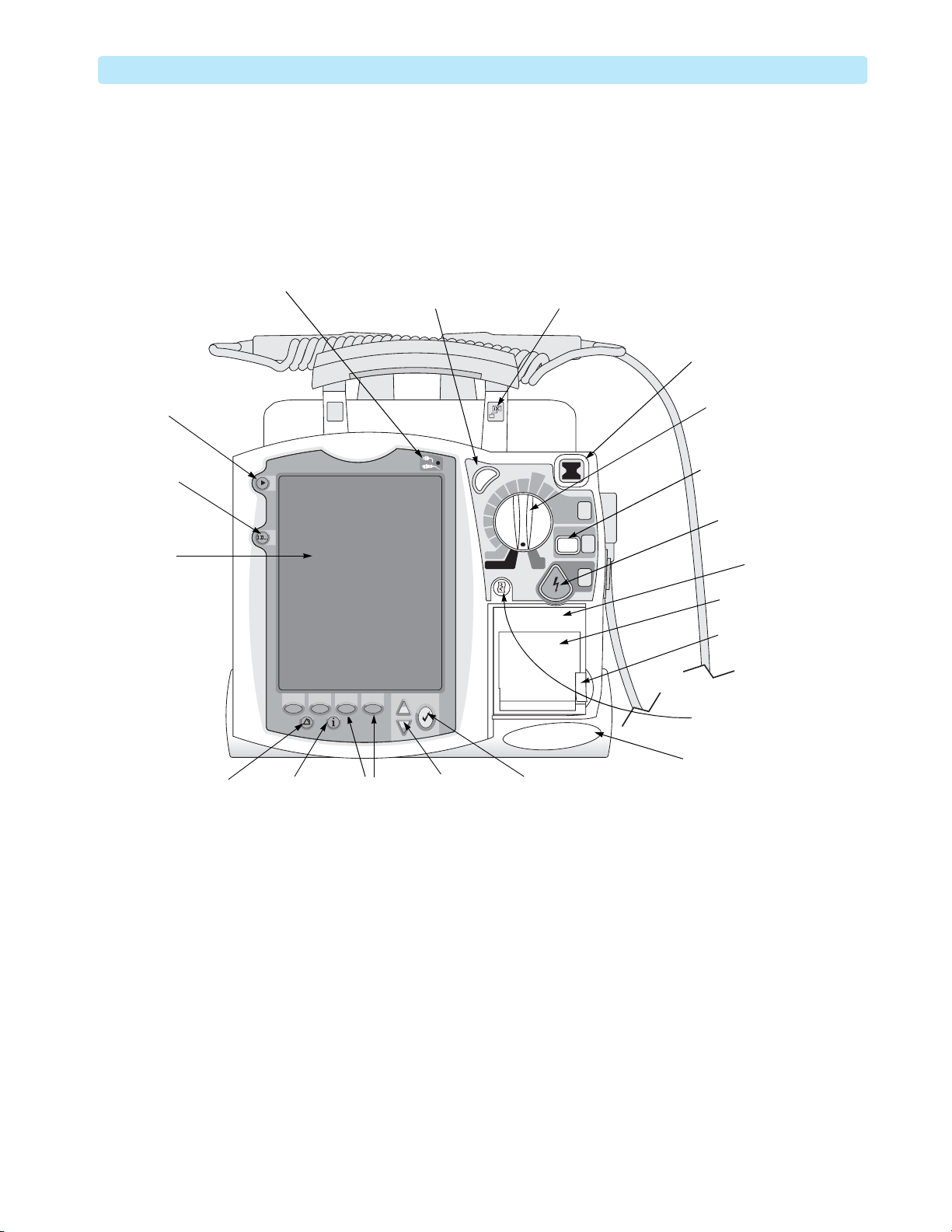
Front of the Device
Figure 1 Front View
Mark Event
button
Lead Select
button
Display
External Power
Indicator
Synchronized
Cardioversion (Sync)
button
Sync
b
b
70
e
e
D
D
l
l
a
a
50
u
u
n
n
a
a
30
M
M
20
15
1-10
Pacer
Monitor
Adult
Dose
120
150
100
170
On
On
O
AED
Network Ready
label (optional)
200
Select
Energy
1
Charge
2
Shock
3
Ready For Use
(RFU) Indicator
Therapy Knob
CHARGE button
SHOCK button
Printer
Printer door
Printer door
latch
Print button
Speaker
Alarm Pause
button
Event Summary
button
Softkeys
(4 total)
Navigation
buttons
Menu Select
button
3

1: Introduction Tour of the Device
Right Side
Figure 2 Right Side View
Left Side
Data Card
Therapy port
(behind connector)
Therapy
connector
Figure 3 Left Side View
CO2 Inlet port
CO2 Outlet port
Temp port
ECG Out
(Sync) jack
IP ports
2
CO
1
NBP port
2
™
m
a
e
r
t
s
o
r
c
i
M
G
EC
G
EC
ECG port
SpO
port
2
Measurement
Module Panel
4
Tour of the Device 1: Introduction
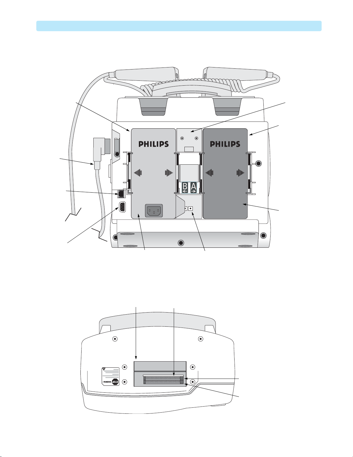
Rear Side
Figure 4 Rear Side View
Battery / AC /
Radio module
Compartment B
Therapy
Connector
and Cable
LAN
Connector
Bed Rail
Hook Mount
Battery
Compartment A
RS-232
Serial Port
Top Side
Figure 5 Top Side View
Top access panel
AC Power
Module
Battery
DC Power
Input
PCMCIA card slots
Bluetooth
card slot
Internal memory
card slot
5

1: Introduction General Service Information
General Service Information
Keep the following points in mind when servicing this product.
Installation
The HeartStart MRx does not require installation (for HeartStart MRx installation on the IntelliVue
Clinical Network, see “IntelliVue Networking Option Installation” on page 163). The HeartStart MRx
Instructions for Use describe the setup required before placing the device into service, as well as
configuration options. All setup activities are designed to be performed by personnel trained in the
proper operation of the product. To obtain a copy of the HeartStart MRx Instructions for Use and other
HeartStart MRx documentation in your local language visit:
follow links to Product Downloads —> Resuscitation —> M3535A/M3536A – Philips HeartStart MRx
—> Instructions for use.
Display Menus
To display a menu, press the Menu Select button. Then use the up or down Navigation
buttons to scroll through the available choices until the desired selection is highlighted. To activate the
selection, press the Menu Select button. Press
Exit to close the menu without activating a selection.
http://www.philips.com/ProductDocs and
Passwords
In order to access different modes within the monitor/defibrillator, a password is required. The passwords
are listed below:
• Service Mode: 27689
• Configuration Mode: 387466 (default password)
Upgrades
Upgrades are available to add specific functionality to the device after purchase. These upgrades are:
• M3530A SpO
• M3531A NBP
• M3532A EtCO
• M3533A Pacing
• M3534A 12-lead
Option B02: Acquisition
Option B04: 75-mm printer
Option B05: Asian 75-mm printer
• M3549A Wide bedrail hook
• M3801A 12-lead transmission (Bluetooth)
2
2
• M3802A 12-lead transmission (RS-232 and Bluetooth)
• M3806A Software
• M3808A Therapy PCA
• M4737A Display cover
• M4760A Handle and Cap Plate
• M4765A B-level Hardware, option B02
6

General Service Information 1: Introduction
• M4770A Q-CPR (with Compression Sensor)
• M4771A Q-CPR Data Capture
• M4772A Audio Recording
• M4773A 256 MB Data Card (internal and external)
NOTE: If your HeartStart MRx still has a smaller data card, then it is recommended to perform
this upgrade next time you perform an internal repair.
• M5527A External Paddles with tray
Option C01: Standard
Option C02: Water-resistant
• 861325 Event Summary, Bluetooth
• 861326 12-Lead Transmission, Rosetta-Lt interface (available in the USA only)
• 861356 IntelliVue Networking Option (wired, available for M3535A only)
• 861357 IntelliVue Networking Option (wired and wireless, available in the USA for M3535A only)
• 861359 Invasive Pressures
• 861360 Temperature
• 861442 ACI-TIPI & TPI
• 861443 Periodic Clinical Data Transmission (PCDT)
• 861444 Q-CPR (with CPR meter)
• 861447 Batch LAN Data Transfer (BLDT)
• 989803153411 Internal Bluetooth Card
Consult your sales representative, dealer, or distributor for the latest details. See “Ordering Supplies and
Accessories” on page 203.
Preventive Maintenance
Preventive maintenance and periodic operational checks are intended to be performed by the user. Both
topics are covered in the “Maintenance” chapter of the Instructions for Use.
The Maintenance chapter of this manual provides EtCO
Experienced and trained HeartStart MRx users (e.g. nurses and paramedics) may perform the calibration
using the NBP and EtCO
training material is included in the kits. Only qualified service personnel should perform the testing
procedures.
calibration kits (453564063841 and 453564063851 respectively). The
2
Repair Philosophy
Monitor/Defibrillator
The repair philosophy of the HeartStart MRx is subassembly replacement. Examples of subassemblies are
the printer, the Processor Printed Circuit Assembly (PCA), Therapy PCA, and selected connectors and
other items. Repairs that involve replacing components on a PCA are not supported.
and NBP calibration and testing procedures.
2
CAUTION: Individual component replacement should not be attempted. Component level repair is inadvisable due
to the extensive use of surface mount technology and the high parts-density on the circuit boards.
Unauthorized component replacement can impair performance of the HeartStart MRx.
7

1: Introduction Accessing Service Mode
WARNING: Remove all power sources (AC, battery, DC) before opening the device. Failure to do so may allow the
device to charge without warning and could result in serious injury or death.
Batteries
The M3538A Lithium-Ion battery is rechargeable. The battery periodically requires a calibration. At the
end of the battery’s useful life, it should be recycled or discarded according to local regulations and
replaced. Refer to the HeartStart MRx Instructions for Use for additional information.
For information on ordering replacements, see “Ordering Supplies and Accessories” on page 203.
WARNING: Never crush, penetrate, or attempt to open lithium-ion batteries. Never incinerate lithium-ion batteries.
High case temperatures resulting from abuse of the battery could cause physical injury. The electrolyte is
highly flammable. Rupture of the battery pack may cause venting and flame.
CAUTION: Due to their high energy density, lithium-ion batteries can deliver significant power. Use care when
working with or testing lithium-ion batteries. Do not short-circuit the terminals.
Accessing Service Mode
CAUTION: Be sure that the monitor/defibrillator is not connected to a patient when performing any function in
Service Mode.
NOTE: Make sure that you insert a battery charged to at least 20% into the device or connect external power
when you are performing functions in Service Mode.
To access Service Mode:
1 Turn the Therapy Knob to Monitor.
2 Press the Menu Select button to display the Main menu.
3 Select Other.
4 From the Other menu select Service.
The message appears:
Leaving Normal Operating Mode.
Patient Monitoring Is Off.
To Return To Normal Operating Mode, Press The Exit Softkey.
5 Press the Menu Select button to acknowledge the message.
You are prompted to enter a password.
6 Enter the password (27689) by scrolling through the list until the desired number is highlighted.
7 Press the Menu Select button to activate each selection.
8 Select Done when you have entered all of the numbers.
9 Press the Menu Select button to display the Service Mode Main menu, as shown in Figure 6.
8

Accessing Service Mode 1: Introduction
Figure 6 Service Mode Main Menu
Service
Cycle Counter :
Last
Calibration :
Exit
Service
- MAIN
02 Mar 2010 10:52
50,010
30 Jun 2006
09:42
Calibrate
B
A
Replacement recommended
Calibration
recommended
Service
Operational Check
Status Log
NBP
CO2
Controls
Display
Printer
CPR
Audio Recording
Instrument Telemetry
Device Info
Software Upgrade
9

1: Introduction Navigating in Service Mode
Navigating in Service Mode
Service Mode uses the same navigation controls as normal operating mode:
• To select a menu item, use the Navigation buttons to highlight your choice, then select that choice
by pressing the Menu Select button.
• To exit Service Mode and return to clinical mode, press the Exit Service softkey.
• To return to the Service Mode Main menu from any service screen press the Main Service softkey.
NOTE: The device’s default configuration settings are restored when you return to clinical mode after exiting
Service Mode.
Service Mode Functions
You can perform a variety of service-related activities from Service Mode, as follows:
• Run an Operational Check — “Operational Check” on page 34.
• View, print and clear the Device, Network, and PCDT Status logs — See “Device Status Log
Messages” on page 54.
• Perform maintenance on the NBP module — See “NBP Module Calibration” on page 14.
• Perform maintenance on the EtCO
• Run the Controls test — See “Controls Test” on page 190.
• Run the Display test (Version B.05 and greater) — See “Display Test” on page 191.
• Run the Printer test — See “Printer Test” on page 192.
• Run the CPR Test — See “CPR Meter and Compression Sensor Tests” on page 193.
• Run the Audio Recording Test — See “Audio Recording Test” on page 194.
• Install software and change the device’s language using the Software Support Tool — See “Installing
Software” on page 125.
• View information about the device, such as model number, serial number, options enabled on the
device, and the device’s language — See “Device Information” below. Use the Device Info menu to
enter the serial number and to enable options on the device after a Processor PCA repair. See
“Entering the Serial Number” on page 124 for more information.
NOTE: You can print detailed information on board and module levels through the Print Device Info option,
available in normal operating mode. See “Printing the Device Information” on page 11.
module — See “EtCO2 Module Calibration” on page 18.
2
10

Navigating in Service Mode 1: Introduction
Device Information
To view information about the device:
From the Service Mode Main menu, select Device Info.
Figure 7 Device Info Screen
Service
Model Number :
Serial Number :
Language :
Options :
- DEVICE INFO
02 Mar 2010 10:52
M3535A
US00100320
American English
SpO2, NBP, EtCO2, IBP, Temp,
12-Lead, 12-LTx Serial,
12-LTx Bluetooth, Pacing, Q-CPR,
vData, Audio Rec, 75mm Printer,
EventSum Bluetooth,
IntelliVue Net, Per Data Tx
A
B
Main
Service
MENU
Printing the Device Information
You can print detailed information on software versions, board and module levels, and internal memory
card capacity from the Print Device Info menu option. This option is available from the Other menu in
clinical modes.
To print the device information:
1 Be sure a battery charged to at least 20% is in place, or that external power is connected.
2 Turn the Therapy Knob to Monitor.
3 Press the Menu Select button to access the Main menu.
4 From the Main menu, select
Other.
5 From the Other menu, select Print Device Info.
Detailed information about the device is printed.
NOTE: Run an Operational Check after you have updated software, enabled an option, or performed a repair to
update the Device information.
11
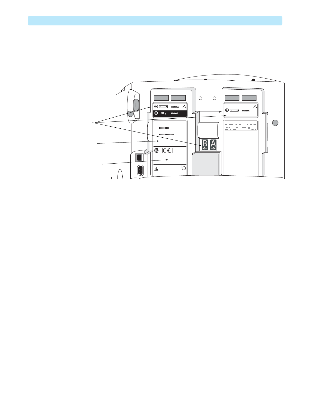
1: Introduction Other Resources
Hardware Version (Primary) Label
TheHeartStart MRx ships with a Hardware version label (also known as a Primary label) affixed to
battery compartment B, as shown in Figure 8.
Figure 8 Rear Case Labels
Generic labels
Hardware Version
(Primary) label
Hardware Version
Other Resources
For additional information on the HeartStart MRx, refer to the following Learning Products:
• HeartStart MRx Instructions for Use (989803160421)
•HeartStartMRx Service Training DVD (453564044671)
• M3538 Lithium Ion Battery Characteristics and Care Application Note (453564119661)
Other documentation can be found on the Philips website at:
B2
http://www.philips.com/ProductDocs.
12

Introduction
This chapter describes routine maintenance on the HeartStart MRx monitor/defibrillator.
Most routine maintenance, including periodic operational checks, paper replacement, lithium ion
battery maintenance and charge, etc. is performed by the user. Refer to the Instructions for Use for
detailed information on these maintenance procedures.
2
Maintenance
Service personnel are responsible for the following routine maintenance:
• Yearly calibration (or every 10,000 cycles) of the Non-invasive Blood Pressure (NBP) module.
•NBP module testing.
• Yearly calibration (or every 4000 hours) of the End-tidal Carbon Dioxide (EtCO
•EtCO
Click these links to access the maintenance procedures:
module checking.
2
To p ic Page Top i c Page
NBP Module Calibration 14
NBP Module Tests 17
EtCO2 Module Calibration 18
EtCO2 Module Checks 23
HeartStart MRx Calibration Overview
Consider reviewing the HeartStart MRx Calibration instructional video available online at
http://theonlinelearningcenter.com/schtml/mrx/calibration/.
Perform calibration when prompted by the CO2 Calibration Overdue and NBP Calibration
Overdue
code Fail/D (Versions B.05 and above) or Fail/NC (Versions prior to B.05).
Regardless of your configuration settings, millimeters of mercury are the unit of measure for pressure in
the HeartStart MRx calibration. Use the conversion formulae in Ta bl e 1 if necessary:
inops. If a calibration is overdue, then the HeartStart MRx Operational Check fails with the
Table 1 Units of Pressure Conversion
) module.2
2
1
1 unit = __ mmHg
1 kPa = 7.5 mmHg
1 mb
1 psi
1 atm.
1 inHg
1. The users may perform NBP calibration themselves if they obtain the NBP Calibration Kit, part # 453564063841.
2. The users may perform EtCO
.75 mmHg
=
51.7 mmHg
=
760 mmHg
=
25.4 mmHg
=
calibration themselves if they obtain the EtCO2 Calibration Kit, part # 453564063851.
2
13

2: Maintenance NBP Module Calibration
NBP Module Calibration
This section describes how to calibrate the HeartStart MRx NBP module.
To calibrate the HeartStart MRx NBP module you need:
• A manometer and cuff assembly or 500 ml expansion chamber. These instructions refer to the cuff
assembly, but can be used with the expansion chamber as well.
• A plastic container to wrap the cuff around.
Both the manometer/cuff assembly and plastic container are provided in the NBP Calibration Kit, part #
453564063841.
NBP Calibration Setup
To prepare for NBP calibration:
1 Access the Service Mode Main menu as described in “Accessing Service Mode” on page 8.
2 From the Service Mode Main menu, select NBP
.
3 The NBP Service screen is displayed (see Figure 9). You may hear a soft, high-pitch tone, this is
normal NBP pump operation.
Figure 9 NBP Service Screen
Service
Cycle Counter :
Last Calibration :
Pressure in
Cu ff :
- NBP
50,010
30 Jan 2010 09:42
0
02 Mar 2010 10:52
Replacement recommended
Calibration recommended
B
A
14
Main
Service
Calibrate
4 Check the Cycle Counter.
If the NBP module has executed more than 50,000 cycles, replacement is recommended.
Do not proceed with the calibration. Call for service.
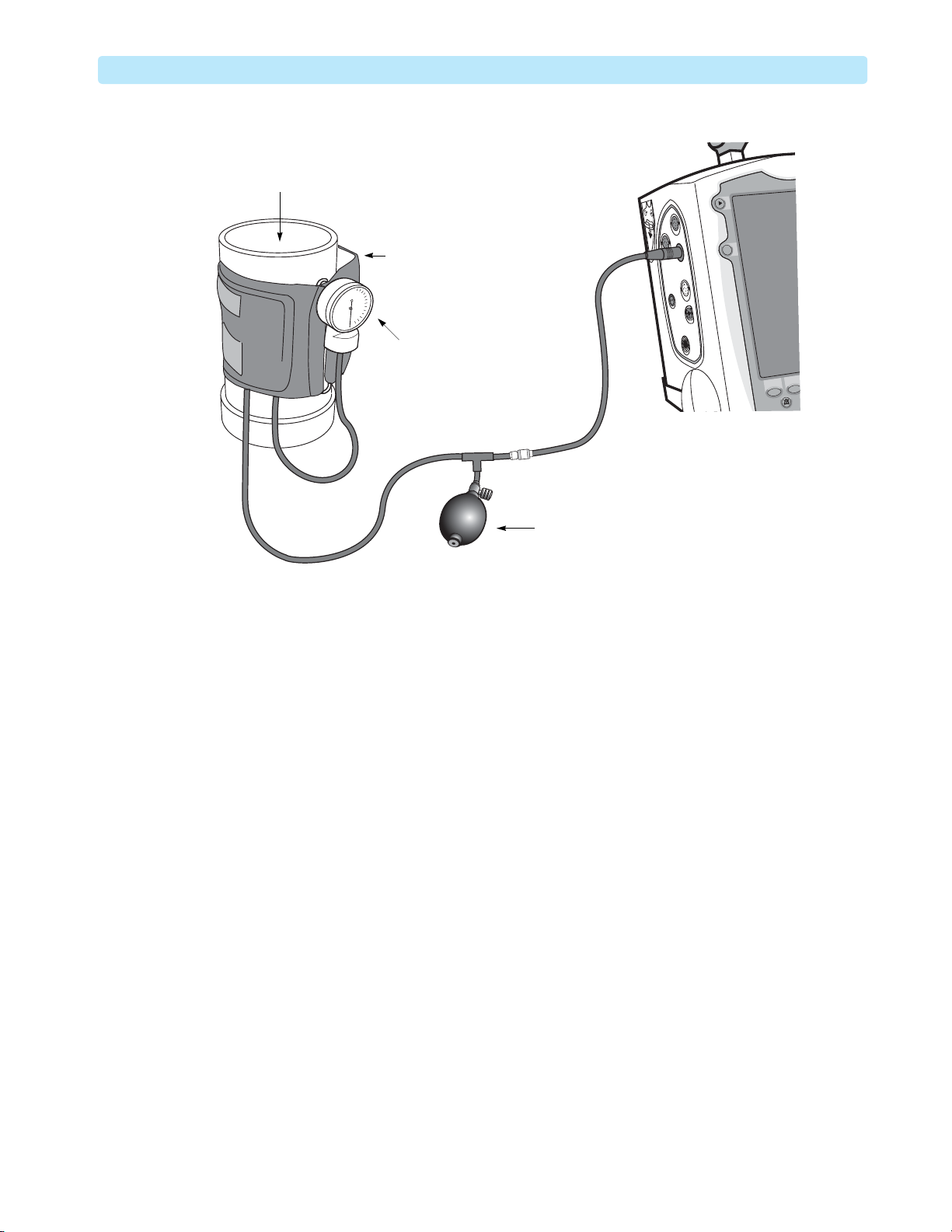
5 Connect the test cuff assembly to the NBP port and wrap the cuff around the container (see
Figure 10).
Do not overtighten the cuff. It should have space for about 500 mL of air. Leave room for two
fingers between the cuff and container before connecting the hook-and-loop fastener.
NBP Module Calibration 2: Maintenance
Figure 10 NBP Calibration Setup
Container
Loosely fitted
NBP cuff
Manometer
Pump
NBP Safety Features
The NBP module is equipped with the Timeout and Overpressure safety features that prevent injury to
the patient and damage to the device.
NBP Timeout
The NBP module times out when the pressure remains greater than 10 mmHg for 3 minutes. Do not
keep the cuff pressurized for more than 3 minutes during the calibration.
NBP Overpressure
The NBP module overpressure occurs when the cuff pressure reaches 300 mmHg. Do not raise the
pressure in the cuff to more than 280 mmHg during the calibration.
The safety features cause the valve to open and the pressure to drop.
To reset the module if a safety feature is triggered during calibration:
1 Press the
2 Access the NBP Service screen to restart the calibration.
Main Service softkey
15

2: Maintenance NBP Module Calibration
NBP Calibration Procedure
Complete the calibration process within three minutes to avoid the NBP module timeout.
To c a l i b ra t e N B P :
1 Press the
The message
2 Release all of the pressure in the cuff so that the manometer reads 0 mmHg.
3 Press the
The message
4 Increase the pressure so that the manometer reads 250 mmHg.
Take time to allow the pressure in the unit to equalize and stabilize. One way to do this is to
pressurize the cuff to 255 or 260 mmHg and wait for 30 seconds, then gently adjust the pressure
with the pump and valve.
5 When the pressure is stable at 250 mmHg, press the
6 Wait until the message
tests to check the results
NOTE: The message instructing you to perform the accuracy and leakage tests is for troubleshooting only
(see “NBP Module Tests” on page 17). These tests are not performed as part of calibration.
7 After several seconds the message clears, and the NBP Service screen is displayed. Release the
pressure in the cuff to avoid the safety timeout.
8 Run an operational check to update the calibration status. See the “Troubleshooting” chapter of
HeartStart MRx Service Manual for guidance.
Calibrate softkey.
Apply 0 mmHg. Select Next when ready is displayed.
Next softkey.
Apply 250 mmHg. Select Next when ready is displayed.
Next softkey again.
Calibration complete. Please perform the accuracy and leakage
is displayed.
NBP Calibration Failure
If the error message Calibration failed. Check that the pressure applied is correct. Please
restart calibration
1 Recheck the manometer and cuff assembly connections.
2 Loosen the cuff. If less than ten pump compressions fill the cuff, then it is too tight.
3 Press the
4 Select NBP from the Service Main Menu.
5 Restart the “NBP Calibration Procedure” on page 16, making sure that the applied pressures are
correct.
6 Call for service if you cannot successfully complete the calibration.
appears at any moment during NBP calibration, then:
Main Service softkey.
16

NBP Module Tests 2: Maintenance
NBP Module Tests
Perform NBP Module Tests only if there is an uncertainty about the module performance.
Each of the procedures assumes the monitor/defibrillator, the manometer, and the cuff assembly are still
set up as they were at the end of the previous test.
If all results are as described, the device passes that portion of the test. Return to the Service Mode Main
menu by pressing the
If there is any failure, begin troubleshooting and repairing the device as needed. See “Troubleshooting”
on page 29.
Accuracy Test
To test the NBP Module accuracy:
1 Connect the NBP tubing to the NBP port on the monitor/defibrillator, and connect the test
manometer and cuff to the tubing. See Figure 10 “NBP Calibration Setup” on page 15.
2 Pressurize the cuff to approximately 250 mmHg.
3 Wait for 30 seconds to allow the pressure in the unit to equalize.
4 When the pressure stabilizes, compare the displayed pressure reading to the pressure indicated by the
manometer.
Main Service softkey.
5 If the difference between the manometer and the displayed pressure is more than 2 mmHg, calibrate
the NBP module as described in “NBP Module Calibration” on page 14 and repeat the test.
6 Release the pressure in the cuff before proceeding to the next test to avoid the safety timeout.
Leakage Test
To test the NBP Module for leaks:
1 Pressurize the cuff to approximately 250 mmHg.
2 Wait for 30 seconds to allow the pressure in the unit to equalize.
3 Watch the displayed pressure for 60 seconds.
4 Record the pressure drop at the end of 60 seconds.
5 If the pressure decreases by more than 6 mmHg, there is a leak. Replace the tubing and cuff assembly
and try the leakage test again. If the pressure still decreases by more than 6 mmHg, begin
troubleshooting and repairing the device as needed.
6 Release the pressure in the cuff before proceeding to the next test to avoid the safety timeout.
Linearity Test
To test the NBP Module linearity:
1 Pressurize the expansion chamber to approximately 150 mmHg.
2 When the pressure is stabilized, compare the displayed pressure reading to the pressure indicated by
the manometer.
3 If the difference between the manometer and the displayed pressure is more than 2 mmHg, calibrate
the NBP module as described in “NBP Module Calibration” on page 14 and repeat the test.
17
2: Maintenance EtCO2 Module Calibration
EtCO2 Module Calibration
This section describes how to calibrate the HeartStart MRx EtCO2 (sometimes called CO2) module.
EtCO2 Calibration Equipment
To calibrate the HeartStart MRx EtCO2 module you need:
•Gas flow valve
• Modified Filterline set with T-shaped tubing assembly
• 5% calibration gas cylinder (15210-64010, six cans per case)
•Calculator
• Barometer to measure ambient pressure or other means of determining the ambient pressure.
Both the gas flow valve and Modified Filterline are provided in the CO
# 453564063851. The CO
troubleshooting only (see “EtCO
Calibration Kit, also contains a flow tube and two air plugs that are used for
2
Module Checks” on page 23) and not used in calibration.
2
EtCO2 Calibration Setup
To prepare for the calibration:
1 Access the Service Mode Main menu as described in “Accessing Service Mode” of the Introduction
chapter of HeartStart MRx Service Manual.
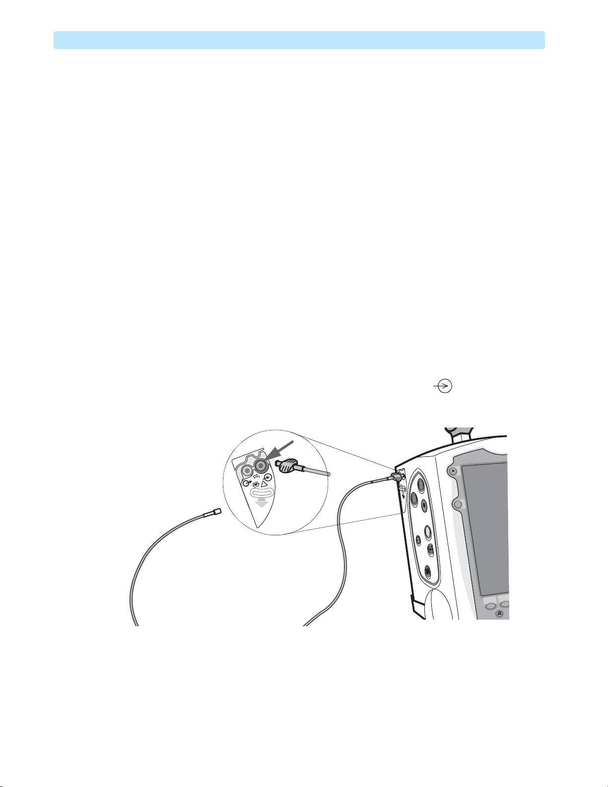
2 Connect the Modified FilterLine from the kit to the CO
Figure 11 CO2 Preparation Setup
!
Modified FilterLine
Calibration Kit, part
2
inlet marked . See Figure 11.
2
18
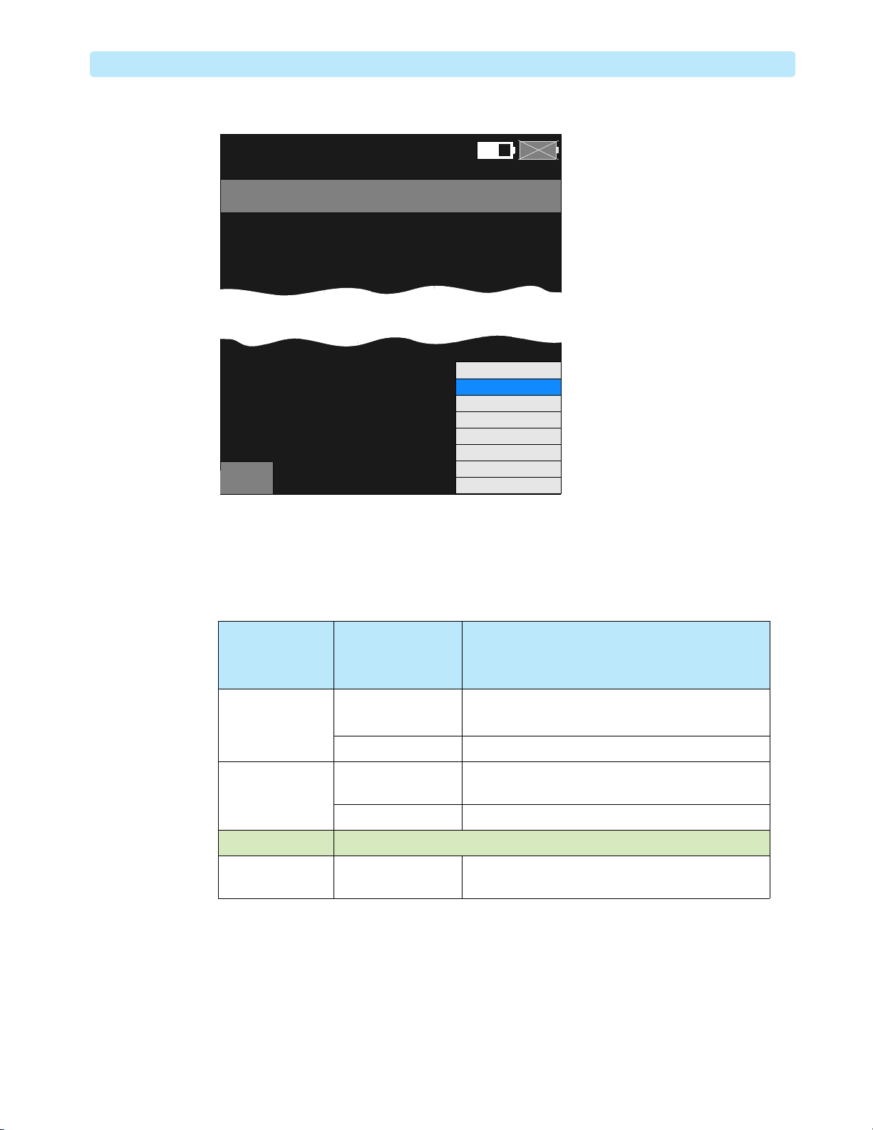
3 From the Service Mode Main menu, select
After a few seconds delay, the CO
Service screen is displayed, as shown in Figure 12.
2
CO2.
EtCO2 Module Calibration 2: Maintenance
Figure 12 CO2 Service Screen
Service
CO2 Operating Hours :
Last Calibration :
Ambient Pressure :
Cell Pressure :
Main
Service
- CO2
02 Mar 2010 10:52
15,004 hours
30 Jan 2010 09:42
760 mmHg
733 mmHg
Replacement recommended
Calibration recommended
CO2
Ambient Pressure
Leakage Check
Pump Check
Flow Rate Check
Noise Check
Calibration Check
B
A
Exit
You may hear a soft, low-pitch tone, this is normal EtCO2 pump operation. Another indication of
the EtCO
pump activity is the difference between the Ambient and Cell pressures. Subtract the Cell
2
pressure from the Ambient pressure and consult Figure 2 to interpret the difference.
Table 2 Modified FilterLine Connection Checking and Troubleshooting
Ambient
Pos sib le Cause Suggested Solution
Pressure
– Cell Pressure
0Bad connection 1 Reconnect the Modified FilterLine.
2 Go back to Main Service and reselect EtCO
Pump malfunction Call for service.
9 mmHg or less Modified FilterLine is
Replace the Modified FilterLine.
broken
Pump malfunction Call for service.
10 - 30 mmHg The pump is operating normally, and the sensor is warming up.
31 mmHg or more Modified FilterLine is
blocked
4 Older models of the EtCO
sensor must warm up for at least 20 minutes before the calibration.
2
Check that the Modified FilterLine is not kinked and
free of blockages. Replace if necessary.
a Check Device Info.
b If EtCO
Module SW version is 01.xx, then warm up the sensor before calibration. Note the
2
warm-up time. You can use the HeartStart MRx screen clock. Do not start calibration until the
EtCO
sensor has been warmed up. Continue the preparation.
2
c If EtCO
Module SW version is 02.xx or above, then proceed with calibration without waiting
2
for warm-up.
.
2
19

2: Maintenance EtCO2 Module Calibration
5 Check the CO2 Operating Hours.
If the CO
module has clocked more than 15,000 hours, replacement is recommended.
2
Do not proceed with the calibration. Call for service.
6 Obtain a reliable measurement of local atmospheric pressure by using a barometer or by getting the
local atmospheric pressure data from the Internet, local airport, or weather station located at the
same altitude as your HeartStart MRx.
7 Press the Menu Select button and select Ambient Pressure.
8 Using and buttons, adjust the HeartStart MRx’s Ambient Pressure setting to the
measurement obtained in Step 6.
9 Press the Menu Select button again to accept the adjusted Ambient Pressure value.
10 Calculate the expected CO
The expected CO
reading depends on both the gas concentration you are using (5.0%) and the
2
reading.
2
ambient pressure. Calculate as follows:
a
Cal. Gas Concentration × ambient pressure = Expected
CO
value
2
For example:
[0.05] × [760 mmHg] = 38 mmHg
b Calculate the allowable tolerance, which is ± 5% of the expected reading. Calculate as follows:
[±0.05] × Expected
CO
value= ± tolerance (mmHg)
2
For example:
[±0.05] × 38 = ± 1.9 (mmHg)
In this example, the displayed reading is expected to be 38 ± 1.9 mmHg.
c Round to the nearest whole number because HeartStart MRx does not show fractions. The
expected CO
d Save your calculations. You will compare the numbers with the actual CO
reading in our case should be between 36 and 40 mmHg.
2
sensor reading
2
during the calibration validation.
11 Fit the 5% CO
gas cylinder with the valve. Screw the valve on tightly.
2
12 Watch the manometer on the valve.
While the gas pressure does not have to be high for successful calibration, it should be present.
13 Connect the soft tubing at one end of the modified Filterline to the gas valve outlet, and leave the
other end open to atmosphere. See Figure 13.
20
 Loading...