

Page 1

SYNTIA
SERVICE
MANUAL
Revision 02 December 2012
All parts of this document are the property of Saeco International Group.
All rights reserved. This document and all the information herein is provided without liability deriving
from any errors or omissions. Furthermore, no part may be reproduced, used or collected, except where
express authorisation has been provided in writing or through a contractual agreement.
Page 2

Page
1. Introduction
1.1 Documentation required 1
1.2 Tools and equipment required 1
1.3 Material 1
1.4 Safety warnings 1
1.5 Service Policy 2
1.6.1 External machine parts 3
1.6.2 Internal machine parts 4
2. Technical specifi cations
2.1 Technical specifi cations 1
2.2 Specifi cation for the measurement of the coffee
products temperature 2
2.2 Machine parameters and performance 3
3. Brief instructions Rev.01
3.1.1 Customer menu and Digital programming 1
3.1.2 Customer menu and Focus programming 5
3.2 Operation, cleaning and maintenance 7
4. Operating logic
4.1. Water circuit 1
4.2 Control ringnut and valve 2
4.3 Coffee cycle operating diagram 3
4.4 Single microswitch 4
4.5 Temperature sensor 4
4.6 Coffee grinder operation 5
4.7 Low bean level detection, dose quantity
adjustment, coffee grinder blocked 5
4.8 Dose self-learning 6
Table of contents
Saeco International Group SYNTIA
Page 3

Table of contents
Page
5. Service mode Rev.01
5.1.1 Digital test mode 1
5.1.2 Focus test mode 5
5.2. Error codes 7
6. Service & Maintenance
6.1 Repair schedule 1
6.2 Service schedule 1
6.3 Final test 2
7. Disassembly Rev.01
7.1 Outer elements disassembly 1
7.2 Coffee spout disassembly 2
7.3.1 Disassembling keypad card and Digital control knob 3
7.3.2 Disassembling keypad card and Focus control knob 3
7.4 Power/CPU card disassembly 4
7.5 Gearmotor disassembly 4
7.6 Boiler disassembly 5
7.7 Valve disassembly 5
7.8 Pump and turbine disassembly 6
7.9 OETIKER clamps assembly and disassembly 7
7.10 Coffee grinder disassembly 8
7.11 Grinder adjustment / assembly and disassembly 9
8. Notes
9. Water circuit diagram
9.1. Water circuit diagram
10. Electrical diagram
10.1 Digital wiring diagram
10.2 Focus wiring diagram
Saeco International Group SYNTIA
Page 4

Saeco International Group SYNTIA
CHAPTER 1
INTRODUCTION
Page 5
SYNTIA 01 INTRODUCTION
Saeco International Group Page 1 / 04
1.1 Documentation required
The following documentation is needed for repair procedures:
• Instruction booklet for specifi c model
• Technical documentation for specifi c model (diagrams, exploded view, sympton cure and
service manual)
1.2 Tools and resources
As well as the standard equipment, the following is required:
Qty. Description Notes
1 Screwdriver Torx T 10
1 Pliers for Oetiker clamps
1 CC -A - Vdc tester
1 Digital thermometer Scale limit > 150°C
1 SSC (Saeco Service Center) Programmer
1.3 Material
Description Notes
Thermal paste Heating element > 200°C
Descaler Saeco Entkalker
Grease solvent Personal preference
Silicone grease Safe to use with food
1.4 Safety warnings
We recommend you consult this Service Manual of the machine before performing any maintenance work.
Observe all applicable standards relating to the repair of electrical appliances.
Always disconnect the power plug from the mains before beginning repair work.
Simply turning off the main machine power switch is not an adequate safety precaution.
This appliance is rated as protection class I.
Insulation and dielectric rigidity tests must be performed on completion of any repair.
Page 6
SYNTIA 01 INTRODUCTION
Saeco International Group Page 2 / 04
Components Assembly use Single components available
COFFEE
GRINDER
Only for OOW repairs
YES, to consult the specifi c exploded-view of the
machine or of the Coffee Grinder on website
BREWING
UNIT
Only for OOW repairs
YES, to consult the specifi c exploded-view of the
machine or of the Brewing unit on website
BOILER Only for OOW repairs
YES, to consult the specifi c exploded-view of the
machine on website
GEAR
MOTOR
Only for OOW repairs
YES, to consult the specifi c exploded-view of the
machine on website
FILTER
HOLDER
Only for OOW repairs
YES, to consult the specifi c exploded-view of the
machine on website
MILK
CARAFE
Only for OOW repairs
YES, to consult the specifi c exploded-view of the
machine on website
THERMAL
CARAFE
Only for OOW repairs
YES, to consult the specifi c exploded-view of the
Thermal Carafe on website
MILK ISLAND Only for OOW repairs
YES, to consult the specifi c exploded-view of the
Milk Island on website
List of principal assembly present in all our coffee machines
1.5 Service POLICY grid as used for coffee machine
For IN WARRANTY repairs is mandatory to use the single components (not the assembly) avail-
able in the exploded views of the coffee machines or of the specifi c components. If you fi nd the
information “SEE THE EXPLODED VIEW E........” in the assembly description fi eld, it means that
the single components of the assembly are available in the other pages of the exploded view. It’s
possible to use the assembly only if there is a specifi c Symptom Cure that include this possibility
or when the single components are not available for the order.
Page 7
SYNTIA 01 INTRODUCTION
Saeco International Group Page 3 / 04
1.6.1 External machine parts
03
Grinding adjustment
knob
Pre-ground coffee
compartment
Coffee bean container
cover
Cup rack
Grounds
drawer
Service hatch
Brew group
Drip tray full indicator
Dispensing pipe
protection
Hot water/steam
dispensing pipe
drip tray
Water tank
Control
panel
Coffee
dispenser
coffee bean containeri
Main on/off
switch
Power cord
Selector
Coffee/hot water/steam
Long coffee
luminous button
LED display
F O C U S
Long coffee
luminous button
Aroma/pre-ground
coffee key
ON/OFF button
Selector
Coffee/hot water/steam
LCD display
D G T
Aroma/pre-ground
coffee key
Strong coffee
dispensing button
Long coffee
dispensing button
Page 8
SYNTIA 01 INTRODUCTION
Saeco International Group Page 4 / 04
1.6.2 Internal machine parts
Boiler insulation
and boiler
Coffee grinder
Side door
microswitch
Coffee grinder motor
PWR/CPU
card
Temperature sensor
Pump
Water level sensor
Page 9

Saeco International Group SYNTIA
CHAPTER 2
TECHNICAL
SPECIFICATIONS
Page 10
SYNTIA 02 TECHNICAL SPECIFICATIONS
Saeco International Group Page / 04
2.1. Technical specifi cations
Power supply and output: 240 V~ 50 Hz 1400 W - 230 V~ 50/60 Hz 1400 W -
120 V~ 60 Hz 1500 W - 100 V~ 50/60 Hz 1300 W
Temperature monitoring: Variable resistor sensor (NTC) - transmits the value to the
electronic P.C.B
Safety system: 2 manual reset or one-shot thermostats (175°C)
Coffee heat exchanger output:
Stainless steel
(230/120 V~) 1300 W – (100 V~) 1100W
for coffee, hot water and steam dispensing
Gear motor: 33VC with 2 rotation directions; power supply 24VC
Pump: Ulka with reciprocating piston and 120°C cutout 48 W, 230V,
50 Hz, Type EP5 approx. 13-15 bar 120V, 60Hz 100V, 50/60 Hz
Overpressure valve: Opens at approx. 16-18 bar
Water fi lter: In tank
Coffee grinder: Direct current motor with fl at ceramic grinders
Hot water/steam valve Presblock
Automatic dosage Dose adjustment controlled by the electronic system
Power consumption: During the heating phase - approx. 5.6 A
Dimensions: W x H x D in mm: 256x315x410
Weight: 9 kg
Water tank capacity: 1l.
Coffee container capacity 200 gr. coffee beans
Dregs drawer capacity 8
Heat exchanger capacity: Approx. 10 cc
Water circuit fi lling time: Approx. 15 seconds for fi rst fi lling cycle
Heating time: Approx. 45 seconds.
Grinding time: Approx. 8-10 seconds.
01
Page 11

SYNTIA 02 TECHNICAL SPECIFICATIONS
Saeco International Group Page / 04
2.2. Specifi cation for the measurement of the coffee products temperature.
The temperature is infl uenced by the fl ow from the dispenser and stratifi cation of temperatures in
the glass. In order to consider these phenomena and to introduce measures that allow comparisons in controlled conditions, below guidelines must be followed:
Conditions:
a) Water temperature in tank: 23°C (+/-2°C).
b) It must be used a plastic cup (see picture N°1).
c) It must be used a thermocouple thermometer (e.g. type K - see picture N°2).
d) The coffee machine is tested without any change of parameters or calibrations, which may
affect the temperature of products, so the measurement of temperature must be done with
machine in default factory setting.
Procedure:
1. The temperature must be measured in the cup, immediately after dispensing. Cup has to be
placed on a non-metal surface using a thermocouple thermometer.
2. The temperature in the cup is measured by immersing the probe of the thermometer up to
touch the bottom.The probe then must be moved in a circular motion for 5/6 rotations. At the
of the rotations, stop in the center of the cup.
3. The highest temperature measured during the rotations is the value we are searching for, and
that must be reported;
4. Test measurement: from end of dispensing to the end of rotations must be completed within 12
seconds.
Limits of acceptability
The acceptance limits are divided by features and products and are the following:
Espresso Coffee Italy Q.ty 25/40 gr.
Temperature of 1st product 69°C ≤ 85°C
Temperature of 2nd product 72°C ≤ 85°C
Coffee Q.ty 70/120 gr.
Temperature of 1st product 69°C ≤ 85°C
Temperature of 2nd product 72°C ≤ 85°C
Picture 1
Picture 2
Page 12
SYNTIA 02 TECHNICAL SPECIFICATIONS
Saeco International Group Page / 04
RINSE Initial rinse Final rinse
When performed At coffee machine activation
when the boiler temperature is
≤ 50°C
When the machine is switched
off electronically, manually or
automatically after 60', if at least
one coffee has been dispensed,
before switching off
No. of pulses 180 80
Stopping option Yes, by pressing any key Yes, by pressing any key
User disable option No No
Production/Service
department disable option
No No
No. of pulses user
adjustment option
No No
No. of pulses Production/
Service department
adjustment option
No No
Pulse range (Min - Max) No No
WATER HARDNESS CANNOT BE SET
DREGS DRAWER Description and values
Time-out for dregs drawer 5 sec.
Empty dregs drawer alarm after
(double coffee is the last product dispensed)
8 lots of dregs
(9 lots of dregs)
Warning to empty dregs drawer after No
Reset dregs counter Every time the dregs drawer is removed for at
least 5 seconds, even if the "empty dregs" alarm
has not been activated
03
2.3. Machine parameters and performance
PRODUCT
QUANTITY
Minimum
amount
(Puls.)
Default
amount
(Puls.)
Maximum
amount
(Puls.)
Programm.
by the user
Programm. by
Production / Service
Espresso 70 165 600 Yes No
Medium
coffee
No No No No No
Long coffee 70 440 600 Yes No
Pre-ground Yes
Hot water Continues until the water supply has been exhausted (capacitive sensor)
Steam for
frother
Continues until the water supply has been exhausted (capacitive sensor)
Page 13
SYNTIA 02 TECHNICAL SPECIFICATIONS
Saeco International Group Page / 04
POWER/OFF Description and values
Inlet time (min. – max.) 60 minutes
Inlet time (default) No
Inlet time prog. by the user No
Inlet time prog. by Production/Service department No
WATER TANK Description
Level sensor Yes
Water reserve (pulses) with water fi lter 200
Water reserve (pulses) with no water fi lter 200
Water reserve modifi able by Production/Service departments No
"Fill tank" alarm Yes
"No tray" alarm No
Water mains No
04
Page 14

Saeco International Group SYNTIA
CHAPTER 3
BRIEF INSTRUCTIONS
Rev.01 February 2010
Page 15
SYNTIA 03 BRIEF INSTRUCTIONS
Saeco International Group Page 1 / 07
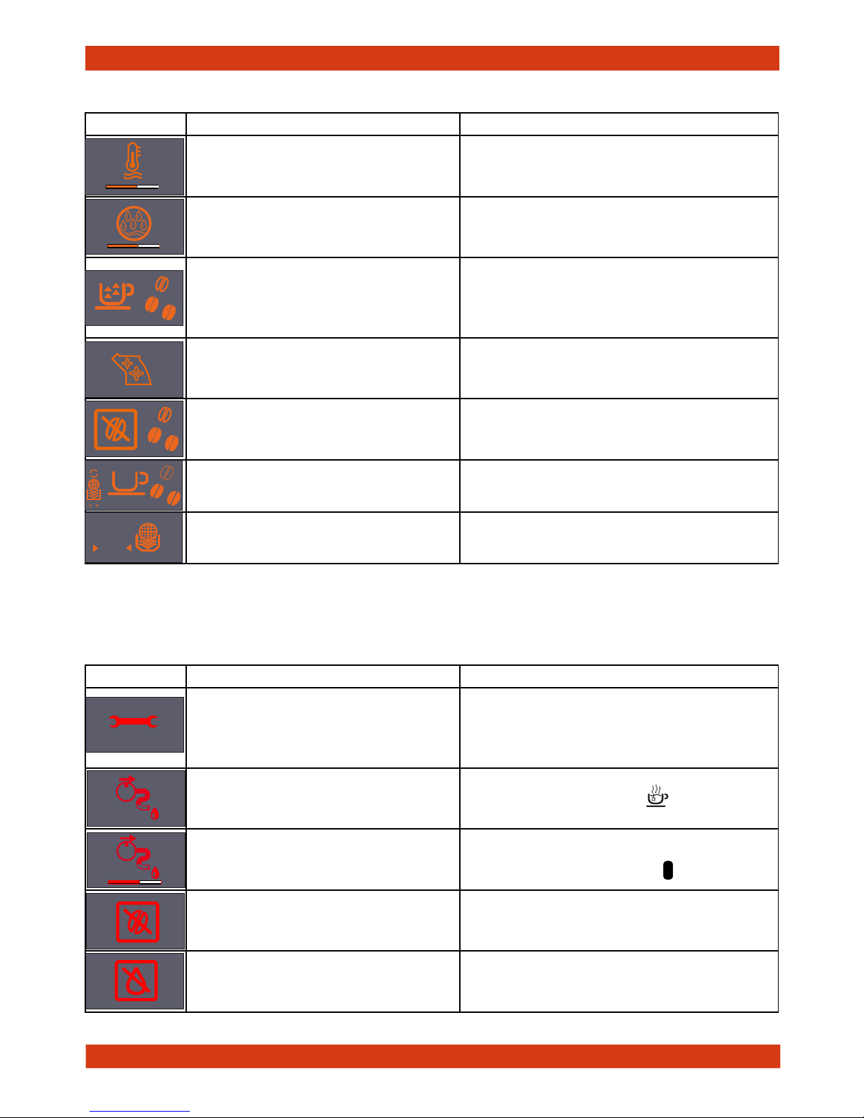
3.1. Customer and programming menu
Indications Causes Solutions
Machine at correct temperature
- for coffee bean dispensing
- for hot water dispensing
Proceed with the dispensing process
Machine at correct temperature
- for pre-ground coffee dispensing
Proceed with the dispensing process
Machine dispensing steam Proceed with steam dispensing
Machine dispensing hot water Proceed with hot water dispensing
Machine dispensing one coffee
Wait for the dispensing process to end
(dispensing stops when you press the
key again)
Machine dispensing two coffees
Wait for the dispensing process to end
(dispensing stops when you press the
key again)
The machine is being programmed
with the coffee cup fi ll level
Stop dispensing as desired
MEMO
Machine ready signals (GREEN)
Page 16
SYNTIA 03 BRIEF INSTRUCTIONS
Saeco International Group Page 2 / 07
OK
-
Indications Causes Solutions
Machine in pre-heating phase
for coffee, hot water and steam
dispensing.
Wait until heated
(see bar)
The appliance is rinsing - wait until
end of operation Wait until end of operation
The appliance requires a descaling
cycle
Perform the descaling cycle
To enter the descaling cycle press the
aroma/pre-ground coffee key for 5
sec.
Brewing unit resetting during
appliance reset
Wait for reset
Fill the coffee bean container and
start the dispensing cycle Fill the coffee bean container
The machine requires replacement of
the Intenza fi lter
Replace the fi lter. This message is displayed
if the function is enabled by programming
The alarm is disabled only if it is “RESET”
by programming
ESC
+
ON
OFF
RESET
Notice signals (ORANGE)
Alarm signals (
RED)
1
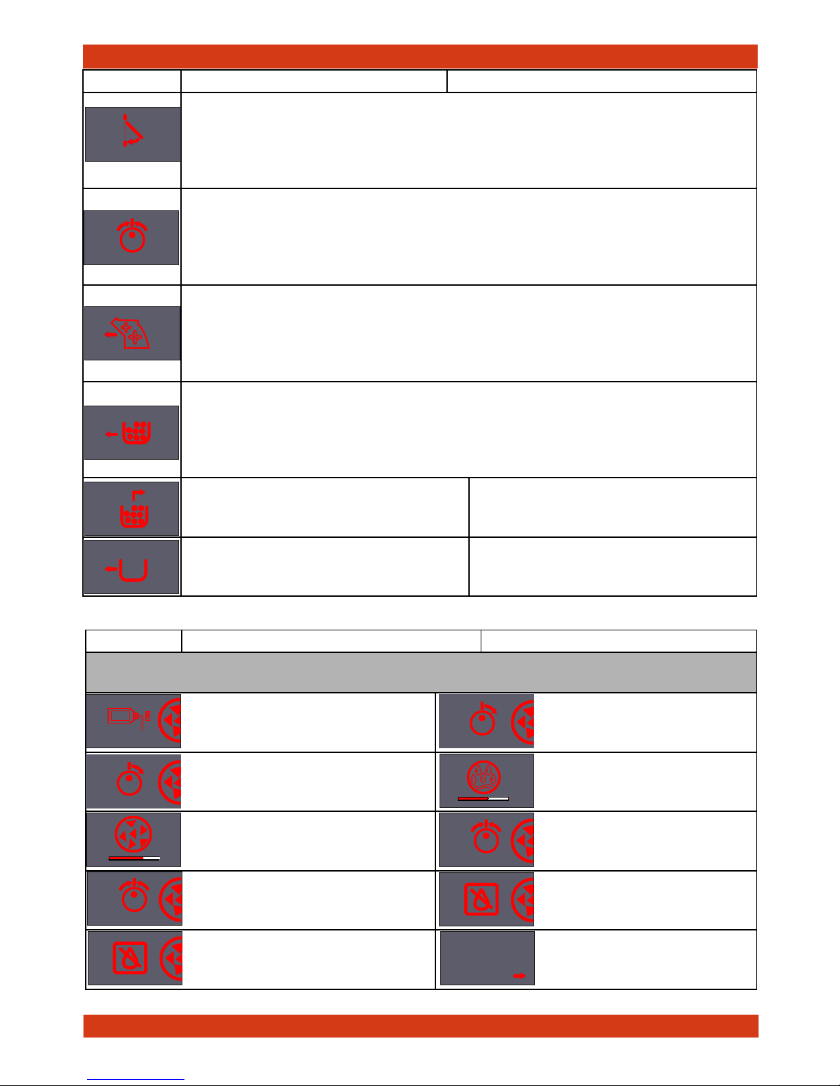
Indications Causes Solutions
Switch the machine off, wait for 30
seconds and switch it back on again.
Repeat 2 or 3 times.
If the machine does not start, remove
brewing unit, clean it, grease it and reinsert. If the problem persist contact the
Service Centre
Water circuit fi ll request
Turn the knob to the cup
Circuit fi lling in progress
When the fi lling cycle ends turn the knob
back to the central position
No coffee beans inside container.
After fi lling the coffee container, start the
cycle again
No water
Fill the water tank
Page 17
SYNTIA 03 BRIEF INSTRUCTIONS
Saeco International Group Page 3 / 07
Indications Causes Solutions
DESCALING CYCLE
(press the Aroma/pre-ground coffee key for 5 sec)
1) Pour the descaler into the
water tank 6) Open the hot water valve
2) Open the hot water valve
7) Rinsing in progress
3) Descaling in progress
8) Close the valve
4) Close the valve
9) Fill the tank with fresh
water
5) Fill the tank with fresh water
10) Press the key indicated
by the arrow
ESC
OK
END
Indications Causes Solutions
Service door open: Close it.
If the service door is opened while product is being dispensed, the appliance stops
dispensing and starts a 30 sec. countdown before cancelling the dispensing process.
The countdown can be stopped by closing the service door and operation will resume
from its stopping point.
Turn the hot water/steam valve knob to the correct position.
If the knob is turned (open) while product is being dispensed, the appliance stops
dispensing and starts a 30 sec. countdown before cancelling the dispensing process.
The countdown can be stopped by closing the knob and operation will resume from
its stopping point.
No coffee unit.
If the brewing unit is removed while product is being dispensed, the appliance stops
dispensing and starts a 30 sec. countdown before cancelling the dispensing process.
The countdown can be stopped by re-inserting the brewing unit and closing the
door; operation will resume from its stopping point.
No dregs drawer.
If the dregs drawer is removed while product is being dispensed, the appliance stops
dispensing and starts a 30 sec. countdown before cancelling the dispensing process.
The countdown can be stopped by re-inserting the dregs drawer and operation will
resume from its stopping point.
Empty the dregs drawer
To reset the grounds counter, wait until
there are no dregs displayed in the
symbol (5 sec.)
Insert dregs drawer
When the counter is cleared there will be
no dregs displayed in the symbol
30
30
30
30
Page 18

SYNTIA 03 BRIEF INSTRUCTIONS
Saeco International Group Page 4 / 07
MENU
(commands and programming)
You can go to the programming menu only in “Stand-by” mode
Press the ON/OFF button to put the machine in Stand-by.
Stand-by.
When the machine is in Stand-by, press the button “ “ to go to programming,
advancement between functions and memory
The buttons “ “ and “ “ let you change the value of the function amongst
those on the page.
Coffee temperature:
This function allows the coffee dispensing temperature to be adjusted
Timer (Stand-by):
This function lets you adjust the time for switching to Stand-by after the last
dispensing.
Contrast:
This function allows the display contrast to be adjusted for better viewing of
the messages.
Water hardness:
This function lets you adjust the water hardness so that machine maintenance
is managed better
= very soft water =soft =hard =very hard
“INTENZA” water fi lter
This function lets you manage the “INTENZA” water fi lter.
Factory settings
This function allows the factory values to be reset
MENU
ESC
-
+
MAX
MED
MIN
ESC
-
+
180’
60’
30’
15’
ESC
-
+
ESC
-
+
ESC
-
+
ON
OFF
RESET
ESC
-
+
YES
NO
Page 19

SYNTIA 03 BRIEF INSTRUCTIONS
Saeco International Group Page 5 / 07
Indications Status Causes Solutions
Fixed
Fixed
Machine at correct temperature
- for coffee bean dispensing
- for hot water dispensing
Proceed with the dispensing
process
Fixed
Fixed
Machine at correct temperature
- for ground coffee dispensing (preground)
Proceed with the dispensing
process
Slow blinking
Machine in phase for dispensing 1
cup of espresso
Dispense 1 espresso
Rapid
blinking
Machine in phase for dispensing 2
cups of espresso
Dispense 2 cups of espresso
Slow blinking
Machine in phase for dispensing 1
cup of long coffee
Dispense 1 cup of long
coffee
Rapid
blinking
Machine in phase for dispensing 2
cups of long coffee
Dispense 2 cups of long
coffee
Blinking
Blinking
Machine in the phase of programming the quantity of coffee to be dispensed (Keep the espresso or long
coffee button pressed)
Stop dispensing as desired
Machine ready signals
3.1.2 ustomer menu and Focus programming
MEMO
MEMO
MEMO
MEMO
MEMOMEMO
MEMO
MEMO
MEMO
MEMO
MEMO
MEMO
MEMO MEMO
Page 20

SYNTIA 03 BRIEF INSTRUCTIONS
Saeco International Group Page 6 / 07
Notice signals
Segnali di allarme
Indications Status Causes Solutions
Blinking
Machine in alarm status
- Put the hot water/steam tap knob
back in the correct position
- The brew group is not inserted
- Close the service door
Fixed
Empty the dregs drawer
Blinking
Insert dregs drawer
Fixed
No beans inside the coffee
container
Re-start the cycle after fi lling
the container
Fixed
Fill water tank
Indications Status Causes Solutions
Blinking
Machine in alarm status
- for coffee bean dispensing
- for hot water dispensing
With for the dispensing process
Cyclical
Machine in rinsing phase
Wait for the machine to end
the operation
Fixed
The appliance requires a descaling
cycle
Carry out the descaling cycle
Blinking
The machine needs water circuit
priming
Prime the water circuit
MEMO
MEMO
MEMOMEMO
Page 21

SYNTIA 03 BRIEF INSTRUCTIONS
Saeco International Group Page 7 / 07
3.2. Operation, cleaning and maintenance
CLEANING AND TECHNICAL SERVICING
A Empty the dregs drawer When indicated
B Empty the drip tray As necessary
C Clean the water tank Weekly
D Clean the coffee bean container As necessary
E Clean the casing As necessary
F
Clean the brewing unit Every time the coffee bean container is fi lled or
weekly
Lubricate the brewing unit Once a month or every 500 dispensing
procedures
Clean the unit housing Weekly
H Perform descaling When indicated
Descaling cycle frequency
Hardness Water hardness Without limescale fi lter With limescale fi lter
1 Soft water (up to 7°dH) Approx. every 3 months /
120 litres
Approx. every 6
months / 240 litres
2 Medium water (7° - 14°dH) Approx. every 2 months /
90 litres
Approx. every 4
months / 180 litres
3 Hard water (15° - 21°dH) Approx. every 6 weeks or
60 litres
Approx. every 3
months / 120 litres
4 Very hard water (over 21°dH) Approx. every 4 weeks or
30 litres
Approx. every 6 weeks
or 60 litres
Operating the machine
1 Fill water tank
2 Fill the coffee bean
container
3 Switch on the appliance
4 Fill the circuit Place a container under the steam arm, turn the selector to
the ”
“ symbol and wait for the appliance to return to coffee
ready status.
5 Press the coffee key Press once for one coffee; twice for two coffees
Page 22

Saeco International Group SYNTIA
CHAPTER 4
OPERATING LOGIC
Page 23

SYNTIA 04 OPERATING LOGIC
Saeco International Group Page / 06
4.1. Water circuit
Compensation valve 16/18 bar
Steam hose connection
Steam hose
Compensation valve water outlet
Turbine
1400 W boiler
To brewing unit
Water tank rapid
connection
Steam
valve
Pump
• Traditional water system
• Turbine – Amount of coffee dispensed into the cup
• Reciprocating piston type pump (13 - 15 bar)
• Compensation valve (opening pressure 16 - 18 bar)
• Boiler – 1400 W
• Presblok valve – select coffee – hot water - steam
Boiler
Turbine
Brewing unit
Coffee dis-
penser
Water collection tank
Pump
Compensation
valve
Water tank
Water / steam
Control
ringnut
Presblock
valve
01
Page 24

SYNTIA 04 OPERATING LOGIC
Saeco International Group Page / 06
4.2. Control ringnut and valve
No DESCRIPTION
1 Mushroom valve cap
2 Spring for mushroom valve
3 Mushroom valve support
4 Mushroom valve
5 Sealing OR
1
2
3
4
5
When dispensing coffee the mushroom valve opens at 4 bar +/- 0.5
Manual opening when dispensing water
Manual opening when dispensing steam
02
TOTAL STROKE
COFFEE CLOSED
-30° + 30°
Valve opening
stroke
Valve closing
stroke
STEAM
OPEN
WATER
OPEN
Extra stroke Extra stroke
Page 25

SYNTIA 04 OPERATING LOGIC
Saeco International Group Page / 06
Notes: * Only with Pre-brewing
4.3. Coffee cycle operating diagram
MS status
OFF
Single microswitch gear motor
ON
Switching on
When the machine is switched on, the gear motor repositions itself as follows:
- It acts on microswitch 1 (see following. section)
- The gear motor changes its rotation direction and moves upwards again by approx. 1-2 mm
- The boiler begins to heat water for approx. 45 seconds. It absorbs all the available heating
power in order to reach the optimal temperature. The temperature will then remain at a constant
level.
Coffee cycle
1. The coffee grinder starts the grinding process (controlled by pulses generated by a sensor)
2. The gear motor (brewing unit) moves to the dispensing position
3. Preliminary dispensing phase (short pump activity, short pause)
4. Product dispensing (the pump operation period is defi ned by the amount of product dispensed)
5. The gear motor moves to its home position (the dregs are expelled automatically)
Main switch ON START STOP
Time
Coffee grinder
Heating
Pump
Brewing unit gear
motor
Status Heating Ready Coffee cycle
Pulses
(Dosage)
Pump activity
(turbine pulses)
depending on the
product quantity
selected
approx.
45 secs.
*
03
Page 26

SYNTIA 04 OPERATING LOGIC
Saeco International Group Page / 06
Temperature sensor
An NTC is used as a temperature sensor; in the event of overheating this reduces boiler element power consumption.
The electronic system detects the current boiler temperature from the drop in voltage and adjusts it accordingly.
Resistor values: see table
4.5. Temperature sensor (adjustment)
Temp. (°C) R nom (kΩ) ΔR (+/- %)
20 61,465 8,6
50 17,599 5,9
75 7,214 4,1
80 6,121 3,7
85 5,213 3,4
90 4,459 3,1
100 3,3 2,5
125 1,653 3,9
150 0,893 5,1
4.4. Single microswitch
The gear motor is powered by a direct current motor that engages with the smaller
double toothed wheel using a worm screw.
The unit is mounted on the axle of the large
gear wheel and when a coffee is requested,
it moves from the home position to the dispensing position, and then back to the home
position again.
- Home position: 1
- Dispensing position: 2
2
1
04
Page 27

SYNTIA 04 OPERATING LOGIC
Saeco International Group Page / 06
4.6. Coffee grinder function
2
3
4
5
6
1
4.7. Low bean level detection, dose quantity adjustment, coffee grinder
blocked
t1
V
t2
t3
t4
t
Without beans n=100%
With beans n=100%
Without beans n=50%
With beans n=50%
Ceramic coffee grinder
The coffee grinder is driven by a direct current motor (1) using a worm screw helicoidal wheel
transmission (2).
The worm screw (2) drives a plastic gear wheel (3), which turns the lower grinder (4) and the
increment pin (5)
There are two magnets (6) in the gear wheel; at every rotation these transmit two pulses to a Hall
sensor, which in turn transmits them to the electronic system.
No coffee
A low coffee bean level is detected by the Hall sensor, after
variations in the pulse frequency (with or without coffee).
If there are no coffee beans (operation while empty), the
number of rotations – and therefore the number of pulses –
will be greater
t1 = No coffee indication
If, however, there are coffee beans, the number of rotations will be lower due to the force created by the grinding
t2 = no indication
t3 and t4 = this measurement is performed at the end of
each grinding process
Dose quantity adjustment
The dose quantity is adjusted in accordance with the pulses
detected (number of rotations proportional to the selected
fl avour – mild, medium or strong)
Coffee grinder blockage
If the coffee grinder becomes blocked for any reason,
pulses will no longer be transmitted to the electronic system and the grinder will come to a stop
05
Page 28

SYNTIA 04 OPERATING LOGIC
Saeco International Group Page / 06
06
4.8 Dose self-learning (SAS)
The aim of this function is to automatically regulate the average dose of ground coffee (SELFLEARNING); this occurs by means of an algorithm based on three pieces of information detected
by the machine electronic board:
1. Number of coffee grinder pulses during the grinding cycle
2. Max. average value of the power consumed by the group motor during the coffee brewing cycle
3. Aroma selected by the user
The algorithm compares the maximum average value of the power consumed by the group motor
with the value listed in the table for the selected aroma, in order to calculate the new grinding
pulse value for the next coffee produced.
If the power consumption value is less than the minimum current value, the
grinding pulses will be increased by 2.
If the power consumption value is greater than the maximum current value, the grinding pulses
will be decreased by 4.
If the power consumption value falls within the “over-torque” interval, the product will be
dispensed and the grinding pulses will be decreased by 10.
If the power consumption value falls within the “abort cycle” interval, the pad will be expelled and
the grinding pulses will be decreased by 10.
If the “pre-ground” fl avour is selected by the user, no modifi cation will be made.
This guarantees that, regardless of the coffee type used, the grinding level setting
and the wear on the grinders always remains constant.
Important:
For perfect operation, machine adjustment should take place in the area of the fi elds
highlighted in green (A, B, C). When the type or brand of coffee is changed, there may be
variations in the size of the beans and their stickiness or roasting level. This leads to variations
in power consumption (mA), with resulting excessive or insuffi cient doses (until the necessary
adjustments have been made to compensate for this change).
Caution: In the case of excessive dosage, powder may be expelled into the dreg
drawer. This is not a fault, but can occur during preliminary operation or after a
service.
Setting/Status
Power consumption
in mA
Pulses corrected in the next grinding process
Exceeded by Defi cient by
A Mild aroma 200 - 300 mA - 4 +2
B Medium Aroma 301 - 450 mA - 4 +2
C Strong Aroma 451 - 600 mA - 4 +2
D Over-limit 601 - 800 mA - 4
E Over-torque 801 - 1,000 mA - 10
F Abort cycle > 1000 mA - 10
Page 29

Saeco International Group SYNTIA
CHAPTER 5
SERVICE MODE
Rev.01 February 2010
Page 30

SYNTIA 05 SERVICE MODE
Saeco International Group Page 1 / 07
5.1. Digital test mode
To enter Test Mode
1. place the control knob in the water position
2. keep the espresso coffee key pressed
3. switch the appliance on from the 0/I button
located at the rear of it
4. release the espresso coffee key
lev.
pos.
knob
display key function notes
L0
View software
version
The software version must be
the same as that stated on the
MicroProcessor plate
PRESS THE ON/OFF KEY TO ACCESS THE NEXT LEVEL UP
L1
Initial condition with no keys pressed
no. 1 from “ N to
Y ” and display
from green
change to red
If display does not change and
remains as initial condition, replace
interface card and/or fl at cable
JP21. If the colour of the display
remains green,
check JP4 wiring from interface
card to display
no. 2 from “N to
Y” and display
from green
change to orange
no. 3 from “N to
Y” and display
remains green
If display does not change and
remains as initial condition, replace
interface card and/or fl at cable
JP21.
PRESS THE ON/OFF KEY TO ACCESS THE NEXT LEVEL UP
Operational check – keys
Software
version
1 2 3 4
Y N N N
KEYBOARD
1 2 3 4
N N Y N
KEYBOARD
1 2 3 4
N Y N N
KEYBOARD
1 2 3 4
N N N N
KEYBOARD
00.02.00
FIRMWARE
Page 31

SYNTIA 05 SERVICE MODE
Saeco International Group Page 2 / 07
lev.
pos.
knob
display key function notes
L2 Initial condition:
Unit inserted, dregs drawer inserted, water tank full,
side door closed, control knob in coffee position.
Remove
water
tank
TANK-H2O
display
changes from
“Y” to “N”
If TANK-H2O display does not change,
check capacitive sensor and JP23
wiring
Remove
dregs
drawer
DREGS display
changes from
“Y” to “N”
If display message does not change,
check dregs drawer microswitch and
JP16 wiring
Open
side
door
DOOR display
changes from
“Y” to “N”
If DOOR display does not change,
check door microswitch and JP16
Remove
coffee
unit
BU-P display
changes from
“Y” to “N”
If BU-P display does not change, check
unit presence microswitch and JP14
Knob in
water
pos.
TAP-WATER
display from
“N to Y”
If TAPWATER, TAPCOFFE, TAPSTEAM,
TAP - ERR display does not change,
check knob card and/or connection
wiring with interface card JP2.
If TAP - ERR display continues to show
“Y”, check magnet polarity on knob
support
Knob in
coffee
pos.
TAP-COFFE
display from
“N to Y”
Knob in
steam
pos.
TAP-STEAM
display from
“N to Y”
Incorrect
position
Knob in
incorrect
pos.
TAP - ERR
display from
“N to Y”
PRESS THE ON/OFF KEY TO ACCESS THE NEXT LEVEL UP
Operational check
microswitches and
sensors
TAPCO FFE=Y
TAPSTEAM=N
TAPWATER=N
TAP - ERR =N
TANK-H2O =Y
DOOR=N
BU-P= Y
DREG=Y
INPUTS
TAPCO FFE=N
TAPSTEAM=N
TAPWATER=Y
TAP - ERR =N
TANK-H2O =Y
DOOR=Y
BU-P= Y
DREG=Y
INPUTS
TAPCO FFE=Y
TAPSTEAM=N
TAPWATER=N
TAP - ERR =N
TANK-H2O =Y
DOOR=Y
BU-P= Y
DREG=Y
INPUTS
TAPCO FFE=N
TAPSTEAM=Y
TAPWATER=N
TAP - ERR =N
TANK-H2O =Y
DOOR=Y
BU-P= Y
DREG=Y
INPUTS
TAPCO FFE=N
TAPSTEAM=N
TAPWATER=N
TAP - ERR =Y
TANK-H2O =Y
DOOR=Y
BU-P= Y
DREG=Y
INPUTS
TAPCO FFE=Y
TAPSTEAM=N
TAPWATER=N
TAP - ERR =N
TANK-H2O =Y
DOOR=Y
BU-P= N
DREG=Y
INPUTS
TAPCO FFE=Y
TAPSTEAM=N
TAPWATER=N
TAP - ERR =N
TANK-H2O =Y
DOOR=Y
BU-P= Y
DREG=Y
INPUTS
TAPCO FFE=Y
TAPSTEAM=N
TAPWATER=N
TAP - ERR =N
TANK-H2O =N
DOOR=Y
BU-P= Y
DREG=Y
INPUTS
TAPCO FFE=Y
TAPSTEAM=N
TAPWATER=N
TAP - ERR =N
TANK-H2O =Y
DOOR=N
BU-P= Y
DREG=N
INPUTS
Page 32

SYNTIA 05 SERVICE MODE
Saeco International Group Page 3 / 07
lev.
pos.
knob
display key function notes
L3
Initial status with no keys pressed
Bring the
unit to the
“WORK”
position
CUR= --- indicates the gearmotor
absorption; this value must be:
WITHOUT BREWING UNIT INSERTED
lower than 200mA
WITH BREWING UNIT INSERTED
lower than 300 mA
ERROR: WORK display shows “N”, display from green
change to red. Check gearmotor gear microswitch
(broken or inserted incorrectly) or motor (locked).
Check JP16 wiring.
ERROR: (WITHOUT UNIT inserted) If the gearmotor
motor current absorption is higher than 200mA,
display from green change to red. Check gearmotor
unit and/or motor
ERROR: (WITH UNIT inserted) If the gearmotor motor
current absorption is higher than 300mA, display from
green change to red. Check gearmotor unit and/or
motor
Bring the unit
to the “HOME”
position
CUR= --- corresponds to the
gearmotor absorption; this value must
be:
WITHOUT UNIT INSERTED
lower than 200mA
WITH UNIT INSERTED
lower than 300 mA
ERROR: HOME display shows “N”, display from green
change to red: check gearmotor gear microswitch
(broken or inserted incorrectly), gearmotor motor
(locked), wiring JP16
ERROR: (WITHOUT UNIT inserted) Gearmotor motor
current absorption higher than 200mA, display from
green change to red: check gearmotor unit and/or
motor
ERROR: (WITH UNIT inserted) Gearmotor motor
current absorption higher than 300mA, display from
green to red: check gearmotor unit and/or motor
PRESS THE ON/OFF KEY TO ACCESS THE NEXT LEVEL UP
WORK=N
HOME=Y CUR= 193
BU PAGE
WORK=N
HOME=N CUR= 497
BU PAGE
WORK=N
HOME=N CUR= 203
BU PAGE
WORK=N
HOME=N CUR= 337
BU PAGE
Operational check
brewing unit
WORK=Y
HOME=N CUR= 0
BU PAGE
WORK=Y
HOME=N CUR= 178
BU PAGE
WORK=N
HOME=N CUR= 497
BU PAGE
WORK=N
HOME=N CUR= 203
BU PAGE
WORK=N
HOME=N CUR= 337
BU PAGE
Page 33

SYNTIA 05 SERVICE MODE
Saeco International Group Page 4 / 07
lev.
pos.
knob
display key function notes
L4
Initial status with no keys pressed
and valve in water position
Water supplied by the steam hose: the number
indicating fl ow meter pulses (IMP) must increase.
L/H must be between 12 and 16
ERROR: Display from green change to red and 0
pulses: check pump, turbine, turbine wiring and/or
CPU/POWER card connection (JP5), pump wiring and/
or CPU/POWER card connection (JP24)
PRESS THE ON/OFF KEY TO ACCESS THE NEXT LEVEL UP
L4
Initial status with no keys pressed
The number indicating COFFEE GRINDER MOTOR rotation increases up to 40. The two other numbers on the
display are not important for the test
ERROR: The number is 0 with no coffee grinder motor rotation, display from green change to red: check
grinder sensor and/or motor, sensor wiring and/or
CPU/POWER card connection (JP2), grinder motor wiring and/or CPU/POWER card connection (JP8)
Power absorption OK, the HEATER display changes
from “OFF” to “ON” and the temperature increases
ERROR: “SHORT” appears below HEATER, boiler
temperature sensor disconnected, display from green
change to red: check boiler sensor wiring and/or CPU/
POWER card connection (JP13 may be disconnected)
ERROR: “OPEN” appears below HEATER, boiler
temperature sensor open, display from green change
to red: check boiler sensor wiring and/or CPU/POWER
card connection (JP13 may be disconnected)
ERROR: Power absorption KO and temperature does
not increase: check power supply wiring and/or CPU/
POWER card connection (JP17-3)
Operational check – coffee
grinder - boiler
OFF
30
0
0
15
HEATER GRINDER
OFF
30
40
15
14
HEATER GRINDER
40
OFF
30
0
0
15
HEATER GRINDER
ON
49
40
15
14
HEATER GRINDER
OFF
159
SHORT
40
15
14
HEATER GRINDER
OFF
71
OPEN
40
15
14
HEATER GRINDER
Operational check –
pump
IMP = 0
L/H = 0
PUMP
IMP = 1 12
L/H = 13
PUMP
IMP = 0
L/H = 0
PUMP
Page 34

SYNTIA 05 SERVICE MODE
Saeco International Group Page 5 / 07
5.1.2 Focus test mode
lev.
pos.
knob
symbol
button
status
press
function
L1
Initial LED status at level 1
If the screen does not change from the initial status,
replace the interface card and/or the JP21 fl at cable.
PRESS THE ON/OFF KEY TO ACCESS THE NEXT LEVEL UP
Operational check - keys
MEMO
MEMO
lev.
pos.
knob
symbol button function
L2
Initial LED status at level 2
Remove water
tank
If the LED does not turn on, check the
capacitive sensor and the JP22, JP23 wiring
Open service
hatch
If the LED does not turn on, check the
hatch microswitch and the JP16 wiring
Remove dregs
drawer
If the LEDS do not turn on, check the
microswitch and the JP16 wiring
Remove the brew
group
If the LED does not turn on, check the
group microswitch and the JP14 wiring
If the LEDS do not turn on, check
the knob card and the JP21 wiring
If the LED does not turn on, check the
knob card and the JP21 wiring
PRESS THE ON/OFF KEY TO ACCESS THE NEXT LEVEL UP
Operational check -
microswitches and sensors
MEMO
MEMO
MEMO
MEMO
1
3
To enter Test Mode
1. position the control knob in the hot water position
2. keep the espresso coffee key pressed
3. turn on the machine by pressing the 0/I button on the
rear (espresso coffee and long coffee blink alternatively)
4. release the espresso coffee button (you go directly to the
1st level of the Test Mode)
To go to a higher level, press the On/Off button
MEMO MEMO
2
Page 35

SYNTIA 05 SERVICE MODE
Saeco International Group Page 6 / 07
boiler
lev.
pos.
knob
symbol
status
press
function
L5 If the symbol appears, the boiler sensor is
interrupted. Check the boiler sensor wiring and/or
the connection on the CPU/Power card (JP13)
If the the current absorption is KO, check the
power wiring and/or the connection on the CPU/
Power card (JP17-3)
The coffee grinder is enabled by pressing the
“AROMA” button, and the button starts to blink
.If this does not occur and the symbol turns
on, check the sensor and/or the coffee grinder
motor, the wiring of the sensor and/or the connection on the CPU/Power card (JP2), the wiring of
the coffee grinder motor and/or the connection on
the CPU/Power card (JP8)
Operational check -
coffee grinder and
MEMO
MEMO
lev.
pos.
knob
symbol
status
press
function
L4
Initial LED status at level 4
The water is dispensed from the steam pipe and
blinks The symbol turns on if water is not
dispensed. Verify checks at the pump, pump wiring
and/or connection on the CPU/Power card(JP24),
turbine, turbine wiring and/or connection on the
CPU/Power card(JP5).
To check correct passage of water from the coffee duct, return to level 2 (brewing unit functional
check), put the unit in the “Work” position, and the
knob will blink in the coffee position
PRESS THE ON/OFF KEY TO ACCESS THE NEXT LEVEL UP
Operational check -
pump
MEMO
MEMO
MEMO
MEMO
lev.
pos.
knob
symbol
status
press
function
L3
Initial LED status at level 3
The brewing unit goes into the “Work” position and
the button turns on . The symbol turns on if
strain is excessive. Check operation of the gearmotor and microswitch of the gear (broken or inserted
incorrectly).Check the JP16 wiring
iturns
off as
soon
as it is
pressed
The brewing unit goes into the “Home” position
and the button turns on . The symbol turns
on if strain is excessive. Check operation of the
gearmotor and microswitch of the gear (broken or
inserted incorrectly). Check the JP16 wiring
PRESS THE ON/OFF KEY TO ACCESS THE NEXT LEVEL UP
Operational check -
brewing unit
MEMO
MEMO
MEMO
MEMO
MEMO
MEMO
MEMO
Page 36

SYNTIA 05 SERVICE MODE
Saeco International Group Page 7 / 07
ERROR
CODES
DESCRIPTION
01
The grinder is blocked (burrs jammed or sensor not reading properly)
03
The brewing unit is blocked in work position (microswitch not released
in up position after 3", torque error trying to move down, descent time
out exceeded)
04
The brewing unit is blocked in home position (microswitch not released
in down position after 3", torque error trying to move up, ascent time
out exceeded)
05
Water circuit / fl ow meter problems (water circuit blocked or no fl ow
meter signal)
10
Boiler temperature sensor short circuited
11
Boiler temperature sensor open circuit
14
The boiler temperature has exceeded the maximum allowed value
(165°c)
15
The boiler temperature has not increased by x°c in y sec (boiler power
supply disconnected, incorrect boiler fi tted must be a 1300W boiler,
partial power supply to boiler, cut out thermostat tripped)
19
Mains voltage trouble
5.2. Error codes
Page 37

Saeco International Group SYNTIA
CHAPTER 6
SERVICING AND
MAINTENANCE
Page 38

SYNTIA 06 SERVICING AND MAINTENANCE
Saeco International Group Page 1 / 02
Action
1 Visual inspection (transport damage)
2 Machine data check (rating plate)
3 Operational check / problem analysis
4 Opening machine
5 Visual inspection
6 Operational tests
7 Repairing the faults encountered
8 Checking any modifi cations (view info, new sw, etc.)
9 Service activities in accordance with the operating schedule
10 Internal cleaning
11 Operational test while the appliance is open
12 Assembly
13 Final inspection test
14 Draining the circuit (in winter)
15 External cleaning
16 Lubricating the brewing unit with suitable grease
17 Insulation test HG 701 (dielectric)
18 Documentation
S Replacement P Cleaning
ES Visual inspection TR Noise test
D Descaling R Adjustment
Component Action Support/tool
Water fi lter P/S
Water tank lip seal S
Boiler pin O-ring S
Brewing unit ES/P Grease solvent / Grease
Hoses, attachments and Oetiker clamps ES
Pump ES/TR
Gear motor ES/TR
Coffee grinder P/R Vacuum cleaner / brush
Water circuit D Saeco descaler
Hot water/steam valve ES/S
6.2. Service schedule
6.1. Repair schedule
Page 39

SYNTIA 06 SERVICING AND MAINTENANCE
Saeco International Group Page 2 / 02
Test Procedure Support/tool Standard Tolerance
Espresso
2-3 Espressos for
adjustment purposes
Measuring
beaker
Same amount 15%
Coffee
2-3 Coffees for
adjustment purposes
Measuring
beaker
Same amount 15%
Noise Standard
Amount of
"crema"
Blow into the cup until
the "crema" separates
The "crema" should
come together
again to form a
complete layer
"Crema"
colour
Hazel brown
Temperature
Reading taken while
dispensing
Thermometer 84 °C ± 4 °C
Grinding level
Check the grain size of
the ground coffee
Hot water Dispense water
Steam Dispense steam
Grounds
drawer
missing
indication
Remove the grounds
drawer
Grounds drawer
missing indication
Low bean
level
indication
Start brewing a coffee
while the coffee bean
container is empty
Low bean level
indication
6.3. Final test
Page 40

Saeco International Group SYNTIA
CHAPTER 7
DISASSEMBLY
Rev.01 February 2010
Page 41

SYNTIA 07 DISASSEMBLY
Saeco International Group Page / 09
Disassembling the Top cover
1) Remove the grounds drawer,
water tank, coffee container lid,
drip tray, brewing unit, steam
wand covering cap, pannarello
and control knob cover
2) Unscrew the screws shown
and remove the fi nger protection
device and coffee hopper
3) Unscrew the screw shown and
extract the control knob
4/5) Unscrew the screw shown
and extract the coffee dispenser
fi xed support by lifting it upwards
6) Unscrew the screws shown
located inside the compartments
containing the water tank and
grounds drawer
7) Lift the lid and disconnect the
earth wire shown
7.1. Outer elements disassembly
2
1
3
4
5
6
7
When refi tting the machine cover, take great care not
to scratch the keypad cover.
Put a sheet of paper on the keypad cover (see photo)
before refi tting the machine cover and slide it out at
the end of assembly
01
Page 42

SYNTIA 07 DISASSEMBLY
Saeco International Group Page / 09
1) Unscrew the screw shown
2) Slide out the fork clip
3) Unscrew the screws shown and remove
the support
4) Coffee dispenser assembly parts
Disassembling the rear cover
Unscrew the screws shown
Disassembling the side door
Lift the door and unhook it from the support
hinge
Disassembling the side cover
Unscrew the screws shown and disconnect
the earth wire
1
2
3
4
7.2. Coffee dispenser disassembly
02
Page 43

SYNTIA 07 DISASSEMBLY
Saeco International Group Page / 09
1) Unscrew the screw shown, remove
the lid, glass, frame, keypad and seal
2) Release the display support
3) Unscrew the screws shown and
remove the spring washer
4) Parts
5) Release the control knob circuit board
6) Release the display
7) Release the keypad circuit board and
disconnect the display
1
4
3
2
65
7
7.3.1 Disassembling Keypad card and Digital Control Knob
03
7.3.2 Disassembling Keypad card and Focus Control Knob
03
1) Remove the display frame by lifting it and slip off the
upper cover
2) Slip off the fl at cable and loosen the highlighted screw
3) Loosen the highlighted screws and remove the elastic
washer
1
4
3
2
4) Display and interface cards as
sembly
Page 44

SYNTIA 07 DISASSEMBLY
Saeco International Group Page / 09
1) Loosen the screw shown and remove
the card protection
2) Slide out the card, removing all
connections
1
2
7.5. Gearmotor disassembly
2
A
B
D
E
F
C
4
H
L
3
B
P
1
1) Loosen the screws holding the boiler pin in place,
remove it and loosen the other screws shown
2) The following are located inside the compartment
protected by the casing:
- Brew drive (A) with gears (B) and (C) for
transmission and timing of the dispensing head.
- Grounds drawer present microswitch (D).
- Brewing unit present microswitch (E).
- Microswitch (F) detecting brewing unit home and
work positions.
- Remove the gear (C) that meshes with the motor
transmission shaft
- Remove the large gear (B)
- Remove the motor (A), complete with transmission
shaft
3) Replace the gear (B), making sure that the
imprint of the arrow is aligned with the opening
containing the pin (P)
4) When replacing the motor and the transmission
shaft, make sure the bearings (L) are in the right
position.
Grease the shaft thoroughly and evenly
7.4. Power/CPU disassembly
04
Page 45

SYNTIA 07 DISASSEMBLY
Saeco International Group Page / 09
1) Remove the coffee grinder noise reduction
cover
2) Remove the boiler insulation
3) Unscrew the screws shown
4) Loosen the screw and remove the plastic
support.
Disconnect the hoses and the connections
7.6. Boiler disassembly
1
2
3
7.7. Valve disassembly
1) Remove the boiler pin
2) Remove the control knob cover
and unscrew the screw as indicated
3) Lift and remove the dispenser
assembly, slide out the fork clip
shown and unscrew the screws
holding the front piece
4) Unscrew the screws shown to
remove the front piece support
5) Remove the spring washer and
the control knob gear (steam/water)
1
3
2
4
Front piece
5
05
Page 46

SYNTIA 07 DISASSEMBLY
Saeco International Group Page / 09
6) Remove the screws shown
to remove the insert on the
base of the casing
7) Remove the screws shown
and disconnect the valve from
the water connections
7) Remove the screws shown
and disconnect the valve from
the mesh hoses
7.8. Pump and turbine disassembly
6
7
PUMP
Remove the connection 1, disconnect the silicone hoses 2
Unscrew the safety valve and remove the pump from the
two supports
TURBINE
Remove the connection and disconnect the silicone hoses
2
2
1
06
Page 47

SYNTIA 07 DISASSEMBLY
Saeco International Group Page / 09
1) Boiler connection
2) Other connections
Replacing the hoses
1) Use a suitable pair of pliers to
remove the clamp (as illustrated)
2) Tighten the clamp as illustrated
7.9. OETIKER clamps assembly and disassembly
1
1
2
2
07
Page 48

SYNTIA 07 DISASSEMBLY
Saeco International Group Page / 09
1) To remove the coffee grinder, simply slide it out
and remove its connections
2) When replacing it, make sure the spring (A)
and the coffee pipe (B) are positioned correctly
7.10. Coffee grinder disassembly
1
2
A
B
08
Page 49

SYNTIA 07 DISASSEMBLY
Saeco International Group Page / 09
7.11. Grinder adjustment/assembly and disassembly
1) To remove the upper grinder support, using a
hex key push down and turn clockwise to release
the grinder support from the bayonet coupling
2) To remove the grinder blade from the upper
support, turn it anti-clockwise until it detaches
from the bayonet coupling
3) To remove the lower grinder blade, keep the
increment pin (A) locked in position and turn the
grinder blade anti-clockwise, until it detaches from
the bayonet coupling
4) When refi tting the upper grinder support,
make sure you reposition it so that the mark is as
illustrated in the photo
1
2
3
A
4
09
Page 50

Saeco International Group SYNTIA
CHAPTER 8
NOTES
Page 51

SYNTIA 08 NOTES
Saeco International Group Page / 01
01
Page 52

Saeco International Group SYNTIA
CHAPTER 9
WATER CIRCUIT DIAGRAM
Page 53

SYNTIA 09 WATER CIRCUIT DIAGRAM
Saeco International Group Page / 01
9.1. Water circuit diagram
Steam tube pipe fi tting
Raccordo tubo vapore
Silicone tube - Tubo silicone
5x10 9972.176 (130mm)
Silicone tube - Tubo silicone
5x10 9912.122 (290mm)
Silicone tube - Tubo silicone
5x10 9972.176 (130mm)
Linen-faced silicone tube
Tubo silicone retinato
5x8,9 11005599 (190mm)
Safety valve
Valvola di sicurezza
11010166
Linen-faced silicone tube
Tubo silicone retinato
5x8,9 11003557 (260mm)
Water drain
Scarico acqua
To the Coffee spout
All'erogatore caffè
Linen-faced silicone tube
Tubo silicone retinato
5x8,9 11004050 (165mm)
Water tank
Serbatoio acqua
Flow meter
Turbina
Steam tube
Tubo vapore
Boiler
Caldaia
1300W
Steam/Water dispensing
Erogazione vapore/acqua
Pump
Pompa
01
Page 54

Saeco International Group SYNTIA
CHAPTER 10
ELECTRICAL
DIAGRAM
Page 55

SYNTIA 10 ELECTRICAL DIAGRAM
Saeco International Group Page / 01
10.1 Wiring diagram Digital
01
Page 56

SYNTIA 10 ELECTRICAL DIAGRAM
Saeco International Group Page / 01
10.2 Wiring diagram Focus
 Loading...