

Philips G3 EnviroDome Instruction Book
AutoDome
®
Instruction Book
EnviroDome
™
Indoor Pendant
In-ceiling Model
IMPORTANT SAFEGUARDS
1. Read Instructions - All the safety and operating
instructions should be read before the unit is operated.
2. Retain Instructions - The safety and operating instructions should be retained for future reference.
3. Heed Warnings - All warnings on the unit and in the
operating instructions should be adhered to.
4. Follow Instructions - All operating and use instructions
should be followed.
5. Attachments - Do not use attachments not recommended by the product manufacturer as they may
cause hazards.
6. Accessories - Do not place this unit on an unstable
stand, tripod, bracket, or mount. The unit may fall,
causing serious injury to a person and serious damage to
the unit. Use only with a stand, tripod, bracket, or
mount recommended by the manufacturer or sold with
the product. Any mounting of the unit should follow
the manufacturer's instructions and should use a
mounting accessory recommended by the manufacturer.
An appliance and cart combination should be moved
with care. Quick stops, excessive force, and uneven surfaces may cause the appliance and cart combination to
overturn.
7. Power Sources - This unit should be operated only from
the type of power source indicated on the marking label.
If you are not sure of the type of power supply you plan
to use, consult your appliance dealer or local power
company. For units intended to operate from battery
power or other sources, refer to the operating instructions. This equipment is to be isolated from the mains
supply by a limited power source as specified in
EN60950:1992 Clause 2.11. The LTC 5401 or
LTC 9540 are examples of such power sources.
8. Power Lines - An outdoor system should not be located
in the vicinity of overhead power lines or other electric
light or power circuits or where it can fall into such
power lines or circuits. When installing an outdoor system, extreme care should be taken to keep from touching such power lines or circuits as contact with them
might be fatal. U.S.A. models only - refer to the
National Electrical Code Article 820 regarding installation of CATV systems.
9. Servicing - Do not attempt to service this unit yourself
as opening or removing covers may expose you to dangerous voltage or other hazards. Refer all servicing to
qualified service personnel.
10. Replacement Parts - When replacement parts are
required, be sure the service technician has used
replacement parts specified by the manufacturer or
have the same characteristics as the original part.
Unauthorized substitutions may result in fire, electric
shock, or other hazards.
11. Safety Check - Upon completion of any service or
repairs to this unit, ask the service technician to perform safety checks to determine that the unit is in
proper operating condition.
12. Coax Grounding - If an outside cable system is connected to the unit, be sure the cable system is grounded. U.S.A. models only--Section 810 of the National
Electrical Code, ANSI/NFPA No.70-1981, provides
information with respect to proper grounding of the
mount and supporting structure, grounding of the coax
to a discharge unit, size of grounding conductors, location of discharge unit, connection to grounding electrodes, and requirements for the grounding electrode.
FCC & ICES INFORMATION (U.S.A.AND
CANADIAN MODELS ONLY)
WARNING - This equipment has been tested and found to
comply with the limits for a Class A digital device, pursuant
to Part 15 of the FCC Rules and ICES-003 of Industry
Canada. These limits are designed to provide reasonable protection against harmful interference when the equipment is
operated in a residential installation. This equipment generates, uses, and radiates radio frequency energy and, if not
installed and used in accordance with the instructions, may
cause harmful interference to radio communications.
Operation of this equipment in a residential area is likely to
cause harmful interference, in which case the user will be
required to correct the interference at his own expense.
Intensional or unintensional changes or modifications not
expressly approved by the party responsible for compliance
shall not be made. Any such changes or modifications could
void the user’s authority to operate the equipment.
If necessary, the user should consult the dealer or an experienced radio/television technician for corrective action. The
user may find the following booklet prepared by the Federal
Communications Commission helpful: "How to Identify
and Resolve Radio-TV Interference Problems." This booklet
is available from the U.S. Government Printing Office,
Washington, DC 20402, Stock No.004-000-00345-4.
SAFETY PRECAUTIONS
This label may appear on the bottom of the unit due to space
limitations.
The lightning flash with an arrowhead symbol
within an equilateral triangle is intended to alert the
user to the presence of uninsulated "dangerous voltage" within the product's enclosure that may be of sufficient
magnitude to constitute a risk of electric shock to persons.
The exclamation point within an equilateral tri-
angle is intended to alert the user to presence of
important operating and maintenance (servicing)
instructions in the literature accompanying the appliance.
Attention: Installation should be performed by
qualified service personnel only in accordance
with the National Electrical Code or applicable
local codes.
Power Disconnect. Units with or without ON-
OFF switches have power supplied to the unit
whenever the power cord is inserted into the
power source; however, the unit is operational only when
the ON-OFF switch is in the ON position. The power cord
is the main power disconnect for all units.
Warning
This is a class A product. In a domestic environment,
this product may cause radio interference, in which case
the user may be required to take adequate measures.
CAUTION:TO REDUCE THE RISK OF ELECTRICAL SHOCK, DO
NOT OPEN COVERS. NO USER SERVICEABLE PARTS INSIDE.
REFER SERVICING TO QUALIFIED SERVICE PERSONNEL.
WARNING
TO PREVENT FIRE OR SHOCK HAZARD, DO NOT EXPOSE UNITS
NOT SPECIFICALLY DESIGNED FOR OUTDOOR USE TO RAIN OR
MOISTURE.
1
2
COVER REMOVAL
24 VAC Units
Do Not Exceed 30 VAC Input. Voltage applied to the unit's
power input should not exceed 30 VAC. Normal input voltage is 24 VAC. User supplied wiring from 24 VAC supply to
unit must be in compliance with electrical codes (Class 2
power levels). Do not ground 24 VAC supply at power supply
terminals or at unit's power supply terminals.
This equipment is to be isolated from the mains
supply by a limited power source as specified in
EN60950:1992 Clause 2.11. The LTC 5401 or
LTC 9540 are examples of such power sources.
220-240 V, 50 Hz Power Cords
220-240 V, 50 Hz power cords, input and output, must
comply with the latest versions of IEC Publication 227 or
IEC Publication 245.
SECURITE
En raison de limitation de place, cette étiquette peut être
placée sur le dessous de l'appareil.
L'éclair fléché dans un triangle équilatéral, avertit
l'utilisateur de la présence d'une "tension dangereuse" non isolée à l'intérieur de l'appareil et d'une
valeur suffisante pour constituer un risque d'électrocution.
Le point d'exclamation contenu dans un triangle
équilatéral, avertit l'utilisateur de la présence, dans
la documentation qui accompagne l'appareil, de
consignes d'utilisation et de maintenance importantes.
Attention: L'installation doit être effectuée
uniquement par du personnel de service qualifié
conformément à la réglementation du Code
Electrique National ou à la réglementation locale.
Disjonction de l'alimentation. Les appareils avec
ou sans commutateurs ON-OFF sont alimentés à
chaque fois que le cordon d'alimentation est
branché à la source d'alimentation; toutefois, les appareils
disposant de commutateurs ON-OFF ne fonctionnnent que
lorsque le commutateur ON-OFF est sur la position ON.
Le cordon d'alimentation est la disjonction d'alimentation
principale pour tous les appareils.
SOURCES D'ALIMENTATION EXTÉRIEURES
Appareils 24 VCA
Ne pas excéder 30 VCA. La tension appliquée à l'entrée d'alimentation de l'appareil ne devrait pas excéder 30 VCA.
Toute installation électrique fournissant du 24 Volts courant
alternatif doit être conforme aux codes électriques. (Niveaux
d'alimentation de la Classe 2). Ne pas brancher une prise de
terre sur les bornes d'alimentation 24 Volts ou aux bornes
d'alimentation de l'appareil.
Les cordons secteur 220-240 V, 50 Hz
Les cordons secteur 220-240 V, 50 Hz, entrée et sortie,
doivent êtro conformes aux versions les plus récentes de la
publication 227 de la C.I.E. ou à la publication 245 de la
C.I.E.
SICHERHEITSVORKEHRUNGEN
Aus Platzgründen kann diese Warnung auf der Unterseite
des Gerätes angebracht sein.
Das Blitzsymbol im gleichseitigen Dreieck soll
den Benutzer auf nicht isolierte "Hochspannung"
im Gehäuse aufmerksam machen, die eventuell
stark genug ist, um einen elektrischen Schlag zu verursachen.
Das Ausrufezeichen im gleichseitigen Dreieck soll
den Benutzer auf wichtige Bedienungs- und
Wartungsanleitungen in der dem Gerät beige-
fügten Literatur aufmerksam machen.
Achtung! Die Installation sollte nur von qualifiziertem Kundendienstpersonal gemäß jeweilig
zutreffender Elektrovorschriften ausgeführt werden.
Netzanschluß. Geräte mit oder ohne Netzschalter
haben Spannung am Gerät anliegen, sobald der
Netzstecker in die Steckdose gesteckt wird. Das
Gerät ist jedoch nur betriebsbereit, wenn der Netzschalter
(EIN/AUS) auf EIN steht. Wenn man das Netzkabel aus der
Steckdose zieht, dann ist die Spannungszuführung zum
Gerät vollkommen unterbrochen.
ATTENTION
POUR ÉVITER LE RISQUE D'ÉLECTROCUTION OU D'INCENDIE,
NE PAS EXPOSER À LA PLUIE OU À L'HUMIDITÉ UN APPAREIL
NON CONÇU POUR UNE UTILISATION EXTÉRIEURE.
WARNUNG
UM FEUER ODER ELEKTRISCHE SCHLÄGE ZU VERMEIDEN, SETZEN SIE DAS GERÄT NIEMALS REGEN ODER FEUCHTIGKEIT
AUS.
WARNING:
REMOVAL OF THE COVER SHOULD ONLY
BE PERFORMED BY QUALIFIED SERVICE
PERSONNEL - NOT USER SERVICEABLE.THE UNIT
SHOULD ALWAYS BE UNPLUGGED BEFORE REMOVING THE COVER AND REMAIN UNPLUGGED WHILE
THE COVER IS REMOVED.
DANGER: POUR ÉVITER TOUT RISQUE D'ÉLECTROCUTION,
NE PAS OUVRIR LE BOÎTIER. IL N'Y A PAS DE PIÈCES
REMPLAÇABLES À L'INTÉRIEUR. POUR TOUTE RÉVISION,
S'ADRESSER À UN TECHNICIEN SPÉCIALISÉ.
VORSICHT:UM EINEN ELEKTRISCHEN SCHLAG ZU VERMEIDEN,
ABDECKUNG NICHT ENTFERNEN.WARTUNGEN ALLER ART
QUALIFIZIERTEM PERSONAL ÜBERLASSEN.
UTILISER UNIQUEMENT LES SOURCES
D'ALIMENTATION RECOMMANDÉES.LES SOURCES
D'ALIMENTATION DOIVENT ÊTRE CONFORMES AUX
RÉGLEMENTATIONS DE LA DERNIÈRE VERSION
IEC 65/VDE 0860.TOUTE MODIFICATION PEUT ENDOMMAGER L'APPAREIL OU PROVOQUER UN INCENDIE OU
UN CHOC ÉLECTRIQUE.
3
EXTERNE NETZGERÄTE
24 VAC Geräte
Achtung! 30 Volt Eingangswechselspannung darf für 24
VAC Modelle nicht überschritten werden. Normal-betrieb
findet bei 24 Volt Wechselspannung statt. Die Kabel- bzw.
Drahtverbindung vom Netzgerät zu dem vor-liegenden
Gerät muß die Bestimmungen der Schutz-klasse II erfüllen.
Nicht die 24-Volt-Leitung erden weder am Netzgerät noch
an den Anschlußklemmen des vorlie-genden Gerätes.
220-240 V, 50 Hz Netzkabel, Eingang und Ausgang
220-240 V, 50 Hz Netzkabel, Eingang und Ausgang, muß
die neueste Version der IEC Vorschriften, Veröffentlichung
227 oder 245, erfüllen.
PRECAUCIONES DE SEGURIDAD
Debido a limitaciones de espacio, esta etiqueta puede aparecer en
la parte inferior de la unidad.
El símbolo representado por un relámpago con
punta de flecha dentro de un triángulo equilátero, se
muestra con el objetivo de alertar al usuario que existen "voltages peligrosos" sin aislamiento, dentro de la cubierta de
la unidad. Dichos voltages pueden ser de tal magnitud que constituyen un riesgo de choque eléctrico a personas.
El símbolo de exclamación dentro de un triángulo
equilátero, se muestra con el objetivo de alertar al
ususario de que instrucciones de operación y mantenimiento importantes acompañan al equipo.
Atención: La instalación de este equipo debe ser real-
izada por personal capacitado, solo en acuerdo, y en
cumplimiento de normas del "National Electric
Code" (Código Eléctrico Nacional) ó las normas del Gobierno
Nacional Local.
Para Desconectar la Alimentación: Unidades no
equipadas con interruptores ON/OFF, son alimen-
tadas cuando el cable de alimentación es conectado a
la corriente eléctrica. Las unidades equipadas con interruptores
son alimentadas de igual forma, pero adicionalmente requieren
que el interruptor esté posicionado en ON. El cable de alimentación es el medio principal de desconexión del equipo.
FUENTES DE ALIMENTACIÓN EXTERNAS
Unidades de 24 VCA: No exceder 30 VCA de entrada.
Voltage suplido a la unidad no debe exceder 30 VCA. Voltage
de entrada normal es de 24 VCA. El cableado de 24 VCA
provisto por el usuario debe cumplir con las normas eléctricas
(Clase 2 de niveles de alimentación). No conectar los 24
VCA a tierra en las terminales de la alimentación ó a las terminales de la fuente de alimentación de la unidad.
220-240 V, los cables eléctricos de 50 Hz: 220-240 V,
los cables eléctricos de 50 Hz, de entrada y de salida, deben
cumplir con las versiones mas recientes de la publicación IEC
227 ó la Publicación IEC 245.
USAR SOLO LAS FUENTES DE ALIMENTACIÓN
RECOMENDADAS. LAS FUENTES DE
ALIMENTACIÓN DEBEN CUMPLIR CON LOS
REQUISITOS DE LA VERSIÓN MÁS RECIENTE DE
LA IEC 65/VDE 0860. EL USO DE SUBSTITUTOS
PUEDE DAÑAR LA UNIDAD, Ó CREAR PELIGRO
DE INCENDIO O CHOQUE ELÉCTRICO.
PRECAUCION: PARA REDUCIR EL RIESGO DE CHOQUE
ELÉCTRICO, FAVOR NO ABRIR LA CUBIERTA. ESTE EQUIPO NO
CONSTA DE PIEZAS O PARTES QUE REQUIEREN SERVICIO O
MANTENIMIENTO. PARA REPARACIONES FAVOR REFERIRSE A
UN TÉCNICO CALIFICADO.
PELIGRO
PARA EVITAR EL PELIGRO DE INCENDIO Ó CHOQUE ELÉCTRICO, NO EXPONGA A LA LLUVIA Ó HUMEDAD, EQUIPOS QUE
NO HAN SIDO DISEÑADOS PARA USO EXTERIOR.
NUR VOM HERSTELLER EMPFOHLENE
NETZGERÄTE VERWENDEN! DIE NETZGERÄTE
MÜSSEN DER JEWEILS GÜLTIGEN VERSION DER
IEC 65/VDE 0860 BESTIMMUNGEN ENTSPRECHEN.
ANDERE ERSATZNETZGERÄTE KÖNNEN DAS
VORLIEGENDE GERÄT BESCHÄDIGEN UND FEUER
ODER ELEKTROSCHLAG BEWIRKEN.
For additional information or to speak
to a representative, please contact the
Philips Communication, Security &
Imaging location nearest you:
The Americas: 1 800 326 3270
Europe & Middle East: 31 40 278 1222
Asia Pacific Region: 65 350 1859
or visit our Web site at
www.philipscsi.com.
4
NOTE: BEFORE BEGINNING INSTALLATION,
PLEASE REMOVE THE USER MANUAL IN THE
CENTER OF THIS BOOKLET.
CONTENTS:
AutoDome Instruction Book
EnviroDome and Indoor Pendant
Installation Instructions ................................................................5
In-ceiling AutoDome
Installation Instructions ..............................................................21
FastAddress....................................................................................31
AutoDome Security ....................................................................33
Troubleshooting Guide................................................................34
AutoDome Locked Commands................................................35
AutoDome User Manual (Insert)
AutoDome
Instruction Book
EnviroDome
Indoor Pendant
In-ceiling Model
5
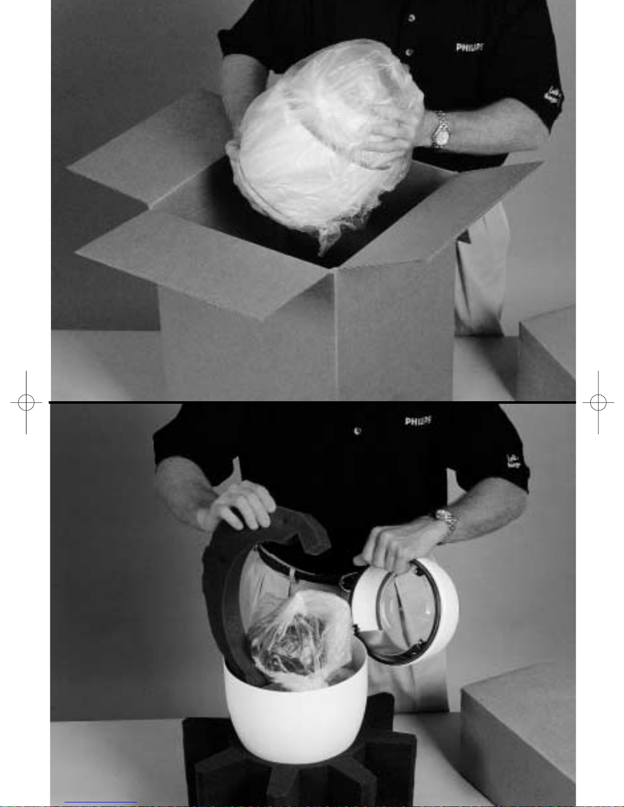
STEP
A1
Pendant/EnviroDome
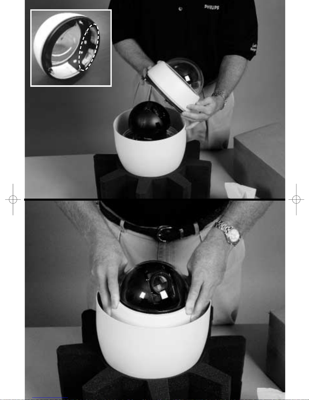
Carefully remove the G3 AutoDome®from the box.
The unit is shipped with the lower and upper housings
connected only by the safety cable. DO NOT
STRESS THE CABLE WHEN UNPACKING
THE AutoDome. Save all packing material, as it can
be used for setting up the camera and for transporting
the dome.
STEP
A2
Place the upper half of the G3 AutoDome into the star
shaped foam and remove all packing material. Make sure
to remove all debris that may interfere with the camera.
If an item appears to have been damaged in shipment,
replace it properly in its carton and notify the shipper. If
any items are missing, notify your Philips
Communication, Security & Imaging Sales
Representative or Customer Service Representative.
NOTE: Section A applies to the EnviroDome & Indoor Pendant.
Photos show the EnviroDome.
Installation Guide
6
STEP
A4
Press firmly on the edge of the lower half until
you feel the lower half mate with the upper
half. When properly mated, there should be
approximately 1/8 in (32 mm) gap all around
the Dome.
If you need to remove the lower half, a plastic
Dome key is provided.
STEP
A3
7
Remove the camera’s plastic lens cover.
If installing the EnviroDome model, a desiccant
bag and holder are included to reduce exposure to moisture. Ensure that the desiccant bag
is securely tucked into the ring of the lower
housing, as shown in the photo inset at right.
Align the ball studs in the lower half with the
clips in the connector end of the upper half.
The safety cable should prevent misalignment.
Installation Guide
Pendant/EnviroDome
8

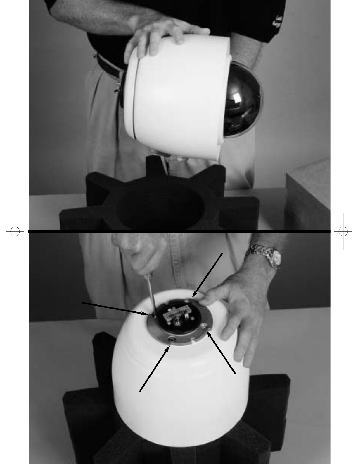
STEP
A5
CAMERA ADDRESSING
To use FastAddress, skip to step A10.
Otherwise, to manually set the switch address,
flip the dome into the star shaped foam so the
bubble side is down.
STEP
A6
Remove the 4 top screws as shown and lift the
top plate carefully off the dome. The cable is
approximately 5 cm (2 in) long, so remove
carefully from the PCB.
Remove the top plate cable (if necessary) from
the dome to access the address switch. Set
the address switch (as in Step A7) and make a
note of it.
9
Installation Guide
Pendant/EnviroDome
10
STEP
A7
If you are using RS-232 Communications:
The unit is shipped with the RS-232 Baud Rate
set to 9600.With the connector plate
removed, the baud rate can be changed with
the dip switch.
Switch 1: RS-232 Baud rate: Off = 9600,
On = 19.2K
STEP
A8
Reconnect the top plate cable. Replace the top
plate and gasket. Align the yellow dot on the
connector top with the dimple on the housing
and firmly tighten the four screws. Do not
overtighten.
11
Installation Guide
Pendant/EnviroDome
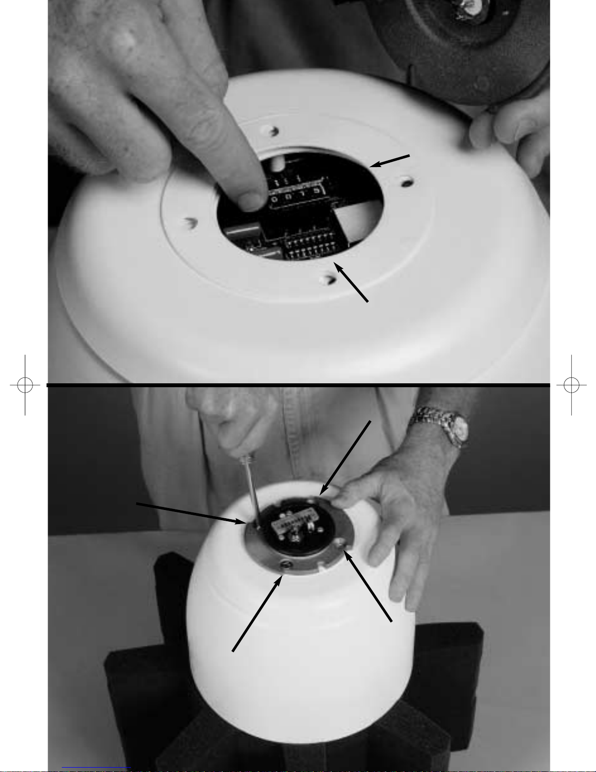
ADDRESS SWITCH
BAUD RATE DIP SWITCH
(RS232 ONLY)
SWITCH 1: RS-232 Baud rate:
Off = 9600, On = 19.2K
12
13
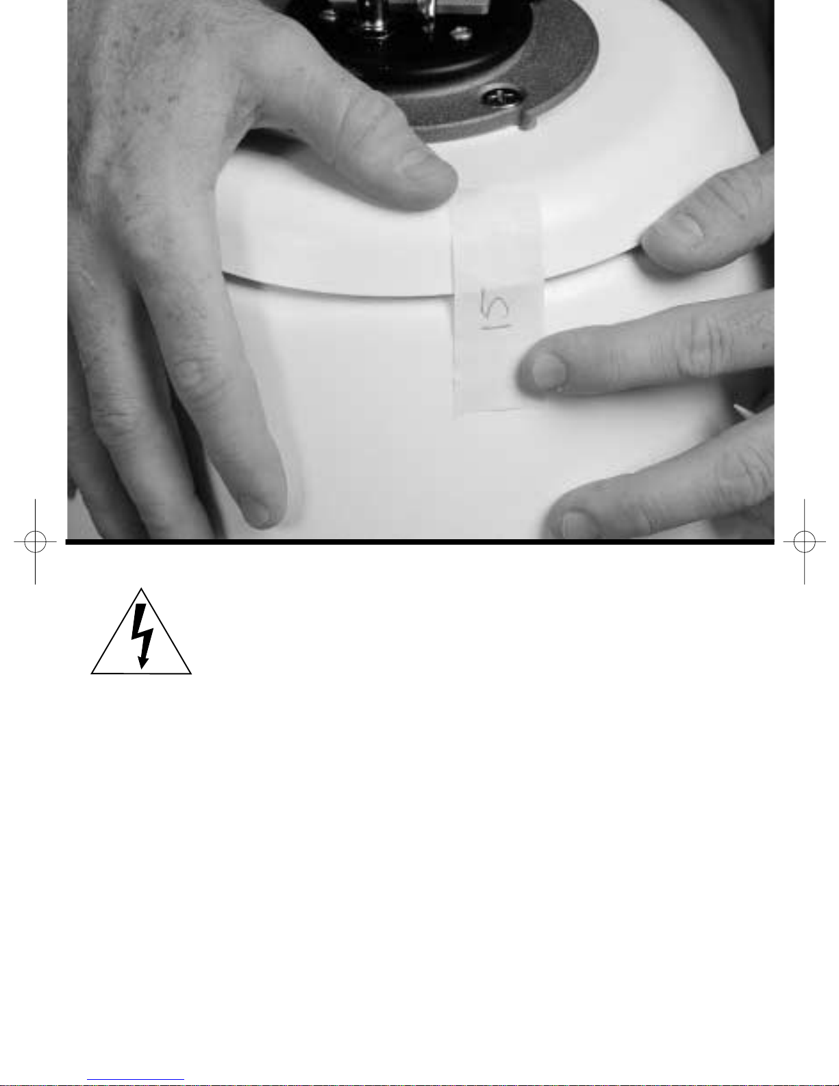
STEP
A9
Writing the address on masking tape and sticking it to the dome will help avoid confusion
when installing the dome.
The dome is now ready to be installed using an
appropriate G3 mount!
ATTENTION: Installation should
be performed by qualified service personnel only, in accordance with the
National Electrical Code or applicable
local codes. Refer to applicable installation section.
The G3 AutoDome can be mounted to a wall, mast
(pole), roof, pipe, or a corner mount.You must have
installed the appropriate mount before installing the
AutoDome. Each mount includes its own mounting
instructions.
Installation Guide
Pendant/EnviroDome
14
CAUTION: Mounts must be properly and securely mounted to a supporting structure capable of sustaining the unit
weight.* Use care when selecting mounting hardware (not
supplied) for installation. The mounting surface and unit's
weight should be carefully considered.
The following instructions reference a 120/230 VAC Pendant wall
plate installation mounted to an existing structure. The instructions
assume the safety cable, power, video, and control cables have already
been properly installed.
*Refer to mounting instructions.
 Loading...