

Philips G22K511, G25K512 Service Information
COLOUR
TELEVISION
S E R V I C E I N F O R M A T I O N F O R T H E
PHILIPS
G22K511
AND
G 2 2 K 5 1 1
G6 SINGLE STANDARD'
COLOUR TELEVISION
RECEIVERS
. •
c-es
C O M M B I N E D E L E C T R O N I C S E R V I C E S L I M I T E D
604 P UR LE Y WAY • W ADDON • CROYDON • CR9 4D R
TE LEPHON ES :
Spare part orders : 01-686 3831 General service enquiries : 01-688 7722
After business hours: Recorded messages on both lines Telex 262308
AUGUST, 19 69 (Please quote CES 739 when ordering further copies) CES 739

CONTENTS
TEXT
Section
Page No.
UNIT LOCATION
Unit
Page No.
A — INTRODUCTIO N
3
A — CONVERGENCE ASSEMBLY LAYOUT
17
B — SPECIFICATION
3
B — L.O.P.T. ASSEMBLIES—UPPER
18
C — RECEIVER NOTES
4
C — L.O.P.T. ASSEMBLIES—LOWER
18
D — 625-LINE V.H.F. RELAY OPERATION
5
D — T.B. PANEL—PRINT SIDE
20
E — SPECIALLY MOUNTED COMPONENTS
5
E — C.R.T. BASE PANEL—COMPONENT SIDE
21
F — MAIN TENANCE NO TES
6
F — CHROMA. PANEL—PRINT SIDE
22
G — L.O.P.T. ASSEMBLY
6-7
G — CENTRE CHASSIS WIRING
25
H —PRESET ADJUSTMENTS
9-10
H — TOP LEFT CHASSIS WIRING
25
- CONVERG EN CE
10-11
J — SUB-ASSEMBLIES WIRING
26
J — GREY SCALE TRACKING
12
K — LOWER CHASSIS WIRING
26
K — COLOUR DIFFERENCE OUTPUT
L — I.F. PANEL—COMPONENT SIDE
27
ADJUSTMENTS
12
L — I.F . ALIGNM ENT
12-14
EXPLANATION OF WIRING CODING
M — DECODER ALIGNMENT
14-15
N — INTEGRATED TUNER ASSEMBLY
32-35
On unit J, lead marked is connected to unit K
0 — SPARE PARTS LIST
37-43
and there marked . Similarly, on unit D, lead marked
is connected to unit E and there marked
ILLUSTRATIONS
Fig. No.
RECEIVER IDENTIFICATION
1 — SPRING RESISTOR R1073
If
2 — C ONVERG E N C E COVER 3 —
ASSEMBLY OF C.R.T. AND SHIELD 4 —
C. R.T. SHIEL D 5 — TR IM P LAN
6 — THI RD HARMONIC TUNI NG
7 — DEFLECTION ASSEMBLY
8 — CONVERGENCE PANEL
9 — TER MINATING PAD
10 — DAMPER/DETECTOR UNIT
11 — DETECTOR UNIT
12-15 RESPONSE CURVES
16 — BIAS NETWORK
17 — X-Y DISPLAYS
18 — BLOCK DIAGRAM
19 — CONVERGENCE ASSEMBLY WIRING
20 — L.O.P.T. ASSEMBLY—UPPER
21 — L.O.P.T. ASSEMBLY—LOWER
22 — L.O.P.T. PANEL
23 — TIME BASE PANEL—PRINT SIDE
Page No.
2
5
6
6
7
8
9
10
11
12
12
12
14
14
15
16
17
18
18
19
Fig. No.
24 — TIME BASE PANEL—COMPONENT SIDE
25 — C.R.T. BASE PANEL—COMPONENT SIDE
26 — C.R.T. BASE PANEL—PRIPANEL-PRINT
27 — CHROMA. PANEL—PRINT SIDE
28 — CHROMA. PANEL—COMPONENT SIDE
29 — CAN ASSEMBLIES—A TO F
30 — CHASSIS WIRING—CENTRE AND
TOP LEFT
31 — CHASSIS WIRING—LOWER, AND
SUB-ASSEMBLIES
32 — I.F. PANEL—COMPONENT SIDE
33 — I.F. PANEL—PRINT SIDE
34-36 VOLTAGE WAVEFORMS
37 — TUNER MECHANISM—EXPLODED
VIEW
38 — DRIVE GEAR SETTING
39 — TUNER—COMPONENT LAYOUT
40 — TUNER—CIRCUIT DIAGRAM
41 — CIRCUIT DIAGRAM—I.F., etc.
42 — CIRCUIT DIAGRAM—T.B., etc.
Page No.
21
21
21
22
23
24
25
26
27
28
29-31
32
33
34
35
In
pocket
Page One
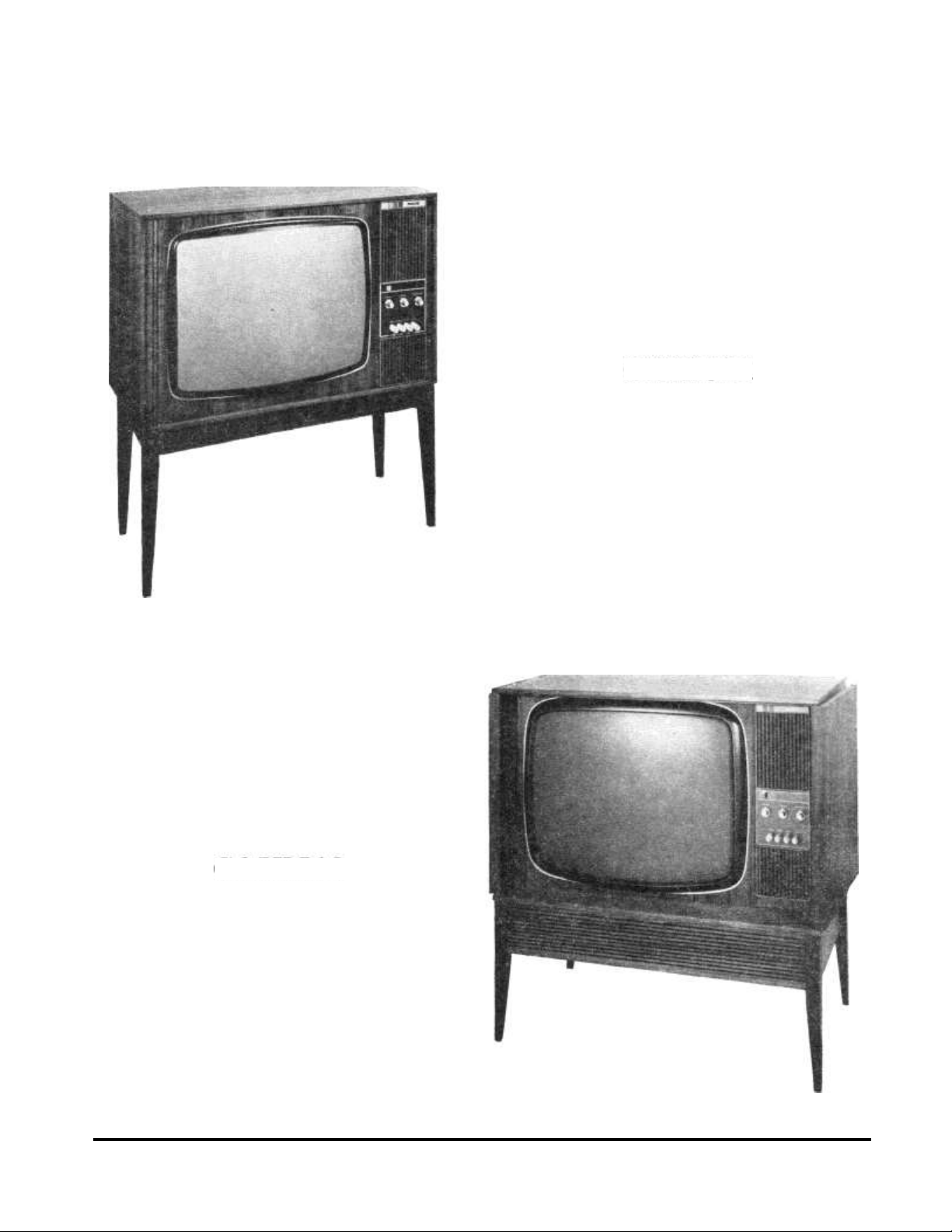
G22K511
G25K512
Page Two

A — INTRODUCTION
The G22K511 television receiver is designed for reception of both
colour and monochrome pictures on 625 lines. A 22" rectangular
shadow mask cathode ray tube is employed around which are
fitted a pair of degaussing coils. These automatically degauss the
tube each time the receiver is switched on. The main chassis is
mounted vertically at the rear of the receiver, and when servicing
is necessary, it can either be hinged backwards or removed completely. The tuner is a UHF/VHF integrated type, operated by
four push-buttons which can be set to receive any 625-line channel
on UHF or relay channel on VHF. By removing one screw, a part
of the front escutcheon comes away, revealing easy access to the
grey scale and dynamic convergence controls. This enables the
more difficult setting up to be done from the front of the receiver.
Special features include a fully pluggable I.F. panel to facilitate easy
servicing, and a new black level clamp circuit to ensure faithful
reproduction of low key scenes.
The G25K512 is a 'Deluxe' version of the above receiver employng a 25" push through cathode ray tube. Housed in a consolette
tyle cabinet and finished in teak veneers, it has two single doors
which are secured by ball catches when closed.
B — SPECIFICATION
Mains supply 240 volts a.c. only
Valves Type Function
V1706 A56-120X 22" Shadow-mask C.R.T.
or V1706 A63-120X 25" Shadow-mask C.R.T.
V2001 PFL200 Luminance output and sync. separator
V2002 EF80 Line sync. amplifier
V4001 PCF802 Line reactance and oscillator
V4002 ECC81 Field oscillator
V4003 PCC85 Field buffer/fly-back suppression
V4004 PL508 Field output
V5001 PL509 Line output
V5002 PY500 Boost diode
V5003 PD500 Shunt stabiliser
V5004 GY501 E.H.T. rectifier
V5005 EY51 Focus diode
V7001 EF183 1st chroma. amplifier
V7002 EF184 2nd chroma. amplifier
V7003 PCC85 Chroma. A.G.C./colour killer
V7005 PCF200 R-Y amplifier/clamp
V7006 PCF200 G-Y amplifier/clamp
V7007 PCF200 B-Y amplifier/clamp
V7008 EF184 Burst amplifier
V7009 PCF802 Reactance/reference oscillator
VA V7010 PCL86 A.F. amplifier/output
Semi- Type Function
conductors
T1321 AC128
T2140 BF194
T2141 BF194
T2142 BF196
T2143 BF196
T2144 BC148
T2145 BC148
T2146 BC148
T2147 BC148
T2624 BF197
T2755 BF173
T3401 BF180
T3402 BF182
T3403 BF183
T3495 BC108
T7011 BF195
T7012 BF195
T7013 BF194
T7014 BF194
T7015 BC107
X1101 BY127
X1102 BY127
X1103 BA148
X1104 BA148
X1105 BYX10
X1106 BA148
X1292 BA148
X1293 BA148
X1294 BA148
X2151 0A91
X2152 BA154
X2153 0A91
X2530 AA119
X2531 AA119
X2625 0A90
X2756 0A90
X3496 BZY88
X4140 BA148
X4141 BA148
X4142 BYX10
X7315 0A90
X7316 0A85
X7317 0A202
X7318 0A95
X7319 BA100
X7320 AA119
X7321 AA119
X7322 0A91
X7323 BA148
X7324
X7325 BA154
X7568 0A95
X7569 0A95
X7570 0A95
X7571 0A95
X7628 BAY38
X7629 BAY38
X7630 BAY38
X7631 BAY38
X7632 BAY38
X7655 0A95
X7656 0A95
Circuit protectors
Fuses Type
FS1107 3A
FS1108 Thermal
FS1109 250mA
FS1110 Thermal
FS1114 Thermal
Drop-off resistors
R2111 1.5K52
R4135 12052
Safety resistors
R4083 3.3K52
R7148 1052
R7151 1052
R7263 1ic52
R7293 18052
Spark gaps
SG10981
SG1099 f
E.H.T.
Loudspeaker
Sound output
Dimensions
G22K511
G25K512
Weight
G22K511
G25K512
li
Convergence clamp
1st sound I.F.
2nd sound I.F.
1st vision I.F.
2nd vision I.F.
Luminance phase splitter
Luminance A.G.C. amplifier
Black level clamp
Chroma. pre-amplifier
3rd vision I.F.
Chrominance amplifier
R.F. amplifier
Mixer
Oscillator
A.G.C. amplifier
B-Y pre-amplifier
R-Y pre-amplifier
}Bistable oscillator
Identification signal amplifier
Mains rectifier
Mains rectifier
L.T. supply rectifier L.T.
supply rectifier –ve supply
rectifier Supply for black
level clamp
}Auxiliary d.c. supply to C.R.T.
1
A.G.C. delay
Black level clamp
A.G.C. rectifier
1 F.M. ratio detector
Luminance demodulator
Chrominance demodulator
Tuner supply stabilisation
} Line discriminator
Fly-back pulse clipper
Chroma. noise clipper
}Burst keying
Burst blanking
Bias clamp
}PAL switch (180°)
Identification signal gate
Stabilised H.T. supply
4.43 MHz crystal
Beam current limiter
B-Y demodulator
R-Y demodulator
Anti-lock-out
Chroma. A.G.C. demodulator
Burst demodulator
Ref. oscillator A.G.C.
Ref. oscillator grid clamp
Location
Mains supply
Main H.T. supply
Field output
Main H.T. supply
Mains transformer
Luminance output
Field output stage
Line reactance stage 1st
chroma. amp. stage
2nd chroma. amp. stage
Burst amp. stage
A.F. output stage
C.R.T. base panel
25kV
6" x 4" elliptical, 5ohm
impedance 2.5 watts
Height Width Depth
(Inc. backplate)
28" 2W
31-i" 23"
861bs.
1291bs.
181'
33f"
(Inc. legs)
Page Three
C — RECEIVER NOTES
1. Mains supply voltage
This colour receiver has been designed to be used with a nominal
mains voltage of 240v. a.c. Engineers are advised that operating a
receiver on a mains supply which provides poor voltage regulation
(i.e., an isolation transformer rated at less than 500 watts) may
present difficulties in obtaining optimum convergence.
Note.—Once the receiver controls have been set-up, slight re-adjust-
ment may be necessary if the set is operated from a supply voltage
different from the initial setting-up voltage.
2. X-ray radiation warning
The voltages and currents on the cathode ray tube are higher in a
colour receiver than in a monochrome type, and as a result, the
X-rays produced will have a greater penetrating power and will
be present in larger quantities. In practice, this means that suitable
protection has to be built into a receiver in order to reduce the radiation hazard to an acceptable level. It is important that personnel
involved in installation and servicing should be well aware of any
possible dangers.
The radiation problems are confined to X-rays generated by two
sou r ces:
(a) The cathode ray tube
(b) The extra high tension generator
During the development of the `G6' colour television chassis,
special attention has been given to these points. With the backplate
removed no significant radiation is present, and therefore the maximum dose rate is much less than the accepted danger level. This low
level of radiation is due to :—
(i) The absorbing power of the glass in the cathode ray tube.
(ii) The C.R.T. metal cone shield provided for magnetic screening.
(iii) The metal screening enclosing the E.H.T. generator (L.O.P.T.
assembly).
Provision is made on the E.H.T. generator so that the unit is inoperative when the side cover of the screening can is removed. This
takes the form of an inter-lock switch disconnecting the H.T.
supply. On no account must this inter-lock be tampered with.
Line stabilisation control (R5040)
It is most important that this control is adjusted to the correct boost
voltage setting (see Adjustments). Any increase above this setting
will cause the E.H.T. voltage to rise, resulting in possible forward
X-ray radiation from the C.R.T. face.
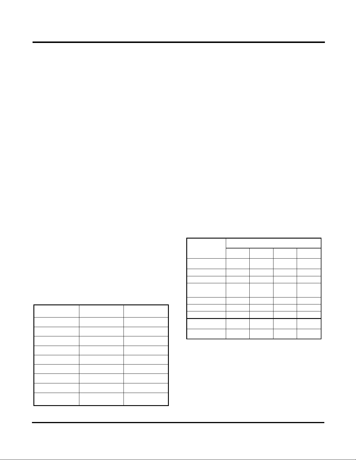
3. Colour coding of H.T. supply leads
In order to assist service engineers in identifying the various H.T.
supply leads to different parts of the receiver, a system of colour
coding these leads is used which is shown below.
Supply
Lead colour
Voltage
H.T.2
Red
+285v.
H.T.2 (fused)
Red/Brown
+285v.
H.T.3
Red/Orange
+250v.
H.T.4
Red/Yellow
+230v.
H.T.5
Red/Green
+220v.
H.T.6
Red/Blue
+220v.
H.T.7
Red/Grey
—120v. stab.
H.T.8
Black/Orange
+12v. stab.
H.T.9
Black/White
+18v.
4. Special trimming tool
A special star-shaped trimming tool is necessary for the alignment
of the tuner I.F. coil, and also for adjustment of certain other
cores. This trimming tool is available as part of the Philips
trimming tool kit 800/TX, and engineers are advised that any attempt
to adjust these cores with a non-standard tool may damage them.
5. Use of the circuit diagram
(a) The complete circuit of the `G6' single-standard colour tele-
vision receiver (less integrated tuner) has been drawn out on two
separate sheets accompanying this manual. The connecting leads
have been so arranged that the two halves of the circuit may be
permanently joined together with transparent adhesive tape if
required. H.T. points from the power supply circuits are shown
set in boxes, and an equivalent symbol is indicated at the particular
part of the circuit to which it is connected (see also note in colour
coding of H.T. leads—para. 3 above).
(b) For component identification on the circuit, a grid refe
system is used. This has been arranged so that each sheet may be
used either separately or joined together, the letters at the top of the
circuit running from A to S and the numbers at the side of each
diagram running down from 1 to 7. The grid location for all components has been included in the Spare Parts List.
Where it has been found impracticable to show direct connections
between various parts of the circuit, e.g. the line pulse feeds
from L5505 and L5524, a grid reference has been included to assist
in locating the appropriate circuit connections.
(c) In order to identify a particular component on the circuit
with its position in the receiver, a coding system for component
numbers is used. For instance, any component with a 2000 number
is located on the I.F. panel, and a component with a 5000 number
will be found in the line transformer assembly. The complete
coding system is as follows:
LOCA TIO N
Number
Val ves &
Sem icon .
Re sis tors
Ca paci tor s
Coils
Main chassis and sub.
ass embl ies
1100
1000-1100
1000-1100
1500
C.R .T. base panel
1700
1000
1000
1500
Co nv erg enc e u ni t
1200-1300
1200-1300
1200-1300
1600
Deflec tion, con vergence and degaussing
yokes
—
1700
1700
1700
I.F. Panel
2000
2000
2000
2000
In tegr ate d tu ner
3000
3000
3000
3000
Ti me B ase
4000
4000
4000
4000
Line t ran sfo rme r
ass embly
5000
5000
5000
5000
Ch roma . p anel
7000
7000
7000
7000
6. Connecting plugs and sockets
The plugs and sockets used for interconnecting assemblies are
colour coded to enable service engineers to identify where each is
fitted to the main chassis. This takes the form of a coloured ring
around the plug on the appropriate connection panel, and a
similarly coloured sleeve marker around the leads into the respective socket.
Note.—Sockets should never be removed from the plugs by pulling
on the leads, since this practice may lead to the pins within the
sockets being damaged.
Page Four
P lu g an d so ck et l oc ati on t able s
P lu g so ck et N o.
C ol ou r co di ng
Location
I
—
I. F. i npu t o n I. F. pane l
2
—
I.F . pa nel ( 5 le ads)
3
—
I.F . pa nel ( 6 le ads)
4
Red
Con verg ence plug on c entr e
cha ssis (up per)
5
Ye ll ow
Con verg ence plug on centr e
ch assi s ( lowe r)
6
—
Def lectio n coi l plu g on c entre
chas sis
7
—
Upp er p lug o n si de of L.O .P.T.
ass embl the
8
—
Low er p lug o n si de of L.O .P.T.
ass embl y
9
—
Deg auss ing c oil plug on l ower
chassis
P lu gg ed
c on ne ct io ns
L ea d co lo ur
L oc at io n
Pc!
Ri lll ack
Tu ner sup ply lea d
Pc2
Grey
Tu ne r A .G. C. le ad
Pc3
Black
Ea rth link bet ween ch roma . an d
I.F. panels
Pc4
Grey
Chr ominan ce si gnal f eed to
ch roma . p anel
Pc5
Sc reen ed
A. F. o utp ut o n I .F. pan el
Pc6
Brown
Lu mina nce out put on I .F. pan el
D — 625-LINE V.H.F. RELAY OPERATION
Ten channels have been allocated inside the V.H.F. T.V. bands
(I and III) for use on wired relay systems.
Conversion instructions
1. Tuner
With all the push buttons in the unlatched position, depress the
appropriate plastic knob at the rear of the tuner and rotate until
-
Nao indication on the end of the knob lines up with the required
,and and system. A label which is attached to the rear of the tuner
wvill assist in this setting-up procedure.
2. Operation
Depress the appropriate push-button and apply the 625-line relay
signal to the V.H.F. aerial socket. Using the receiver in the normal
way, tune for best picture definition, consistent with maximum
sound.
E — SPECIALLY MOUNTED COMPONENTS
The following information relates to the replacement of certain
components; it is very important that the methods described below
are carried out.
1. Drop-off resistors
122111 and R4135 are spaced from their printed panels on stand-
off solder tags. Should one of these resistors overheat for any reason,
such as an inter-electrode short-circuit occurring in a valve, the
solder on the tags will melt, allowing the component to fall away.
This provides a degree of protection to the panels and other
circuitry. Replacements should be made with Dubilier type
BTA 1 watt resistors, using ordinary '60/40' resin-cored solder.
The resistor must be mounted on the underside of the solder tags,
with the connecting wires placed straight under the tags and not
wrapped around them.
2. Ballast resistors
During manufacture, a high melting point solder is employed on
all connections to the supply ballast resistors R1052/R1053. It is
most essential that this grade of solder (e.g. Ersin Comsol
Alloy) is used with a high temperature soldering iron if this
component is replaced.
3. Thermal fuses FS1108 and FS1110
Two thermal fuses (FS1108 and FS1110) in the form of wire
springs, are soldered on R1052/R1053. Excessive heat dissipation
causes the solder to melt and the fuses to spring free. The fuses
must be refitted using '60/40' solder.
4. Thermal fuse FS1114
A thermal fuse FS1114 is fitted inside the mains transformer bobbin.
When this fuse blows, tin splashes may be deposited on its surrounding plastic shield. The faulty fuse, as well as the plastic
shield, should be withdrawn from the bobbin, and the tin splashes
removed from the shield. The shield should then be reinserted in the bobbin together with a new fuse.
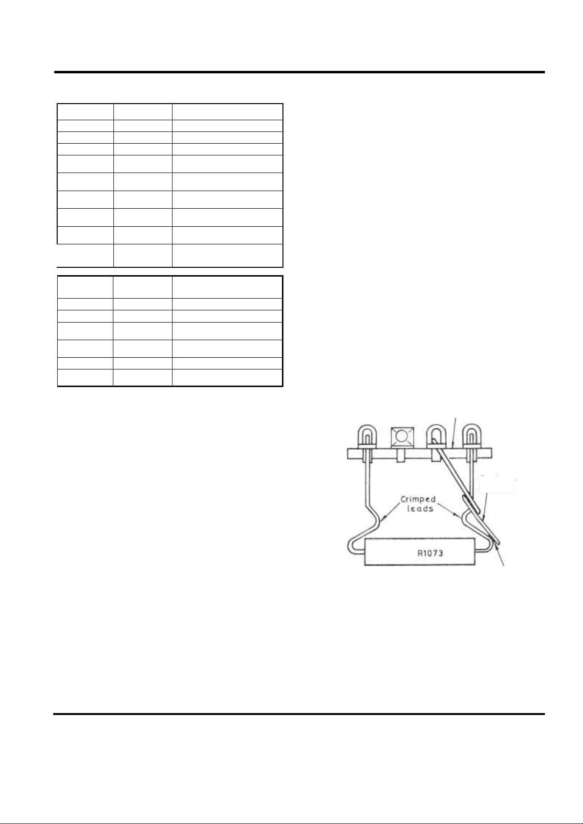
5. 'Spring resistor' R1073 (See Fig. 1)
A resistor R1073 and spring-off, mounted on a tag strip near the
mains transformer, are included to protect the line output stage
valves against certain fault conditions. The assembly forms a
thermal fuse with properties dependent upon the melting point of
the solder used to fix the spring-off to the resistor. When necessary
the spring-off wire must be soldered to the outside of the bend in
R1073 lead-out wire using ordinary '60/40' resin-cored solder.
Note.—If it is necessary to replace R1073 and/or spring-off, the
resistor should be carefully fitted across the two end tags of the
strip. The b1/4nt end of the spring-off should be fitted through the
second tag from one end of the strip, then turned approx. 45° to
the strip before being soldered to the outside of the crimped part
of R1073 lead-out wire.
(Top view) Ta g strip
Soldered
joint
SD3880
Fi g.
I. "S pri ng resisto r" assemb ly
6. Safety resistors R4083, R7148, R7151, R7263 and R7293
The safety resistors listed above are designed to act as fuses when
their rated dissipation is exceeded. In the event of a fault causing
any one of these components to become open-circuit, it is most
important that they are replaced with a similar type (see Spare
Parts List) and that they are spaced approximately i" from the
printed panel by crimping the connecting leads.
s
Spring off wire
Page Five
 Loading...