

Philips FWM-997-X, FWM-997 Service Manual
MP3 Mini Hi-Fi System
FWM997X
/78
FWM997
/55
CONTENTS
Technical specification ..................................................................1-2
Service measurement setup..........................................................1-3
Service aids .................................................................................1-4
Instructions on CD playability ................................................2-1..2-2
Disassembly diagram............ ................................................3-1..3-2
Block diagram ................................................................................4-1
Wiring diagram ..............................................................................4-2
Main board
Circuit diagram ..................................................................5-1..5-2
Layout diagram ..................................................................5-3..5-4
AMP board
Circuit diagram .........................................................................6-1
Layout diagram ..................................................................6-2..6-3
Front board
Circuit diagram .........................................................................7-1
Layout diagram ..................................................................7-2..7-3
MCU board
Circuit diagram .........................................................................8-1
Layout diagram ..................................................................8-2..8-3
CD Board
Circuit diagram. ........................................................................9-1
Layout diagram ..................................................................9-2..9-3
Sub Power Board (it is not repaired,diagram for referrence only)
Circuit diagram. ......................................................................10-1
Layout diagram .......................................................................10-1
Sub AMP Board (it is not repaired,diagram for referrence only)
Layout diagram ....................................................................... 11-1
Sub SW Board (it is not repaired,diagram for referrence only)
Layout diagram .......................................................................12-1
Exploded view diagram ...............................................................13-1
Mechanical parts list ...........................................................13-2..13-3
Electrical parts list...............................................................14-1..14-2
©
Copyright 2009 Philips Consumer Electronics B.V. Eindhoven, The Netherlands
All rights reserved. No part of this publication may be reproduced, stored in a retrieval
system or transmitted, in any form or by any means, electronic, mechanical, photocopying,
or otherwise without the prior permission of Philips.
Published by LX 0903 Service Audio Subject to modification
Version 1.0
3141 785 33280

TECHNICAL SPECIFICATION
1 - 2
AMPLIFIER
RMS output power
Total output power ............................... 800 W RMS
Signal-to-noise ratio .......................... 67 dB A (IEC)
Frequency response .......................... 60 – 16000 Hz
Input sensitivity
AUX ................................................. 1500mV/2000mV
Output
Speakers .................................................................... 3 Ω
(1) (3 Ω, 1 kHz, 10%THD)
CD/MP3-CD PLAYER
Number of programmable tracks ......................... 40
Frequency response ............. 60 – 16000 Hz -3dB
Signal-to-noise ratio ....................................... 75 dB A
Channel separation .......................... 50 dB (1 kHz)
Total harmonic distor tion ................................. < 1.5%
MPEG 1 Layer 3 (MP3-CD) .......... MPEG AUDIO
MP3-CD bit rate ....................................... 32-256 kbps
(128 kbps advised)
Sampling frequencies ....................... 32, 44.1, 48 kHz
TUNER
FM wave range ................................... 87.5 – 108 MHz
AM wave range (9 kHz) ............... 531 – 1602 kHz
AM wave range (10 kHz)............. 530 – 1700 kHz
Tuning grid ............................................................ 9/10 kHz
Number of presets ........................................................ 40
Antenna
FM ....................................................................... 75 Ω wire
AM .............................................................. Loop antenna
USB PLAYER
USB ................................................................... 12Mb/s,V1.1
......................................... support MP3 and WMA files
Number of albums/folders ................. maximum 99
Number of tracks/titles ...................... maximum 999
FRONT SPEAKERS
System 4-way; double port bass reflex
Impedance ............................................................... 2 x 6 Ω
Woofer ................................................................... 2 x 5.25”
Tweeter................................................................... 2 x 1.75”
Output power ........................2 x (100 W+ 100 W)
Dimensions (w x h x d) . 225 x 430 x 275 (mm)
Weight .......................................................... 4.928 kg each
REAR SPEAKERS
System full range satellite
Impedance ....................................................................... 3 Ω
Speaker driver ........................................... 4” + 4” (fake)
Frequency response ............................ 150Hz-16KHz
Output power ................................................ 2 x 100 W
Dimensions (w x h x d) ....... 142.5 x 345 x 171.3
Weight .............................................................. 2.1 kg each
SUBWOOFER
AC Power ...........................110 – 127 / 220 – 240 V;
.......................................................50/60 Hz, Switchable
Power Consumption
Active ........................................................................100 W
Impedance ........................................................................ 6 Ω
Subwoofer driver ............................................................. 8”
Output power .........................................................200 W
Dimensions (w x h x d)..... 274 x 430 x 342.3 (mm)
Weight ......................................................................... 11.2 kg
GENERAL
Material/finish ................................... Polystyrene/Metal
AC Power (for the main unit) .......................................
.............................................. 110 – 127 / 220 – 240 V;
.......................................................50/60 Hz, Switchable
Power Consumption
Active .......................................................................... 90 W
Standby ..................................................................≤ 20 W
Dimensions (w x h x d) .. 265 x 345 x 382 (mm)
Weight (without speakers) ........................... 8.671 kg
Specifications and external appearance are
subject to change without notice.
e
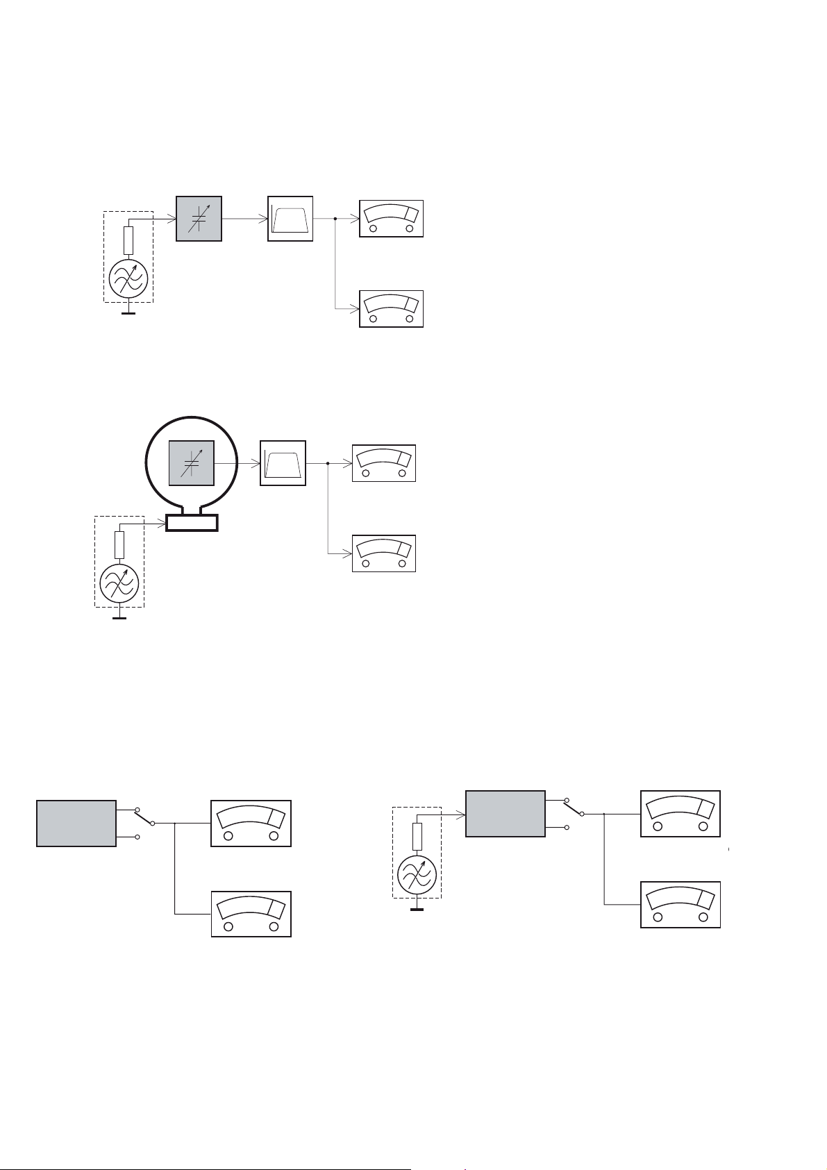
MEASUREMENT SETUP
Tuner FM
1-3
Bandpass
LF Voltmeter
e.g. PM2534
RF Generator
e.g. PM5326
DUT
250Hz-15kHz
e.g. 7122 707 48001
Ri=50:
S/N and distortion meter
e.g. Sound Technology ST1700B
Use a bandpass filter to eliminate hum (50Hz, 100Hz) and disturbance from the pilottone (19kHz, 38kHz).
Tuner AM (MW,LW)
RF Generator
e.g. PM5326
Ri=50:
DUT
Frame aerial
e.g. 7122 707 89001
Bandpass
250Hz-15kHz
e.g. 7122 707 48001
LF Voltmeter
e.g. PM2534
S/N and distortion meter
e.g. Sound Technology ST1700B
To avoid atmospheric interference all AM-measurements have to be carried out in a Faraday´s cage.
Use a bandpass filter (or at least a high pass filter with 250Hz) to eliminate hum (50Hz, 100Hz).
CD
Use Audio Signal Disc
(replaces test disc 3)
DUT
L
R
SBC429 4822 397 30184
S/N and distortion meter
e.g. Sound Technology ST1700B
LEVEL METER
e.g. Sennheiser UPM550
-
Recorder
Use Universal Test Cassette CrO2 SBC419 4822 397 30069
or Universal Test Cassette
LF Generator
e.g. PM5110
Fe SBC420 4822 397 30071
DUT
L
R
S/N and distortion met
e.g. Sound Technology ST170
LEVEL METER
e.g. Sennheiser UPM550
with FF-filter
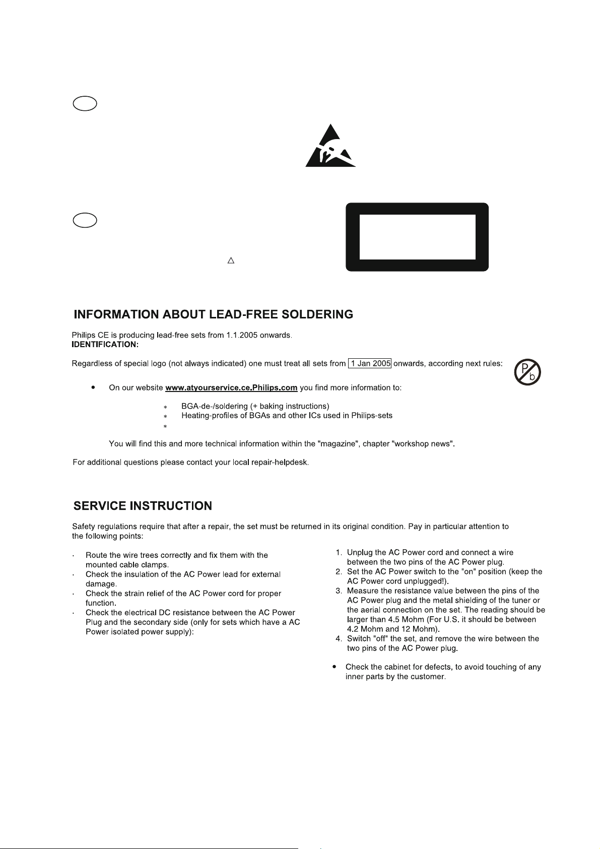
SERVICE AIDS
1-4
GB
All ICs and many other semi-conductors are
susceptible to electrostatic discharges (ESD).
Careless handling during repair can reduce life
drastically.
When repairing, make sure that you are
connected with the same potential as the mass
of the set via a wrist wrap with resistance.
Keep components and tools also at this
potential.
WARNING
GB
Safety regulations require that the set be restored to its original
condition and that parts which are identical with those specified,
be used
Safety components are marked by the symbol
!
.
ESD
CLASS 1
LASER PRODUCT
Lead free
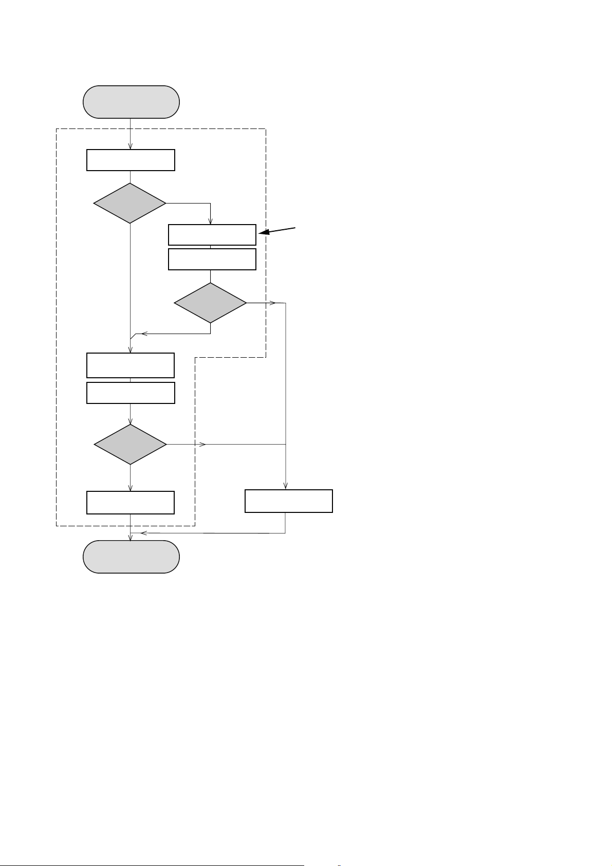
INSTRUCTIONS ON CD PLAYABILITY
Customer complaint
"CD related problem"
Set remains closed!
check playability
1
2 - 1
playability
ok ?
Y
Play a CD
for at least 10 minutes
check playability
playability
ok ?
Y
N
"fast" lens cleaning
check playability
playability
ok ?
N
3
N
Y
For flap loaders (= access to CD drive possible)
cleaning method
4 is recommended
add Info for customer
"SET OK"
2
return set
1 - 4 For description - see following pages
Exchange CDM
INSTRUCTIONS ON CD PLAYABILITY
2 - 2
1
PLAYABILITY CHECK
For sets which are compatible with CD-RW discs
use CD-RW Printed Audio Disc....................7104 099 96611
TR 3 (Fingerprint)
TR 8 (600µ Black dot) maximum at 01:00
• playback of these two tracks without audible disturbance
playing time for: Fingerprint
Black dot from 00:50 to 01:10
• jump forward/backward (search) within a reasonable time
For all other sets
use CD-DA SBC 444A..................................4822 397 30245
TR 14 (600µ Black dot) maximum at 01:15
TR 19 (Fingerprint)
TR 10 (1000µ wedge)
• playback of all these tracks without audible disturbance
playing time for: 1000µ wedge 10seconds
Fingerprint 10seconds
Black dot from 01:05 to 01:25
• jump forward/backward (search) within a reasonable time
10seconds
4
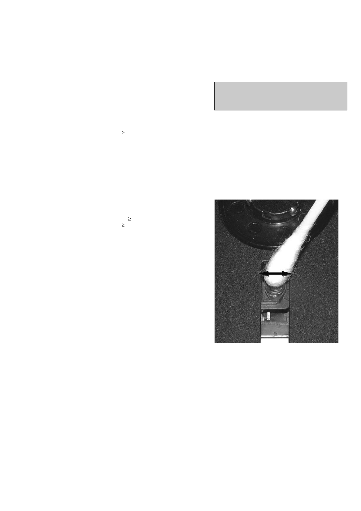
LIQUID LENS CLEANING
Before touching the lens it is advised to clean the
surface of the lens by blowing clean air over it.
This to avoid that little particles make scratches on
the lens.
Because the material of the lens is synthetic and coated
with a special anti-reflectivity layer, cleaning must be done
with a non-aggressive cleaning fluid. It is advised to use
“Cleaning Solvent
The actuator is a very precise mechanical component and
may not be damaged in order to guarantee its full function.
Clean the lens gently (don’t press too hard) with a soft and
clean cotton bud moistened with the special lens cleaner.
The direction of cleaning must be in the way as indicated in
the picture below.
2
CUSTOMER INFORMATION
It is proposed to add an addendum sheet to the set which
informs the customer that the set has been checked
carefully - but no fault was found.
The problem was obviously caused by a scratched, dirty or
copy-protected CD. In case problems remain, the customer
is requested to contact the workshop directly.
The lens cleaning (method 3) should be mentioned in the
addendum sheet.
The final wording in national language as well as the printing
is under responsibility of the Regional Service Organizations.
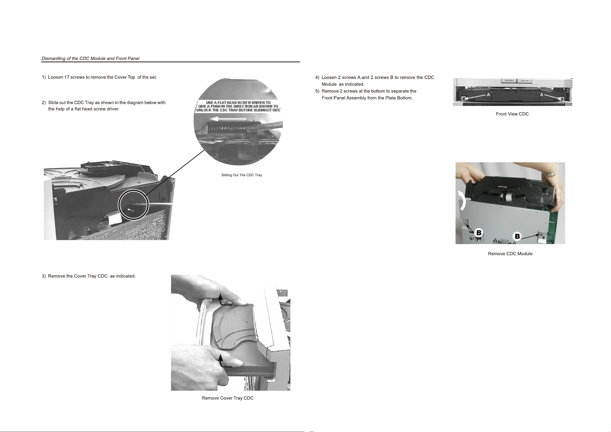
DISASSEMBLY DIAGRAM VIEW
PART 1
3 - 1
3 - 1
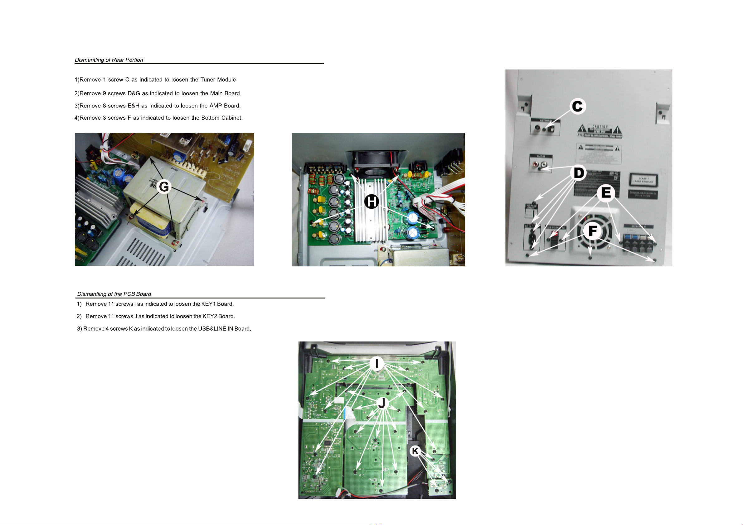
DISASSEMBLY DIAGRAM VIEW
PART 2
3 - 2
3 - 2
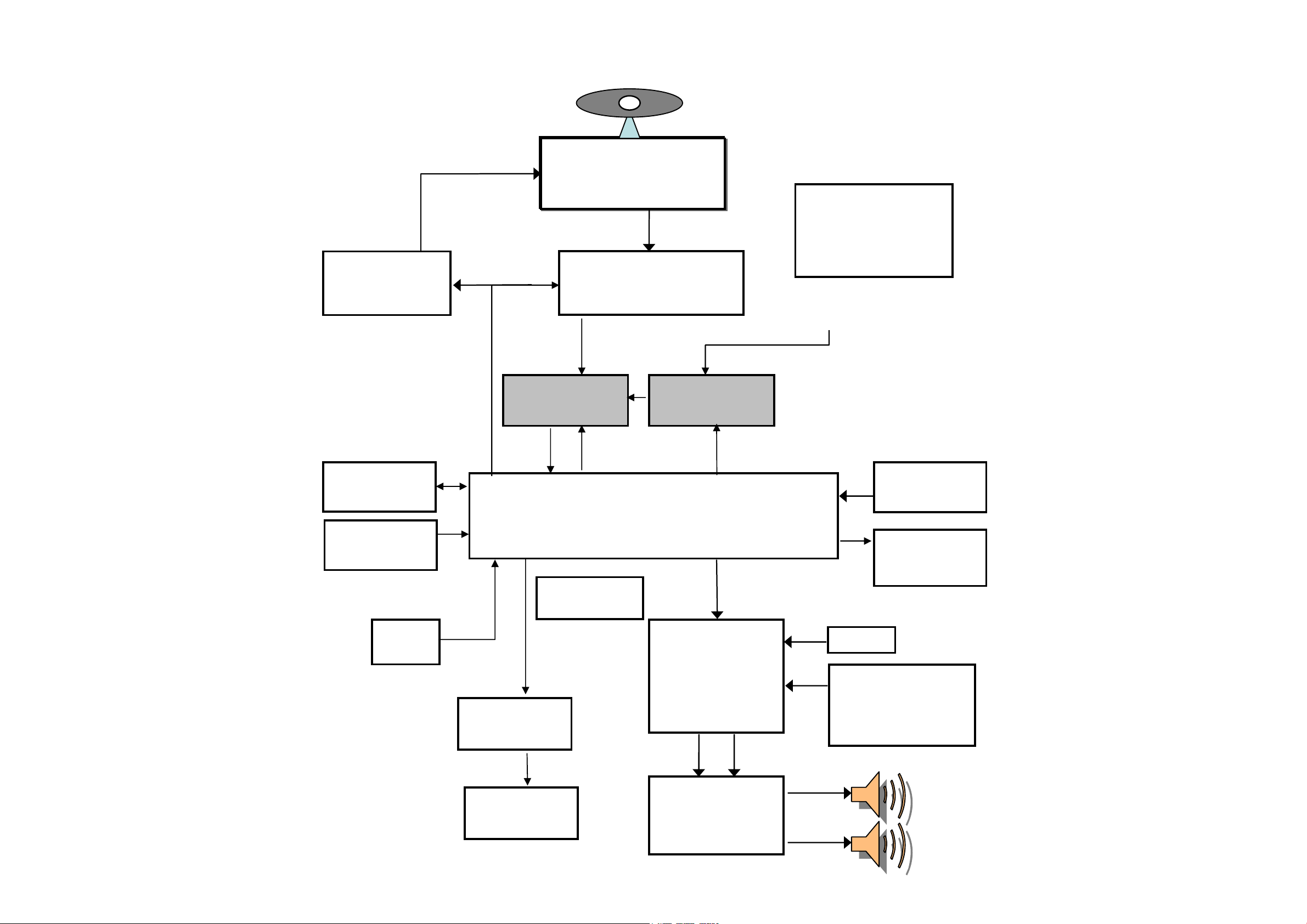
3CDC CD Loader
PICK-UP MECHA
SANYO : DA-11VF
4 CH
MOTOR DRIVER
(BA5826)
ROHM
RF AMP+SSP+DSP
(BU9543)
PLL Tuner
(SANYO
LC72131+TA1823
or Panasonic TM10)
MCS LOGIC BX8800
MP3/WMA En/De + MCU +USB/CARD
SOUND CONTROL
SW+VOL+EQ
(TDA7468 or
/PT2314)
POWER AMP
TDA8920
AUX
DISPLAY
VFD
USB/SD
MMC
NOR FLASH
SST39VF400A
SDRAM
16Mbit
Port Expander
74HC4094
VFD DRIVER
PT6315
Spectrum
analyzers
LED controller
for Light Box
(May use)
MUX
74VC157
ADC
CE2632
Karaoke
( use standard
FWM582 Karaoke
board)
SET BLOCK DIAGRAM
4 - 1 4 - 1
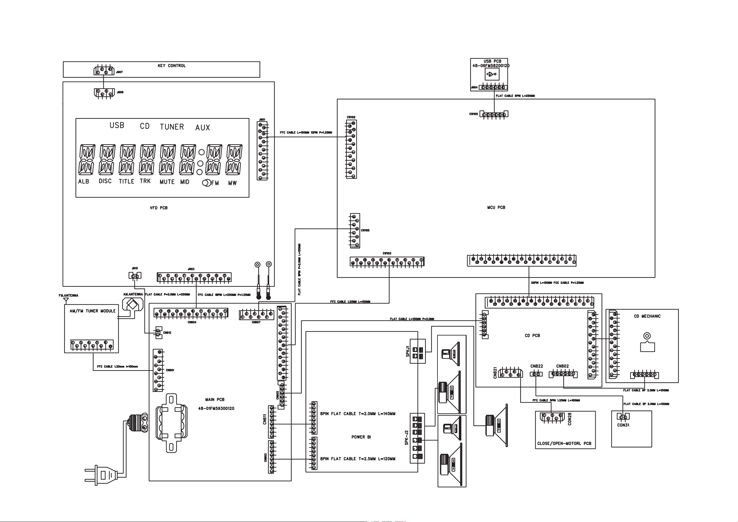
SET WIRING DIAGRAM
4 - 2 4- 2
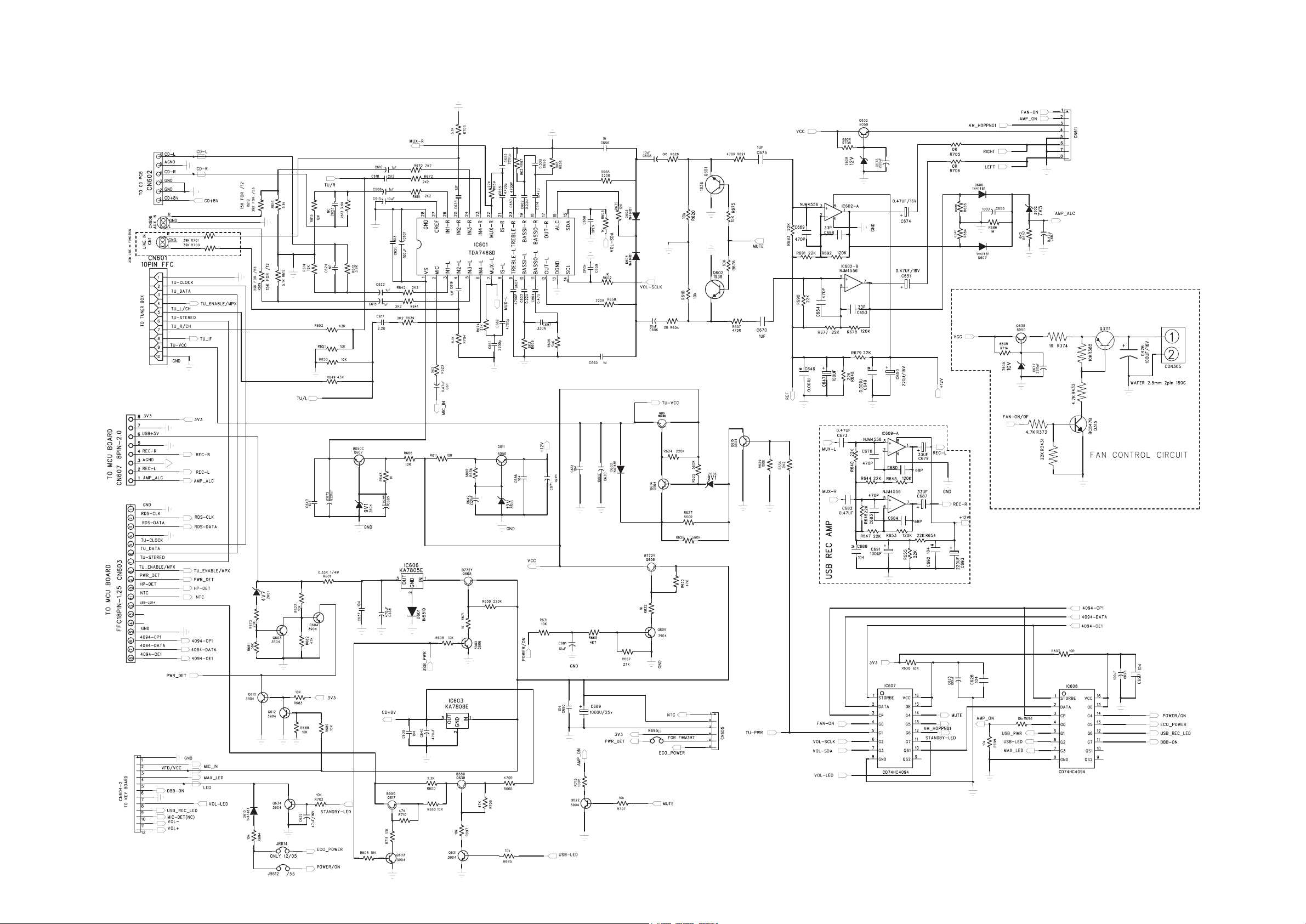
CIRCUIT DIAGRAM - MAIN BOARD
PART 1
5 - 15 - 1
 Loading...