

Philips EH313L User Manual
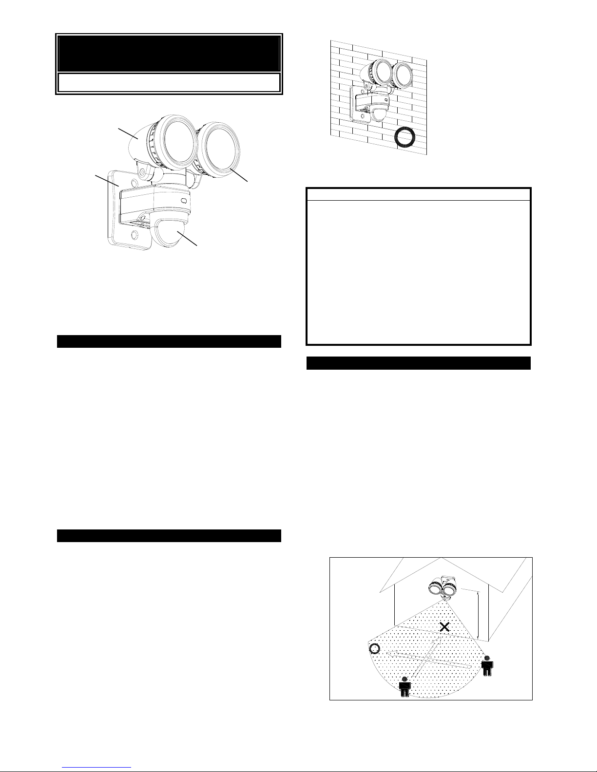
PHILIPS EH313L
7.5W x 2 LED FLOODLIGHT
LED Light
Lampshade
Wall Box
PIR (Motion Sensor)
INTRODUCTION
This 7.5W x 2 LED FLOODLIGHT is a unique indoor or
outdoor lighting system for your home or business place:
1. Prior to normal operation, test the light no matter in
the daytime or nighttime.
2. Determine how long the light will be on after motion
is detected.
3. Manual override feature enables the light to stay on
continuously both day and night.
4. Two adjustable lights allow you to provide the
optimum lighting coverage.
Note: Read this entire manual before you start to
install the system.
SAFETY PRECAUTIONS
DO NOT install this fitting when it is raining.
DO isolate the power supply during installation or
maintenance.
DO ensure that the power supply circuit is protected
by a 16 amp circuit breaker or suitable equivalent
fuse.
The fixing screw should not be removed after
installation. Secure the connection of the light
head assembly and motion sensor to the base, so
as to avoid any unsteadiness.
The unit can be installed vertically, not horizontally
as shown in the below drawing. (FIGURE 1)
Wall Mount Recommended (FIGURE 1)
IMPORTANT
Installation must be performed by skilled technicians
who are informed about the standards and technical
requirements of the appliance and its proper
installation.
Check your local codes as they apply to your situation.
If the house wiring is of aluminum, consult with an
electrician about proper wiring methods.
Before proceeding with the installation, TURN OFF
THE POWER TO THE LIGHTING CIRCUIT AT THE
CIRCUIT BREAKER OR FUSE BOX TO AVOID
ELECTRICAL SHOCK.
CHOOSING A MOUNTING LOCATION
For safety and the best results, fix the unit on a solid
wall, 2.5m above the ground.
For outdoor installation, a location under eaves is
preferable.
Avoid aiming the motion sensor at pools, heating
vents, air conditioners or objects which may change
temperature rapidly.
Do not allow sunlight to fall directly on the front of
unit.
Try to avoid pointing the unit at trees or shrubs or
where the motion of pets may be detected.
The motion sensor is more sensitive to objects
moving across its field of view. It is less sensitive
to objects moving directly towards the sensor head.
(FIGURE 2)
FIGURE 2
2m
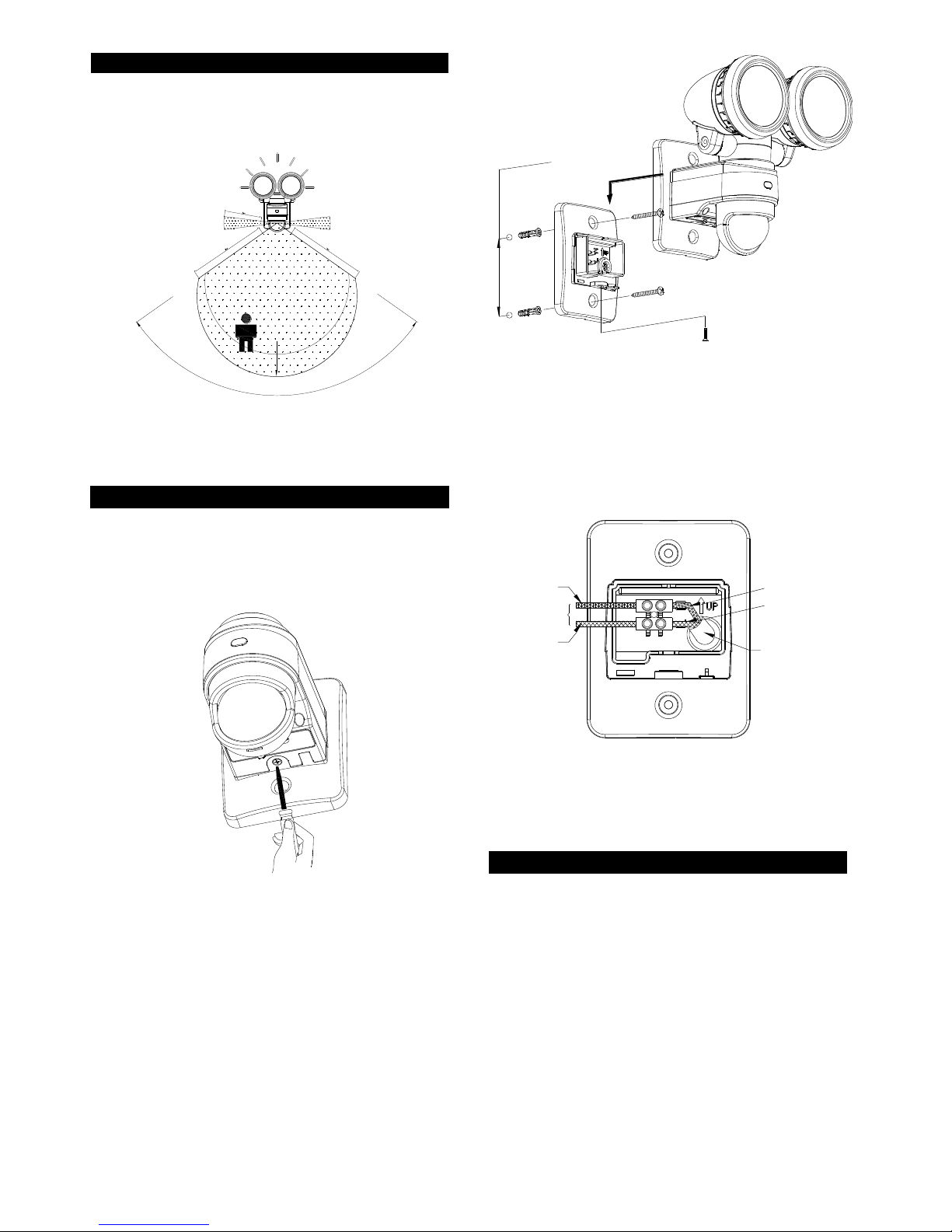
INSTALLATION
A drill and a screwdriver are needed for installation.
Select a location for the unit based on the coverage
angles shown in FIGURE 3.
180°
12m
110°
UNIT(m)
COVERAGE ANGLES
FIGURE 3
WIRING INSTRUCTION
(1) Switch off the power source.
(2) Detach the wall box by unscrewing the screw
adjacent to the control knobs (retain the screw for
later use). (FIGURE 4)
FIGURE 4
(3) Use a screwdriver to break a small hole on the cable
gasket, enabling the power cord to enter the wall
box.
(4) Route the power cord through the cable gasket.
(5) Determine the proper location to mount the light.
Use the wall box as a template to mark the fixing
holes on the wall. Drill the holes and insert the
plastic wall plugs supplied. Fix the wall box using
two screws provided. (FIGURE 5)
m
5.38
m
FIGURE 5
(6) Strip approximately 6-8mm insulating part of the
wires from the power cord.
(7) Connect the BROWN wire (Live wire) to the terminal
block “L” mark.
Connect the BLUE wire (Neutral wire) to the
terminal block “N” mark. (FIGURE 6)
TO LAMP
LIVE
NEUTRAL
AC POWER
BROWN
BLUE
FIGURE 6
(8) Replace the unit to the wall box by fastening the
screw retained.
ADJUST ANGLE
The lights can be adjusted up to 45° leftward and
rightward respectively; the PIR sensor can be adjusted
90° leftward and 90° rightward. (FIGURE 7a)
 Loading...