

Philips dynalite DTS900, dynalite DTS900M Installation Manual

features
dimensions
DTS900
DTS900M
DTS900 & DTS900M
Temperature Sensor
Installation Manual
Wide measurement range - 0º to 50ºC, accuracy +/- 1ºC
Available with or without user adjustable knob
Status LED - Indicates Heating, Cooling, Idle modes
Many Adjustable Parameters - Including top and bottom set
points, hysteresis, on and off timers
1 x RS485 DyNet Port - Available on a 5 way screw terminal
strip
Powerful Internal PLC - Custom scripts can be written to
provide process control based on conditional logic and
protocol translation between Dynalite’s DyNet and other
protocols
Powered from the DyNet Network – No need for an
external power supply
Read Instructions – We recommend that you read this
Instruction Manual prior to commencement of installation.
Special Programming – This device will only operate in basic
modes unless programmed via a computer. If programming is
required, contact your local agent for details.
Installation Location – Install on a vertical surface in a dry
location, at chest height.
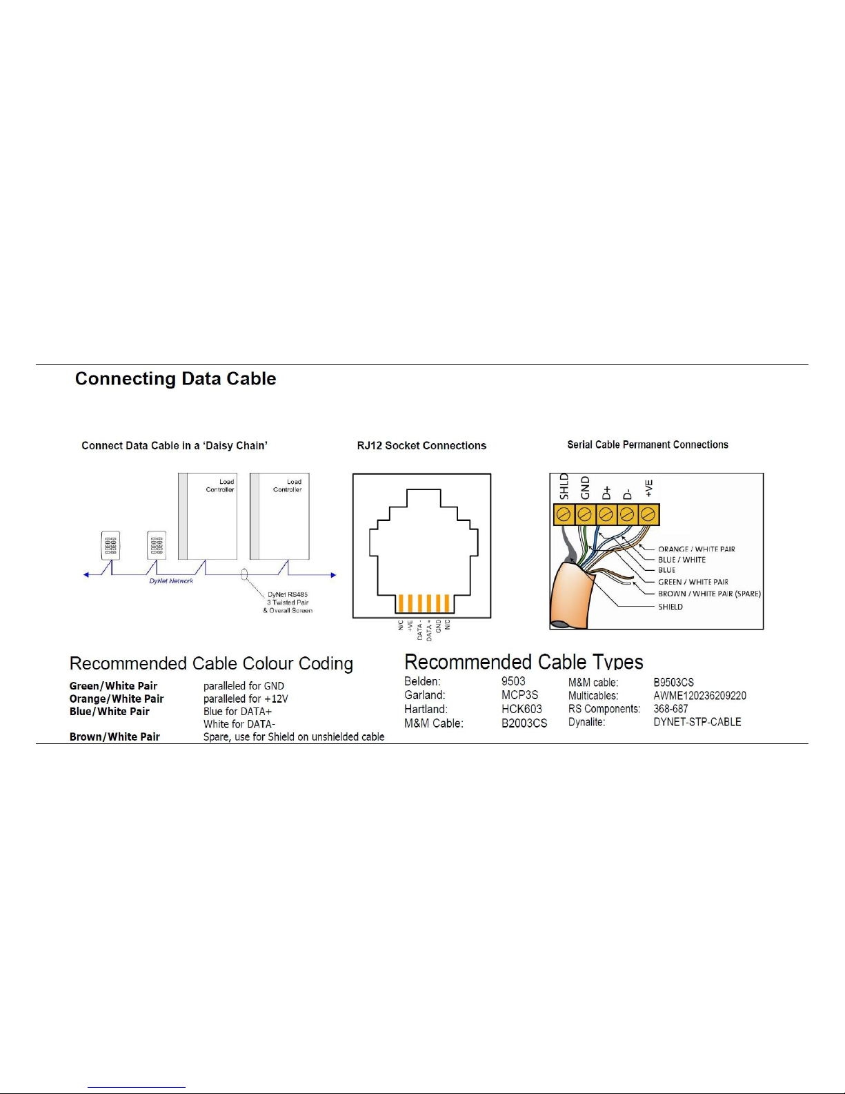
RS485 Data Cable – Use screened, stranded RS485 data cable
with three twisted pairs. Segregate from mains cables by 300mm
minimum. Connect devices in a ‘daisy chain’. A data cable that is
connected to an energised device is live. Do not cut or terminate
live data cables.
important notes
installation steps
product specifications
1. Select a suitable location, which should be a vertical surface such as a wall at approximately 1.5 meters height
from the floor. Do not install the DTS900 where it will be affected by:
* Drafts, or dead spots behind doors or in corners.
* Hot or cold air from ducts.
* Radiant heat from sun or appliances.
* Concealed pipes and chimneys.
* Unheated or uncooled areas behind the DTS900, such as an outside wall.
2. On the front cover remove the screw cover if DTS900 or knob if DTS900M and remove the front cover retaining
screw. Remove the front cover then mount the base to the wall using the 2 screws provided.
3. Connect the RS485 cable to the DyNet 5 way terminal strip. Note that this device consumes 20mA of power from
the DyNet network.
4. Replace the front cover screw and plug / knob.
Supply: 9 - 16V DC @ 20 mA from the DyNet network
Control IO: 1 x RS485 unterminated DyNet serial port, consisting of 1 x 5 way terminal strip
Measurement Range: 0º to 50ºC, accuracy +/- 1ºC
User Controls: - LED indicator: Blue = Cool, Violet = Idle, Red = Heat
- Temperature set point knob (DTS900M only)
Software Parameters: - Current temperature - read only
- Low Setpoint - adjustable 0º to 50º
- Low Setpoint Max On / Off Time
- High Setpoint - adjustable 0º to 50º
- High setpoint Max On / Off Time
- Hysteresis - adjustable +/- 0º to 5º
Compliance: CE, C-Tick
Operating Environment: 0º to 50ºC ambient temperature, 0% to 95% RH non condensing
Construction: ABS plastic wall mount enclosure
Dimensions: H 71mm x W 71mm x D 25mm
Weight: 0.11Kg
DTS900 & DTS900M Instruction Manual Rev D Specifications subject to change without notice
Dynalite manufactured by WMGD Pty Ltd (ABN 33 097 246 921) Unit 6, 691 Gardeners Road Mascot NSW 2020 Australia Tel: +61 2 8338 9899 Fax: +61 2 8338 9333
E-Mail: dynalite.info@philips.com Web: Philips.com/dynalite
connecting data cable
 Loading...