

Page 1
DVR1 Series
Digital Video Recorders
Philips
Communication,
Security & Imaging
Addendum
Eng
Page 2

2
Page 3

3
1 REO QUICK INSTALL GUIDE ..................................................................................................................4
1.1 Introduction ........................................................................................................................................................4
1.2 Required Software Version ..................................................................................................................................4
1.3 Installation ..........................................................................................................................................................4
1.3.1 Connection of Audio/Video Cable (A/V cable) ..............................................................................................................4
1.3.2 Connection of Alarm Contact ......................................................................................................................................4
1.4 Programming the REO System Monitor..............................................................................................................5
1.5 Programming the DVR1......................................................................................................................................5
1.6 Remote Viewing Considerations..........................................................................................................................5
2 INSTALLATION GUIDE FOR THE COMBINED PHILIPS MULTIPLEXER,
INTUIKEY KEYBOARD & DVR1 SERIES SYSTEM ................................................................................6
2.1 Overview ............................................................................................................................................................6
2.2 Required Software Version ..................................................................................................................................6
2.3 Installation ..........................................................................................................................................................6
2.4 DVR1 Keyboard Menus ......................................................................................................................................7
2.4.1 DVR1 Controls Menu ................................................................................................................................................7
2.4.2 DVR1 Playback Conrols Menu ....................................................................................................................................8
3 RS-232 REMOTE PROTOCOL ..................................................................................................................9
3.1 Supported Command Sequences..........................................................................................................................9
3.2 Setting the Clock ................................................................................................................................................9
For additional information or to speak to a representative,
please contact the Philips Communication, Security &
Imaging location nearest you:
The Americas: 1 800 326 3270
Europe & Middle East: +31 40 278 1222
Asia Pacific Region: +65 350 1859
or visit our Web site at www.philipscsi.com.
Page 4
4
1 REO QUICK INSTALL GUIDE
1.1 Introduction
This guide provides the steps necessary to install the DVR1 in combination with a REO Multiplexer or REO Switcher Monitor. If you
are not familiar with the operations of the DVR1 and the REO Monitor, refer to the corresponding instruction manuals.
1.2 Required Software Version
Ensure that the DVR1 and REO monitor’s software version is equal to or higher than noted below.
1.3 Installation
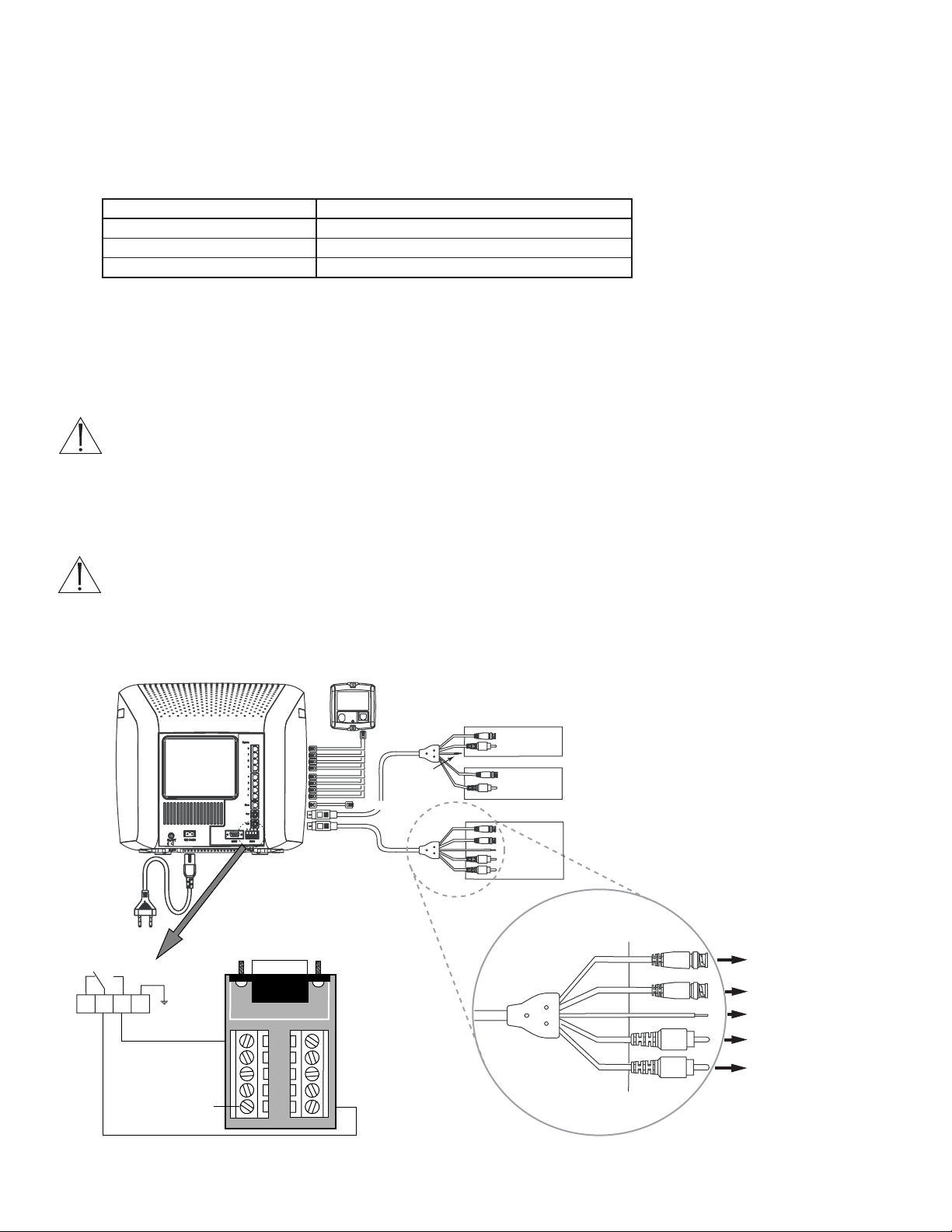
1.3.1 Connection of Audio/Video Cable (A/V Cable)
To record camera images, the REO VCR In/Output allows connection of the DVR1. Connect the Mini Din plug to the VCR
connector of the REO System Monitor.
1. Connect the BNC connectors to the VIDEO IN and VIDEO OUT of the DVR1.
ATTENTION:
VIDEO IN of the A/V cable must be connected to VIDEO OUT of the DVR1.
VIDEO OUT of the A/V cable must be connected to VIDEO IN of the DVR1.
2. Connect the black VEXT cable (located in the A/V cable) to the VEXT-pulse output of the DVR1 (Pin 5 of Accessories port) for
proper synchronization between the System Monitor and DVR1.
3. If the DVR1 also has audio recording capabilities, connect the RCA connectors to AUDIO IN and AUDIO OUT of the DVR1.
ATTENTION:
AUDIO IN of the A/V cable must be connected to AUDIO OUT of the DVR1.
AUDIO OUT of the A/V cable must be connected to AUDIO IN of the DVR1.
1.3.2 Connection of Alarm Contact
In case of an alarm, the output relay contact of the REO System Monitor can change the recording speed from Normal recording to
Alarm recording until the alarm is acknowledged by the user or automatically resets after the programmed alarm time has expired.
Product Software Version
DVR1 (all models) 1.14 or higher (available at www.philipscsi.com)
REO Multiplexer Monitor 2.01c or higher
REO Switcher Monitor 1.00 or higher
1
Alarm Relay
3
2
Camera 1–8
Not Used
To Sl av e Monitor
Connect
4
Alarm IN
1 6
Accessories
PCB to
Accessories
Port of DVR1
2 7
3 8
4 9
VEXT
5 GND
GND
VCR (Playback Only)
VIDEO
IN
VIDEO OUT
AUDIO
IN
AUDIO OUT
TV/Monitor
VIDEO
OUT
VIDEO IN
AUDIO
OUT
AUDIO IN
Time-lapse VCR
VIDEO
IN
VIDEO OUT
VIDEO
VIDEO IN
OUT
VEXT
AUDIO
IN
AUDIO OUT
AUDIO
OUT
AUDIO IN
VIDEO
IN
VIDEO
OUT
AUDIO
IN
AUDIO
OUT
To VIDEO OUT of DVR1
To VIDEO IN of DVR1
To Pin 5 of Accessories
PCB of DVR1 (VEXT)*
To AUDIO OUT of DVR1
To AUDIO IN of DVR1
*Not required by REO Switcher
Page 5

5
1.4 Programming the REO System monitor
No special programming is required for the REO Switcher. If using the REO Multiplexer, ensure that the Record mode is set to
Multiplexing (verify this via the REO Main Menu > Settings > VCR).
1.5 Programming the DVR1
To view the DVR1’s menu screen using the REO System Monitor:
• On the REO System Monitor, press MENU > SWITCH TO PLAYBACK VIEW
• On the DVR1:
Select MENU > ADVANCED MENU, then press ENTER
Enter the correct password (default is 0000) and ENTER
Press ENTER to access the Advanced Menu
Select MULTIPLEXER FORMAT, then ENTER
Select PHILIPS REO, then ENTER
Press MENU twice to exit.
1.6 Remote Viewing Considerations
The following pertains to the Remote Viewer Software (included with the DVR1; allows Remote Viewing of video via a PC with this
software loaded).
The Ethernet port connection depends on the network configuration:
• For a DVR1 connected directly to a Hub, use a Straight Through cable.
• For a DVR1 connected directly to a PC, use a Crossover cable.
• For a DVR1 connected via standard phone line (POTS) using LAN modems, refer to the Philips CSI Web site.
*
A PSTN-LAN*modem can be used for remote access to one of the Philips digital products through a POTS line.
*
Refer to our Web site at www.philipscsi.com under Tech Tips, #12 Applications Notes, 3COM OfficeConnect 56K LAN Modem.
Further information regarding connection of optional equipment is found in the DVR1 Instruction Manuals.
Page 6

6
2 INSTALLATION GUIDE FOR THE COMBINED PHILIPS MULTIPLEXER,
INTUIKEY KEYBOARD & DVR1 SERIES SYSTEM
2.1 Overview
The latest software for the Philips System4®Multiplexers, IntuiKey Keyboard, and DVR1 greatly improves the functionality of the
system. This new software simplifies retrieval of the DVR1’s recorded video via the IntuiKey keyboard.
2.2 Required Software Version
Ensure that the keyboard, DVR1, and Philips Multiplexer software versions are equal to or higher than those noted below. Software for
these products is available at www.philipscsi.com.
2.3 Installation
1. Connect an RS-232 null modem cable (Philips model #S1385) from the Multiplexer’s Console port to the DVR1’s RS-232 port.
2. Connect the IntuiKey keyboard to the Multiplexer’s KYBD port using a standard keyboard cable.
3. Connect a Vext Cable from the Multiplexer to the DVR1 for proper video synchronization between the Multiplexer and DVR1, as
follows:
• Vext Pulse Out: DVR1 Pin 5 to Multiplexer Pin 21.
• Ground: DVR1 Pin 7 to Multiplexer Pin 25.
4. Multiplexer Setup (refer to the Multiplexer’s Instruction Manual for further details):
• Connect the Monitor to MON A output of the Multiplexer.
• Execute the following Multiplexer Advanced Menu commands:
ADVANCED SETUP → VCR SETUP → RECORD SETUP VCR OUT → VEXT INPUT “ON”
ADVANCED SETUP → VCR SETUP → RECORD SETUP VCR OUT → SELECT VCR “DVR1”
ADVANCED SETUP → PC/PRINTER → CONNECT TO VCR “SERIAL PORT 96,N,8,1”
5. DVR1 Setup (refer to the DVR1 Instruction Manual for further details):
• Connect the Monitor to VCR output of the DVR1.
• Execute the following DVR1 Advanced Menu commands:
ADVANCED MENU → MULTIPLEXER FORMAT "PHILIPS"
ADVANCED MENU → COMMUNICATIONS → BAUD RATE "9600"
6. Connect the DVR1’s VCR OUTPUT to the Multiplexer’s VCR INPUT. Also connect the Multiplexer’s MON A output to the
Monitor.
Product Software Version
System4 Multiplexer 3.05 or higher
IntuiKey Keyboard (all models) 1.03 or higher
DVR1 (all models) 1.14 or higher
MULTIPLEXER
DVR1
Page 7

7
2.4 DVR1 Keyboard Menus
There are two new keyboard menus that provide direct access to the DVR1 menus and its recorded video (refer to the keyboard’s
instruction manual for further information on keyboard menus).
2.4.1 DVR1 Controls Menu
To view the DVR1 CONTROLS menu, at the Keyboard’s MULTIPLEXER MAIN MENU, select RECORDER CONTROLS, then
DVR1 CONTROLS. The multiplexer will enter the VCR View mode.
When this screen is selected, the DVR1 output signal switches to MON A of the multiplexer (the multiplexer Playback mode remains
unchanged).
Below is a list of the new Keyboard Softkey buttons for the DVR1 Controls menu along with an explanation of the functions they
perform.
NOTES:
1. The front panel buttons of the Multiplexer and AllPlex keyboard do not provide direct access to the DVR1’s Search menus.
2. When the IntuiKey keyboard is in the DVR1 CONTROLS menu, all MON A display keys from the front panel and Allplex
keyboard are blocked except the following:
• ALARM ACK
• ACTION ACK
• ALT, MON B
• Display keys for MON B are not blocked (except for Freeze).
3. If connection has been broken while the Multiplexer is in DVR1 CONTROLS mode (via the IntuiKey keyboard), the
Multiplexer MON A display becomes locked in this mode. To force the Multiplexer out of DVR1 CONTROLS mode, execute
the following command via the Multiplexer front panel: ALT, 1, VCR, SEQ.
4. If the Multiplexer was placed in Menu mode via front panel buttons, and the IntuiKey keyboard goes into DVR1 CONTROLS,
the Multiplexer remains in Multiplexer Menu mode. However, the DVR1 CONTROLS keys on the IntuiKey keyboard will still
control the DVR1. To display the DVR1 menus, first leave the Multiplexer menus (from the front panel), then leave and reenter
DVR1 CONTROLS on the IntuiKey keyboard.
Softkey Functions
Exit
*
• Presents the previous keyboard menu (RECORDER CONTROLS).
• Output signal of the Multiplexer is switched to MON A.
Playback Controls • Presents the DVR1 PLAYBACK CONTROLS menu (see Section 2.4.2).
• The Multiplexer is forced into Playback mode to decode playback video from the DVR1.
Search • Presents the DVR1’s Search screen.
• Video selected directly from this menu is not decoded unless the Multiplexer is in Play mode.
Press PLAYBACK CONTROLS on the DVR1 to properly view decoded video.
Up, Down, Left, Right Navigate the DVR1’s menu screens
Enter Equivalent to the DVR1’s Enter command.
Menu Equivalent to the DVR1’s Menu button.
*
To stop playback and resume recording, EXIT the DVR1 CONTROLS and RECORDER CONTROLS menus,
then press PLAY on the Multiplexer’s Main menu.
DVR1 Controls
DVR1 Playback Controls
Page 8

8
2.4.2 DVR1 Playback Controls Menu
Below is a list of the new Keyboard Softkey buttons for the DVR1 Playback Controls menu along with an explanation of the functions
they perform.
Softkey Functions
Exit • Presents the previous keyboard menu (DVR1 CONTROLS).
• Output signal of the DVR1 is switched to MON A.
Full, Quad, Multi Presents the various viewing options of the multiplexer.
Pause, Play Forward, Play Reverse, Equivalent to the DVR1’s front panel buttons.
Frame Advance, Frame Reverse,
Fast Reverse, Fast Forward,
Increase Speed, Decrease Speed
Page 9

3 RS-232 REMOTE PROTOCOL
3.1 Supported Command Sequences
The DVR1 supports the following command sequences, entered via PC once communication has been established between the PC and
the DVR1. The Baud Rate should be set at 9600 Baud, with 1 Stop Bit, 8 Data Bits, and Parity at None.
All byte values entered at the PC must be in hexadecimal values. Each command string begins with an STX (02) character and ends with
an ETX (03) character.
Example:
To Play Forward, enter the following command at the PC keyboard, using the starting and ending characters and hexadecimal
equivalent of the FPL from the above chart: 02 46 50 4C 03 <Enter>
3.2 Setting the Clock
The following table shows the command sequence for setting the clock.
The gray cells in the Value row of the table indicate the correct positions for each byte of data in the command string.
Place the hexadecimal value of the desired ASCII character into the command string, entering two digit values for Year, Month, Day,
Hour, and Minute into the command string. The year is a 2-digit number, and the time is military time (24-hour clock).
See the example to follow.
9
START END
COMMAND CHARACTERS 1 2 3 4 5
Play Forward FPL 02 46 50 4C 03
Record REC 02 52 45 43 03
Stop STO 02 53 54 4F 03
Pause PAU 02 50 41 55 03
Fast Forward FWD 02 46 57 44 03
Rewind REW 02 52 45 57 03
Frame Advance FAD 02 46 41 44 03
Reverse Frame
Advance RAD 02 52 41 44 03
Play Reverse RPL 02 52 50 4C 03
Set Clock See instructions for setting clock in the following section.
Increase Speed ISP 02 49 53 50 03
Decrease Speed DSP 02 44 53 50 03
Search SEA 02 53 45 41 03
Arrow Up ARU 02 41 52 55 03
Arrow Down ARD 02 41 52 44 03
Arrow Left ARL 02 41 52 4C 03
Arrow Right ARR 02 41 52 52 03
Menu MEN 02 4D 45 4E 03
Enter ENT 02 45 4E 54 03
COMMAND 1234567891011121314151617181920
VALUE 02 43 4C 4B 20 y1 y2 2D m1 m2 2D d1 d2 2C h1 h2 3A f1 f2 03
Page 10

10
SET CLOCK Example:
In this example, 14:39 on December 25, 2000 is used to demonstrate the Set Clock Command String.
The final Set Clock Command String for 14:39 on December 25, 2000 is as follows:
OR:
02 43 4C 4B 20 30 30 2D 31 32 2D 32 35 2C 31 34 3A 33 39 03 <Enter>
Notation Used in ASCII Character of Hex Value Entered
Value Column Desired Value into Command String
Year Character #1 y1 0 30
Year Character #2 y2 0 30
Month Character #1 m1 1 31
Month Character #2 m2 2 32
Day Character #1 d1 2 32
Day Character #2 d2 5 35
Hour Character #1 h1 1 31
Hour Character #2 h2 4 34
Minute Character #1 f1 3 33
Minute Character #2 f2 9 39
COMMAND 1234567891011121314151617181920
V
ALUE 02 43 4C 4B 20 30 30 2D 31 32 2D 32 35 2C 31 34 3A 33 39 03
Page 11

11
Page 12

3935 890 41811 02-18 © 2002 by Philips Electronics N.V.
© 2002 by Philips Communication, Security & Imaging, Inc.
All Rights Reserved. Philips ® is a registered trademark of
Philips Electronics N. A. Corp.
Data subject to change without notice
 Loading...