

Philips DVP-3350 Service Manual

VCR+DVD PLAYER
DVP3350V
DVP3350V/01/02/05/19
Service
Service
Service
Service Manual
SECTION 1 SUMMARY 1-1
PRODUCT SAFETY SERVICING GUIDELINES FOR
VCR+DVD PRODUCTS 1-3
SERVICING PRECAUTIONS 1-4
INFORMATION ABOUT LEAD-FREE SOLDERING 1-5
SERVICE INFORMATION FOR EEPROM IC SETTING(VCR) 1-6
SERVICE INFORMATION FOR EEPROM (DVD) 1-7
SPECIFICATIONS 1-8
SECTION 2 CABINET & MAIN CHASSIS 2-1
1. CABINET AND MAIN FRAME SECTION 2-2
2. DECK MECHANISM SECTION [ DVD MD (DP-10C) ] 2-3
3. DECK MECHANISM SECTION [ VCR DECK D37(N) ] 2-4
1) FRONT LOADING MECHANISM SECTION 2-4
2) MOVING MECHANISM SECTION (1) 2-5
3) MOVING MECHANISM SECTION (2) 2-6
4. PACKING ACCESSORY SECTION 2-7
SECTION 3 ELECTRICAL 3-1
VCR PART
VCR ELECTRICAL ADJUSTMENT PROCEDURES 3-2
1. SERVO ADJUSTMENT 3-2
VCR ELECTRICAL TROUBLESHOOTING GUIDE 3-3
1. POWER(SMPS) CIRCUIT 3-3
2. SYSTEM/KEY CIRCUIT 3-6
3. SERVO CIRCUIT 3-7
4. Y/C CIRCUIT 3-10
5. HI-FI CIRCUIT 3-14
6. TUNER/IF CIRCUIT 3-17
BLOCK DIAGRAMS 3-19
1. POWER(SMPS) BLOCK DIAGRAM 3-19
2. SYSTEM BLOCK DIAGRAM 3-21
3. AVCP BLOCK DIAGRAM 3-23
4. HI-FI BLOCK DIAGRAM 3-25
5. TUNER BLOCK DIAGRAM 3-27
CIRCUIT DIAGRAMS 3-29
1. POWER(SMPS) CIRCUIT DIAGRAM 3-29
2. SYSTEM CIRCUIT DIAGRAM 3-31
3. AVCP CIRCUIT DIAGRAM 3-33
4. HI-FI CIRCUIT DIAGRAM 3-35
5. TUNER CIRCUIT DIAGRAM 3-37
WAVEFORMS 3-39
CIRCUIT VOLTAGE CHART 3-41
IC BLOCK DIAGRAMS 3-47
PRINTED CIRCUIT BOARD DIAGRAMS 3-51
1. MAIN P.C.BOARD (TOP SIDE) 3-51
2. MAIN P.C.BOARD (BOTTOM SIDE) 3-53
3. POWER P.C.BOARD 3-55
4. KEY P.C.BOARD 3-57
DVD PART
DVD ELECTRICAL TROUBLESHOOTING GUIDE 3-59
1. POWER CHECK FLOW 3-59
2. SYSTEM OPERATION FLOW 3-60
3. TEST & DEBUG FLOW 3-61
DETAILS AND WAVEFORMS ON SYSTEM TEST AND DEBUGGING 3-67
1. SYSTEM 27MHZ CLOCK, RESET SIGNAL 3-67
2. SDRAM CLOCK 3-68
3. TRAY OPEN/CLOSE SIGNAL 3-68
4. SLED CONTROL RELATED SIGNAL(NO DISC CONDITION) 3-70
5. LENS CONTROL RELATED SIGNAL (NO DISC CONDITION) 3-70
6. LASER POWER CONTROL RELATED SIGNAL
(NO DISC CONDITION) 3-71
7. FOCUS ON WAVEFORM 3-71
8. SPINDLE CONTROL WAVEFORM (NO DISC CONDITION) 3-72
9. TRACKING CONTROL RELATED SIGNAL
(SYSTEM CHECKING) 3-73
10. RF WAVEFORM 3-74
11. ZR36966 AUDIO OPTICAL AND COAXIAL OUTPUT (SPDIF) 3-74
12. ZR36966 VIDEO OUTPUT WAVEFORM 3-75
13. AUDIO OUTPUT FROM AUDIO PREAMP 3-76
BLOCK DIAGRAMS 3-77
1. SYSTEM BLOCK DIAGRAM 3-77
2. SERVO BLOCK DIAGRAM 3-78
3. AUDIO & VIDEO IN/OUT BLOCK DIAGRAM 3-79
CIRCUIT DIAGRAMS 3-81
1. MPEG CIRCUIT DIAGRAM 3-81
2. SERVO CIRCUIT DIAGRAM 3-83
3. JACK CIRCUIT DIAGRAM 3-85
IC BLOCK DIAGRAMS 3-87
SECTION 4 MECHANISM (D-37) OF VCR PART 4-1
SECTION 5 MECHANISM (DP-10C) OF DVD PART 5-1
This Service Manual is for DVP3350v Second Generation models,
For Second Generation Service models, The serial number begins with DE2Axxxxxxxxxx
Published by LG-LM 0805 AV System Printed in the Netherlands Subject to modification GB 3139 785 33440

CONTENTS
SECTION 1 .........SUMMARY
SECTION 2 .........CABINET & MAIN CHASSIS
SECTION 3 .........ELECTRICAL
SECTION 4 .........MECHANISM OF VCR PART
SECTION 5 .........MECHANISM OF DVD PART
SECTION 6 .........REPLACEMENT PARTS LIST

SECTION 1
SUMMARY
CONTENTS
PRODUCT SAFETY SERVICING GUIDELINES FOR DVD+VCR PRODUCTS ......................1-3
SERVICING PRECAUTIONS ....................................................................................................................1-4
• General Servicing Precautions
• Insulation Checking Prodedure
• Electrostatically Sensitive Devices
INFORMATION ABOUT LEAD-FREE SOLDERING.........................................................................1-5
SERVICE INFORMATION FOR EEPROM IC SETTING (VCR) ....................................................1-6
SERVICE INFORMATION FOR EEPROM (DVD)..............................................................................1-7
SPECIFICATIONS ........................................................................................................................................1-8
1-2

PRODUCT SAFETY SERVICING GUIDELINES FOR DVD+VCR PRODUCTS
CAUTION : DO NOTATTEMPTTO MODIFY THIS PRODUCT IN ANYWA Y, NEVER PERFORM
CUSTOMIZED INSTALLATIONS WITHOUT MANUFACTURER’S APPROVAL. UNAUTHORIZED
MODIFICATIONS WILLNOT ONLYVOID THE WARRANTY, BUT MAY LEAD TO YOUR BEING
LIABLE FOR ANYRESUL TING PROPERTYDAMAGE OR USER INJURY.
SERVICE WORK SHOULD BE PERFORMED ONL YAFTER YOU ARE THOROUGHLYF AMILIAR
WITH ALL OF THE FOLLOWING SAFETY CHECKS AND SERVICING GUIDELINES. TO DO
OTHERWISE, INCREASES THE RISK OF POTENTIALHAZARDS AND INJUR YTO THE USER.
WHILE SERVICING, USE AN ISOLA TION TRANSFORMER FOR PROTECTION FROM A.C. LINE
SHOCK.
SAFETY CHECKS
AFTER THE ORIGINALSERVICE PROBLEM HAS BEEN CORRCTED. ACHECK SHOULD BE
MADE OF THE FOLLOWING.
SUBJECT : FIRE & SHOCK HAZARD
1. BE SURE THAT ALL COMPONENTS ARE POSITIONED IN SUCH AWAY AS TO AVOID
POSSIBILITYOF ADJACENTCOMPONENTSHORTS. THIS IS ESPECIALL YIMPORTANT ON
THOSE MODULES WHICH ARE TRANSPORTED TO AND FROM THE REPAIR SHOP.
2. NEVER RELEASE AREPAIR UNLESS ALL PROTECTIVE DEVICES SUCH AS INSULAT ORS,
BARRIERS, COVERS, SHIELDS, STRAIN RELIEFS, POWER SUPPLYCORDS, AND OTHER
HARDWARE HAVE BEEN REINSTALLED PER ORIGINAL DESIGN. BE SURE THAT THE
SAFETY PURPOSE OF THE POLARIZED LINE PLUG HAS NOT BEEN DEFEATED.
3. SOLDERING MUST BE INSPECTED TO DISCOVER POSSIBLE COLD SOLDER JOINTS,
SOLDER SPLASHES OR SHARP SOLDER POINTS. BE CERTAIN TO REMOVE ALL LOOSE
FOREIGN PARTICLES.
4. CHECK FOR PHYSICAL EVIDENCE OF DAMAGE OR DETERIORATION TO PARTS AND
COMPONENTS. FOR FRAYED LEADS, DAMAGED INSULATION (INCLUDING A.C. CORD).
AND REPLACE IF NECESSARYFOLLOW ORIGINALLAYOUT, LEAD LENGTH AND DRESS.
5. NO LEAD OR COMPONENT SHOULD TOUCH A RECIVING TUBE OR ARESISTOR RATED
AT 1 WATTOR MORE. LEAD TENSION AROUND PROTRUNING METAL SURFACES MUST
BE AVOIDED.
6. ALLCRITICALCOMPONENTS SUCH AS FUSES, FLAMEPROOF RESISTORS, CAP ACITORS,
ETC. MUST BE REPLACED WITH EXACT FACTORYTYPES, DO NOT USE REPLACEMENT
COMPONENTS OTHER THAN THOSE SPECIFIED OR MAKE UNRECOMMENDED CIRCUIT
MODIFICATIONS.
7. AFTER RE-ASSEMBLY OF THE SET ALWAYS PERFORM AN A.C. LEAKAGE TESTON ALL
EXPOSED METALLIC PARTS OF THE CABINET, (THE CHANNEL SELECTOR KNOB,
ANTENNA TERMINALS. HANDLE AND SCREWS) TO BE SURE THE SET IS SAFE TO
OPERATE WITHOUTDANGER OF ELECTRICAL SHOCK. DO NOT USE ALINE ISOLATION
TRANSFORMER DURING THIS TESTUSE AN A.C. VOLTMETER, HAVING 5000 OHMS PER
VOLT OR MORE SENSITIVITY, IN THE FOLLOWING MANNER; CONNECT A 1500 OHM 10
WATT RESISTOR, PARALLELED BYA .15 MFD. 150.V A.C TYPE CAPACITOR BETWEEN A
KNOWN GOOD EARTH GROUND (WATER PIPE, CONDUIT, ETC.) AND THE EXPOSED
METALLIC PARTS, ONE AT A TIME. MEASURE THE A.C. VOLTAGE ACROSS THE
COMBINATION OF 1500 OHM RESISTOR AND .15 MFD CAPACITOR. REVERSE THE A.C.
PLUG AND REPEAT A.C. VOLTAGE MEASUREMENTS FOR EACH EXPOSED METALLIC
PART.
VOLT AGE MEASURED MUSTNOTEXCEED 75 VOL TS R.M.S. THIS CORRESPONDS TO 0.5
MILLIAMP A.C ANY VALUE EXCEEDING THIS LIMIT CONSTITUTES A POTENTIAL SHOCK
HAZARD AND MUSTBE CORRECTED IMMEDIA TELY .
SUBJECT : GRAPHIC SYMBOLS
THE LIGHTNING FLASH WITH APROWHEAD SYMBOL. WITHIN AN
EQUILATERAL TRIANGLE, IS INTENDED TO ALERT THE SERVICE
PERSONNEL TO THE PRESENCE OF UNINSULATED “DANGEROUS
VOLTAGE” THAT MAY BE OF SUFFICIENT MAGNITUDE TO CONSTITUTE A
RISK OF ELECTRIC SHOCK.
THE EXCLAMATION POINT WITHIN AN EQUILATERAL TRIANGLE IS
INTENDED TO ALERT THE SERVICE PERSONNEL TO THE PRESENCE OF
IMPORTANTSAFETYINFORMA TION IN SERVICE LITERATURE.
SUBJECT : X-RADIATION
1. BE SURE PROCEDURES AND INSTRUCTIONS TO ALLSER VICE PERSONNELCOVER THE
SUBJECT OF X-RADIATION. THE ONLY POTENTIAL SOURCE OF X-RAYS IN CURRENTT .V.
RECEIVERS IS THE PICTURE TUBE. HOWEVER, THIS TUBE DOES NOT EMIT X-RAYS
WHEN THE HIGH VOLTAGE IS AT THE FACTORYSPECIFIED LEVEL. THE PROPER VALUE
IS GIVEN IN THE APPLICABLE SCHEMATIC. OPERATION AT HIGHER VOLTAGES MAY
CAUSE A FAILURE OF THE PICTURE TUBE OR HIGH VOLTAGE SUPPLY AND, UNDER
CERTAIN CIRCUMSTANCES, MAY PRODUCE RADIATION IN EXCESS OF DESIRABLE
LEVELS.
2. ONLYFACTOR YSPECIFIED C.R.T. ANODE CONNECTORS MUSTBE USED. DEGAUSSING
SHIELDS ALSO SERVE AS X-RAY SHIELD IN COLOR SETS, AL W AYS RE-INSTALLTHEM.
3. IT IS ESSNTIAL THAT SERVICE PERSONNEL HAVE AVAILABLE AN ACCURATE AND
RELIABLE HIGH VOLTAGE METER. THE CALIBRATION OF THE METER SHOULD BE
CHECKED PERIODICALLY AGAINST A REFERENCE STANDARD, SUCH AS THE ONE
AVAILABLE ATYOUR DISTRIBUTOR.
4. WHEN THE HIGH VOLTAGE CIRCUITRY IS OPERATING PROPERLY THERE IS NO
POSSIBILITY OF AN X-RADIATION PROBLEM. EVERY TIME A COLOR CHASSIS IS
SERVICED. THE BRIGHTNESS SHOULD BE RUN UPAND DOWN WHILE MONITORING THE
HIGH VOLTAGE WITH A METER TO BE CERTAIN THAT THE HIGH VOLTAGE DOES NOT
EXCEED THE SPECIFIED VALUE AND THA TITIS REGULA TING CORRECTLY , WE SUGGEST
THATYOU AND YOUR SERVICE ORGANIZATION REVIEW TEST PROCEDURES SO THAT
VOLT AGE REGULA TION IS AL W A YS CHECKED AS ASTANDARD SERVICING PROCEDURE.
AND THAT THE HIGH VOLTAGE READING BE RECORDER ON EACH CUSTOMER’S
INVOICE.
5. WHEN TROUBLESHOOTING AND MAKING TESTMEASUREMENTS IN APRODUCTWITH A
PROBLEM OF EXCESSIVE HIGH VOLTAGE, AVOID BEING UNNECESSARILY CLOSE TO
THE PICTURE TUBE AND THE HIGH VOLTAGE SUPPL Y. DO NOTOPERA TE THE PRODUCT
LONGER THAN IS NECESSARYTO LOCA TE THE CAUSE OF EXCES SIVE VOLTAGE.
6. REFER TO HV. B+ AND SHUTDOWN ADJUSTMENT PROCEDURES DESCRIBED IN THE
APPROPRIATE SCHEMATIC AND DIAGRAMS (WHERE USED).
SUBJECT : IMPLOSION
1. ALL DIRECT VIEWED PICTURE TUBES ARE EQUIPPED WITH AN INTE GRALIMPLOSION
PROTECTION SYSTEM, BUT CARE SHOULD BE TAKEN TO AVOID DAMAGE DURING
INSTALLATION, A VOID SCRATCHING THE TUBE. IF SCRATCHED REPLACE IT.
2. USE ONLYRECOMMENDED FACTOR YREPLACEMENTTUBES.
SUBJECT : TIPS ON PROPER INSTALLATION
1. NEVER INSTALL ANY PRODUCT IN A CLOSED-IN RECESS, CUBBYHOLE OR CLOSELY
FITTING SHELF SPACE. OVER OR CLOSE TO HEAT DUCT, OR IN THE PATH OF HEATED
AIR FLOW.
2. AVOID CONDITIONS OF HIGH HUMIDITY SUCH AS: OUTDOOR PATIO INSTALLATIONS
WHERE DEW IS A FACTOR, NEAR STEAM RADIATORS WHERE STEAM LEAKAGE IS A
FACTOR, ETC.
3. AVOID PALCEMENT WHERE DRAPERIES MAY OBSTRUCT REAR VENTING. THE
CUSTOMER SHOULD ALSO AVOID THE USE OF DECORATIVE SCARVES OR OTHER
COVERINGS WHICH MIGHT OBSTRUCT VENTILATION.
4. WALL AND SHELF MOUNTED INSTALLATIONS USING A COMMERCIAL MOUNTING KIT.
MUST FOLLOW THE FACTORY APPROVED MOUNTING INSTRUCTIONS A PRODUCT
MOUNTED TO A SHELF OR PLATFORM MUST RETAIN ITS ORIGINAL FEET (OR THE
EQUIVALENTTHICKNESS IN SPACERS) TO PROVIDE ADEQUA TE AIR FLOW ACROSS THE
BOTTOM, BOLTS OR SCREWS USED FOR F ASTENERS MUSTNOT TOUCH ANYP ARTS OR
WIRING. PERFORM LEAKAGE TESTON CUSTOMIZED INSTALLATIONS.
5. CAUTION CUSTOMERS AGAINST THE MOUNTING OF A PRODUCT ON SLOPING SHELF
OR ATILTED POSITION, UNLESS THE PRODUCTIS PROPERLYSECURED.
6. A PRODUCT ON A ROLL-ABOUT CART SHOULD BE STABLE ON ITS MOUNTING TO THE
CART. CAUTION THE CUSTOMER ON THE HAZARDS OF TRYING TO ROLLA CART WITH
SMALLCASTERS ACROSS THRESHOLDS OR DEEPPILE CARPETS.
7. CAUTION CUSTOMERS AGAINSTTHE USE OF ACART OR STAND WHICH HAS NOTBEEN
LISTED BY UNDERWRITERS LABORATORIES, INC. FOR USE WITH THEIR SPECIFIC
MODEL OF TELEVISION RECEIVER OR GENERICALLYAPPROVED FOR USE WITH T.V.’S
OF THE SAME OR LARGER SCREEN SIZE.
8. CAUTION CUSTOMERS AGAINST THE USE OF EXTENSION CORDS, EXPLAIN THAT A
FOREST OF EXTENSIONS SPROUTING FROM A SINGLE OUTLET CAN LEAD TO
DISASTROUS CONSEQUENCES TO HOME AND FAMILY.
1-3

SERVICING PRECAUTIONS
CAUTION: Before servicing the VCR+DVD covered by this
service data and its supplements and addends, read and
follow the SAFETY PRECAUTIONS. NOTE: if unforeseen
circumstances create conflict between the following servicing
precautions and any of the safety precautions in this
publications, always follow the safety precautions.
Remember Safety First :
General Servicing Precautions
1. Always unplug the VCR+DVD AC power cord from the AC
power source before:
(1) Removing or reinstalling any component, circuit board,
module, or any other assembly.
(2) Disconnecting or reconnecting any internal electrical
plug or other electrical connection.
(3) Connecting a test substitute in parallel with an
electrolytic capacitor.
Caution : A wrong part substitution or incorrect polarity
installation of electrolytic capacitors may result in an
explosion hazard.
2.Do not spray chemicals on or near this VCR+DVD or any of
its assemblies.
3.Unless specified otherwise in this service data, clean
electrical contacts by applying an appropriate contact
cleaning solution to the contacts with a pipe cleaner, cottontipped swab, or comparable soft applicator.
Unless specified otherwise in this service data, lubrication of
contacts is not required.
4. Do not defeat any plug/socket B+ voltage interlocks with
which instruments covered by this service manual might be
equipped.
5.Do not apply AC power to this VCR+DVD and/or any of its
electrical assemblies unless all solid state device heat sinks
are correctly installed.
6.Always connect the test instrument ground lead to an
appropriate ground before connecting the test instrument
positive lead. Always remove the test instrument ground
lead last.
Insulation Checking Procedure
Disconnect the attachment plug from the AC outlet and turn
the power on. Connect an insulation resistance meter (500V)
to the blades of the attachment plug. The insulation resistance
between each blade of the attachment plug and accessible
conductive parts (Note 1) should be more than 1Mohm.
Note 1: Accessible Conductive Parts include Metal panels,
Input terminals, Earphone jacks,etc.
Electrostatically Sensitive (ES) Devices
Some semiconductor (solid state) devices can be damaged
easily by static electricity. Such components commonly are
called Electrostatically Sensitive (ES) Devices. Examples of
typical ES devices are integrated circuits and some field effect
transistors and semiconductor chip components.
The following techniques should be used to help reduce the
incidence of component damage caused by static electricity.
1.Immediately before handling any semiconductor component
or semiconductor-equipped assembly, drain off any
electrostatic charge on your body by touching a known earth
ground. Alternatively, obtain and wear a commercially
available discharging wrist strap device, which should be
removed for potential shock reasons prior to applying power
to the unit under test.
2.After removing an electrical assembly equipped with ES
devices, place the assembly on a conductive surface such
as aluminum foil, to prevent electrostatic charge buildup or
exposure of the assembly.
3.Use only a grounded-tip soldering iron to solder or unsolder
ES devices.
4.Use only an anti-static solder removal device. Some solder
removal devices not classified as “anti-static” can generate
electrical charges sufficient to damage ES devices.
5.Do not use freon-propelled chemicals. These can generate
an electrical charge sufficient to damage ES devices.
6.Do not remove a replacement ES device from its protective
package until immediately before you are ready to install it.
(Most replacement ES devices are packaged with leads
electrically shorted together by conductive foam, aluminum
foil,or comparable conductive material).
7. Immediately before removing the protective material from
the leads of a replacement ES device, touch the protective
material to the chassis or circuit assembly into which the
device will be installed.
Caution: Be sure no power is applied to the chassis or
circuit, and observe all other safety precautions.
8.Minimize bodily motions when handling unpackaged
replacement ES devices. (Normally harmless motion such
as the brushing together of your clothes fabric or the lifting
of your foot from a carpeted floor can generate static
electricity sufficient to damage an ES device.)
1-4

INFORMATION ABOUT LEAD-FREE SOLDERING
Philips CE is producing lead-free sets from 1.1.2005 onwards.
INDENTIFICATION:
Regardless of special logo (not always indicated)
one must treat all sets from 1 Jan 2005 onwards, according next rules:
Example S/N:
Bottom line of typeplate gives a 14-digit S/N. Digit 5&6 is the year, digit 7&8 is the
week number, so in this case 1991 wk 18
So from 0501 onwards = from 1 Jan 2005 onwards
Important note: In fact also products of year 2004 must be treated in this way as long as you avoid mixing solder-alloys
(leaded/ lead-free). So best to always use SAC305 and the higher temperatures belong to this.
Due to lead-free technology some rules have to be respected by the workshop during a repair:
• Use only lead-free solder alloy Philips SAC305 with order code 0622 149 00106. If lead-free solder-paste is required,
please contact the manufacturer of your solder-equipment. In general use of solder-paste within workshops should be
avoided because paste is not easy to store and to handle.
• Use only adequate solder tools applicable for lead-free solder alloy. The solder tool must be able
* To reach at least a solder-temperature of 400°C,
* To stabilize the adjusted temperature at the solder-tip
* To exchange solder-tips for different applications.
• Adjust your solder tool so that a temperature around 360°C - 380°C is reached and stabilized at the solder joint.
Heating-time of the solder-joint should not exceed ~ 4 sec. Avoid temperatures above 400°C otherwise wear-out of tips
will rise drastically and flux-fluid will be destroyed. To avoid wear-out of tips switch off un-used equipment, or reduce heat.
• Mix of lead-free solder alloy / parts with leaded solder alloy / parts is possible but PHILIPS recommends strongly to avoid
mixed solder alloy types (leaded and lead-free).
If one cannot avoid or does not know whether product is lead-free, clean carefully the solder-joint from old solder alloy
and re-solder with new solder alloy (SAC305).
• Use only original spare-parts listed in the Service-Manuals. Not listed standard-material (commodities) has to be
purchased at external companies.
• Special information for BGA-ICs:
- always use the 12nc-recognizable soldering temperature profile of the specific BGA (for de-soldering always use the
lead-free temperature profile, in case of doubt)
- lead free BGA-ICs will be delivered in so-called ‘dry-packaging’ (sealed pack including a silica gel pack) to protect the
IC against moisture. After opening, dependent of MSL-level seen on indicator-label in the bag, the BGA-IC possibly still
has to be baked dry. (MSL=Moisture Sensitivity Level). This will be communicated via AYS-website.
Do not re-use BGAs at all.
• For sets produced before 1.1.2005 (except products of 2004), containing leaded solder-alloy and components, all
needed spare-parts will be available till the end of the service-period. For repair of such sets nothing changes.
• On our website www.atyourservice.ce.Philips.com you find more information to:
* BGA-de-/soldering (+ baking instructions)
* Heating-profiles of BGAs and other ICs used in Philips-sets
You will find this and more technical information within the “magazine”, chapter “workshop news”.
For additional questions please contact your local repair-helpdesk.comparable conductive material).
1-5
SERVICE INFORMATION FOR EEPROM IC SETTING(VCR)
◀▶
EEPROM option code No. setting
NAME HEX BINARY
OPT0 00 00000000
OPT1 00 00000000
OPT2 00 00000000
OPT3 00 00000000
OPT4 00 00000000
OPT5 00 00000000
12/26 - 00 V00 <--- µ-COM Ver.
ID : LG
VERSION : 05 ROM
DATE : 02.17.05 Correction Ver.
MODEL NAME HEX BINARY
DVP3350V/01 OPT0 90 00000000
OPT1 F4 00000000
OPT2 60 00000000
OPT3 40 00000000
OPT4 03 00000000
OPT5 4B 00000000
DVP3350V/02 OPT0 90 00000000
OPT1 D4 00000000
OPT2 6B 00000000
OPT3 40 00000000
OPT4 0D 00000000
OPT5 4B 00000000
DVP3350V/05 OPT0 90 00000000
OPT1 F4 00000000
OPT2 21 00000000
OPT3 80 00000000
OPT4 0D 00000000
OPT5 4B 00000000
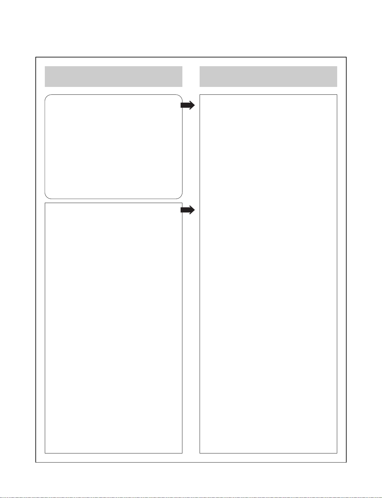
EEPROM option code No. setting procedure
1. DETECT NEW EEPROM (OPTION EDIT
SCREEN)
- Eeprom EDIT screen automatically
appears if replacing Eeprom.
- Setup option data using the cursor
Up/Down key of a remote control.
(Setup upon BOM depending on
OPT0~OPT5 model)
• Since an initial remote control is set to LG
for LG model, appropriately set optiona
data using the cursor Up/Down key.
2. EEPROM WRITED AND EEPROM INITIAL
- Writes data on EEPROM by using
REMOCON "OK" + FRONT PLAY KEY
FOR MORE THAN 5 SECONDS.
3. PG ADJUST
1) Payback the SP standard tape
2) Press the “OK” key on the Remote
controller and the “PLAY” key on the
Front Panel the same time, then it goes
in to Tracking initial mode.
3) Repeat the above step(No.2), then it
finishes the PG adjusting automatically.
4) Stop the playback, then it goes out to
PG adjusting mode after mony the PG
data.
DVP3350V/19 OPT0 90 00000000
OPT1 FC 00000000
OPT2 E8 00000000
OPT3 40 00000000
OPT4 06 00000000
OPT5 4B 00000000
WR : OK I : EXIT MOVE :
EDIT :
1-6

SERVICE INFORMATION FOR EEPROM (DVD)
POWER ON
DVD LOGO Status (NO Disk status)
Remotecontrol
Pause key-->1-->4-->7-->2 in order.
Press number 0~9, Press charater
A~F (1~6 for a while)
Use arrow key ( ) to move
to approprite position and make
changes
DETECT NEW EEPROM (OPTION EDIT SCREEN)
MODEL DVP3350V/01 DVP3350V/02 DVP3350V/05 DVP3350V/19
NAME HEX HEX HEX HEX
OPT1 44 48 47 46
OPT2 45 55 42 52
OPT3 00 00 00 00
OPT4 D3 D3 D3 D3
OPT5 07 07 07 07
OPT6 0F 0F 0F 0F
OPT7 F4 F4 F4 F4
OPT8 00 00 00 00
OPT9 00 00 00 00
OPTA 00 00 00 00
OPTB 80 80 80 80
OPTC 00 00 00 00
OPTD 00 00 00 00
OPTE 00 00 00 00
OPTF 00 00 00 00
OPTG 00 00 00 00
Press pause key once
Change will be applied when power
OFF-->ON.
* OPTION
• NTSC model doesn’t have VCR option and use DVD option B~F as VCR option. (only DVD exist)
• PAL model has another separate VCR option. (Both VCR and DVD exist)
1-7

SPECIFICATIONS
• GENERAL
Power requirements AC 220 ~ 230V, 50Hz
Power consumption 17W
Dimensions (approx.) 430 x 78.5 x 265mm (W x H x D)
Mass (approx.) 4.06kg
Operating temperature 5°C to 35°C (41°F to 95°F)
Operating humidity 5% to 90%
Timer 24 hours display type
RF Modulator UHF 22 ~ 68 (Adjustable)
• SYSTEM
Laser Semiconductor laser, wavelength 650nm
Video Head system Double azimuth 6 heads, helical scanning.
Signal system PAL
Frequency response DVD (PCM 96kHz): 8Hz to 44kHz
DVD (PCM 48kHz): 8Hz to 22kHz
CD: 8Hz to 20kHz
Signal-to-noise ratio More than 100dB (ANALOG OUT connectors only)
Harmonic distortion Less than 0.008%
Dynamic range More than 100dB (DVD)
More than 95dB (CD)
• INPUTS (VCR)
Audio -6.0dBm, more than 10kohms (SCART)
-6.0dBm, more than 47kohms (RCA)
Video 1.0Vp-p, 75ohms, unbalanced (SCART/RCA)
• OUTPUTS (DVD)
VIDEO OUT 1Vp-p 75ohms, sync negative
COMPONENT VIDEO OUT (Y) 1.0V (p-p), 75Ω, negative sync, RCA jack x 1
(Progressive Scan) (Pb)/(Pr) 0.7V (p-p), 75Ω, RCA jack x 2
RGB output 0.7Vp-p, 75ohms
Audio output (coaxial audio) 0.5V (p-p), 75Ω, RCA jack x 1
Audio output (analog audio) 2.0Vrms (1kHz, 0dB), 600Ω,
RCA jack (L, R)x2/SCART (TO TV)
• OUTPUTS (VCR)
Audio -6.0dBm, less than 1kohms (SCART)
Video 1.0Vp-p, 75ohms, unbalanced (SCART)
RGB output 0.7Vp-p, 75ohms
*Design and specifications are subject to change without notice.
1-8

SECTION 2
CABINET & MAIN CHASSIS
CONTENTS
EXPLODED VIEWS.....................................................................................................................................2-2
1. CABINET AND MAIN FRAME SECTION..................................................................................................2-2
2. DECK MECHANISM SECTION [ DVD MD (DP-10C) ].............................................................................2-3
3. DECK MECHANISM SECTION [ VCR DECK D37(N) ]............................................................................2-4
1) FRONT LOADING MECHANISM SECTION.........................................................................................2-4
2) MOVING MECHANISM SECTION (1)...................................................................................................2-5
3) MOVING MECHANISM SECTION (2)...................................................................................................2-6
4. PACKING ACCESSORY SECTION...........................................................................................................2-7
2-1

EXPLODED VIEWS
1. CABINET AND MAIN FRAME SECTION
463
463
THE EXCLAMATION POINT WITHIN AN
NOTES)
EQUILATERAL TRIANGLE IS INTENDED
TO ALERT THE SERVICE PERSONNEL
TO THE PRESENCE OF IMPORTANT
SAFETY INFORMATION IN SERVICE
LITERATURE.
463
250
463
272
300
273
457
470
471
469
A26
A47
271
A00
469
A50
288
324
A46
465
323
CN501
322
469
274
463
330
261
452
285
283
280
286
284
A43
2-2
A44
260
452
261
452

2. DECK MECHANISM SECTION [ DVD MD (DP-10C) ]
A26
012
A02
017
013
015
019
439
435
018
015B
015A
014
440
001
A01
002
003
020
016
012A
432
026
A03
012
2-3
036
030
024
025
439
010
431
435
012A
021
430

3.DECK MECHANISM SECTION [ VCR DECK D37(N) ]
1) FRONT LOADING MECHANISM SECTION
A22
054A
054
100
A21
106
105
107
102
A23
114
032
113
112
109
103
A24
110
116
115
2-4

2) MOVING MECHANISM SECTION (1)
008
026
A03
006
007
015
004
027
014
013
029
009
409
021
031
028
405
406
016
A01
003
022
2-5
012
024
017
011
031
079
032

3) MOVING MECHANISM SECTION (2)
A12
068
069
066
070
023
065
078
076
032
051
052
067
A11
064
061
517
056
077
410
052A
058
080
518
2-6
055
060

4. PACKING ACCESSORY SECTION
808
BATTERY
806
RF CABLE
REMOTE CONTROLLER
900
ASSEMBL
803
PACKING, CASING
802
BOX
Y
INSTRUCTION ASSEMBLY
801
P
ACKING, CASING
803
804
BAG
2-7

MEMO
2-8

SECTION 3
ELECTRICAL
CONTENTS
VCR PART
VCR ELECTRICAL ADJUSTMENT
PROCEDURES
1. SERVO ADJUSTMENT................................3-2
VCR ELECTRICAL
TROUBLESHOOTING GUIDE
1. POWER(SMPS) CIRCUIT ............................3-3
2. SYSTEM/KEY CIRCUIT...............................3-6
3. SERVO CIRCUIT .........................................3-7
4. Y/C CIRCUIT..............................................3-10
5. HI-FI CIRCUIT............................................3-14
6. TUNER/IF CIRCUIT ...................................3-17
BLOCK DIAGRAMS.....................................3-19
1. POWER(SMPS) BLOCK DIAGRAM..........3-19
2. SYSTEM BLOCK DIAGRAM......................3-21
3. A VCP BLOCK DIAGRAM...........................3-23
4. HI-FI BLOCK DIAGRAM ............................3-25
5. TUNER BLOCK DIAGRAM........................3-27
CIRCUIT DIAGRAMS ..................................3-29
1. POWER(SMPS) CIRCUIT DIAGRAM........3-29
2. SYSTEM CIRCUIT DIAGRAM ...................3-31
3. A VCP CIRCUIT DIAGRAM.........................3-33
4. HI-FI CIRCUIT DIAGRAM..........................3-35
5. TUNER CIRCUIT DIAGRAM......................3-37
WAVEFORMS ................................................3-39
CIRCUIT VOLTAGE CHART .........................3-41
IC BLOCK DIAGRAMS..................................3-47
................................................3-2
....................3-3
DVD PART
DVD ELECTRICAL
TROUBLESHOOTING GUIDE
1. POWER CHECK FLOW .............................3-59
2. SYSTEM OPERATION FLOW ...................3-60
3. TEST & DEBUG FLOW .............................3-61
DETAILS AND WAVEFORMS ON
SYSTEM TEST AND DEBUGGING
1. SYSTEM 27MHZ CLOCK,
RESET SIGNAL .........................................3-67
2. SDRAM CLOCK ........................................3-68
3. TRAY OPEN/CLOSE SIGNAL....................3-68
4. SLED CONTROL RELATED SIGNAL
(NO DISC CONDITION) .............................3-70
5. LENS CONTROL RELATED SIGNAL
(NO DISC CONDITION) ............................3-70
6. LASER POWER CONTROL RELATED
SIGNAL (NO DISC CONDITION)...............3-71
7. FOCUS ON WAVEFORM...........................3-71
8. SPINDLE CONTROL WAVEFORM
(NO DISC CONDITION) .............................3-72
9. TRACKING CONTROL RELATED
SIGNAL (SYSTEM CHECKING)................3-73
10. RF WAVEFORM.........................................3-74
11. ZR36966 AUDIO OPTICALAND
COAXIAL OUTPUT (SPDIF).......................3-74
12. ZR36966 VIDEO OUTPUT WAVEFORM...3-75
13. AUDIO OUTPUT FROM
AUDIO PREAMP........................................3-76
..................3-59
........3-67
PRINTED CIRCUIT BOARD
DIAGRAMS
1. MAIN P.C.BOARD (TOP SIDE)..................3-51
2. MAIN P.C.BOARD (BOTTOM SIDE) ..........3-53
3. POWER P.C.BOARD..................................3-55
4. KEY P.C.BOARD........................................3-57
.....................................................3-51
BLOCK DIAGRAMS.....................................3-77
1. SYSTEM BLOCK DIAGRAM......................3-77
2. SERVO BLOCK DIAGRAM ........................3-78
3. AUDIO & VIDEO IN/OUT
BLOCK DIAGRAM .....................................3-79
CIRCUIT DIAGRAMS ..................................3-81
1. MPEG CIRCUIT DIAGRAM........................3-81
2. SERVO CIRCUIT DIAGRAM......................3-83
3. JACK CIRCUIT DIAGRAM.........................3-85
IC BLOCK DIAGRAMS..................................3-87
3-1

VCR PART
VCR ELECTRICAL ADJUSTMENT PROCEDURES
1. SERVO ADJUSTMENT
1) PG Adjustment
• Test Equipment
a) OSCILLOSCOPE C) PAL MODEL : PAL SP TEST TAPE
b) NTSC MODEL : NTSC SP TEST TAPE
• Adjustment And Specification
MODE MEASUREMENT POINT ADJUSTMENT POINT SPECIFICATION
PLAY
H/SW(TP)
R/C TRK JIG KEY 6.5 ±0.5H
• Adjustment Procedure
V.Out
a) Insert the SP Test Tape and play.
Note - Adjust the distance of X, pressing the Tracking(+) or Tracking(-) when the “ATR” is blink after the
SP Test Tape is inserted.
b) Connect the CH1 of the oscilloscope to the H/SW(TP) and CH2 to the Video Out for the VCR.
c) Trigger the mixed Combo Video Signal of CH2 to the CH1 H/SW(TP) and then check the distance (time
difference), which is from the selected A(B) Head point of the H/SW(TP) signal to the starting point of
the vertical synchronized signal, to 6.5H ± 0.5H (412µs, 1H=63µs).
• PG Adjustment Method
a-1) Playback the SP standard tape
b-2) Press the “OK” key on the Remote control and the “REC” key on the Front Panel at the same time for
more than 5seconds, then it goes in to Tracking initial mode.
c-3) Repeat the above step(No.b-2), then it finishes the PG adjusting automatically.
d-4) Stop the playback, then it goes out to PG adjusting mode after mony the PG data.
• CONNECTION
V.Out
OSCILLOSCOPE
•WAVEFORM
H/SW(TP)
H/SW
Composite
VIDEO
6.5H(416us)
3-2
R/C KEY
CH1 CH2
H/SW
(TP)
V.out
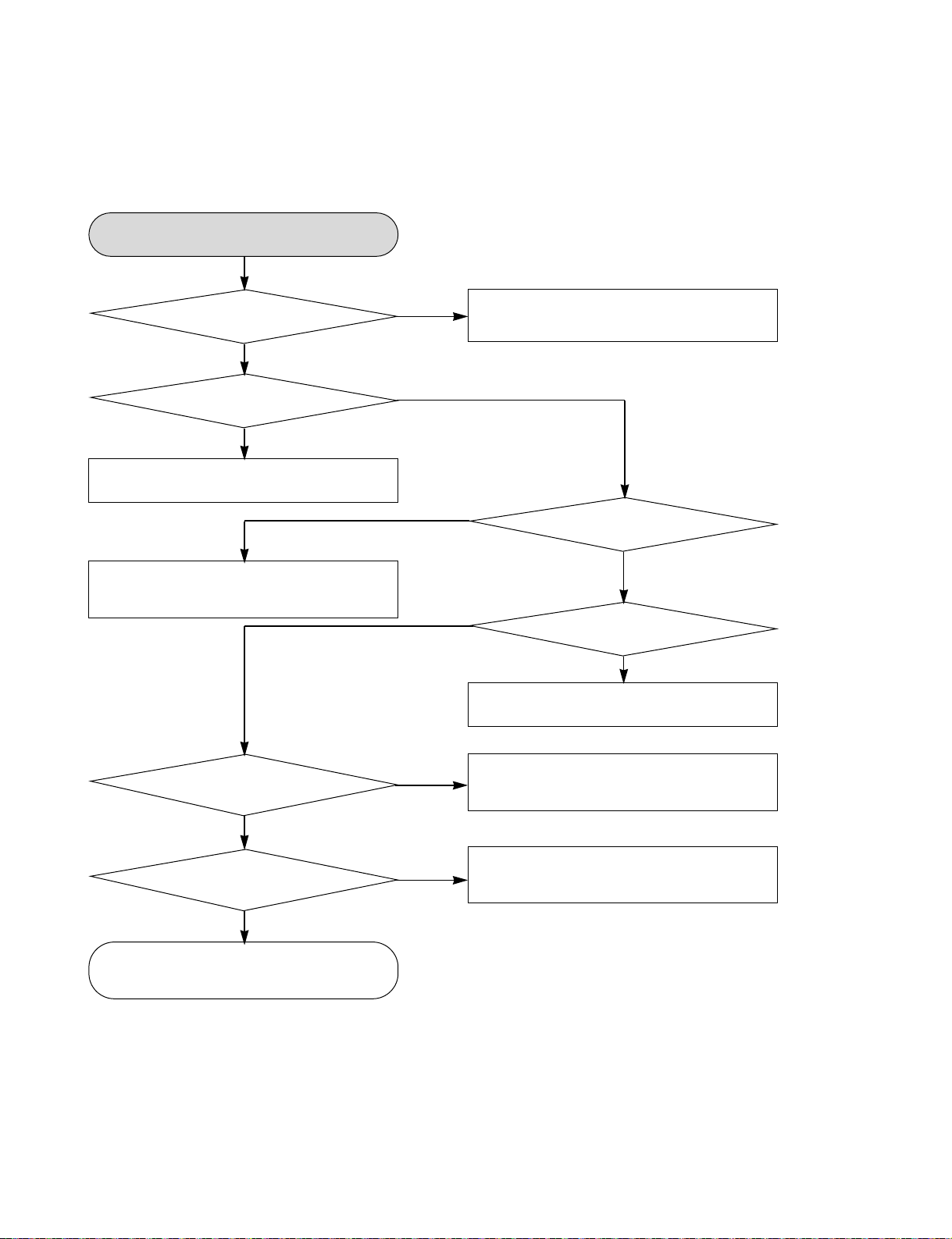
VCR ELECTRICAL TROUBLESHOOTING GUIDE
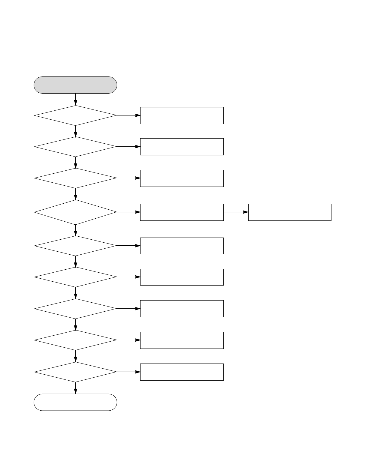
1. POWER(SMPS) CIRCUIT
1-1. No 5.3VA
No 5.3VA
YES
Is the FR101
Normal?
YES
Is the BD101
Normal?
YES
Is the R101
Normal?
YES
Is Vcc
(9V ~ 18V) supplied
to IC101 Pin2?
YES
Are the D125
normal?
YES
Is there
about 2.5V at the
IC103 Pin1?
YES
NO
NO
NO
NO
NO
NO
Replace FR101
(Use the same ICW)
Replace the BD101
Replace the R101
Is the D102 normal?
Replace the D125
Replace the IC103
NO
Check or Replace the D102
Is the D123
normal?
YES
Is the D124
Normal?
YES
Is the D121
Normal?
YES
Power Line of Main
PCB is short
NO
NO
NO
Replace the D123
Replace the D124
Replace the D121
3-3

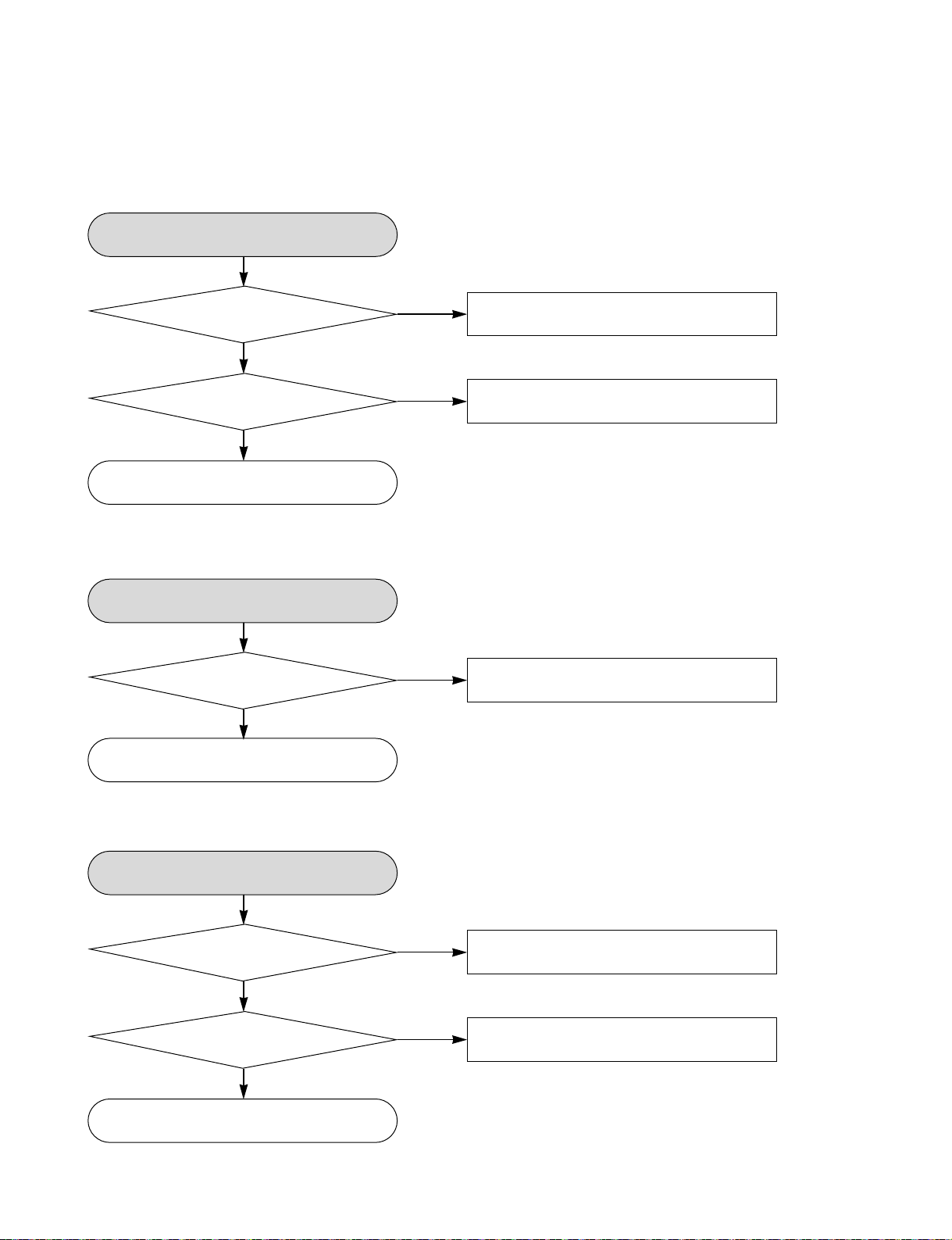
VCR ELECTRICAL TROUBLESHOOTING GUIDE
1-2. No 5.0V_D
No 5.0V_TNo 9V
YES
Vcc(5.3V) supplied to
Q165 Emittor?
Q162 Base “H”?
Check or Replace
1-3. No 5.0V_T
Vcc(5.3V) supplied to
Q163 Emittor?
Is the
YES
Is the
YES
the Q165
No 5.0V_T
YES
Is the
YES
NO
NO
NO
Check or Replace the D125
Check the PWR CTL
“H” signal from µ-com
Check or Replace the D125
Check or Replace the Q163
1-4. No 3.8V
Is the
Q162 Base “H”?
YES
No 3.8V
YES
Is the D123
normal?
YES
Power line of Main
PCB is short
NO
NO
Check the PWR CTL
“H” signal from µ-com
Check or Replace the D123
3-4
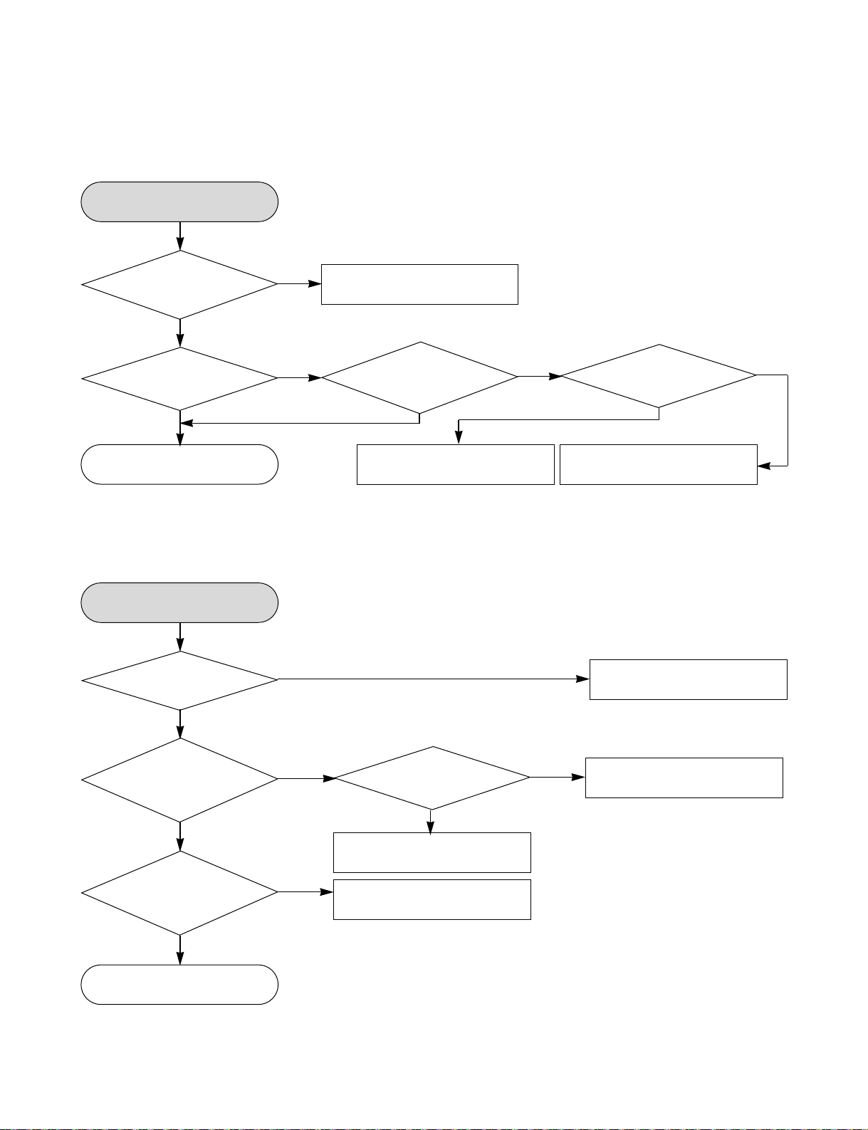
VCR ELECTRICAL TROUBLESHOOTING GUIDE
1-5. No 33V
No 33V
YES
Vcc(33V) supplied to
Is the
Q161 Emittor?
YES
Is the Q162 Base
“H”?
YES
Check or Replace the Q161
1-6. No Motor_Vcc (To Cap, Drum Motor)
No Motor_Vcc
YES
Is the Vcc(14V)
supplied to C134?
YES
NO
NO
NO
Check or Replace the D121
Check the PWR CTL
“H” signal from µ-com
Check or Replace the D124
Check or Replace the Cap / Drum
1-7. No REG 12V
No REG 12V
YES
Is the
Vcc(14V) supplied to
Q165 Collector?
YES
Is the
Vcc(14V) supplied to
Q165 Base?
YES
Check or Replace the Q165
NO
NO
Check or Replace D124
Check the PWR CTL
“H” signal from µ-com
3-5
VCR ELECTRICAL TROUBLESHOOTING GUIDE
2. SYSTEM/KEY CIRCUIT
2-1. AUTO STOP
Auto Stop
YES
Does the
SW25 waveform
appear at the IC501
NO
Check the Drum Motor
signal.
Pin23?
YES
Do the
T-UP Reel Pulses
appear at the IC501
Pin3?
YES
Replace the IC501.
NO
YES
Do T/UP
Reel Pulses appear
at the Q514 Base
terminal?
Replace the T/UP Reel
2-2. The unstable loading of a Cassette tape
The unstable loading
of a Cassette tape
YES
applied to the PMC01
Is 12V
Pin8?
NO
Sensor (RS501).
NO
Does 5.0V
appear at the
RS501?
YES
Check the Power Circuit.
Check the Power.
NO
YES
Does the
“H” signal appear
at the IC501 Pin32
during inserting
NO
Is 5.0V
applied to the
R544 ?
the CST?
YES
YES
Check the CST SW and
Does the
“L” signal appear
at the IC501 Pin19
during inserting
NO
the peripheral circuitry.
Check the IC501
Pins 86, 87, 88, 89.
the CST?
YES
Check the Deck
Mechanism.
Caution : Auto stop can occur because Grease or Oil is dried up
3-6
NO
Refer to SMPS 5.3VA
troubleshooting.

VCR ELECTRICAL TROUBLESHOOTING GUIDE
3. SERVO CIRCUIT
3-1. Unstable Video in PB MODE
Unstable Video in
PB Mode.
YES
Does the Noise level of the
screen change periodically?
YES
Does the CFG waveform
appear at the IC501 Pin67?
YES
On tracking
do the CTL pulses
move?
YES
Does the
Video Envelope waveform
appear at the IC501
Pin82?
YES
Replace the IC501.
3-2. When the Drum Motor
doesn’t run.
When the Drum Motor
doesn’t run,
YES
Does 12V
appear at PMC01
Pin8?
YES
Does 2.8V
appear at PMC01
Pin12?
YES
Check the connector
(PMC01) and the Drum
Motor Ass’y .
NO
NO
NO
NO
Replace the IC501.
Refer to “When the Y
signal doesn’t appear on
the screen in PB Mode”.
Refer to “(2)
No 12VA of Power section”
Do the
Drum PWM Pulses
appear at the IC501
Pin34?
YES
Aren’t the foil patterns and
the Components between
IC501 Pin34 and PMC01
Pin12 short?
Do the DFG
Pulses appear at the
IC501 Pin104?
YES
Do the
Drum PWM Pulses
appear at IC501
Pin34?
YES
NO
NO
NO
YES
Do the
DFG Pulses appear
at the PMC01
Pin11?
Replace the Cap M.
Aren’t the foil patterns and
the Components between
IC501 Pin 104 and PMC01
Pin11 short?
Replace the IC501.
NO
Aren’t the connecting patterns and the Components
between IC501 Pin34 and PMC01 Pin12 short?
3-7
VCR ELECTRICAL TROUBLESHOOTING GUIDE
3-3. When the Capstan Motor doesn’t run,
When the Capstan Motor doesn’t run,
Does
12VA appear at the
PMC01?
YES
Does
2.8V appear at the
PMC01?
YES
Check the PMC01 and the
Capstan Motor Ass’y.
YES
Aren’t the foil patterns and Components
between IC501 Pin33 and PMC01
Pin9 short?
YES
NO
Refer to “SMPS(CAPSTAN/12Volt)
Trouble Shooting”.
NO
Does the
PWM signal appear at the
IC501 Pin33?
NO
Does the
CFG signal appear at the
PMC01 Pin1?
NO
Check the Capstan Motor Ass’y.
Does the
CFG signal come into the
IC501 Pin67?
YES
Does the
Capstan PWM signal appear at
the IC501 Pin33?
YES
Aren’t the foil patterns and Components
between IC501 Pin33 and PMC01
Pin9 short?
NO
NO
Aren’t the foil patterns and component
between IC501 Pin67 and PMC01
Pin1 short?
Replace IC501.
3-8
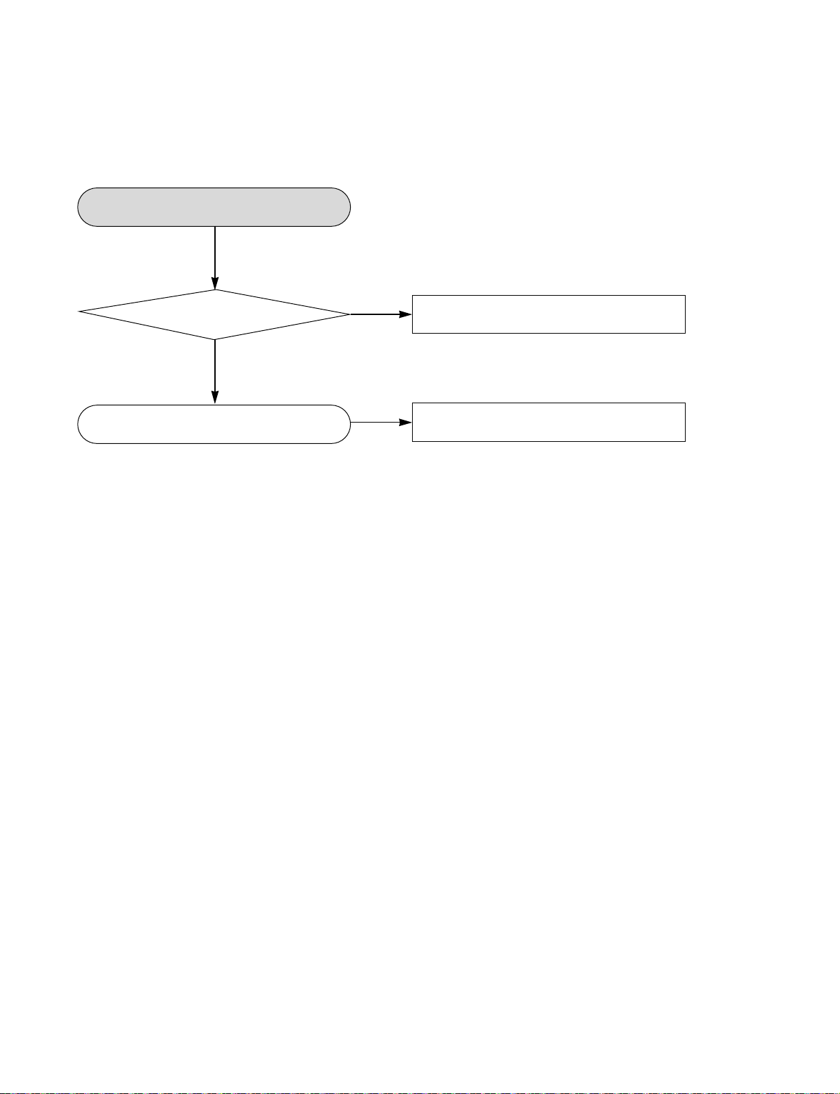
VCR ELECTRICAL TROUBLESHOOTING GUIDE
3-4. KEY doesn’t working
KEY doesn’t working.
YES
Is 5V
applied to the IC501
Pin36?
YES
Does LED or FLD change
when a function button is pressed?
NO
NO
Refer to “SMPS 5.3VA Trouble Shooting”.
Replace the defective switches.
3-9
VCR ELECTRICAL TROUBLESHOOTING GUIDE
4. Y/C CIRCUIT
4-1. No Video in EE Mode,
No Video in EE Mode
YES
Does the
Video signal appear
at the IC301
Pin48?
YES
Is 5V
applied to the IC301
Pins18, 24, 42, 55,
72, 91?
YES
Does the Video
signal appear at the
IC301 Pin65?
YES
NO
NO
NO
Check the 19Pin of Tuner.
Check the 5.0VT, 5.3VA
Line. (Power Circuit)
Is I2C BUS
signal applied to the
IC301 Pins68,
69?
YES
Check C316. (AGC)
YES
Replace the IC301.
NO
Check the System Circuit.
(Refer to “SYSTEM I2C BUS
Check Trouble Shooting”)
Does the Video
signal appear at the
IC501 Pin47?
YES
Does the Video signal
appear at the Emitter
terminal of the Q309?
NO
NO
Chck the path of the signal
between the IC301 Pin65
and IC501 Pin49.
Does the
12VT, 5.3VA appear
at the Emitter terminal
of the Q309.
YES
Replace the Q309.
3-10
NO
Check the 12VT, 5.4VA
Line. (Power Circuit)

VCR ELECTRICAL TROUBLESHOOTING GUIDE
4-2. When the Y(Luminance) signal doesn’t appear on the screen in PB Mode,
When the Y(Luminance)
signal doesn’t appear on
the screen in PB Mode,
YES
Is 5.0VT,
5.3VA applied to the
IC301 Pins24, 42, 55,
72, 91?
YES
Is the I2C
Bus siganl applied
IC301 to the Pins68,
69?
YES
Does the
normal RF signal
appear at the IC301
Pin78?
YES
NO
NO
NO
Check the line of the 5.0VT,
5.3VA Line. (Power Circuit)
Refer to “SYSTEM I2C BUS
Check Trouble Shooting”.
Is the
V.H.S/W signal
applied to the IC301
Pin70?
YES
Is V.H.S/W “H”
about 3.4V at the
IC301 Pin70?
YES
Clean the Drum.
NO
NO
NO
Check the System Circuit.
(IC501 Pin23)
Check the V.H.S/W level.
(Check R303, R304)
Replace the IC301.
Does the
Y(Luminance) RF
signal appear at the
IC301 Pin79?
YES
Is the
Y(Luminance) Video
waveform showed up
at the IC301
Pin43?
YES
Replace the IC301.
NO
NO
Check the path of the
Y(Luminance) RF signal.
(Check the C312)
Check the path of the
Y(Luminance) RF signal.
(Check C327)
3-11
YES
YES

VCR ELECTRICAL TROUBLESHOOTING GUIDE
4-3. When the C(Color) signal doesn’t appear on the screen in PB Mode,
When the C(Color) signal
doesn’t appear on the
screen in PB Mode,
YES
Is 5.0VT/
5.3VA applied to the
IC301 Pins24, 42,
55, 72, 91.
YES
Is the Color
Rotary signal
applied to the IC301
Pin70?
YES
Is Color Rotary “H”
about 3.4V?
YES
Does the
Color signal
appear at the IC301
Pin25 ?
YES
NO
NO
NO
NO
Check the line of the 5.0VT/
5.3VA Line. (Power Circuit)
Check the Color Rotary
Circuit. (IC501 Pin98 )
Check the Color Rotary
level. (Check the R303)
Does the
X301(4.43MHZ)
oscillate?
YES
Does the
Color signal
appear at the IC301
Pin21?
NO
NO
Replace the X301.
Check the Color Pass.
Replace the IC301.
YES
Replace the IC301.
3-12

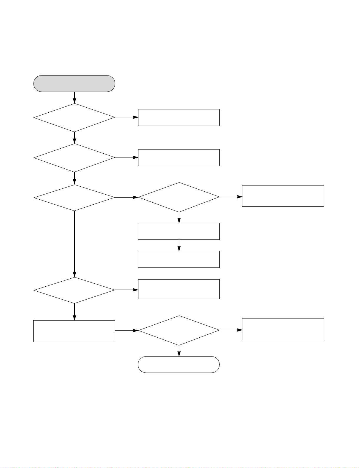
VCR ELECTRICAL TROUBLESHOOTING GUIDE
4-4. When the Video signal doesn’t appear on the screen in REC Mode,
When the Video
signal doesn’t appear on
the screen in REC Mode,
YES
Is the EE
signal normal?
YES
Is 5.0VT/
5.3VA applied to the
IC301 Pins24,42,55,
72,91?
YES
Does PB
Mdoe operate
normally?
YES
Does the RF
signal appear at the
IC301 Pin78?
YES
NO
NO
NO
NO
Check EE Mode.
Check the line of the 5.0VT/
5.3VA Line.(Power Circuit)
Check PB Mode.
Is the REC
“H” signal (about 4V)
applied to the IC301
Pin80?
YES
Check REC Luminance
Pass & Color Pass.
NO
YES
Check the System
of REC “H”.
(the IC501 Pin27 / the D301)
Replace the IC301.
Does the
REC RF signal appear
at the IC301 Pins88,
89,94,95?
YES
Check the Drum &
Drum Connector
NO YES
Check the circuit of the
IC301 Pins85, 86.
3-13
 Loading...