

Philips DVP3326/94 Service Manual
DVD Player DVP3326/94
Published by BU AVM – FK Printed in the Netherlands Subject to modification
Version 1.0
TABLE OF CONTENTS
Chapter
Technical Specification & Service Tips…………..……….. 1
Safety Instructions…………………………………………….. 2
Instruction for Use……………………………………………… 3
Mechanical Instructions………………………………………. 4
Troubleshooting …………………………………………………5
Overall Block Diagram…………………………………………. 6
Electrical Diagram……………………………………………… 7
Exploded View Diagram & Service Part List………………..8
Revision List……………………………………………………. 9
©Copyright 2005 Philips Consumer Electronics B.V. Eindhoven, The Netherlands
All rights reserved. No part of this publication may by reproduced, stored in a
retrieval system or transmitted, in any form or by any means, electronics,
mechanical, photocopying, or otherwise without the prior permission of Philips
Service Manual
3141 785 34250

1.0 TECHNICAL SPECIFICATION
V
IDEO PERFORMANCE
Test equipment:Tektronics VM700T
Test discs:DVD test disc:Philips LVP 10。01
(PAL)/Abex TDV-540(NTSC)
Load Impedance:75Ω
V
IDEO FORMAT
DVD,VCD,MP3,JPEG
USB:2.0 HS,support MSC,MTP,sector size 4K
AUDIO PERFORMANCE
Line outputs
Test equipment:Audio Precision System2
Test discs:CDDA:Philips audio signal test disc 1
Load Impedance:100KΩ for Audio
AUDIO FORMAT
CD/MP3,DVD audio
CVBS
Amplitude output:1Vpp± 0.1V/
White bar:
714mV ± 10%/700mVpp ± 10%
Sync. Amplitude: 286mV ±100mV/300mVpp ± 100mV
Burst/chroma ratio: ± 10%
S/N luminance: ≥52 dB
COMPONENT VIDEO RGB
Luminance amplitude output: 700mV ± 10%
RGB unbalance:5%
Sync. Amplitude: 300mV ± 100mV
S/N on RGB outputs: ≥52 dB
DC Level:
≤
1V
COMPONENT VIDEO YPbPr
PbPr output unbalance:3%
Sync. Amplitude: 286mV ± 100mV
Video Bandwidth 4.2 MHz:-5db
S/N on outputs: YUV: ≥52 dB
POWER CONSUMPTION
Power-Supply:100-280V ac,50/60Hz,standby:310V
Supply voltage:AC 100~280V
Supply Power consumption(AC 100/240V):12W/+10%
Standby Power,230VAC: <1W
GENERAL DESCRIPTION
Optical Pickup:IM S76RFVP
Chip set/Solution:Mediatek MTK1389QE-LA
Disc Size:8cm/12cm
1.1 PCBs LOCATION
VERSION VARIATIONS
Type/Versions:
Service policy
Board in used:
DVP3336
94
MAIN BOARD
8W/2P POWER BOARD
LED DISPLAY BOARD
USB BOARD
POWER SW BOARD
*TIPS: C -- Component Lever Repair.
M -- Module Lever Repair
X – Used
DVD BOARD
LED DISPLAY BOARD
DECK AMI
POWER SW BOARD
USB BOARD
8W/2P POWER BOARD
M/C
M
M/C
M/C
M
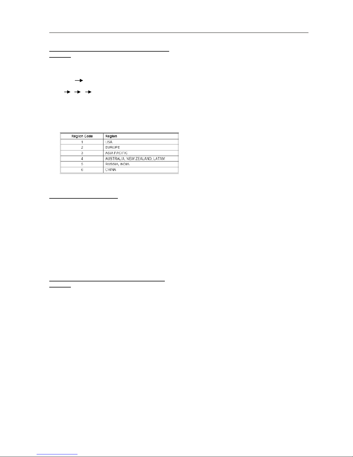
1.2 System, Region Code, etc. Setting Procedure
Procedure to change region code of your DVD
Portable
1. Power ON the DVD player and do not insert
DISC inside player
2. Setup Prefer
Press IR in the sequence as
9 6 5 3
The LCD display showed the existing region
Code
3. Press▲(navigation up)or▼(navigation down)
repeatedly to select the number from 0 to 6.
4. Then press OK to confirm your region code.
5. Refer below table for your region code setting
Select “0” setting = Region Free (confidential)
Procedure for SW upgrade
1. The upgrade will provide a document
re-named: PHILIPS.BIN
2. “PHILIPS.BIN” copy to USB or CD-ROM into
the data;
3. Reading the USB or CD-ROM,in accordance
with prompt,press ”OK” key to upgrade.
Warning: Do not unplug the AC adapter during
firmware upgrade to prevent flash corrupt of
the set!!
Procedure to check SW version of your DVD
Portable
1. OPEN
2. Press SETUP MENU
3. Select Preferences
4. Select Version Info
5. Press “OK” key

2.0 Safety instruction
1. General safety
Safety regulations require that during a repair:
. Connect the unit to the mains via an isolation
transformer.
. Replace safety components indicated by the
symbol
Only by components identical to the original ones.
Any
Other component substitution (other than original
type)
May increase risk of fire or electrical shock hazard.
Safety regulations require that after a repair, you
must
Return the unit in its original condition. Pay, in
particular,
Attention to the following points:
. Route the wires/cables correctly, and fix them with
the
mounted cable clamps
. Check the insulation of the mains lead for external
Damage
. Check the electrical DC resistance between the
mains
Plug and the secondary side:
1) Unplug the mains cord, and connect a wire
between
The two pins of the mains plug.
2) Set the mains switch the “on” position (keep
the
Mains cord unplug).
3) Measure the resistance value between the
mains
plug and the front panel, controls, and chassis
bottom.
4) Repair or correct unit when the resistance
measurement is less than 1M Ω
5) Verify this, before you return the unit to the
customer/user (ref. UL-standard no. 1492).
6) Switch the unit “off”, and remove the wire
between
the two pins of the mains plug.
2. Laser safety
This unit employs a laser. Only qualified service
personnel
May remove the cover, or attempt to service this
device
(due to possible eye injury).
Laser device unit
Type :Semiconductor laser GaAIAs
Wavelength :650nm (DVD)
:780nm (VCD/CD)
Output power :7mW(DVD)
:10mW(DVD/CD)
Beam divergence:60 degree
Note: Use of controls or adjustments or
performance of procedure other than those
specified herein, may result in hazardous
radiation exposure. Avoid direct exposure to
beam.

3.0 INSTRUCTION FOR USE
You can download this information from the following websites:
http://www.philips.com/support
http://www.p4c.philips.com
4.0 MECHANICAL AND DISMANTLING INSTRUCTIONS
The following guidelines show how to dismantle the player.
Step1: Remove 5 screws around the Top Cover, and then remove the Top Cover(Figure1)
Figure 1
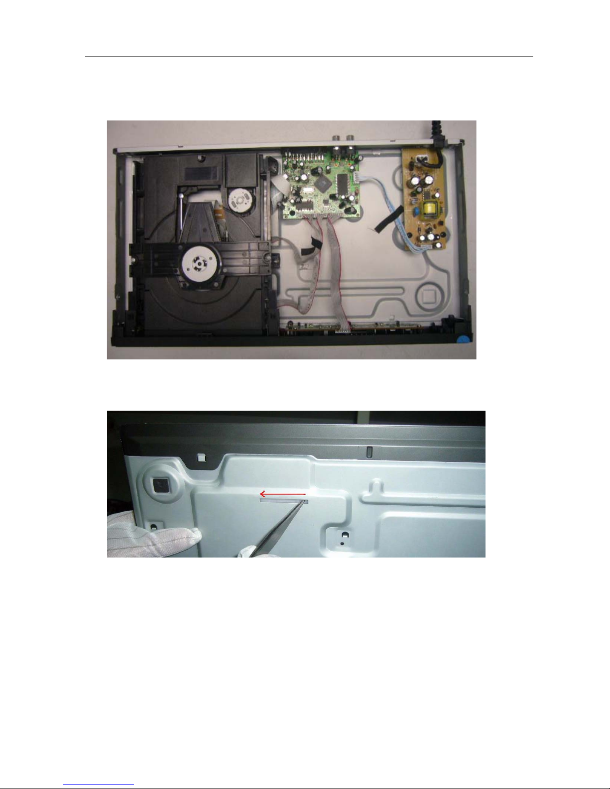
Step2:If the tray can’t open in normal way, you can make it through the instruction as below (Figure2)
Figure 2
Step2: If it is necessary to dismantle Loader or Front Panel, the Front door should be removed first(Figure3)
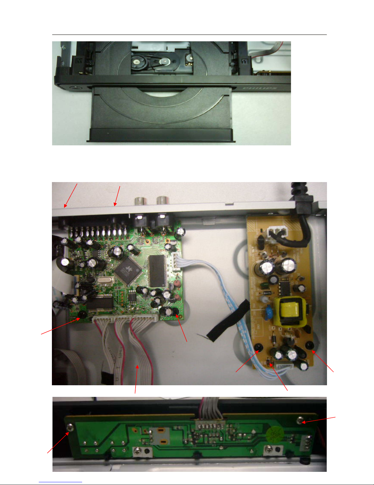
Figure3
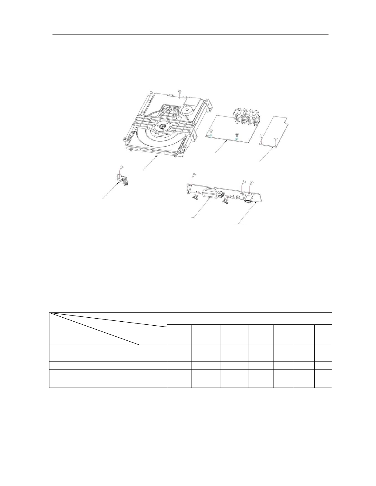
Step4: Remove the 10 screws on board to dismantle the DVD BOARD & POWER BOARD & LED BOARD (Figure 4&5)
Figure4
4.0 MECHANICAL AND DISMANTLING INSTRUCTIONS
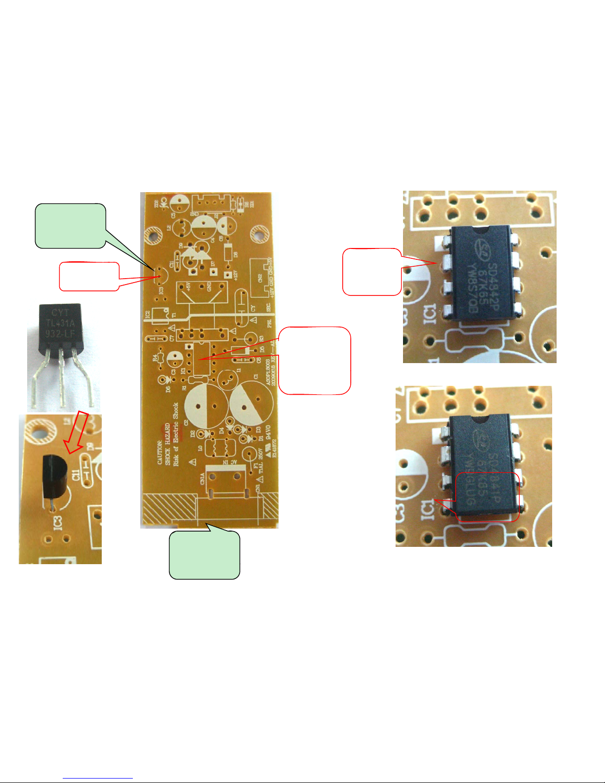
插IC1位置:
DVP3336用
SD4842P.
插IC3位置:
CYT431
插IC1位置:
DVP3336用
SD4842P.
DVP3336和
DVP3320/3326共
用此IC
DVP
3320/3326
用
SD4841P.
DVP3336和
DVP3320/3326共
插IC1位置:
DVP3320/3326
用SD4841P.
用此
PCB
板
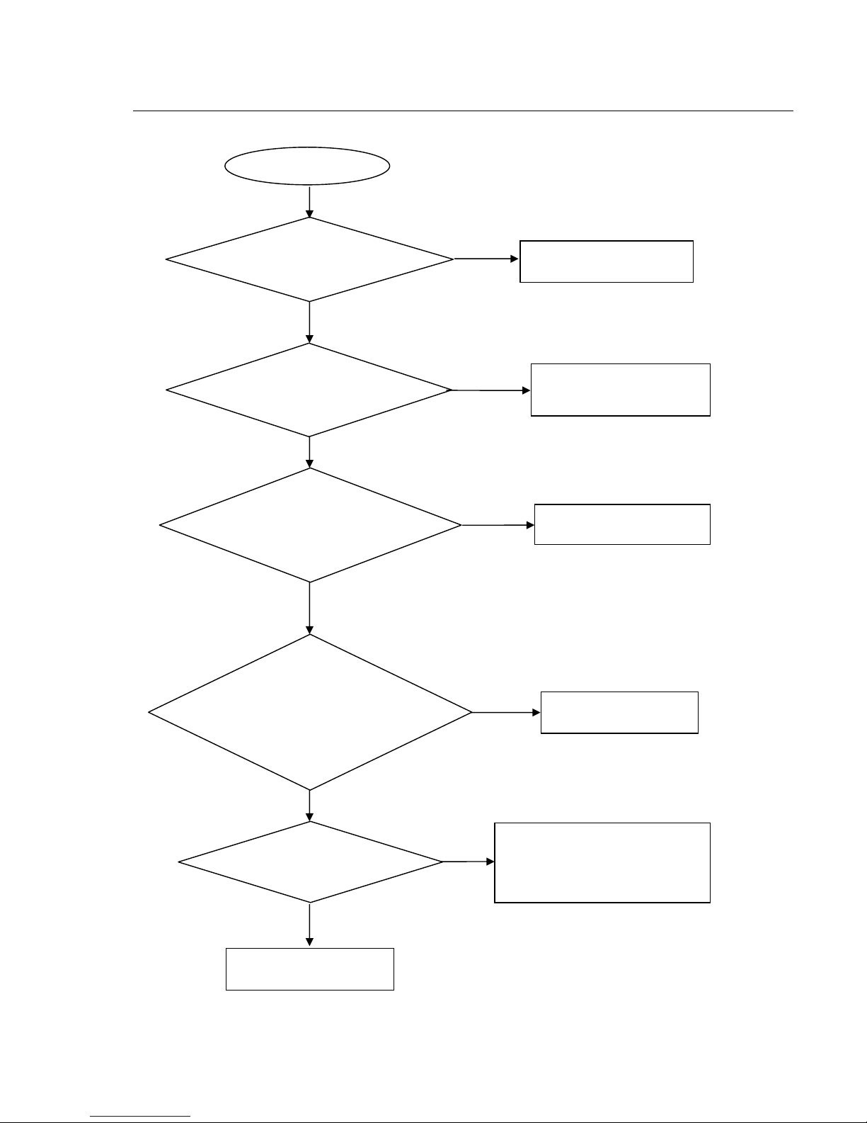
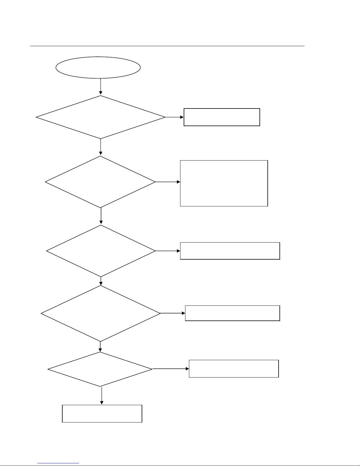
Spindle motor does not move
Yes
Yes
No
No
No
No
Yes
Check whether “MO_VCC”
(VCC) voltage is normal.
Correct connection
Check the MOVCC power
supply
Check/Replace Q13ǃQ10.
Check/ Replace U2.
Check opu focus
1. Check U2 25pin FOO signals
2.If there are F+, F-, T+ and T-
signals output from U1.
Check/Replace the loader
Yes
Yes
No
Go
Check whether laser voltage
(1.9V for CD & 2.3V for DVD)
on L23 & L22
Check the FFC connection
between 24P and the loader.
1. Whether voltage on pin 23 of U2
varies between 0 and 3.3V (3.3V
for CD and 0V for DVD),
2. Whether peripheral components
are eroded or badly soldered.
Trouble shooting chart
Motor not move
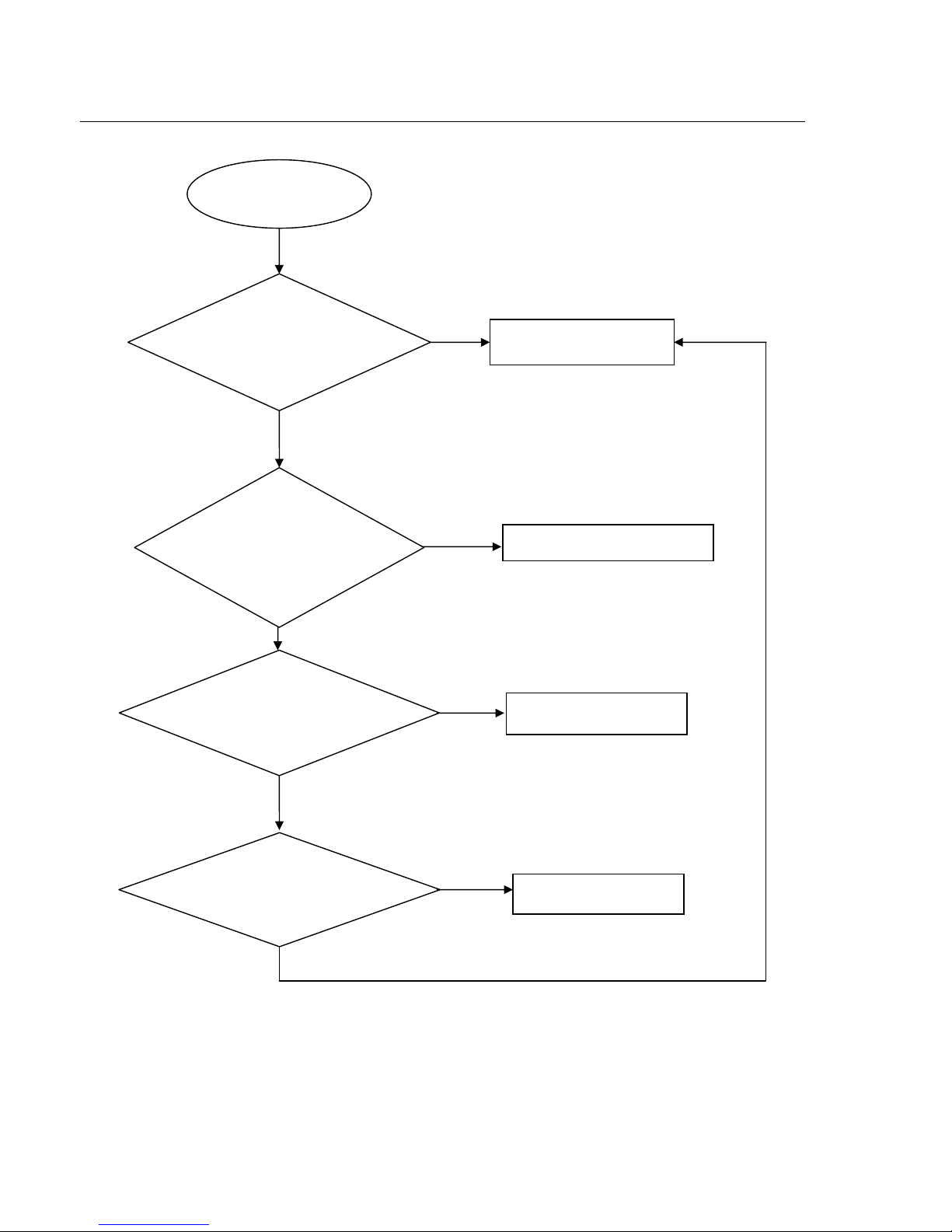
The power can not be on or off
Go
Ye s
Yes
No
No
The power can’t be
on or off
Yes
Replace the power board
Check the power supply
on the power board and the connection to
to decoder board is normal.
Check/Correct connection
Whether the connection
to Standby Board is broken.
Correct the connection
Replace U2.
No
No
Yes
Yes
Check if the J 2 on the front
board to J 4(7PIN) on the decoder board
is in good contact.
Whether there is 0V or
3.3V voltage difference on
Pin41 of U2
Trouble shooting chart
or correct the connection
Disc cannot be read
.
No
Yes
No
Yes
No
Yes
Yes
No
No
Yes
Disc cannot be read.
Check the loaded circuit
1.Check voltage on pin 23 of U2
varies between 0 and 3.3V:
Æ3.3V for CD
Æ0V for DVD
2.Check whether peripheral
components are eroded or defect
Check the FFC connection
between 24P and the loader.
Check U2 and peripheral components
Re-solder or replace the defective parts
Check the connection
between U2
Correct connection
Replace U2 or loader.
Yes
Check whether there is
laser voltage (1.9V for CD
and 2.3V for DVD) on
Collector of Q13 &Q10
Check if there is RFO signal
on the pin8 of HA1. (The
normal RFO signal is a clear
reticulated wave)
Check U1, U2, and
peripheral components are
eroded or badly soldered.
Trouble shooting chart
 Loading...