

Philips DVP-3236 Service Manual
DVD Player DVP3236/94 & DVP3236X/94
Service
Service Manual
Contents Survey of versions:
Chapter /94
Sec. 1: Adjustment Procedures
Schematic Diagrams and CBA's
Exploded Views
Spare Parts Lists
c Copyright 2005 Philips Consumer Electronics B.V. Eindhoven, The Netherlands.
All rights reserved. No part of this publication may be reproduced, stored in a retrieval
system or transmitted, in any form or by any means, electronic, mechanical, photocopying,
or otherwise without the prior permission of Philips.
Published by LM0820 Service AV Systems Printed in The Netherlands Subject to modification EN 3139 785 34141
Version 1.1

MAIN SECTION
DVD PLAYER
Main Section:
Adjustment Procedures
Schematic Diagrams and CBA’s
Exploded Views
Spare Parts List
TABLE OF CONTENT
LASER BEAM SAFETY PRECAUTIONS . . . . . . . . . . . . . . . . . . …. . . . . . . . . . . . . . . . . . . .. . . 1
IMPORTANT SAFETY PRECAUTIONS. . . . . . . . . . . . . . . . . . . . . . . . . ….. . . . . . . . . . . . .. . . . 2
STANDARD NOTES FOR SERVICING . . . . . . . . . . . . . . . . . . . . . . . . . . . …. . .. . . . . . .. . . . . . 3
OPERATING CONTROLS AND FUNCTIONS. . . . . . . . . . . . . . . . . . . . . . . . . ... . . . . . .. . .. . . . 7
DISASSEMBLY INSTRUCTIONS . . . . . . . . . . . . . . . . …………… . . . . . . . . . . . . . . . . .. . .. . . . 9
HOW TO INITIALIZE THE DVD PLAYER . . . . . . . . . . . . . . . . . . . . . . . . . . . . . . . . . .. .. .. . . . . 17
MODE FOR SERVICE…………………………………………………………………………….. …19
FIRMWARE RENEWAL MODE . . . . . . . . . . . . . . . . . . . . . . . . . . . . . . . . . . . . . . . . . . . . . . . . . 21
BLOCK WIRING DIAGRAMS. . . . . . . . . . . . . . . . . . . . . . . . . . . . . . . . . . . . . . .. . . . . . . . . . . . . 22
SCHEMATIC DIAGRAMS ………………………………… . . . . . . . . . . . . . . . . . . . . . . . . . …. ... 23
WAVEFORMS . . . . . . . . . . . . . . . . . . . . . . . . . . . . . . . . . . . . . . .. . . . . . . . . . . . . . . . . . . . . . . . 41
SYSTEM CONTROL TIMING CHARTS. . . . . . . . . . . . . . . . . . . . . . . . . . . . . . . . . . . . .. . . . . . 46
EXPLODED VIEWS. . . . . . . . . . . . . . . . . . . . . . . . . . . . . . . . . . . . . . . . . . . . . . . . . . . . . . . . . . . 47
SPARE PARTS LIST . . . . . . . . . . . . . . . . . . . . . . . . . . . . . . . . …… . . . . . . . . . . . . . …… . . . .. 48
REVISION LIST……………………………………………………………………..…………………….51
LASER BEAM SAFETY PRECAUTIONS
Page 1 of 51
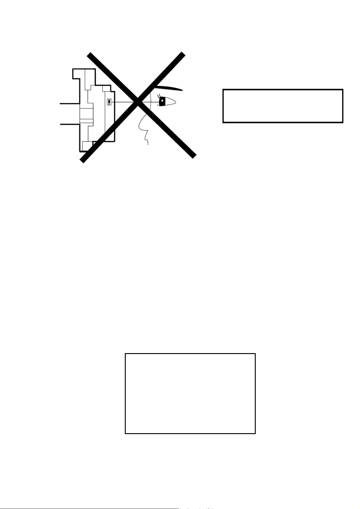
This DVD player uses a pickup that emits a laser beam.
Do not look directly at the laser beam
coming from the pickup or allow it to
strike against your skin.
The laser beam is emitted from the location shown in the figure. When checking the laser
diode, be sure to keep your eyes at least 30 cm away from the pickup lens when the diode is
turned on. Do not look directly at the laser beam.
CAUTION: Use of controls and adjustments, or doing procedures ot her than those specified
herein, may result in hazardous radiation exposure.
CAUTION
LASER RADIATION
WHEN OPEN. DO NOT
STARE INTO BEAM.
Location: Top of DVD mechanism.

IMPORTANT SAFETY PRECAUTIONS
Page 2 of 51
Product Safety Notice
Some electrical and mechanical parts have
special safety-related characteristi cs wh ich
are often not evident from visual inspection,
nor can the protection they give necessarily be
obtained by replacing them with components
rated for higher voltage, wattage, etc. Parts
that have special safety characteristics are
identified by a # o
lists. Use of a substitute replacement that
does not have the same safety characteristics
as the recommended replacement part might
create shock, fire, and/or other hazards. The
Product’s Safety is under review continuously
and new instructions are issued whenever
appropriate. Prior to shipment from the factory,
our products are carefully inspected to confirm
with the recognized product safety and
rical codes of the countries in which they
elect
are to be sold. However, in order to maintain
such compliance, it is equally important to
implement the following precautions when a
set is being serviced.
Precautions during Servicing
A. Parts identified by the # symbol are critical
for safety. Replace only with part number
specified.
B. In addition
assemblies are specified for conformance with
regulations applying to spurious radiation.
These must also be replaced only with
specified replacements. Examples: RF
converters, RF cables, noise blocking
capacitors, and noise blocking filters, etc.
C. Use sp
especially:
1) Wires covered with PVC tubing
2) Double insulated wires
3) High voltage leads
D. Use sp
hazardous live parts. Note especially:
1) PVC tubing
2) Spacers
3) Insulators for transistors
E. When replacing AC primary side
com
wrap ends of wires securely about the
terminals before soldering.
F. Obse
ecified internal wiring. Note
ecified insulating materials for
ponents (transformers, power cord, etc.),
rve that the wires do not contact heat
n schematics and in parts
to safety, other parts and
producing parts (heat sinks, oxide metal film
resistors, fusible resistors, etc.).
G. Che
sharp edges or pointed parts.
H. Whe
check that5 - 6 kg of force in any direction will
not loosen it.
I. A
locations.
J. B
solder droplets, etc.) do not remain inside the
set.
K. Crim
The power transformer uses crimp type
con
the primary side of the transformer. When
replacing the transformer, follow these steps
carefully and precisely to prevent shock
hazards.
Replacement procedure
1) Remove the old connector by cutting the
wires at a poi
Important: Do not re-use a con
(Discard it.)
2) Strip about 15 mm of the insulation from the
ends of the wires. If the wires a
twist the strands to avoid frayed conductors.
3) Align the lengths of the wires to be
c
connector.
4) Use a crimping tool to crimp the metal
sleeve at its center. Be su
the complete closure of the tool.
L. When
internal connectors, first, disconnect the AC
plug from the AC outlet.
ck that replaced wires do not contact
n a power cord has been replaced,
lso check areas surrounding repaired
e careful that foreign objects (screws,
p type wire connector
nectors which connect the power cord and
nt close to the connector.
nector.
re stranded,
onnected. Insert the wires fully into the
re to crimp fully to
connecting or disconnecting the
STANDARD NOTES FOR SERVICING
Page 3 of 51
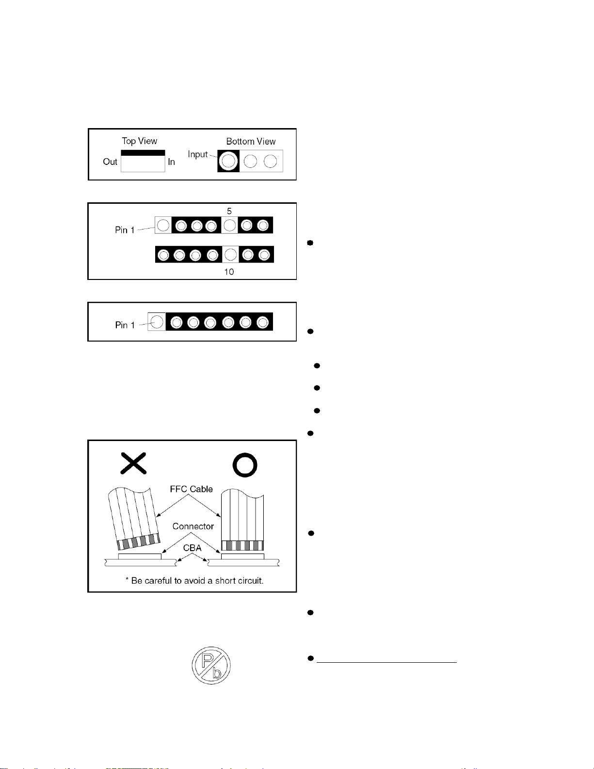
Circuit Board Indications
1. The output pin of the 3 pin Regulator ICs is
indicated as shown.
2. For other ICs, pin 1 and every fifth pin are
indicated as shown.
3. The 1st pin of every male connector is
indicated as shown.
Instructions for Connectors
1. When you connect or disconnect the FFC
(Flexible Foil Connector) cable, be sure to first
disconnect the AC cord.
2. FFC (Flexible Foil Connector) cable should
be inserted parallel into the connector, not at
an angle.
Pb (Lead) Free Solder
When soldering, be sure to use the Pb free
solder.
IDENTIFICATION:
Regardless of special logo (not always
indicated)
One must treat all sets from 1.1.2005
onwards, according next rules.
Important note: In fact also products a little
older can also be treated in this way as long as
you avoid mixing solder-alloys (leaded/
lead-free). So best to always use SAC305 and
the higher temperatures belong to this.
Due to lead-free technology some rules have
to be
respected by the workshop during a repair:
Use only lead-free solder alloy Philips
SAC305 with order code 0622 149 00106. If
lead-free solder paste is required, please
contact the manufacturer of your
solder-equipment. In general use of solder
paste within workshops should be avoided
because paste is not easy to store and to
handle.
Use only adequate solder tools applicable
for leadfree solder alloy. The solder tool must
be able
To reach at least a solder-temperature of
400°C,
To stabilize the adjusted temperature at
the solder-tip
To exchange solder-tips for different
applications.
Adjust your solder tool so that a temperature
around 360°C - 380°C is reached and
stabilized at the solder joint. Heating-time of
the solder-joint should not exceed ~ 4 sec.
Avoid temperatures above 400°C otherwise
wear-out of tips will rise drastically and
flux-fluid will be destroyed. To avoid wear-out
of tips switch off un-used equipment, or
reduce heat.
Mix of lead-free solder alloy / parts with
leaded solder alloy / parts is possible but
PHILIPS recommends strongly to avoid mixed
solder alloy types (leaded and lead-free). If
one cannot avoid, clean carefully the
solder-joint from old solder alloy and re-solder
with new solder alloy (SAC305).
Use only original spare-parts listed in the
Service-Manuals. Not listed standard-material
(commodities) has to be purchased at external
companies.
Special information for BGA-ICs:
- always use the 12nc-recognizable soldering
temperature profile of the specific BGA (for
desoldering always use highest lead-free
temperature profile, in case of doubt)
Page 4 of 51
- lead free BGA-ICs will be delivered in
so-called 'dry-packaging' (sealed pack
including a silica gel pack) to protect the IC
against moisture. After opening, dependent of
MSL-level seen on indicatorlabel in the bag,
the BGA-IC possibly still has to be
baked dry. This will be communicated via
AYS-website.
Do not re-use BGAs at all.
For sets produced before 1.1.2005,
containing leaded soldering-tin and
components, all needed spare-parts will be
available till the end of the service-period. For
repair of such sets nothing changes.
On our website
www.atyourservice.ce.Philips.com
more information to:
BGA-de-/soldering (+ baking instructions)
Heating-profiles of BGAs and other ICs
used in Philips-sets.
You will find this and more technical
information within the “magazine”, chapter
“workshop news”.
For additional questions please contact your
local repair-helpdesk.
you find
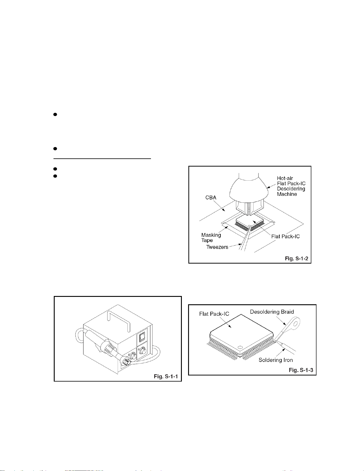
How to Remove / Install Flat
Pack-IC
1. Removal
With Hot-Air Flat Pack-IC Desoldering
Machine:
1. Prepare the hot-air flat pack-IC desoldering
machine, then apply hot air to the Flat Pack-IC
(about 5 to 6 seconds). (Fig. S-1-1)
be melted). (Fig. S-1-6)
4. Release the flat pack-IC from the CBA using
tweezers. (Fig. S-1-6)
CAUTION:
1. The Flat Pack-IC shape may differ by
models. Use an appropriate hot-air flat
pack-IC desoldering machine, whose shape
matches that of the Flat Pack-IC.
2. Do not supply hot air to the chip parts
around the flat pack-IC for over 6 seconds
because damage to the chip parts may occur.
Put masking tape around the flat pack-IC to
protect other parts from damage. (Fig. S-1-2)
3. The flat pack-IC on the CBA is affixed with
glue, so be careful not to break or damage the
foil of each pin or the solder lands under the IC
when removing it.
With Soldering Iron:
1. Using desoldering braid, remove the solder
from all pins of the flat pack-IC. When you use
solder flux which is applied to all pins of the flat
pack-IC, you can remove it easily. (Fig. S-1-3)
2. Remove the flat pack-IC with tweezers while
applying the hot air.
3. Bottom of the flat pack-IC is fixed with glue
to the CBA; when removing entire flat pack-IC,
first apply soldering iron to center of the flat
pack-IC and heat up. Then remove (glue will
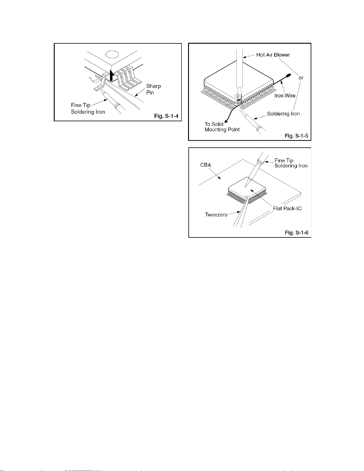
2. Lift each lead of the flat pack-IC upward one
by one, using a sharp pin or wire to which
solder will not adhere (iron wire). When
heating the pins, use a fine tip soldering iron or
a hot air desoldering machine. (Fig. S-1-4)
3. Bottom of the flat pack-IC is fixed with glue
Page 5 of 51
to the CBA; when removing entire flat pack-IC,
first apply soldering iron to center of the flat
pack-IC and heat up. Then remove (glue will
be melted). (Fig. S-1-6)
4. Release the flat pack-IC from the CBA using
tweezers. (Fig. S-1-6)
With Iron Wire:
1. Using desoldering braid, remove the solder
from all pins of the flat pack-IC. When you use
solder flux which is applied to all pins of the flat
pack-IC, you can remove it easily. (Fig. S-1-3)
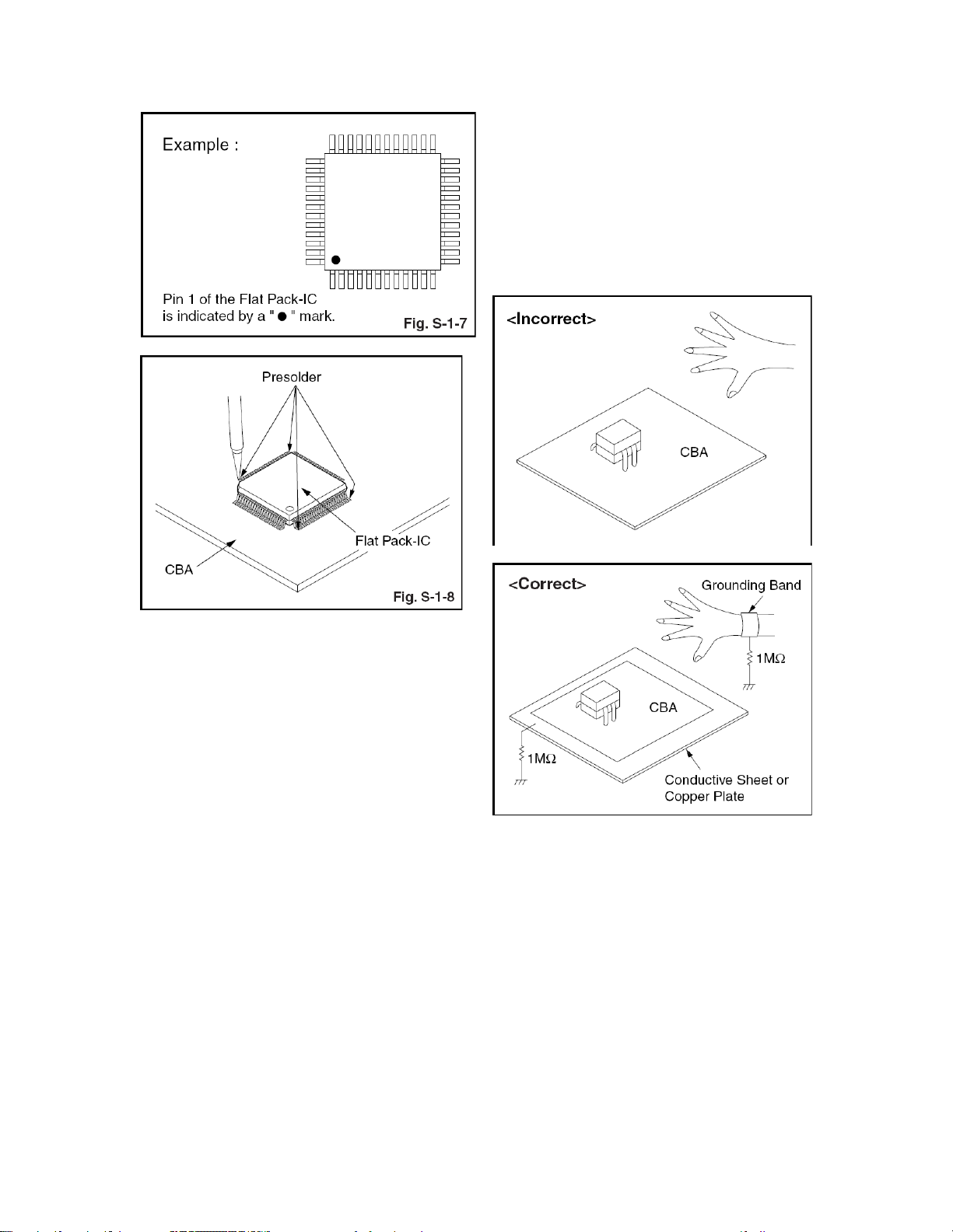
2. Affix the wire to a workbench or solid
mounting point, as shown in Fig. S-1-5.
3. While heating the pins using a fine tip
soldering iron or hot air blower, pull up the wire
as the solder melts so as to lift the IC leads
from the CBA contact pads as shown in
Fig.S-1-5.
4. Bottom of the flat pack-IC is fixed with glue
to the CBA; when removing entire flat pack-IC,
first apply soldering iron to center of the flat
pack-IC and heat up. Then remove (glue will
be melted). (Fig. S-1-6)
5. Release the flat pack-IC from the CBA using
tweezers. (Fig. S-1-6)
Note: When using a soldering iron, care must
be taken to ensure that the flat pack-IC is not
being held by glue. When the flat pack-IC is
removed from the CBA, handle it gently
because it may be damaged if force is applied.
2. Installation
1. Using desoldering braid, remove the solder
from the foil of each pin of the flat pack-IC on
the CBA
so you can install a replacement flat pack-IC
more easily.
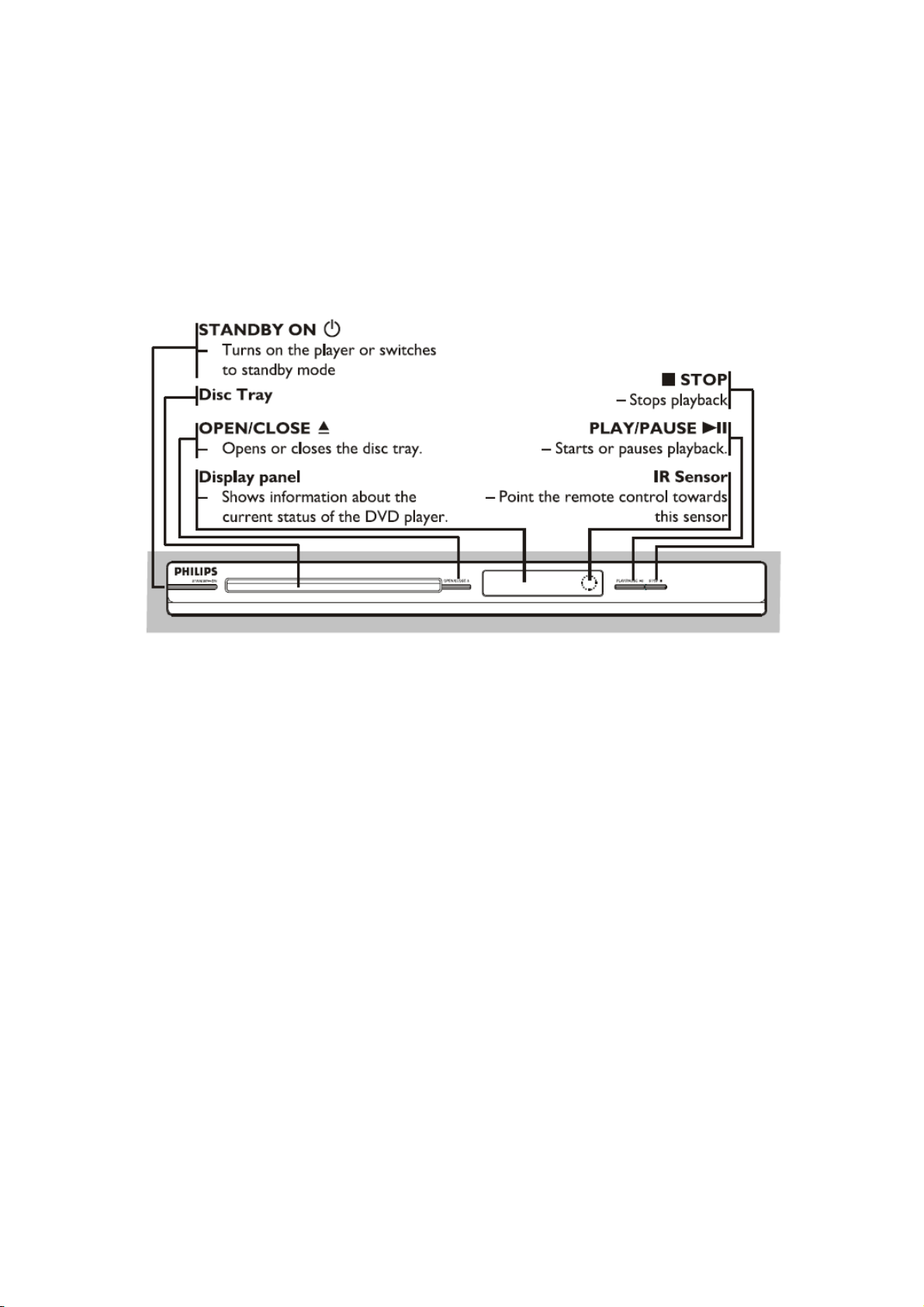
2. The “●” mark on the flat pack-IC indicates
pin 1. (See Fig. S-1-7.) Be sure this mark
matches the 1 on the PCB when positioning
for installation. Then presolder the four
corners of the flat pack-IC. (See
Fig. S-1-8.)
3. Solder all pins of the flat pack-IC. Be sure
that none of the pins have solder bridges.
2. Ground for Workbench
Page 6 of 51
Be sure to place a conductive sheet or copper
plate with proper grounding (1 M∧) on the
workbench or other surface, where the
semi-conductors are to be placed. Because
the static electricity charge on clothing will not
escape through the body grounding band, be
careful to avoid contacting semi-conductors
with your clothing.
Instructions for Handling
Semiconductors
Electrostatic breakdown of the
semi-conductors may occur due to a potential
difference caused by electrostatic charge
during unpacking or repair work.
1. Ground for Human Body
Be sure to wear a grounding band (1 M∧) that
is properly grounded to remove any static
electricity that may be charged on the body.
OPERATING CONTROLS AND FUNCTIONS
Page 7 of 51
Front Panel
Back Panel

Remote Control
Page 8 of 51
DISASSEMBLY INSTRUCTIONS
Page 9 of 51
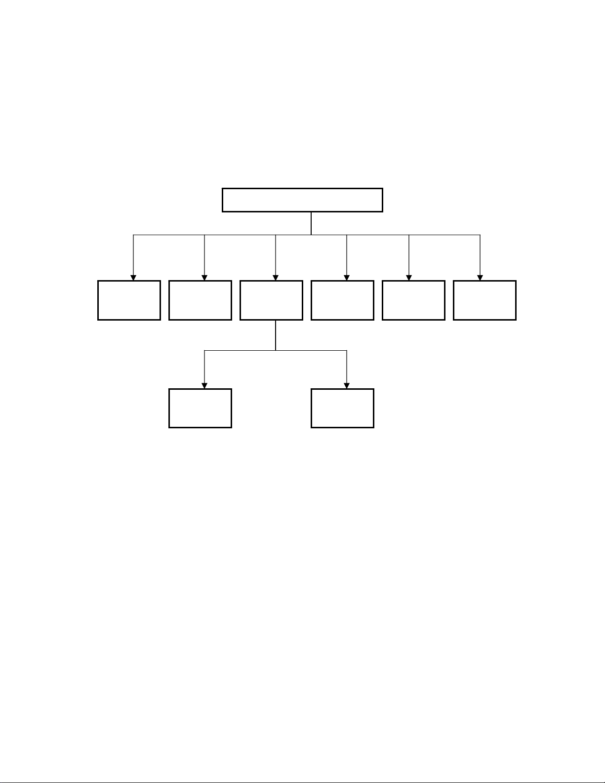
1. Disassembly Flowchart
This flowchart indicates the disassembly steps to gain access to item(s) to be serviced. When
reassembling, follow the steps in reverse order. Bend, route, and dress the cables as they were
originally.
Top Cas e
Loader Main
Board
Standby
Board
Front
Panel
Power
Board
Control
Board
Amplifier
Board
Jack Board
Page 10 of 51
2. Dismantling of top case
2-1. Ensure no disc in the tray and keep tray close, turn off the DVD player and then disconnect the mains supply.
Loosen 5 screws ”A” as shown in figure 2-1.
A
Figure 2-1.
2-2. Take off the top case as shown in figure 2-2.
Figure 2-2.
OPEN
3. Dismantling of control + standby board
Page 11 of 51
3-1. Release the lock “B” at the same time as shown figure 3-1.
PUSH PUSH
B
PUSH
PUSH
Figure 3-1
3-2. Loosen 5 screws “C” as shown in figure 3-2.
C
Figure 3-2

4. Dismantling of loader
Page 12 of 51
4-1. Loosen 3 screws “D” as shown in figure 4-1.
D
Figure 4-1.

5. Dismantling of main board
Page 13 of 51
5-1. Loosen 5 screws as shown in figure 5-1.
E
Figure 5-1.
6. Dismantling of power board
Page 14 of 51
6-1. Loosen 2 screws “F” as shown in figure 6-1.
6-2. With a pincers to nip rubber nail “G” as shown in figure 6-1.
F
Figure 6-1
G

7. Dismantling of amplifier board
Page 15 of 51
7-1. Loosen 1 screw “H” as shown in figure 7-1.
H
Figure 7-1.
 Loading...