

Page 1

Published by Liu BZH 0371 Service BPAVC Printed in the Netherlands Subject to modification EN 3141 785 13763
©
Copyright 2002 Philips consumer Electronics B.V. Eindhoven, The Netherlands,
All rights reserved. No part of this publication may be reproduced, stored in a
retrieval system or transmitted, in any form or by any means, electronic,
mechanical, photocopying, or otherwise without the prior permission of Philips.
DVD-Video Player DVP320 DVP323
Contents Page
1 Technical Specs and Connection Facilities 2
2 Safety Instructions, Warnings, Notes,
and Service Hints 3
3 Directions for User 7
4 Dismantling Instructions and exploded view 21
5 Diagnostic Software, Trouble shooting and Test
Instructions 23
6
Wiring, Block Diagrams
Block Diagram 29
Wiring Diagram 30
7
Electrical Diagrams and Print-Layouts Diagram PWB
Power Supply unit (MITSUMI) 31 32
Power Supply unit (EPM) 33 34
MPEG Board: INDEX 35 41-42
MPEG Board: RF Part 36 41-42
MPEG Board: SERVO and MPEG 37 41-42
MPEG Board: MEMORY 38 41-42
MPEG Board: AUDIO and VIDEO 39 41-42
Front Board 43 44
8 Alignments (Not Applicable) 45
9 Circuit Descriptions (Not Applicable) 45
10 Spare Parts List 49
11 Revision List 57
DVP320B/17 DVP320F/
17
DVP320/
93/78/75/69/00/AK/BK
DVP323/
05
Version 1.3
Page 2
1. Technical specificationsEN 2
DVP320
1 Technical Specifications
DVP320/
93/69/78/75/00
DVP320B(F)/
Specifications
DVD-Video Player
Technical specifications DVD320/
PLAYBACK SYSTEM
DVD Video
Video CD & SVCD
CD
PICTURE CD
MP3-CD
CD-R, CD-RW
DVD+R, DVD+RW
VIDEO PERFORMANCE
CVBS 1Vpp --- 75
Component video Y: 1.00Vpp --- 75
Pr : 0.7Vpp --- 75
Pb: 0.7Vpp --- 75
93/78/69/75/00
17
, DVP320B(F)/17
AUDIO PERFORMANCE
DA Converter 24bit
Signal-Noise (1KHz) 100dB
Dynamic range(1KHz) >90dB
DVD fs 96 kHz 4Hz- 44kHz
SVCD fs 48 kHz 4Hz- 22kHz
CD/VCD fs 44.1kHz 4Hz- 20kHz
TV STANDARD (PAL/50Hz) (NTSC/60Hz)
Number of lines 625 525
Playback Multistandard (PAL/NTSC)
DVP320
fs 48 kHz 4Hz- 22kHz
fs 44.1kHz 4Hz- 20kHz
Progressive scan output except /69, /75
AUDIO FORMAT
Digital Mpeg/ AC-3/ DTS compressed Digital
PCM 16, 20, 24 bits
fs, 44.1, 48, 96 kHz
MP3(ISO 9660) 24, 32, 56, 64, 96, 128,
256 kbps & variable
bit rate fs, 16, 22.05,
24, 32, 44.1, 48 kHz
Analog Sound Stereo
Specifications subject to change without prior notice
CONNECTIONS
Component Video Output Cinch
CVBS Video Output Cinch
Audio Output(L+R) Cinch
Digital Output 1 coaxial
IEC958 for CDDA / LPCM
IEC1937 for MPEG1, MPEG 2,
Dolby Digital and DTS
CABINET
Dimensions (w x d x h) 216 x 216 x 45 mm
Weight Approximately 0.8 Kg
POWER CONSUMPTION
Power consumption <8W
Power consumption in Standby mode <1.2W
Page 3

DVP320
2. Safety Instructions, Warnings, Notes, and Service Hints
2.1 Safety Instructions
2.1.1 General Safety
Safety regulations require that during a repair:
Connect the unit to the mains via an isolation transformer.
Replace safety components, indicated by the symbol ,
only by components identical to the original ones. Any
other component substitution (other than original type) may
increase risk of fire or electrical shock hazard.
Safety regulations require that after a repair, you must return
the unit in its original condition. Pay, in particular, attention to
the following points:
Route the wires/cables correctly, and fix them with the
mounted cable clamps.
Check the insulation of the mains lead for external
damage.
Check the electrical DC resistance between the mains plug
and the secondary side:
1. Unplug the mains cord, and connect a wire between
the two pins of the mains plug.
2. Set the mains switch to the 'on' position (keep the
mains cord unplugged!).
3. Measure the resistance value between the mains plug
and the front panel, controls, and chassis bottom.
4. Repair or correct unit when the resistance
measurement is less than 1 Mohm.
5. Verify this, before you return the unit to the customer/
user (ref. UL-standard no. 1492).
6. Switch the unit ‘off’, and remove the wire between the
two pins of the mains plug.
2.1.2 Laser Safety
This unit employs a laser. Only qualified service personnel may
remove the cover, or attempt to service this device (due to
possible eye injury).
Laser Device Unit
Type : Semiconductor laser
GaAlAs
Wavelength : 650 nm (DVD)
: 780 nm (VCD/CD)
Output Power : 20 mW
(DVD+RW writing)
(DVD reading)
: 0.3mW
(VCD/CD reading)
Beam divergence : 60 degree
Figure 2-1
Note: Use of controls or adjustments or performance of
procedure other than those specified herein, may result in
hazardous radiation exposure. Avoid direct exposure to beam.
2.2 Warnings
2.2.1 General
All ICs and many other semiconductors are susceptible to
electrostatic discharges (ESD, ). Careless handling
during repair can reduce life drastically. Make sure that,
during repair, you are at the same potential as the mass of
the set by a wristband with resistance. Keep components
and tools at this same potential.
Available ESD protection equipment:
– Complete kit ESD3 (small tablemat, wristband,
connection box, extension cable and earth cable) 4822
310 10671.
– Wristband tester 4822 344 13999.
Be careful during measurements in the live voltage section.
The primary side of the power supply (pos. 1005), including
the heatsink, carries live mains voltage when you connect
the player to the mains (even when the player is 'off'!). It is
possible to touch copper tracks and/or components in this
unshielded primary area, when you service the player.
Service personnel must take precautions to prevent
touching this area or components in this area. A 'lightning
stroke' and a stripe-marked printing on the printed wiring
board, indicate the primary side of the power supply.
Never replace modules, or components, while the unit is
‘on’.
2.2.2 Laser
The use of optical instruments with this product, will
increase eye hazard.
Only qualified service personnel may remove the cover or
attempt to service this device, due to possible eye injury.
Repair handling should take place as much as possible
with a disc loaded inside the player.
Text below is placed inside the unit, on the laser cover
shield:
Figure 2-2
2.2.3 Notes
Dolby
Manufactered under licence from Dolby Laboratories. “Dolby”,
“Pro Logic” and the double-D symbol are trademarks of Dolby
Laboratories. Confidential Unpublished Works.
©1992-1997 Dolby Laboratories, Inc. All rights reserved.
Figure 2-3
Trusurround
TRUSURROUND, SRS and symbol (fig 2-4) are trademarks of
SRS Labs, Inc. TRUSURROUND technology is manufactured
under licence frm SRS labs, Inc.
Figure 2-4
CAUTION VISIBLE AND INVISIBLE LASER RADIATION WHEN OPEN AVOID EXPOSURE TO BEAM
ADVARSEL SYNLIG OG USYNLIG LASERSTRÅLING VED ÅBNING UNDGÅ UDSÆTTELSE FOR STRÅLING
ADVARSEL SYNLIG OG USYNLIG LASERSTRÅLING NÅR DEKSEL ÅPNES UNNGÅ EKSPONERING FOR STRÅLEN
VARNING SYNLIG OCH OSYNLIG LASERSTRÅLNING NÄR DENNA DEL ÄR ÖPPNAD BETRAKTA EJ STRÅLEN
VARO! AVATTAESSA OLET ALTTIINA NÄKYVÄLLE JA NÄKYMÄTTÖMÄLLE LASER SÄTEILYLLE. ÄLÄ KATSO SÄTEESEEN
VORSICHT SICHTBARE UND UNSICHTBARE LASERSTRAHLUNG WENN ABDECKUNG GEÖFFNET NICHT DEM STRAHL AUSSETSEN
DANGER VISIBLE AND INVISIBLE LASER RADIATION WHEN OPEN AVOID DIRECT EXPOSURE TO BEAM
ATTENTION RAYONNE MENT LASER VISIBLE ET INVISIBLE EN CAS D'OUVERTURE EXPOSITION DANGEREUSE AU FAISCEAU
0.8 mW
:
2.Warnings, lasersafety instructions and notes EN 3
Page 4

2. Warnings, lasersafety instructions and notesEN 4
2
2
2
2
2
.3 Service hints
.3.1. Handling chip components
DVP320
.3.2. Repair tips
.3.2.1. Switched mode power supply
.3.2.2. DVD Loader
The power supply unit has to be replaced in case of failure. The schematic diagram provided in the service manual is only for
information and no service parts will be available.
The DVD Loader is a non-repairable unit and in case of failure, it has to be replaced with a complete DVD Loader.
Because DVD Loaders are very sensitive to ESD. During replace, must obey the following rules.
Preparations
1. Must wear ESD Wrist Belt
2. All the repair tools (equipments) must connect with ground
3. Ensure the Servo (MPEG) board connect with ground
Demounting
1. Remove the 4 screws item 214 (refer to explode view)
2. Solder the ESD protect point on the defect loader before unplug the cables between Loader and Mpeg board. The position of the
ESD protect point shows in the photo 1
3. Pack the defect loader for analyse if necessary.
Page 5

DVP320
2
2
p
2
Mounting
1. Ensure the cables between a new Loader KHM-280AHA and Mpeg board connect well.
2. Unsolder the ESD protect point on the new Loader KHM-280AHA use a soldering iron with ESD protect carefully.
3. Mantling the Loader.
2.Warnings, lasersafety instructions and notes EN 5
8 pins cable
Photo 1: Position of ESD protect-point (Bottom view) Photo 2: 8Pins cable is easily hurt
.3.2.3. Mpeg board and Front Display
Generally the Mpeg board and front display are non-repairable units and in case of failure, they have to be replaced with a completely
too. However if necessary they can be repaired down to simple component level. These simple components include power circuit,
.3.2.4. Important Notes
quartz circuit, servo driver, Flash, switches, LEDs, cables etc.
1. Be aware that Item 8002 (8 pins cable 314101021911) is easily hurt by a screw during assembling the cabinets. Refer to wiring
diagram and the above photo 2.
2. The procedures to remove the top mpeg shield.
Ste
1: unlock the two locks in the side near PSU Step 2: Remove the locking tap
Step 3: Remove the locking tap near left side Step 4: Remove the top shield
.3.3. Chan ge o f Software setting
The software setting can be change according to the following procedure:
1. Press < OPEN/CLOSE> switch lock on the door to open the door.
2. Enter the 4-digit code <9> <9> <9> <9> on the remote control.
3. Enter one of the keys below to change the software setting.
Page 6

2. Warnings, lasersafety instructions and notesEN 6
2
2
2
2
DVP320
REGION CODE USA Î 1
<SUBTITLE><0> Set to setup configuration of DVP320B/17 and DVP320F/17
<SUBTITLE><1> Reserved
<SUBTITLE><2> Set to setup configuration of DVP320/93
<SUBTITLE><3> Set to setup configuration of DVP320/69
<SUBTITLE><4> Set to setup configuration of DVP320/75
<SUBTITLE><5> Set to setup configuration of DVP320/78
4. The change should effect immediately with information indicated on TV screen.
Note: When changing the set-up configuration, the change will take immediate effect with the information indicated on the TV
screen for a short period.
.3.4. Software upgrade via Download disc
Both the application and servo software are delivered in one SW stack and it can be flashed into the DVD player by means of a
CD-ROM disc. The CD-ROM disc has to be made with a CD writer SW.
.3.4.1. Software upgrade procedure
Note:
1) The file name used for writing on the CD-R/RW MUST
2) For better and fast reading, add one big garbage file of 50-100MB.
1) Open disc door on the player.
2) Put the DOWNLOAD DISC into the player and close disc door.
3) The upgrading operation will start automatically.
4) The Play_LED will blink (turn ON and OFF).
5) The upgrading will take approximately about 1 minute.
6) Take out the upgrade disc when the Play_LED stop blinking.
EUROPE Î 2
AP Î 3
LATAM Î 4
INDIA / RUSSIA Î 5
CHINA Î 6 (or 0)
be in UPPER CASE. e.g.: GAP.BIN
Important note:
Do not power off or interrupt the mains during the upgrading else the player's flash memory will be erased.
.3.5. Verify setting
To check that the setting has change successfully.
1. Press <DISPLAY> button on the remote control while disc tray is open.
2. Two lines text will appear on the TV screen. That is how it looks like.
GAP542PH-030812-320-171U
SERVO:001FC74 REG:1
In text, the following numbers refer to:
SD542PH-030812 Î refer to Application software version
•
REG 1 Îrefer to region code
•
SERVO:001FC74 Î refer to servo software version
•
320-171 Î refers to set-up configuration of a type number,eg. DVP320/17
•
.3.6. ComPair
There is no ComPair available.
Page 7

3. Directions for use
Disc will continue to spin for a few seconds. Do
not allow children to remove the Disc. Wait for
the Disc to stop spinning completely before you
reach to remove the Disc or touch the Disc.
temperature or humidity.
to a warm location, or is placed in a very damp
room, moisture may condense on the lens of the
disc unit inside the DVD player. Should this occur,
the DVD play er would not operate normally.
Leave the power on for about one hour with no
disc in the DVD player until normal playback is
When you open the Disc compartment lid, the
Do not expose your player to extremes of
If the DVD player is brought directly from a cold
DVP320
Some discs limit certain functions during
Helpful Hints!
playback (eg fast forward is not working at
the beginning of certain discs). This is
nomal behaviour because the disc
determines the way in which you can
possible.
lubricating bearings and must not be oiled or
lubricated.
mode, it is still consuming some power. To
disconnect the system from the power supply
completely, remove the plug from the AC Outlet.
Symbols Used in this Booklet
The below symbols appear in some headings and
notes with the following meanings:
The mechanical parts of the set contain self-
When the DVD player is switched to Standby
interact with its content.
3.Directions for use EN 7
Thank you for pur chasing this Philips DVD player.
This Ownerís Manual explains the basic operation
of this DVD player.
Introduction
Contents
Picture CD & MP3 CD Playback
General Operation...................................13
MP3 & JPEG Navigator...........................................13
Environmental Information
All unnecessary packaging has been omitted. We
have tried to make the packaging easy to separate
into three materials: cardboard (box), polystyrene
foam (buffer) and polyethylene (bags, protective
foam sheet).
Your DVD player consists of materials which can
be recycled and reused if disassembled by a
specialized company. Please observe the local
regulations regarding the disposal of packaging
Play Mode.................................................................13
Special JPEG Features..............................14
Function Introduction............................................14
Preview Function.....................................................14
Zoom picture ..........................................................14
Playback with multi-angles ...................................14
Wipe T ype.................................................................14
Special MP3 Features..............................14
Function Introduction............................................14
JPEG and MP3 Simultaneous Playback...14
Setup menu
...7
materials, exhausted batteries and old equipment.
Package Contents
ñ DVD-Video player
ñ Remote control with lithium battery
ñ One set of audio cables (red/white)
ñ One set of video cable (yellow)
ñ Mains Cord
ñ Ownerís Manual
General Setup menu ...............................15
OSD language .........................................................15
Program ..............................................................15-16
Disc Lock .................................................................16
Screen Saver ............................................................16
Analog Audio Setup menu ......................17
DOWNMIX.............................................................17
D.R.C ........................................................................17
SOUND MODE .....................................................17
3D SOUND.............................................................18
Digital Audio Setup menu........................18
operating voltage indicated on the typeplate is
Safety Information
Before operating the DVD player, check that the
Digital Output..........................................................18
LPCM Output..........................................................18
Video Setup menu....................................19
TV T ype .....................................................................19
identical with the voltage of your local power
supply. If not, please co nsult your dealer .
surface.
for ventilation. Leave room above the Player for
the Disc compartment lid to open completely.
space all around the player for adequate
ventilation.
Place the DVD player on a flat, hard and stable
Allow about one inch of space around the Player
In a cabinet, allow about 2.5cm (1 inch) of free
Always close the Disc compartment lid on top of
TV Display ...............................................................19
Progressive Scan......................................................20
Closed Captions......................................................20
Smart Picture..........................................................21
Picture Setting..........................................................21
Preference Setup menu ..........................22
Audio language .......................................................22
Subtitle language .....................................................22
Disc Menu language ...............................................23
Parental Control ....................................................23
Default Setup...........................................................24
MP3/JPEG Navigator .............................................24
nside the Disc compartment).
the Player to keep dust off the lens (which is
i
compartment. A damaged lens could hinder Disc
playability. Electrostatic discharge could damage
the unit permanently.
Do not touch the lens inside the Playerís Disc
Password ...................................................24
Specifications
Specifications ...........................................................25
Maintenance
Maintenance ........................................................ 25
Troubleshooting
Troubleshooting ....................................................26
4
3
Language Code
Language Code..................................................27-28
Connecting to a TV with audio cable and
Introduction
Environmental Information .......................................4
Supplied accessories ..................................................4
Safety Information ......................................................4
Symbols Used in this Booklet ..................................4
Functional overview
Top and Rear Panel ....................................................5
Remote Control .........................................................6
Preparation
component video cable..............................................7
Before you begin ........................................................7
Connecting to a TV with audio and video cables
Connecting to a TV and a two-channel
Stereo.............................................................................7
Connecting to a TV and a Stereo.............................7
Replacing battery (lithium CR2025) into the
remote control...........................................................8
Using the Remote Control ......................................8
Connecting the Power Supply...................................8
Switching On ...............................................................8
Smart Power On/Off..................................................8
Operation
Basic Playback ..............................................9
General Operation ......................................9
Video control during playback .................................9
Audio control during playback ................................9
Repeat/Shuffle ..............................................................9
Repeat A-B .............................................................10
Virtual Remote Control.........................................10
5 disc Resume .........................................................10
OSD (On-Screen Display).....................................10
Zoom ........................................................................11
Special DVD Features .............................11
Playing a Title .........................................................11
Playing a Chapter ...................................................11
Smart Play....................................................................11
Camera Angle .........................................................11
Changing the Audio Language ...........................11
Subtitles ....................................................................11
Special VCD & SVCD Features ...........11-12
Playback Control (PBC) ........... ................ ........11
Preview Function ...................................................12
Page 8

0-9 numerical key pad
Press to select numbered items in a
DVP320
men u. Press to se l ect a Cha p te r,
Title, or Track to play.
T
Press to skip to th e n ex t Cha pte r or
Track. Press and hold to activate the
DISPLAY
Press d uri ng p lay b ack t o se e
current di sc in fo rma tio n on the TV
screen.
SYSTEM MENU
Press to a cce ss or remo ve th e
Setu p M e nu o f th e DVD Pl ayer.
Smart Play function.
PAUSE ( ; )
Press to p au se p lay or to a d va n ce a
paused picture one frame at a time.
AUDIO
Press to se le ct a d iff ere nt au d io
language or soundtrack during
DVD playback. With some Video
CDs, Supe r Video CD s, and Aud io
CDs, press AUDIO to ch o ose a n
audio channel.
ZOOM
Press to red uce o r en la rge th e
picture during playback.
PREVIEW
Press to enter the Preview menu
for a Video CD or Super Video
CD. O r, press to p lay the first
seve ral se co n ds of ea ch Track o n
an Audio CD .
MUTE
Press to sile n ce or resto re th e
volume.
3. Directions for useEN 8
POWER B
Press to sw itch S ta nd b y m od e.
Functional Overview
Functional Overview
OK
VCD disc
1 2 3 4
DISC MENU
RETURN / TITLE
Remote Control
availab le with all D iscs.
menu. T hese options are not
Press to go to a p re vio us D isc
menu o r to acc e ss a DVD ís Ti tle
disc /switch PBC on or off for
Press to acc e ss m en u o f a DVD
Press to sel ect ite m s in a m e nu .
Press to a p pro ve a m e nu se le ctio n.
S
ANGLE
PLAY ( B )
SUBTITLE
Press to b e gin D isc p lay b a ck
Press to se le ct su b tit le lan g ua g e
STOP ( 9 )
Virtual Remote on screen.
Press 3 or 4 for slow mo tio n.
Press 1 o r 2 fo r fa st se a rchin g.
current Cha pte r or Track or to
Press a nd h old to d isp lay the
the p reviou s Cha pte r or Tra ck.
Press to sto p Disc p lay b ack.
Press to go to the b eg inn ing of the
REPEAT
on Page 10.
during DVD play.
Press to se le ct a ca m era a ng le
REPEAT (A-B)
or Disc re p ea te d ly. Details a re
Press to p lay a Ch a p te r, Title, Track,
repeatedly.
segment of the Disc play s
Press to se t up Re p e at A-B
play b ack, in wh ich a ce r ta in
6
5
cord
Mains Socket
ñ con ne ct to p o we r
b Pr)
STOP
ñ stop p lay b a ck
PLAY /PAUSE
ñ star t/in te rrup t play b ack
VIDEO
inputs
ñ con ne ct to a TV with com p o ne nt vid e o
Video out (Y P
Video out (CVBS)
ñ con ne ct to a TV with CVBS in p uts
Top and Rear Panels
coaxia l inp uts
Coaxial output
ñ con ne ct to a rece i ve r with
AUDIO OUT (Left/Right)
ñ con ne ct to AUD IO in p ut s of an
AUDIO
COAXIAL VIDEO Y Pb Pr
LR
system
ER
POW
ote sensor
Rem
toward your TV).
tray
ñ switch DVD on or off
amp lifier, rece iver or stereo
OPEN/CLOSE
ñ open/close the disc
Caution:
Do not touch the inner pins of the sockets on the rear panel. Electrostatic discharge
may cause permanent damage to the unit.
Do not touch the lens inside the Playerís Disc compartment. A damaged lens could
the Playe r, p oint th e rem ote he re ( not
Rece ive th e co m m a nd s f rom t he DVD
Playerís remote control. When using the
DVD Pl ayerís remote co ntrol to operate
hinder Disc playability. Electrostatic discharge could damag e the unit permanently.
Page 9
DVP320
3.Directions for use EN 9
Switching On
Be sure that the DVD player has been correctly
connected to the TV and audio equipment.
2 Switch on the TV and DVD player.
1
Replacing battery (lithium
CR2025) into the remote control
Pull out the lithium battery
Preparation
1
Preparation
Connecting to a TV and a two-
channel Stereo
3 Set the TV to the correct Video In channel. (eg.
3V CR2025
---
LITHIUM BATTERY
DC
compartment.
Back of TV
(example only)
Stereo
(example only)
EXT1, EXT2, A V1, AV2, AUDIO/VIDEO, etc.
5
2
0
2
+
3V
R
C
the battery compartment back to the
2 Replace a new battery and fully insert
appears on the TV.
Please refer to your TV owner's manual for
details.)
The player display lights and the default screen
system or receiver), turn it on and select the
appropriate input source for the DVD player
output. Refer to the equipment ownerís manual
for detail .
Smart Power On/Off
When in STOP or NO DISC mode, the DVD
player will switch to standby mode after 15
minute s without any operations fo r saving energy.
It is easily reactivated by pressing the POWER or
PLAY key on the remote control or the PLAY
button on the front panel.
About Progressive Scan
If your TV set has the Progressive Scan, please
connect the Y/Pb/Pr VIDEO OUT jacks on the
DVD player to the corresponding jacks on the TV
set with the component video cables (no
supplied). After connection, please activate the
PROGRESSIVE function of the DVD player. Refer
to the chapter Progressive Scan for more details.
Deactivating Progressive Scan
If you have activated the PROGRESSIVE function,
however, your TV set doesnít have the function
actually, or the component cable doesnít be
correctly connected, the TV set will not display
normally. You can deactivate the function as
follows:
turn on the DVD player.
compartment lid on top of the player.
DVD player will restore the interlace video
output.
4 If you are using an external equipment (eg. audio
CR2025
+
CAUTION!
ñ Insert the plastic protective sheet if they
are exhausted or not to be used for a long
time.
ñ Batteries contain chemical substances,
so they should be disposed off properly and
original position.
kept away from children.
3V CR2025
---
LITHIUM BATTERY
DC
Note: When the DVD player is switched to
Standby mode, it is still consuming some power. If
which is used to keep the lithium
battery fresh.
remote sensor of the DVD player.
control a shock.
hot or humid places.
Using the Remote Control
Pull out the plastic protective sheet
Direct the remote control at the
Do not drop or give the remote
remote control.
Connecting the Power Supply
into the power connector on the rear of the
player.
Do not leave the remote control in extremely
Do not spill water or put anything wet on the
1 Plug the female end of the power cable supplied
2 Plug the male end of the cord into an AC outlet.
you wish to disconnect your player completely from
the mains, withdraw the plug from the AC Outlet.
1 Press the POWER button on the front panel to
2 Press OPEN/CLOSE to release the disc
3 Press the 1 , and then press the MUTE key.
8
7
VIDEO IN
MAINS
120V ~ 60HZ
VIDEO
VIDEO IN
AUDIO
COAXIAL VIDEO Y Pb Pr
LR
LEFT AUDIO IN
RIGHT AUD IO IN
the corresponding CVBS VIDEO IN jack on
your TV (cable supplied).
DVD player to the corresponding AUDIO IN
jacks on stereo system by using audio cables
(supplied). Match the cable colors to the jack
colors.
Connecting to a TV and a
Stereo
Connect the VIDEO jack on the DVD player to
Connect the AUDIO OUT (Left/Right) on the
VIDEO IN
MAINS
120V ~ 60HZ
Back of TV
(example only)
AV Receiver
VIDEO
VIDEO IN
A
U
DIO
COAXIAL
DIGITAL
AUDIO IN
COAXIAL VIDEO Y Pb Pr
LR
player to the corresponding VIDEO IN jack on
your TV by using composite video cable (cable
supplied) or component video cable (not
supplied).
player to the corresponding DIGITAL AUDIO
IN jack on your AV Receiver (cable not
Connect the VIDEO OUT jack on the DVD
Connect the COAXIAL jack of the DVD
t the DVD player directly to your
supplied). In this case, do not use the player's
audio left and right output.
Warning!
ñ Connec
TV, instead of eg. a VCR, to avoid
distortion because DVD video discs are
copy protected.
ñ Do not connect the DVD player AUDIO
.Check the Stereoís manual to be
TM
ñ Set DIGITAL OUTPUT correctly. The
Stereo must support MPEG2 or Dolby
sure.
Digital
OUT to PHONO IN of your player.
Before you begin...
or other devices. Not e the style of jacks and
connectors on the other equipment. Determine
Refer to the instructions of your TV, VCR, Stereo,
Y
Pb/Cb
RIGHT
AUDIO IN
LEFT
LEFT AUDIO IN
VIDEO IN
RIGHT AUDIO IN
MAINS
120V ~ 60HZ
V
IDE
Back of TV
LEFT AUDIO IN
RIGHT AUD IO IN
(example only)
Connecting to a TV with audio
how to choose different Audio and Video In
channels/sources on your other equipment.
Connect equipment to power only after hooking
up everything. Never make or change
connections with equipment connected to power.
Disconnect all equipment from the power outlets.
Please refer to the below choices we introduce
and video cables
to you and select either one of them.
O
VIDEO IN
AUDIO
COAXIAL VIDEO Y Pb Pr
LR
Connecting to a TV with audio
the corresponding CVBS VIDEO IN jack on your
TV (cable supplied).
DVD player to the corresponding AUDIO IN
jacks on TV by using audio cable (supplied). Match
Connect the VIDEO jack on the DVD player to
Connect the AUDIO OUT (Left/Right) on the
cable and component video cable
the cable colors to the jack colors.
AUDIO IN Pr/Cr
MAINS
120V ~ 60HZ
V
IDE
Back of TV
(example only)
Pr/Cr
Pb/Cb
LEFT
AUDIO IN
RIGHT
AUDIO IN
O
Y
AUDIO
COAXIAL VIDEO Y Pb Pr
LR
nnect the Y/Pb/Pr VIDEO OUT on the DVD
player to the corresponding jack on your TV by
using component video cable (not supplied).
Match the cable colors to the jack colors.
DVD player to the corresponding AUDIO IN
jacks on TV by using audio cables (supplied).
Match the cables color to the jack colors.
Co
Connect the AUDIO OUT (Left/Right) on the
Page 10
3. Directions for useEN 10
DVP320
OSD (On-Screen Display)
This function will provide some information about
your playing disc on the screen.
Note: If you want to use this funciton in VCD discs,
REPEAT until all the repeat and shuffle modes
disappear fro m the TV scr een.
Operation
3 To cancel repeat or shuffled playback, press
Title/Chapter/Track Selection
1 Press 3 4 to select TITLE, CHAPTER or
0 Press DISPLAY k ey on the remote control.
please set PBC off firstly.
Repeat A-B
DVD-Video Discs: repeat a sequence in a
TRACK.
Chapter, or Track number you want.
DVD player will playback selected title.
2 Press OK.
3 Press the numerical keys to enter the Title,
title or chapter
Video and Audio CDs: repeat a sequence in a
track
point.
1 Press REPEAT A- B at your chosen starting point.
2 Press REPEAT A- B again at your chosen end
Time Search
3 4 to highlight a display ty pe, then press OK.
The selected display type and its counter will
appear at the bottom of the display.
The following display types will be available,
depending on t he Disc in the Player.
For DVD discs:
CHAPTER ELAPSED - elapsed playing time of
current Chapter;
CHAPTER REMAIN - remaining playing time of
current Chapter;
TITLE ELAPSED - elapsed playing time of current
Title;
TITLE REMAIN - remaining playing time of
curre nt Title.
For VCD/SVCD discs:
TOTAL ELAPSED - elapsed playing time of
curre nt D i sc ;
TOTAL REMAIN - remaining playing time of
curre nt D i sc ;
SINGLE ELAPSED - elapsed playing time of
curre nt Tr ack;
SINGLE REMAIN - remaining playing time of
curre nt Tr ack.
TIME, CH TIME, TRACK TIME or DISC TIME.
playing time at which you want to resume
playback.
Enter the time in hours, minutes, and seconds.
Play will start at that point.
Press 1 to quit and reselect TT TIME, CH TIME,
TRACK TIME or DISC TIME.
1 Press 3 4 to select TIME DISP. Press OK. Press
Forward
Slow Motion
Next Chapter/
Track
Pause
Forward Search
Camera Angles
Virtual Remote will be displayed at the down left
corner of the screen. Press 341 2 to select a
button in the virt ua l remote, and then press OK
in the real remote to activate the buttonís
function.
The repeat sequence begins.
Virtual Remote Control
3 To exit the sequence, press REPEAT A-B.
Frame-by-Frame
Reverse Slow
Previous
Motion
Chapter/Track
Reverse Search
0 Press and hold °1 key during playback. Then a
Subtitles
Audio language
When you activate Virtual Remote Control,
you also can use the real remote control to do
2 Press OK to select the time counter beside TT
3 Press the numerical keys to enter the elapsed
s, even if the disc was ejected or the DVD
any operation.
When you activate Virtual Remote Control,
341 2 keys will not be used to search time.
5 Disc Resume
This player can resume playback of the last 5
disc
disc. If the information of this disc has been
stored in the memory of DVD player, it will be
player i s in Standby mode.
1 Load one disc, which is one of the last 5 discs.
played back from the stop point last time.
2 Press PLAY when DVD player is recognizing the
10
9
Operation
4.
To get a slow motion effect during playback, press
1
2 To selec t different searching speeds , press 4 again.
Basic Playback
Press POWER on the top panel to turn on the
DVD player. Turn on your TV. Set it to the correct
Video In channel.
1
NOTE:
- The SLOW BACKWARD function is not available
for Super VCD/VCD discs.
Audio control during playback
3 Pres s the PLAY key to return to normal play back.
the disc compartment.
facing up and then press the lid down.
After recognizing the disc, the player will start
to playback automatically.
2 Press OPEN/CLOSE on the top panel to open
3 Place the Disc on the Disc hub, with the label
MUTE
before you reach to remove the Disc or touch
4 Wait for the Disc to stop spinning completely
Audio channel selection
are used for the audio language selection.
1 Press the MUTE key to disable the sound output.
2 Press the MUTE key again to deactivate mute.
the Disc.
Notes:
ñ DVDs may have a region code. Your player will
1 Super VCD has two stereo audio channels which
not play discs that have a region code different
from the region code of your player.
ñ If ëDisc Lockí is set to LOCK and the disc
select the audio channels you want.
select STEREO, LEFT MONO, RIGHT MONO or
MIX-MONO by pressing the AUDIO key on the
remote control.
STEREO: Output the left and right audio
channels of the disc through the left and right
2 Press the AUDIO key on the remote control to
3 VCD has only one stereo audio channel, you can
inserted is not authorized, the 6-digit code must be
entered and/or the disc must be authorized (see
ëDisc Lockí).
Note: All instructions set out below refer to the
remote control, unless otherwise stated.
General Operation
audio sockets accordingly.
MONO LEFT: Output the left audio channels
Video control during playback
Note: If you choose digital audio output and set
DIGITAL OUTPUT to ALL, you can not select LEFT
of the disc through the left and right audio
sockets.
MONO RIGHT: Output the right audio
channels of the disc through the left and right
audio sockets.
MIX MONO: each of the audio sockets can
resume from the point at which you stopped by
pressing the PLAY key. If you pressed the STOP
STOP/PLAY
key twice, the player will start from the beginning
1 If you press the STOP key once, you can later
MONO and RIGHT MONO with the AUDIO key.
output the same audio effect as stereo.
of the disc.
PAUSE
Repeat/Shuffle
playback.
1 To get a still picture, press PAUSE key during
2 To step forward to the next frame picture, press
PAUSE key again. (This is not available for CD.)
3 To resume normal playback, press PL AY.
You may play a Chapter, Track, Title, or entire Disc
repeatedly.
1 During disc playback, press REPEAT to choose a
SEARCH
1 To search the contents in fast speed, press the 2
Repeat option.
DVD disc: You can choose TITLE or CHAPTER,
which means repeat playing the Title or Chapter.
VCD disc: You can choose TRACK or ALL,
which means repeat playing the Track or the
whole disc.
REPEAT. The Tracks, Chapters, and/or Titles will
play in random order (SHUFFLE) instead of the
order recorded (1, 2, 3, etc.). If you choose
SHUFFLE REPEAT, all the Tracks, Chapters, and/or
Titles will play in random order repeatedly.
2 Press REPEAT to choose SHUFFLE or SHUFFLE
or1 for fast forward/bac kward searching.
or1 again.
Slow Motion
2 To select different searching speeds, press the 2
3 Press PLAY to return to normal playback.
repeatedly.
3 or4.
1 To get a slow motion effect during playback, press
2 To select different searching speeds, press 3 or 4
3 Press PLAY to return to normal play back.
Page 11

2 Disc Interval
If you select DISC INTERVAL, the Disc contents
DVP320
will be divided into six segments. This helps you
previ ew the contents of the entire Disc.
- To start playing the Disc from a certain interval,
press 341 2 to go to the SELECT line in the
display at the bottom of the screen.
- Press the numerical keys to choose a segment
If you select TRACK INTERVAL, the current Track
will be divided into six parts. This helps you see
the contents of the current Track.
(1-6), then press OK to start play from that point.
3 Track Interval
- To play the Track from a certain interval, press
3 4 1 2 to go to the SELECT line.
- Press the numerical keys (1-6) to choose a
segment, then press OK to start play from that
point.
3.Directions for use EN 11
menu.
Preview Function
Operation
0 Press the PREVIEW key to enter previewing
0 Press 34 key to highlight TRACK DIGEST, DISC
Operation
Camera Angle
Some discs contain scenes which have been shot
simultaneously from various angles.
This DVD player allows you to select the desired
To quit preview function: Press 341 2 to
highlight EXIT and press OK to confirm.
To return to the previewing menu for selecting
the othe r digest ty pe: Press 3 4 1 2 t o highlight
DVD is recorded with multi-language audio tracks.
MENU and press OK to confirm.
Subtitles
0 Press SUBTITLE repeatedly to select the different
INTERVAL or TRACK INTERVAL.
0 Press OK key to open one option.
NOTE: The function is available only for the DVD
discs which have several angles recorded .
camera angle.
0 Press the ANGLE key on your remote control.
0 After you enter the menu of any digest type,
NOTE: The function will be activated only if the
languages.
Changing the Audio Language
0 Press AUDIO repeatedly to select the different
If you select TRACK DIGEST, the first five seconds
of each Track will play. This introduces you to the
contents of each Tr ack on the Disc.
1 Track Digest
NOTE: The function will be activated, only if the
subtitles.
DVD or Super VCD is recorded with multi-subtitles.
subtitle on or off.
0 Press SUBTITLE for about 2 seconds to switch
Special VCD & SVCD Features
Playback Control (PBC)
PBC function allows you to enter the index menu
- To choose your desired track, please press 341 2
to go to the SELECT line in the display at the
which is used to select a track after loading the
VCD & SVCD disc.
If you want to activate the function during
the playback or after pressing the STOP
key twice,
2ô on the remote.
bottom of the TV screen. Press the numerical
keys to enter the Track you want.
To see other Tracks, press Previous °1 or Next
- Press the OK key to start playback.
NOTE:
- The content of the index menu depends on the
disc. Please refer to the discís instructions for
details.
- If the disc doesn't include the PBC information,
to set the PBC On.
Pay attention to the hint on the screen.
like.
If the items of the index menus are numbered,
press the appropriate numerical key on the
remote control.
press the OK key to confirm.
during the playback.
1 press the DISC MENU key on the remote control
2 Use the °1 or2ô key to select the page you
3 Press the RETURN key to enter the index menu
this function will have no effect.
If you want to skip the index menu and
playback directly from the beginning,
1 press the DISC MENU key on the remote control
12
11
to switch off the function.
Zoom
You can reduce or enlarge the video image during
2ô key to make a change.
NOTE: This function is NOT available for some
make t he picture two, three, or four times larger.
Or, keep pressing ZOOM to reduce the picture
to 1/2, 1/3, or 1/4 its normal size.
Press 341 2 to move around in the enlarged
playback.
1 Press ZOOM repeatedly during Disc playback to
picture.
2 To return the picture to regular size, press ZOOM
DVD discs.
until the picture returns to its normal size.
Special DVD Features
Playing a Title
A DVD disc may have one or more titles. This
depends on the content (a movie, video clips, a
drama series, etc.) on the disc.
content shows on the screen waiting for your
selection. You can also press the TITLE key on the
remote control to turn back to the title menu
during playback.
Press the appropriate numerical key or 341
2 keys on the remote control to highlight your
0 After you load a disc, information about the
Playing a Chapter
When you have selected a title, it may include
selection.
Press the OK key to confirm.
one or more chapters.
during playback, press DISC MENU key to turn
back to the chapter menu (If disc has chapter
menu).
Press the appropriate numerical key or 341
2 keys on the remote control to highlight your
selection.
Press the OK key to confirm.
0 Any time you want to watch another chapter
Smart Play
Some DVDs start play with movie previews,
advertisements, o r other theatrical trailers. To skip
After a chapter has been selected, you also can
press the °1 or
these and play the main feature, use Smart Play.
0 After one DVD disc is loaded and the DVD
Note: Some DVD discs will not be available for this
the 2ô key until the SMART PLAY is displayed.
function.
The movie content will be played back directly.
VIDEO is displayed on the screen, press and hold
Page 12

3. Directions for useEN 12
Playback with multi-angles
When displaying one picture on TV screen
3 key: Flip the picture vertically.
0 Press the 3 4 1 2 key to get different effects.
DVP320
choose how the pictures will transfer in/out
during play. The default setting is RANDOM.
4 key: Flip the picture horizontally.
Wipe T ype
1 key: rotate the picture anti-clockwise.
2 key: rotate the picture clockwise.
0 Press ANGLE repeatedly during JPEG play to
Special MP3 Features
Function Introduction
ìMP3î stands for ì MPEG Audio Layer-3î and is a
part of the MPEG standard. A CD can store up to
10 hours of MP3 audio, which is nearly 10 times
as much as an Audio CD. Each song is recorded
as a file. You can choose any general function
introduced in GENERAL OPERATION. You can
also c hoose dif ferent playback speeds.
MP3 CD without Jpeg pictures, you can choose
WITHOUT MENU in the MP3/JPEG NAV menu.
playback.
playback at two, four, eight, 16, or 32 times the
normal playback speed, press 2 or 1 key .
0 T o automaticall y playback MP3 after loading a
0 To stop the track, press STOP key during
0 T o fast forward or fast rev erse the track during
0 T o selec t next or previous track, press 2ô or ° 1
key.
JPEG and MP3 simultaneous
playback
Start playing the MP3 file as described above.
1
to stop JPEG playback. Then press STOP to stop
MP3 playback.
2 Select a JPEG for playback as described above.
3 To stop simultaneous playback, press DISC MENU
Picture CD & MP3 Playback
Picture CD & MP3 Playback
Special JPEG Features
Function Introduction
Picture CD is a disc with a collection of JPEG
Play Mode
Playback Selection
file plus one to play the file at any time during
0 One way is to press the number of your favourite
Note: When the Jpeg Zoom function is activated,
some keys like SYSTEM SETUP, PLAY, etc. can not
and pres s OK to playback. Or,
bottom of the screen, then press OK. This will
start playback at the first picture on the current
pictures. You will see the thumbnails of 12 pictures
on the screen.
format pictures, and all extension filenames should
end with 'JPG'. The CD c an be recorded on any
computer, and pictures may be from digital
camera or scanner. If the customers prefer, they
can mak e this CD become a Di gital Album.
in GENERAL OPERATION, besides, you also can,
You can choos e any genera l function introduced
0 Display the thumbnails of 12 pictures.
0 Zoom the picture.
0 Rotate the picture.
playback.
0 Another way is to select via the menu.
Press DISC MENU to open the Picture CD/MP3
1
3 4 key to select the folder you want and press
the OK to open it.
CD menu.
When the menu appears on the screen, press the
2
Press 3 or 4 to highlight a file in the folder and
3
press OK to confirm.
Preview Function
0 Flip the picture vertically or horizontally.
0 Play pictures by different wipe types.
The play bac k will st art fro m this file.
Repeat / Shuffle
0 During JPEG play, press REPEAT to choose:
REPEAT ONE - Keep the current JPEG image still
This function shows the content of the current
folder or the whole disc.
1 Press the STOP key during playback of JPEG
on the screen.
REPEAT ALL - Play all files on the Disc repeatedly.
SHUFFLE - Play files in random order.
on the next or the previous page.
2 Press 2ô or °1 key to display the other pictures
3 Press the 1 2 3 4 key to highlight one of them
resume normal playback.
to choo se:
REPEAT OFF - Cancel all repeat options and
0 While the menu is on the screen, press REPEAT
FOLDER - All file in the current folder will play
page.
CD menu.
Move the cursor to select filmstrip icon at the
once.
4 Press DISC MENU to go to the Picture CD/MP3
screen or plays an MP3 file repeatedly.
repeatedly.
REPEAT ONE - Keep a JPEG image still on the
REPEAT FOLDER - Play files in the selected folder
SHUFFLE - Play files in random order.
Zoom picture
Program Playback
While the Dis c menu is on the screen and play is
1
picture with different scales.
the picture.
0 During playback, press ZOOM key to display the
0 Press the 1 2 3 4 key to move or pan through
stopped, press 1 to switch into the FILELIST.
FILELIST will flash briefly at the bottom of the
screen.
Press 3 or 4 to choose a file to add to the
2
be used normally.
14
13
PLAYLIST will appear briefly at the bottom of the
screen.) The maximum number of files for a
playlist, then press 2 . ADD TO PLAYLIST will
appear briefly at the bottom of the screen. (To
remove an item from the Program, press 1 to go
to the PLAYLIST. Press 3 or 4 to choose the
Program is 100.
item, then press 2 to remove it. REMOVE FROM
item in the PLAYLIST, then press OK to start
playing the Program from that point.
To play the Program, press 3 or 4 to select any
To quit the PL AYLIST, pre ss 1 .
3
This player can playback JPEG format pictures and
MP3 files on a personally recorded CD-R/RW
disc or commercial CD, and is compatible with
Kodak Picture CD.
picture).
playback them together.
0 Playback songs one by one automatically.
0 Album and track selection.
0 Repeat/Shuffle Playback (disc / album / track /
0 Picture Preview.
0 Select any music or pictures from the disc to
48kHz in Variable Bitrate mode
0 Program Playback.
0 Maximum number of files within one folder is 500
0 Maximum fil e s Programmable is 100.
0 MP3: Maximum supported Bitrate is 256kbits or
0 JPEG: Maximum supported resolution is 3072 x
General Operation
2048 (for baseline JPG pictures), or 2000 x 1500
(for progressive JPG pictures).
(Please refer to the MP3 & JPEG navigator below
0 If you choose WITH MENU in the S etup Menu
), the Picture CD/MP3 CD menu will be shown
on the screen before playback.
to return to the menu.
0 At any time during playback, press DISC MENU
0 Press 3 or 4 to highlight an Jpeg file in the Disc's
MP3 & JPEG Navigator
To select a different playback method, follow the
steps below.
open the setup men u.
menu, then the picture will be previewed on the
right side of the menu.
icon at the top of the menu.
NAV menu.
MENU or WITH MENU item.
WITHOUT MENU: playback mp3 files
automatically in according to the date sequence.
WITH MENU: playback files in the selected
At STOP mode, press the SYSTEM MENU key to
Pres s 2 to highl ight the PREFERENCE PAGE
Press OK or 4 to open the PREFERENCE menu.
Press the 2 key to enter the menu.
Press the 3 4 key to highlight the MP3/JPEG
Pres s the 3 4 key to highlight the WITHOUT
1
2
3
4
5
6
folder .
Press the OK key to confirm your selection.
8
Page 13

DVP320
Screen Saver
This function is used to turn the screen saver on
or off.
in the GENERAL SETUP menu.
highli ght t he selec t ed item.
ON: In STOP or No DISC mode, if no actions
are performed within 5~6 minutes, the screen
saver will be activated. Press the POWER or
PLAY key on the remote control or the PLAY key
on the front panel to restore the normal mode.
OFF: Screen saver is disabled.
SYSTEM MENU to remove the menus.
1 Press the 34 keys to highlight SCREEN SAVER
2 Enter its submenu by pressing the 2 key.
3 Move the cursor by pressing the 34 keys to
4 Press OK to confirm.
5 Press 1 key to return to the top menu, or press
3.Directions for use EN 13
Setup Menu
Setup Menu
bottom of the screen.
Quit the program playback
In the PROGRAM menu,
1 Press the 1 234 keys to select EXIT at the
Program (not for Picture CD/MP3)
NOTE:
1. When a locked disc is loading, the DVD player
will prompt you to enter your password (842100
is the default password).
2. To change the password , refer to the
Stop the program playback
to stop playing the Program. Press PLAY 2 to
start pl ay at t he beginning o f the Disc.
Repeat the program playback
the REPEAT key. You can choos e pl a yback a track
2 Press the OK key to quit this menu.
0 T o resume normal playback, press STOP 9 twice
1 To choose PROGRAM, press 3 4 keys.
0 During playback of the programmed tracks, press
then press OK.
The PROGRAM menu will appear. This is
where you enter the Track/Chapter numbers in
the order in which you want to play them.
2 Press the 2 key to select the item INPUT MENU,
in the program menu repeatedly or all of the
tracks in program menu repeatedly.
Disc Lock
When the disc is locked, the player will store its
specific code into the memory for future
identification. After loading the disc next time, the
numerical keys.
Input your favorite track
1 Input valid track number by pressing the
DVD player will prompt you to enter the
password. Then, press OK to load the disc.
The number of available Titles, Chapters, or
Tracks will appear at the top of the screen.
Progr am pos it i ons .
If the track number is more than ten, press
Previous °1 orNext 2ô to access other
Program pages. Or, press 1 234 to highlight
2 Use the 1 234 buttons to move to other
GENERAL SETUP menu.
then press OK to confirm.
1 Press the 34 keys to highlight DISC LOCK in the
2 Enter its submenu by pressing the 2 key.
3 Press the 3 4 keys to select L OCK or UNLOCK,
track you want to remove.
Remove a track
NEXT button, and then press OK.
3 Repeat this process to fill the Program.
1 Press the 1 234 keys to move the cursor to the
2 Press OK or PLAY 2 key to remove this track.
SYSTEM MENU to remove the menus.
LOCK: Lock the disc being played.
UNLOCK: unlock the disc.
5 Press 1 key to return to the top menu, or press
Playback tracks
When pro graming is completed,
bottom of the screen.
1 Press the 1 234 keys to select START at the
The Program will start playing automatically.
2 Press OK.
3 When the disc is loaded again, you also can
PASSWORD chapter.
16
15
yback the tracks in the program menu.
pla
General Setup menu
Some sett ings need to be made in this menu.
They are: DISC LOCK, PROGRAM, OSD
enter the setup menu.
LANGUAGE and SCREEN SAVER.
Follow the steps below:
1 Press the SYSTEM MENU key in STOP mode to
2 The GENERAL SETUP PAGE will be selected.
OSD language
This option is to let you to select a language for
information displayed on TV scre en.
3 Press the OK or 4 key to confirm selection.
LANGU AGE in the GENE RAL SETUP menu.
OSD LANGUAGE will be highlighted in green.
highli ght t he selec t ed language.
SYSTEM MENU to remove the menus.
1 Press the 34 keys to highlight OSD
2 Enter its submenu by pressing the 2 key.
3 Move the cursor by pressing the 34 keys to
4 Press the OK key to confirm.
5 Press 1 key to return to the top menu, or press
Page 14

3. Directions for useEN 14
Digital Output
If you connected the Player to a Stereo using the
COAXIAL jack, adjust DIGITAL OUTPUT (audio)
as described below. If you are not using the
COAXIAL jack, no adjustment is necessary.
DVP320
OUTPUT.
1 Press the 34 keys to highlight DIGITAL
Note: If DIGITAL OUTPUT is set to ALL, all audio
settings except MUTE are invalid.
LPCM Output
If you connect the DVD player to a PCM
compatible Stereo via the digital terminals, such as
coaxial etc, you may need to select LPCM
OUTPUT.
Discs are recorded in a certain sampling rate. The
higher the sampling rate, the better the sound
ALL: To select the original default audio settings
as received by most Stereos.
PCM ONLY: If your stereo is PCM-compatible,
or can not decode MPEG-2 or DTS audio. Refer
to your Stereo manual for details.
SYSTEM MENU to remove the menus.
2 Enter its submenu by pressing the 2 key.
3 Press the 34 keys to highlight the selected item.
4 Press OK.
5 Press 1 key to return to the top menu, or press
quality.
1 Press the 34 keys to highlight the LPCM
OUTPUT.
highli ght t he selec t ed item.
48K: Playback a disc recorded at the sampling
rate of 48kHz.
96K: Playback a disc recorded at the sampling
rate of 96kHz.
SYSTEM MENU to remove the menus.
2 Enter its submenu by pressing the 2 key.
3 Move the cursor by pressing the 34 keys to
4 Press OK.
5 Press 1 key to return to the top menu, or press
Setup Menu
3D SOUND
The 3D SOUND can simulate the echoes and
frequencies that may be available in a particular
environment. Choose the environment that you
Screen Saver
This function is used to turn the screen saver on
or off.
would like to recreate by changing the 3D
SETUP. Press OK.
highli ght t he selec t ed item.
OFF: Playback the disc with original sound
effects.
SOUND setting.
1 Press the 34 keys to highlight the 3D SOUND.
2 Enter its submenu by pressing the 2 key.
3 Move the cursor by pressing the 34 keys to
in the GENERAL SETUP menu.
highli ght t he selec t ed item.
ON: In STOP or No DISC mode, if no actions
are performed within 5~6 minutes, the screen
saver will be activated. Press the POWER or
1 Press the 34 keys to highlight SCREEN SAVER
2 Enter its submenu by pressing the 2 key.
3 Move the cursor by pressing the 34 keys to
SYSTEM MENU to remove the menus.
Digital Audio Setup menu
Use the DIGITAL AUDIO SETUP to adjust some
of the Playerís digital sudio settings.
4 Press OK.
5 Press 1 key to return to the top menu, or press
PLAY key on the remote control or the PLAY key
on the front panel to restore the normal mode.
OFF: Screen saver is disabled.
SYSTEM MENU to remove the menus.
4 Press OK to confirm.
5 Press 1 key to return to the top menu, or press
SETUP PAGE icon at the top of the menu.
1 Press SYSTEM MENU in STOP mode.
2 Press the 1 2 keys to highlight the AUDIO
3 Press OK or 4 to confirm.
4 Press the 34 keys to select DIGITAL AUDIO
18
NOTE:
1. When a locked disc is loading, the DVD player
will prompt you to enter your password (842100
is the default password).
2. To change the password , refer to the
Quit the program playback
In the PROGRAM menu,
bottom of the screen.
Stop the program playback
to stop playing the Program. Press PLAY 2 to
start pl ay at t he beginning o f the Disc.
Repeat the program playback
the REPEAT key. You can choose playback a track
Setup Menu
1 Press the 1 234 keys to select EXIT at the
0 T o resume normal playback, press STOP 9 twice
2 Press the OK key to quit this menu.
0 During playback of the programmed tracks, press
in the program menu repeatedly or all of the
tracks in program menu repeatedly.
Disc Lock
When the disc is locked, the player will store its
specific code into the memory for future
identification. After loading the disc next time, the
DVD player will prompt you to enter the
password. Then, press OK to load the disc.
GENERAL SETUP menu.
then press OK to confirm.
1 Press the 34 keys to highlight DISC LOCK in the
2 Enter its submenu by pressing the 2 key.
3 Press the 3 4 keys to select L OCK or UNLOCK,
LOCK: Lock the disc being played.
SYSTEM MENU to remove the menus.
UNLOCK: unlock the disc.
5 Press 1 key to return to the top menu, or press
PASSWORD chapter.
16
Page 15

Digital Output
If you connected the Player to a Stereo using the
COAXIAL jack, adjust DIGITAL OUTPUT (audio)
as described below. If you are not using the
COAXIAL jack, no adjustment is necessary.
DVP320
Note: If DIGITAL OUTPUT is set to ALL, all audio
settings except MUTE are invalid.
LPCM Output
If you connect the DVD player to a PCM
compatible Stereo via the digital terminals, such as
coaxial etc, you may need to select LPCM
OUTPUT.
Discs are recorded in a certain sampling rate. The
higher the sampling rate, the better the sound
OUTPUT.
ALL: To select the original default audio settings
as received by most Stereos.
PCM ONLY: If your stereo is PCM-compatible,
or can not decode MPEG-2 or DTS audio. Refer
to your Stereo manual for details.
SYSTEM MENU to remove the menus.
1 Press the 34 keys to highlight DIGITAL
2 Enter its submenu by pressing the 2 key.
3 Press the 34 keys to highlight the selected item.
4 Press OK.
5 Press 1 key to return to the top menu, or press
quality.
1 Press the 34 keys to highlight the LPCM
OUTPUT.
2 Enter its submenu by pressing the 2 key.
3 Move the cursor by pressing the 34 keys to
highli ght t he selec t ed item.
48K: Playback a disc recorded at the sampling
rate of 48kHz.
3.Directions for use EN 15
96K: Playback a disc recorded at the sampling
rate of 96kHz.
SYSTEM MENU to remove the menus.
4 Press OK.
5 Press 1 key to return to the top menu, or press
Setup Menu
Setup Menu
3D SOUND
The 3D SOUND can simulate the echoes and
frequencies that may be available in a particular
environment. Choose the environment that you
D.R.C. (Dynamic Range
Compression)
would like to recreate by changing the 3D
SETUP. Press OK.
1 Press the 34 keys to highlight the SOUND
1 Press SYSTEM MENU in STOP mode.
2 Press the 1 2 keys to highlight the AUDIO
E.
MOD
SETUP PAGE icon at the top of the menu.
3 Press OK or 4 to confirm.
4 Press the 34 keys to select DIGITAL AUDIO
ss OK.
hlight the selected item.
hig
NONE: Playback the disc with its original
sound effects.
SYSTE M M ENU t o re m ove the menus.
2 Enter its submenu by pressing the 2 key.
3 Move the cursor by pressing the 34 keys to
4 Pre
5 Press 1 key to return to the top menu, or press
18
17
highli ght t he selec t ed item.
OFF: Playback the disc with original sound
effects.
4 Press OK.
5 Press 1 key to return to the top menu, or press
SYSTE M M ENU t o re m ove the menus.
SYSTEM MENU to remove the menus.
Digital Audio Setup menu
Use the DIGITAL AUDIO SETUP to adjust some
Sound Mode
Select the sound mode that matches the type of
music you play most often. These preset sound
modes adjust the frequency bands of the audio to
enhance your favourite music style.
of the Playerís digital sudio settings.
SOUND setting.
1 Press the 34 keys to highlight the 3D SOUND.
2 Enter its submenu by pressing the 2 key.
3 Move the cursor by pressing the 34 keys to
The DVD player will compress the dynamic range
of its sound output for late-night listening.
highli ght t he selec t ed item.
ON: Enable D.R.C.
OFF: Disable D.R.C.
1 Press the 34 keys to highlight D.R.C..
2 Enter its submenu by pressing the 2 key.
3 Move the cursor by pressing the 34 keys to
4 Press OK.
5 Press 1 key to return to the top menu, or press
TEM MENU to remove the menus.
Analog Audio Setup menu
This menu is used to adjust some of the Playerís
analog audi o settings, such as DOWNMIX, D.R.C.
(Dynamic Range Compression), SOUND MODE,
and 3D SOUND.
SETUP PAGE icon at the top of the menu.
1 Press SYSTEM MENU in STOP mode.
2 Press the 1 2 keys to highlight the AUDIO
3 Press OK or 4 to confirm.
Pres s OK.
DOWNMIX
4 ANALOG AUDIO SETUP will be highlighted.
highli ght t he selec t ed item.
If you connected the Player to a stereo that
has Dolby Pro Logic.
If you connected the Player to a TV or Stereo
that has left and right Audio in jacks but does not
1 Press the 34 keys to highlight the DOWNMIX.
2 Enter its submenu by pressing the 2 key.
3 Move the cursor by pressing the 34 keys to
0 LT/RT
0 STEREO
SYS
have Dolby Pro Logic.
4 Press OK.
5 Press 1 key to return to the top menu, or press
Page 16

3. Directions for useEN 16
3. At this time, as the TV set canít receive the
progressive video signals from the CVBS input any
more, please quickly setup the TV set into
progressive mode. (please refer to the TV set
manuals for operations.)
4. A Helpful Hint menu will be displayed and
DVP320
prompt you to confirm. Press 2 or 1 to choose OK,
then press OK on the remote. The progressive scan
function will be activated.
- You can deactivate Progressive Scan, so you can
use a different hookup. For example, you may want
to change TVs later.
1 Release or open the disc compartment lid.
2 Press 1 on the remote,
T o cancel Progressive Scan at the DVD Player,
3 Then press MUTE.
Closed Captions
Closed captions are hidden in the video signal of
some Discs. Different than subtitles, closed
captions are intended for the hearing impaired
and also show sound effects. For example, closed
captions may include information such as ì phone
ringingî or ìfootsteps approaching,î while a
subtitle would only show spoken text.
Though y o u can turn o n Closed Captions in the
DVD Playerís menu, the captions must be
available on the Disc. Also make sure you turn on
Closed Captioning on your TV. Otherwise, the
captions will not appear.
OK. Your selection will be highlighted in brown.
SYSTE M M ENU t o re m ove the menus.
1 Press 3 4 to select CLOSED CAPTIONS.
2 Press 2 to enter its submenu.
3 Press 3 or 4 to select ON or OFF, then press
4 Press 1 key to return to the top menu, or press
Note:
- If the Y Pb Pr input of your TV set canít switch
between progressive scan and interlaced scan
automatically, we suggest you follow the steps
below:
1. After connect DVD player and TV set by CVBS
cable (yellow), please also use the component
cables (no supplied) to connect the DVD player to
the connector of progressive scan (Y Pb Pr) in TV
set.
2. Activate progressive scan function under the
description of Progressive Scan in the chapter
at the top of the menu. Press OK or 4 .
OK. Choose ON only if your TV has Progressive
Scan.
verify your hookups and the availability of
Progressive Scan. Press 2 or 1 to choose OK,
then press OK on the remote.
SETUP PAGE will reappear over ten seconds. Set
PROGRESSIVE to OFF.
Scan, choose CANCEL and press OK. Set
PROGRESSIVE to OFF.
Progressive Scan
If you conncected the Player to a TV using the Y
Pb Pr jacks and your TV has Progressive Scan, set
PROGRESSIVE to ON. Otherwise, set
PROGRESSIVE to OFF.
Setup Menu
1 Press SYSTEM MENU.
2 Press 2 to select the VIDEO SETUP PAGE icon
3 Press 4 to select PROGRESSIVE. Press 2.
4 Press 3 or 4 to select ON or OFF, then press
5 If you choose ON, a message will ask you to
If Progressive Scan is not detected, the VIDEO
Or, if you realize you do not have Progressive
SYSTEM MENU to remove the menus.
6 Press 1 key to return to the top menu, or press
SYSTEM SETUP.
20
19
Setup Menu
4:3
Letter Box
4:3
16:9
TV Display
Pan Scan
Select the aspect ratio of the TV to be connected.
Note : PanScan output is not available on
normal TV to the DVD player. Displays a wide
picture with bands displayed on the upper and
lower portions of the TV screen.
4:3 PAN SCAN when you connect a normal
TV to the DVD player. Displays the wide picture
on the whole TV screen with a portion
the DVD player.
4:3 LETTERBOX when you connect a
16:9 when you connect a wide-scr een TV to
automatically cut off.
Setup the item as follows,
1 Press the 3 4 keys to highlight the TV DISPLAY
highli ght t he selec t ed item.
opti on i n the VIDEO SETUP menu.
2 Enter its submenu by pressing the 2 key.
3 Move the cursor by pressing the 34 keys to
SYSTE M M ENU t o re m ove the menus.
4 Press OK.
5 Press 1 key to return to the top menu, or press
all discs.
C
PAL
NTS
NTSC
MULTI
PAL PAL
PAL
Selected mode
NTSC PAL
NTSC PAL
NTSC
NTSC PAL
NTSC
C
PAL
PAL
NTS
Format
Disc Output format
Type
highlight one option.
MULTI: If your TV is compatible with both
NTSC and PAL and you want the DVD Player to
automatically select the color system of the
curre nt DVD.
PAL: To output image in PAL system.
Video Setup menu
There are items included in VIDEO SETUP menu
such as TV TYPE, TV DISPLAY, CLOSED
CAPTIONS, SMART PICTURE, PICTURE
SETTING.
1 Press SYSTEM MENU.
2 Press the 1 2 keys to highlight the VIDEO SETUP
TV T ype
Before viewing the DVD or VCD, ensure that the
PAL or NTSC setting of the system matches your
PAGE icon at the top of the menu.
TV set.
3 Press OK or 4 to confirm.
VIDEO SETUP menu.
1 Press the 34 keys to highlight TV TYPE in the
2 Enter its submenu by pressing the 2 key.
3 Move the cursor by pressing the 34 keys to
NTSC: To output image in NTSC system.
SYSTEM MENU to remove the menus.
NTSC/PAL Conversion
This player is equipped with a NTSC/PAL
conversion feature to convert the video output
of the disc to match your TV system. The
conversions supported are as below:
4 Press OK.
5 Press 1 key to return to the top menu, or press
NTSC
Notes:
ñ If you choose MULTI, please ensure that your
DVD
VCD
TV set has both the NTSC and PAL systems.
Page 17

Subtitle language
Some DVDs include subtitles, which you can
choose under SUBTITLE in the PREFERENCE
PAGE.
1 Press the 34 keys to highlight SUBTITLE.
highlight the selected option.
SYSTEM MENU to remove the menus.
2 Enter the submenu by pressing the 2 key.
3 Move the cursor by pressing the 34 keys to
4 Press OK.
5 Press 1 key to return to the top menu, or press
NOTE: Your DVD disc may not include the subtitle
which you set in the SUBTITLE menu. If so, the
player will use another subtitle language instead.
DVP320
3.Directions for use EN 17
Preference Setup menu
There are options included in PREFERENCE
menu such as AUDIO, SUBTITLE, DISC MENU,
PARENTAL, PASSWORD, DEFAULT and MP3/
JPEG NAV.
Setup Menu
1 Press the STOP key twice to stop Disc play
Setup Menu
Brightness/Contrast/Tint/Color
completely.
icon at the top of the menu.
Audio language
2 Press SYSTEM MENU to enter the menu.
3 Press 2 to highlight the PREFERENCE PAGE
4 Press OK or 4 .
An adjustment scale will appear on the TV
screen.
CONTRAST, TINT or COLOR.
1 Press the 34 keys to highlight BRIGHTNESS,
2 Press the 2 key.
DVD discs are recorded in multiple audio
languages. Choose the language you want to hear
by adjusting AUDIO.
highlight the selected option.
1 Press the 34 keys to highlight AUDIO.
2 Enter the submenu by pressing the 2 key.
3 Move the cursor by pressing the 34 keys to
selected.
For BRIGHTNESS, choosing a more positive
value brightens the color on the screen and
seems to add white to the picture. Choosing a
more negative value darkens the colors in the
picture. Choose zero (0) for the average setting.
3 Press the 2 1 keys to adjust the element you
4 Press OK.
5 Press 1 key to return to the top menu, or press
For CONTRAST, choosing a more positive
value adds more noticeable difference between
SYSTEM MENU to remove the menus.
the black and white in your picture and sharpens
the picture. Choose a more negative
CONTRAST value to blur the distinction
NOTE: Your DVD disc may not include the audio
language which you set in the AUDIO menu. If so,
the player will use another audio language instead.
between black and white in the picture. The
picture will not seem as sharp.
For TINT, choose a more positive value to add
red to the picture. Choose a negative value to
add yellow to the picture. Choose zero (0) to
balance the reds and yellows in the picture. You
can adjust TINT when you need peopleís skin
tones to look more natural.
For COLOR, choose a more positive value to
increase the color in your picture. To decrease
the color in the picture, choose a more negative
value. As you decrease the COLOR, the picture
becomes more black and white. Choose zero (0)
22
21
the PICTURE SETTING SETUP menu.
to balance the color.
4 Press OK key to save the setting and return to
Smart Picture
In this menu, you can choose a picture setting
from a fixed set of ideal predefined picture
settings.
submenu.
STANDARD: select a standard picture setting.
in the VIDEO SETUP menu.
1 Press the 34 keys to highlight SMART PICTURE
2 Press the 2 key to highlight the item of the
BRIGHT: make the TV picture brighter.
3 Press the 34 keys to choose an item.
SOFT: make the TV picture softer.
PERSONAL: achieve the color effect set in
the PICTURE SETTING menu.
SYSTEM MENU to remove the menus.
4 Press OK.
5 Press 1 key to return to the top menu, or press
Picture Setting
In this menu you can personalize the picture color
by adjusting brightness, contrast, tint and color.
SETTING in the VIDEO SETUP menu.
1 Press the 34 keys to highlight PICTURE
2 Press OK to open its submenu.
Page 18

3. Directions for useEN 18
Password
This item is used for the parental control and disc
lock. Enter your six digit password when a hint is
displayed on the screen.
PAGE icon at the top of the menu. Press OK or
4 .
1 Press SYSTEM MENU to enter the menu.
2 Press 2 to highlight the PASSWORD SETUP
DVP320
highlight CHANGE, then press OK.
3 PASSWORD will be highlighted. Press 2 to
digit password. (If this is the first time you have set
a password, you do not have to enter an OLD
4 Press the numerical keys to enter the current six-
PASSWORD. The numbers you enter will go into
the NEW PASSWORD box instead.)
digit password in the NEW PASSWORD box.
reconfirm in the CONFIRM PWD box.
menu will appear.
5 If successful, the player will prompt for a new six-
6 After that, enter the new password again to
7 Press OK to save the new password. The previous
8 Press SYSTEM MENU to remove the menus.
NOTE:
1. You can change the setup of parental control
and load a locked disc with a valid password being
entered.
2. If you forget your password, you can enter the
default password 842100.
Setup Menu
Setup Menu
Default Setup
If problems occur while setting up the DVD
player, the DEFAULT function can be used to
reset all options to the factory defaults and all
your personal settings will be erased.
Parental Control
Movies on DVDs may contain scenes which are
not suitable for children. Therefore, discs may
contain ëParental Controlí information which
applies to the complete disc or to certain scenes
on the disc. These scenes are rated from 1 to 8,
and alternative, more suitable scenes are available
on the disc. Ratings are country dependent. The
1 Press 34 to highlight DEFAULT.
2 Highlight RESET by pressing the 2 key.
ëParental Controlí feature allows you to prevent
discs from being played by your children or to
have certain discs played with alternative scenes.
0 VCD, SVCD, CD have no level indication, so
SYSTEM MENU to remove the menus.
3 Press OK.
4 Press 1 key to return to the top menu, or press
parental control function has no effect on those
kinds of discs. This applies to most illegal DVD
discs.
0 You can follow the steps below to setup the
CAUTION: When this function is activated, all
setups will be reset to factory defaults.
MP3/JPEG Navigator
parental control:
This menu allows you to select alternate settings
when you playback picture CD and MP3 CD.
WITH MENU.
WITHOUT MENU: playback MP3 CD in
sequence automatically.
WITH MENU: playback Jpeg pictures or MP3
music in the selected folder.
SYSTEM MENU to remove the menus.
1 Press 3 4 to highlight MP3/JPEG NAV.
2 Press 2 to enter the submenu.
3 Press 3 4 to highlight WITHOUT MENU or
SYSTEM MENU to remove the menus.
5 Press 1 key to return to the top menu, or press
No Parental Control
Parental Control is not activated. The Disc will be
played in full.
the disc inserted.
1 Press the 34 keys to highlight PARENTAL.
2 Move to its submenu by pressing the 2 key.
3 Then use the 3 /4 keys to highlight a rating for
4 Press OK.
1 Select ADULT item.
2 Press OK.
4 Press OK key to confirm your selection.
5 Press 1 key to return to the top menu, or press
Ratings 1 to 7:
Some discs contain scenes which are not suitable
for children. All scenes with a rating higher than
you set will be skipped during playback. However
f the disc contains alternate scenes, these will play
i
automatically. If not, the playback will stop and the
six digits code will need to be entered again.
24
23
Disc Menu language
DVDs have a Disc menu that lets you select
features. Disc menus may be available in multiple
languages. To choose a language, follow these
steps.
highlight the selected item.
1 Press the 34 keys to highlight DISC MENU.
2 Enter the submenu by pressing the 2 key.
3 Move the cursor by pressing the 34 keys to
4 Press OK.
SYSTEM MENU to remove the menus.
5 Press 1 key to return to the top menu, or press
NOTE: If your DVD disc doesnít include the disc
menu language you have set, the player will use
another recorded language instead.
If you choose OTHERS in AUDIO,
SUBTITLE or DISC MENU menu,
You can select other languages. Please do as
follows,
highlight OTHERS.
1 Move the cursor by pressing the 34 keys to
The DVD player will prompt you to enter a
language code (Four digits).
2 Press OK.
a language code by pressing numerical keys.
ss OK.
Please look up the language code in the
chapter LANGUAGE CODE.
3 Input
4 Pre
Page 19
DVP320
make sure that your TV set also has Progressive
Scan and the Y/Pb/Pr cables are correctly
connected.
may appear .This is normal.
ñ Check the video connection.
ñ Sometimes a small amount of picture distortion
among PAL and NTSC, please set the SMART
PICTURE to STANDARD.
3D SOUND appropr i at el y.
and if not, please make sure the digital output is set
to PCM.
language matches your receiver capabilities.
Stereoís ìPHONO INî jack.
MUTE on the Playerís remote.
ñ Check that the speakers are connected correctly.
ñ Check if your receiver can decode MPEG-2 or DTS
ñ Check if the audio format of the selected audio
must be coded for All regions or Region 3 in order
to play on this DVD Player.
ñ Check if the disc is defective by trying another disc.
3.Directions for use EN 19
ensure that your disc contains at least 10 pictures or
5 MP3 tracks.
ñ Reduce the distance to the player.
ñ Replace the lithium batteries in the remote control.
WAR NI NG
Under no circumsta nces should you try to repair the system yourself, as this will invalida te the
warranty. Do not open the system as there is a risk of electric shock.
If a fa ult occurs, first check the points listed below before taking the system for repair. If you are
unable to remedy a problem by following these hints, consult your dealer or service center.
Problem Solution
Trou b le sh oot in g
Specifications
AUDIO PERFORMANCE
DA Converter 24bit
Signal-Noise (1KHz) 100dB
Dynamic range(1KHz) >90dB
DVD fs 96 kHz 4Hz- 44kHz
fs 48 kHz 4Hz- 22kHz
SVCD fs 48 kHz 4Hz- 22kHz
No power ñ Check if the AC power cord is properly connected.
fs 44.1kHz 4Hz- 20kHz
CD/VCD fs 44.1kHz 4Hz- 20kHz
No picture ñ Check if the TV is switched on.
ñ Set your TV to the correct Video In channel.
ñ If you have activated Progressive Scan function,
TV STANDARD (PAL/50Hz) (NTSC/60Hz)
Number of lines 625 525
Playback Multistandard (PAL/NTSC)
Distorted picture ñ The disc is badly scratched or dirty.
Completely distorted picture or ñ Make sure the NTSC/PAL setting at the DVD
IEC958 for CD DA / LPCM
IEC1937 for MPEG1, MPEG 2, Dolby
CONNECTIONS
Component Video Output Cinch
Video Output Cinch
Audio Output(L+R) Ci nch
Digital Output 1 coaxial
bla ck/whit e picture with DVD player matches the video signal of your television.
or Vid eo CD (See NTSC/PAL CONVERSION)
Digital and DTS
ñ If the picture becomes distorted after switching
CABINET
Dimensions (w x d x h) 216 x 216x 45 mm
Weight Approximately 0.8 Kg
No sound or distorted sound ñ Adjust the volume.
ñ If the Disc sounds abnormal, set SOUND MODE or
No audio at digital output ñ Check the digital connections.
POWER CONSUMPTION
Power consumption < 8 W
Power c ons umpti on in Standby mode < 1.2W
ñ Do not connect any cables from the Player to a
ñ Deactivate mute at the DVD Player by pressing
Disc canít be played ñ The DVD+R/DVD+RW/CD-R must be finalized.
ñ Ensure the disc label is facing up.
Maintenance
ñ Check the Parental controls.
ñ Check the Region Code of the DVD. The DVD
_ If you record a Picture CD or MP3 CD yourself,
Cleaning the disc lens
at the disc lens. To ensure goo d playback quality,
clean the disc lens with Philips CD Lens Cleaner
or any commercially available cleaner. Follow the
After prolonged use, dirt or dust may accumulate
No return to start-up screen after ñ Reset the unit by switching the player off, then on
you rem ove a Disc. again.
The player does not respond to ñ Aim the remote control directly at the sensor on
the rem ote control the front of the player.
26
25
instructions supplied with cleaner.
PLAYBACK SYSTEM
DVD Video
Video CD & SVCDCDPICTURE CD
Cleaning the Disc Compartment
compartment dust-free. To clean, dust the
compartment with a soft dry cloth. Do not use a
solution containing alcohol, spirits, ammonia or
abrasives.
Cleaning Discs
cleani ng clot h. Wipe the disc from the center out.
Do not wipe in a circular motion.
commercially available cleaners, or antistatic spray
intended for analog records.
MP3-CD
CD-R, CD-RW
DVD+R, DVD+RW
VIDEO PERFORMANCE
* CVBS 1Vpp --- 75
*Component video Y: 1.00Vpp --- 75
Pr: 0.7Vpp --- 75
Pb: 0.7Vpp --- 75
AUDIO FORMAT
Digital Mpeg/ AC-3/ DTS compressed Digital
PCM 16, 20, 24 bits
fs, 44.1, 48, 96 kHz
MP3(ISO 9660) 24, 32, 56, 64, 96, 128,
256 kbps & variable
bit rate fs, 16, 22.05,
24, 32, 44.1, 48 kHz
Analog Sound Stereo
Specifications subject to change without prior notice
Always close the CD door to keep the CD
When a disc becomes dirty, clean it with a
Do not use solvents such as benzine, thinner,
Page 20

3. Directions for useEN 20
DVP320
Personal Notes:
Troubleshooting
for a few ninutes. Reconnect it and try to operate
the Player again as usual.
27
for repai r.
then press POWER key to switch into the Standby
mode.
The Player does not work ñ disconnect the power cord from the power outlet
Player does not respond to some ñ Operations may not be permitted by the disc.
operating commands during playback Refer to the instructions of the disc.
DVD Video player cannot read ñ Use a commonly available cleaning CD/DVD to
CDs/DVDs clean the lens before sending the DVD Video player
Any setup changes canít be stored. ñ Remove the Setup Menu after make the setup, and
Page 21
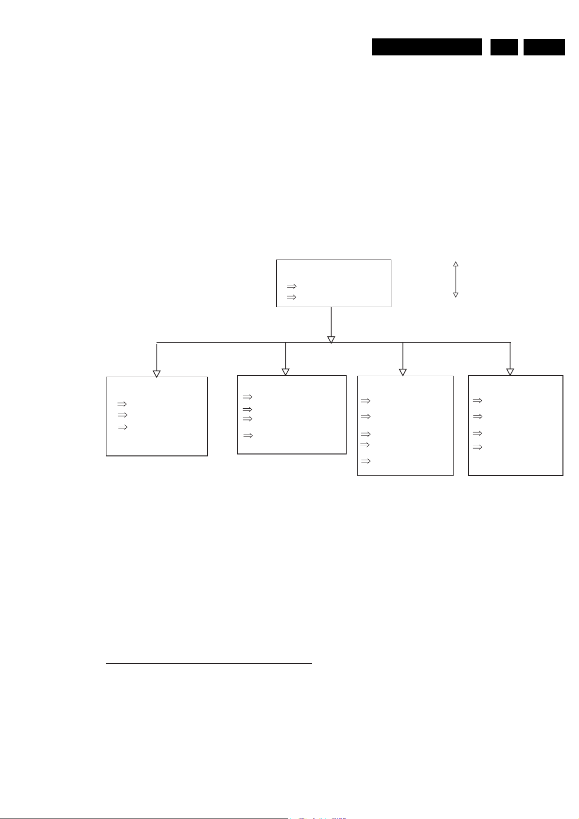
4 Dismantling instructions and exploded view
4.1 Dismantling instructions DVP320
See exploded view for item numbers
Front ASSY 200
Remove screws (Item 230)
Remove flex connections to Mpeg
DVP320
Demounting
4.Dismantling instructions and exploded view EN 21
Mounting
Display board 1003
Remove 4 screws item 212
Demount board
Remove flex to Front board
Loader module 1001
*
Remove screws item 214
Demount the module
Soldering the ESD protection point
at the loader module
Remove flex connections to
Loader board
MPEG board 1002
Remove top shield (item 219,
refer to service hint for details)
Remove screws item 223 &
225
Remove screws item 227
Remove flex connections to
Mpeg board
Demount board
PSU board 1005
Remove flex connections to
PSU board
Remove screws item 229
(PSU board to frame)
Release 3 snaps of locking
Demount board
*
Note: Because DVD Loaders are very sensitive to ESD. During replace, must obey the procedure.
Refer to service hints for details
Page 22
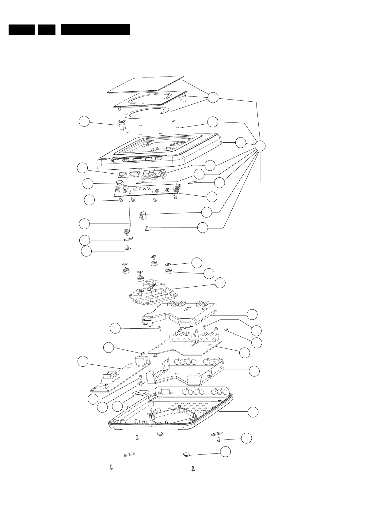
4. Dismantling instructions and exploded viewEN 22
DVP320
4.2 Explode View
0040
1006
0030
0207
0209
0210
0211
0212
(4X)
0070
0214
0050
0060
(4X)
0090
0020
1003
0221
0080
(4X)
1001
0010
0200
To item 0030
*Remark:
Item 0200 includes 9 parts.
They are 0010, 0020, 0030,
0040, 0050, 0060, 0070, 0080,
0090
1005
0215
0216
0229
0223
5002
(2X)
0219
0225
0227
(4X)
1002
0217
0213
(4X)
0230
(4X)
0020
*Remark: The 4 rubber feet are included in item 0213
It is available as spare part by 3141 013 20521
Page 23
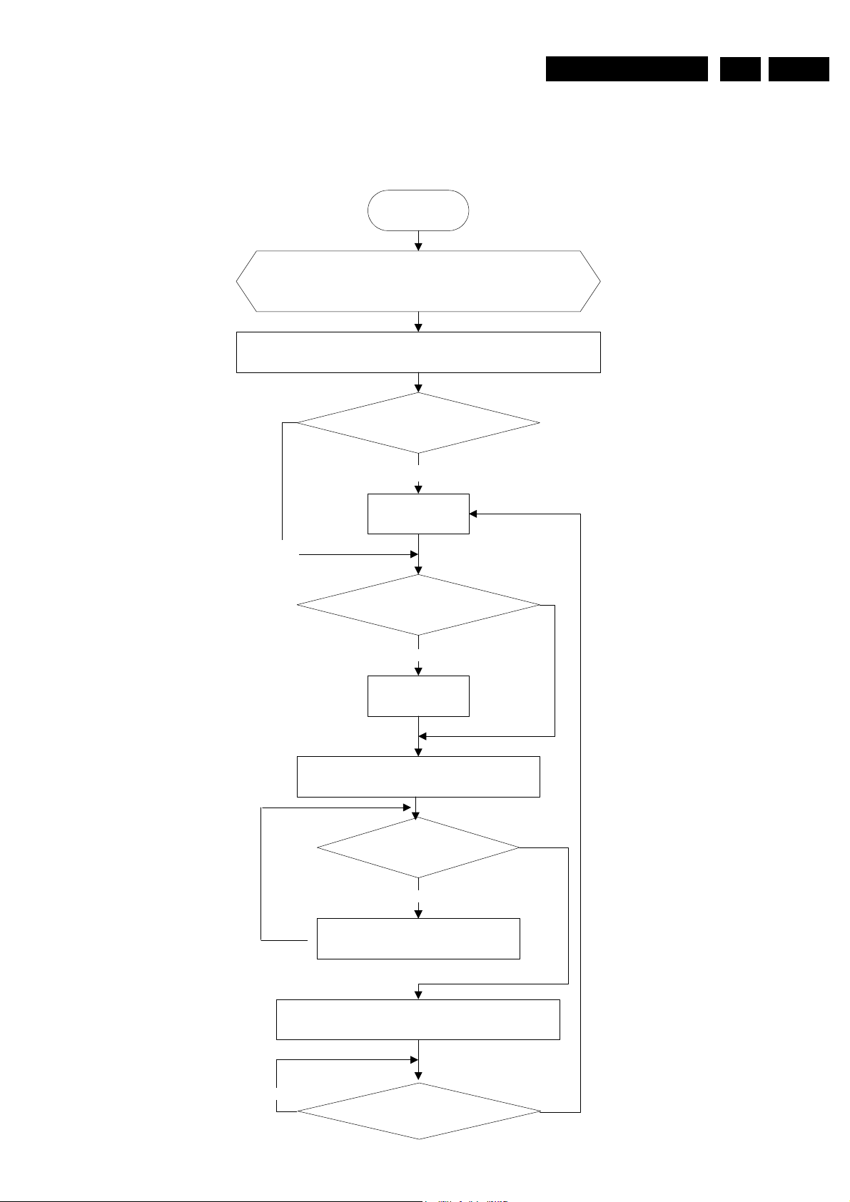
DVP320
5.Diagnostic Software descriptions and troubleshooting EN 23
5. Diagnostic Software, Trouble Shooting and Test Instructions
Diagnostic Software reserved. It will be prepared later.
5.1 System working procedure for MediaTeK DVD-Player (MT1379 + MT1366)
Power on
1. Initialize related registers (servo, DSP, RISC)
2. Move code related with RISC to SDRAM
3. Reset RISC
Display LOGO
Does tray close?
N
close tray
Yes
Does SLED move to inside?
No
Move to inside
1. Judge if a disc has loaded
2. Jump to related subroutine acc. to the type
of disc
No
Do it receive a command
to open the tray?
NoNo
No
1. Key scan or receive RC singnal
2. Run the other subroutine
YES
YES
YES
1. Stop play disc, then open tray completely
2. Display picture and information of opening
No
Does it receive the command to close
tray?
Page 24
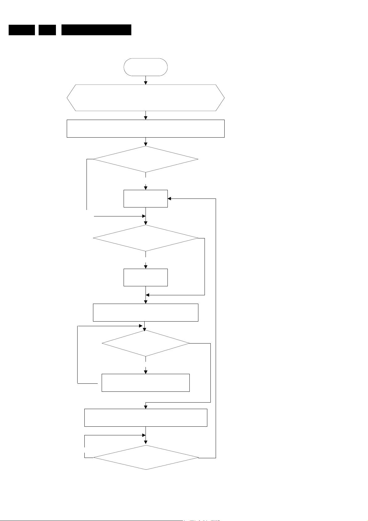
5. Diagnostic Software descriptions and troubleshootingEN 24
DVP320
5.1 System working procedure for MediaTeK DVD-Player (MT1379 + MT1366)
Power on
1. Initialize related registers (servo, DSP, RISC)
2. Move code related with RISC to SDRAM
3. Reset RISC
Display LOGO
Does tray close?
N
close tray
Yes
Does SLED move to inside?
No
Move to inside
1. Judge if a disc has loaded
2. Jump to related subroutine acc. to the type
of disc
No
Do it receive a command
to open the tray?
NoNo
No
1. Key scan or receive RC singnal
2. Run the other subroutine
YES
YES
YES
1. Stop play disc, then open tray completely
2. Display picture and information of opening
No
Does it receive the command to close
tray?
Page 25
5.2 Maintenance Flow chart
Start
DVP320
5.Diagnostic Software descriptions and troubleshooting EN 25
Confirm if AC is compatible with
the DVD-Player require
Yes
Power on
Voltages
in all pins of item 1601 are
normal?
Yes
Are
DV33 and V25
normal?
Yes
Display LOGO?
No
No
No
No
Replace extainal
PSU or a
transform need
1. Check Cable
2. Replace PSU if Mono PWB is not short, otherwise find out
where short first
Check regulator LD1117 (item7601) and diode 1N4002 (item6604)
and peripheral circuit
Is
Main Clock
normal?
N
1. Check oscillation circiut.
Yes
A
Y
Is
reset signal
normal?
Y
Is
signal on FLASHl
normal?
Y
Is
signal on SDRAM
normal?
Y
Is input
signal of TV encoder
normal?
Y
Is output
signal of TV encoder
normal?
Y
Check the circuit of video
filter, amplifying and cables
with TV
N
1. Check reset circiut.
N
Check peripheral circiut of FLASH
N
Check peripheral circiut of SDRAM
Check peripheral circiut of TV
N
Encoder
Check peripheral circiut of TV
N
Encoder
Page 26
5. Diagnostic Software descriptions and troubleshootingEN 26
A
DVP320
If will the tray
close automatically when
it is open
YES
Sledge move to
inside automatically when
it is in outside?
Signal
N N
N N
TROUT and TRIN is
correct?
Y
Signal
TRCLOSE & TROPEN
correct?
Y
Signal
LOAD+ & LOAD-
correct?
Y
Check the circuit to
connect LOADER
Signal
STBY on driver IC is high
level?
Check the position-switch
Check the circuit between
N
N
MT1336 and driver IC
(item7603)
(item7603) and peripheral
Check the circuit related
with STBY
in LOADER
Check Motor driver IC
Y
NO disc on tray
Have
the Loader action
to find disc
Y
Y
Signal
FMSO is more than
1.4V?
Yes
Signal
SL+ & SL-
correct?
Y
Check the copper trace or
cable connect to LOAD ER
N N
Have
FOSO on driver IC
any signal ?
Y
Signal
F+ & Fcorrect?
No
N
N
Check the circuit related
with FMSO
Check Motor Driver
1. Check the signal from
MT1379 to Motor Drive r ;
2. Maybe MT1379 is n ot
work
Check the peripheral
circuit of Motor driv er
Y
Check the cable and
circuit between Loader and
Motor driver (BA5954)
B
Page 27
DVP320
5.Diagnostic Software descriptions and troubleshooting EN 27
B
When read disc,
Laser ON OK?
Y
Load a disc?
Y
Focus On ok?
Check the peripheral
Signal
N
N
Laser off
N
LDO1 and LDO2 is
normal?
Y
Voltage of
TP22 &TP24
OK?
Any signal
on pins A B C D E F
of MT1366
Y
Signal FEO
(pin18 of MT1336)
correct?
N
N
Y
N
N
circuit of MT1366
Check the peripheral
circuit of two transistor
(item 7620 & 7621)
Check the peripheral
circuit of two transistor
(item 7620 & 7621)
Check the circuit to
connect LOADER
OPU maybe damaged
Check the circuit between
Loader and MT1336
Check the peripheral
circuit of MT1336
Y
Disc ID correct?
Y
Spindle on OK? N
Y
Check the circuit from
Pin18 of MT1336 to Pin205
N
Pin19 of MT1336 to Pin206
of MT1379
Signal of
Pin 19 (RFL) of MT1336
normal?
Y
Check the circuit from
of MT1379
DMSO
(pin18 of MT1379)
normal?
Y
Signal
SP+ & SP-
correct?
N
N
N
Check the peripheral
circuit of MT1336 and
itself.
Check MT1379 and its
peripheral circuit.
Check BA5945 (motor
driver) and its peripheral
circuit
C
Check the connection
between spindle driver and
BA5945
Y
Page 28
5. Diagnostic Software descriptions and troubleshootingEN 28
C
DVP320
Track on OK? N
Y
Disk is READY? Check RF SignalN
Y
Signal TEO
(pin21 of MT1336)
normal?
Y
Signa TRSO
(pin13 of MT1379)
normal?
Y
Signa l
T+ & T-
normal?
Y
Check the connection
between OPU and BA5945
N
N
N
Check MT1336 and its
peripheral circuit.
Check the TRSO connection
between MT1379 (pin13) and
MT1336 (pin26)
Check MT1336 and its
peripheral circuit.
Audio signal normal? N
Y
IR,VFD display
and Key fuction
ok?
Y
Audio DAC receive
correct data?
Y
Output signal are
correct?
Y
Check the circuit of
filter, Amplify, and mute
etc.
N N
check Remote Contriol
check KEY matrix
Check connection of VFD
IR, PT6312
communicate with
MT1379 OK?
Y
N
N
Check connection between
MT1379 and Audio DAC
Check Audio DAC and i t s
periperal circuit
Check connection between
MT1379 and PT6312 and its
periperal circuit
END
Page 29
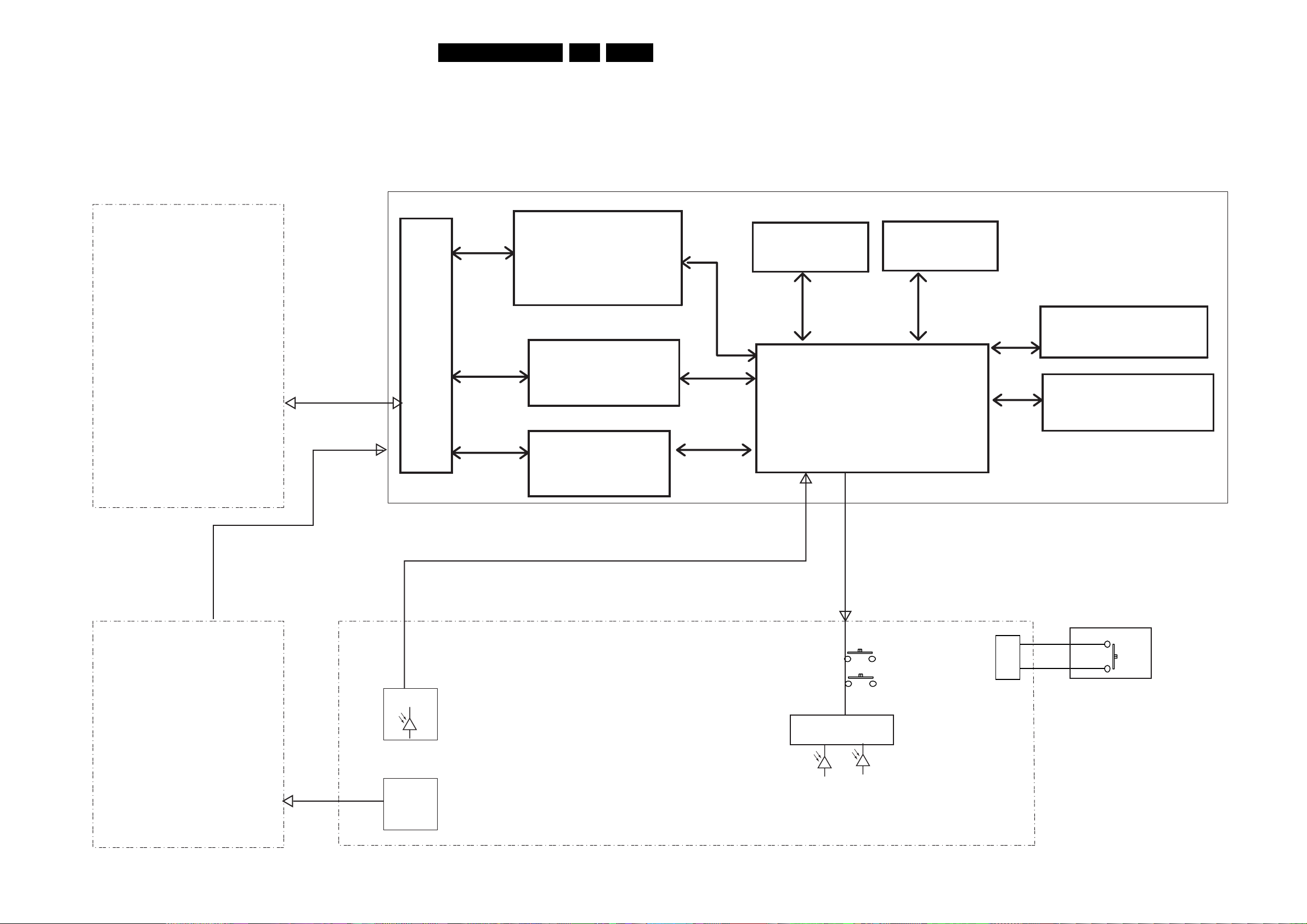
Block and wiring diagrams DVP320
6 Block and wring diagram
6.1 BLock diagram DVP320
6.
EN 29
LOADER MODULE
KHM-280AHA
1609
7602
RF AMPLFIER
7603
MOTOR DRIVER
7604
MOTOR DRIVER
MT1336
BA5954
BA6208
7609
8 Mbit FLASH
7606
MTK MT1379BE
SERVO AND MPEG DECODER
7611
64 Mbit SDRAM
MPEG BOARD
1605/1603/1606
ANALOG VIDEO OUTPUT
CVBS/Y/C/Y/Pb/Pr
7615
2-CH AUDIO DAC
AKM4382
POWER SUPPLY
FRONT BOARD
RECEIVER
POWER
BUTTON
Door Locking Switch
1405
1006
Transistors
Page 30
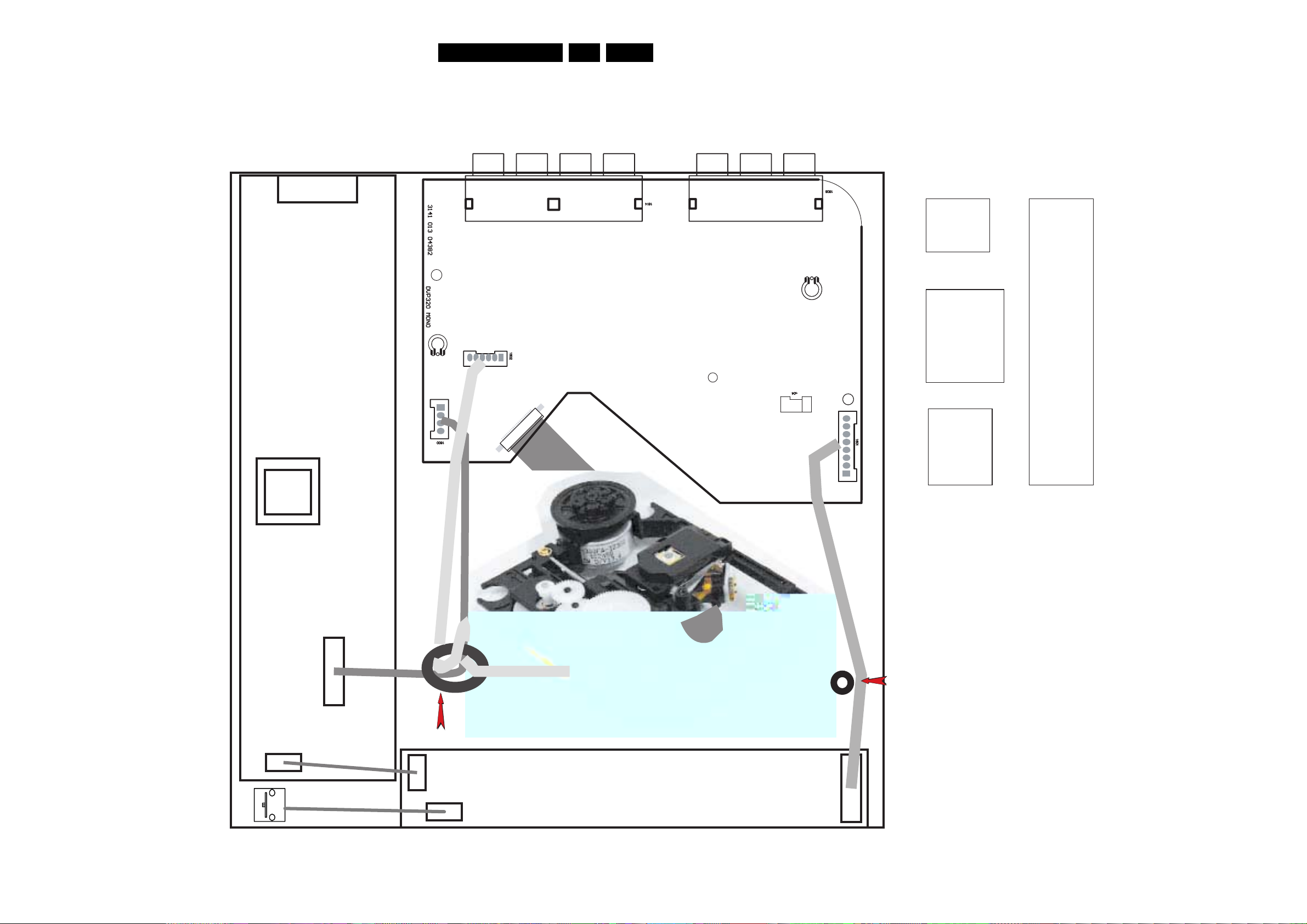
6 Block and wiring diagram
6.2 Wiring diagram DVP320
DVP320
6.Block and wiring diagrams
EN 30
PSU
1600
1600
1 VCC (5V)
2 GND
3 -12V
4 GND
1601
MPEG Board
1602
1
1
26
1
1609
24
25
8001 314101021882
1604
1601
1
1 STBYLED
2 OPEN/CLOSE
3 RC
4 GND
5 VCC
6 STOP
7 PLAY
8 LED
1602
1 SP+
2 SP3 SL4 SL+
5 GND
6 LIMIT
1609
1 F2 F+
3 T+
4 T5 C
6 D
7 CD/DVD
8 RF
9 A
10 B
11 F
12 GND-PD
13 Vc
14 VCC
15 E
16 NC
17 VR-CD
18 VR-DVD
19 LD-CD
20 MD
21 HFM
22 NC
23 LD-DVD
24 GND-LD
25 GND
26 GND
8005
314101021932
CN201
CN202
12
8401
314101021941
8004
314101021951
Door Locking Switch
8002 314101021911
4
8003
314101021921
1
Screw Post
Note:
The cable 8002 will be damaged by the
screw if to lay it on the screw post during
assembling bottom and top cabinet.
The ferrite ring is only for /17 stroke vision
1406
Front Board
1409
1405
Page 31
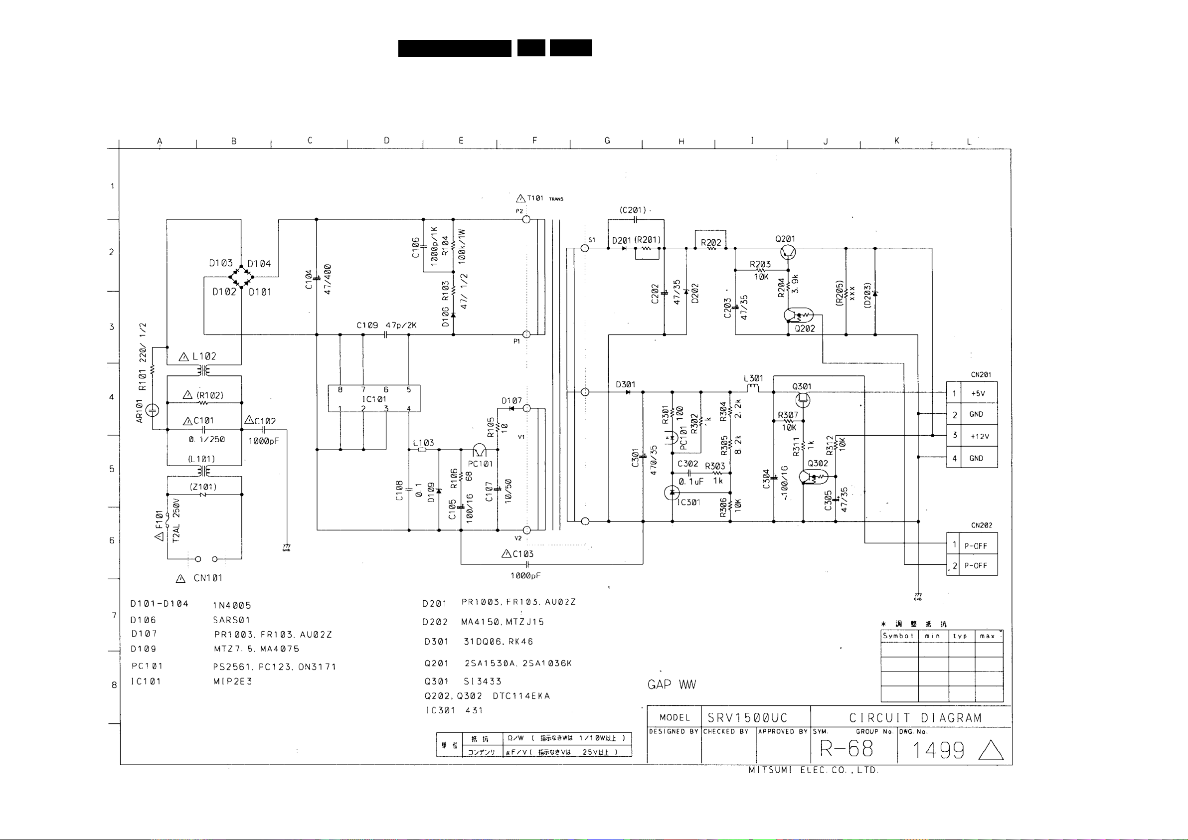
Electrical Diagrams and Print-layouts
Electrical Diagrams PSU DVP320 (MITSUMI)
DVP320
7.
EN 31
AR101 A4
C101 B4
C102 B4
C104 C2
C105 E5
C106 E2
C107 F5
C108 D5
C109 D3
C113 F6
C202 H3
C203 I3
C301 H5
C302 H5
C304 I5
C305 J5
CN101 B6
CN201 L4
CN202 L6
D101 B2
D102 B2
D103 B2
D104 B2
D106 E3
D107 F4
D109 E5
D201 G2
D202 H2
D301 G4
F101 A6
IC101 D4
IC301 H5
L102 B4
L103 E5
L301 I4
PC101 E5,H4
Q201 I2
Q202 J3
Q301 J4
Q302 J5
R101 A4
R103 E2
R104 E2
R105 F4
R106 E5
R203 I2
R204 I2
R301 H4
R302 H4
R303 I5
R304 I4
R305 I5
R306 I5
R307 I4
R311 J5
R312 J5
T101 F
Page 32
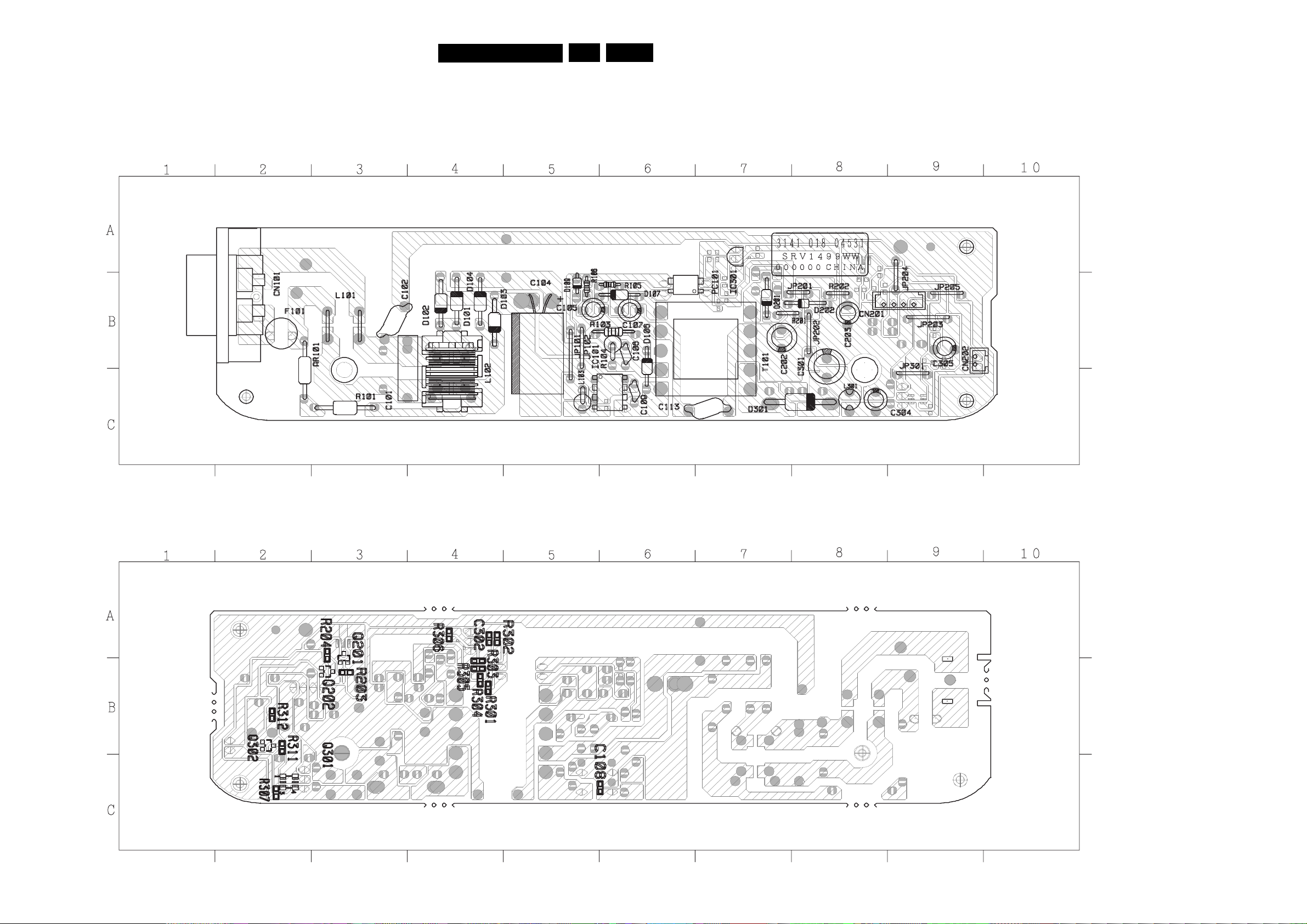
Layout PSU MITSUMI DVP320
Components Side
DVP320
7.Electrical Diagrams and Print-layouts
EN 32
AR101 B2
C101 B3
C102 B2
C104 B5
C105 B5
C106 B6
C107 B6
C109 C6
C113 C7
C202 B7
C203 B8
C301 B8
C304 C8
C305 B9
CN101 B2
CN201 B9
CN202 B9
D101 B4
D102 B4
D103 B4
D104 B4
D106 B6
D107 B6
D109 B5
D201 B7
D202 B8
D301 C8
F101 B2
IC101 C6
IC301 A7
L102 B4
L103 C5
L301 C8
PC101 B6
R101 C3
R103 B6
R104 B6
R105 B6
R106 B5
T101 B6
Copper Side
C108 C6
C302 A4
R203 B3
R204 A3
R301 B4
R302 A4
R303 B4
R304 B4
R305 B4
R306 A4
R307 C2
R311 B2
R312 B2
Q201 A3
Q202 B3
Q301 C2
Q302 B2
Page 33
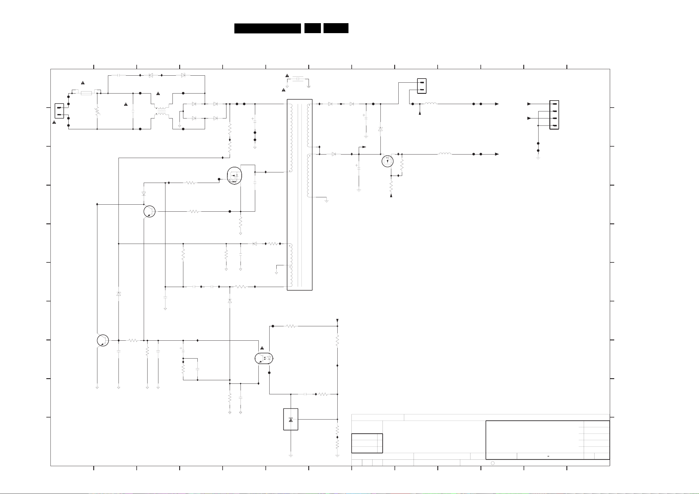
Electrical Diagrams and Print-layouts
DVP320
Electrical Diagrams PSU DVP320 (EPM 3122 429 00201)
7.
EN 33
A
B
C
D
F101
2
1
0100
AC-M09PB42
HT 2.50A 250V
F102
F103
F104
1110
3109
I120
V
2116
2322595
33n
2110
BC847B
I101
BZX79-C15
F105
100n
F106
6126
7125
6116
BAS316
I102
5115
UF1717V
4
1
3
2
I115
6117
BZX79-C15
F108
1N4006
1N4006
F107
3123
47R
6112
3143
100R
61116110
1N4006
6113
1N4006
I110
F113
F114
F109 F110
1M5
3130
I109
1M5
3131
STP3NK60ZFP
3127
7126
1R8
2117
2127
F111
F112
22U
I106
220p
654321
2190
1n
5199
PSE20T
56
10
1
7
6210
I210
PG102R
I220
6221
8
SB360
7
I211
6211
PG102R
I221
F212 F213
100u
2210
6222
Vreg1
7221
1m
2221
SI2302DS
BZX79-C7V5
I222
I223
1K
3221
SW12V
3222
33K
0202
EH-B
2
1
SW12V
5210
10u
5224
10u
F210
F220
F211
F221
+5V
+12V
+5V
+12V
F201
F202
1312111098
0201
EH-B
1
2
3
4
A
B
C
D
E
G
H
6131
BAV21
180K
2131
3141
100R
BAV21
TCET1102
2K2
2139
22n
7190
100n
2142
560p
3132
I125
6141
3138
22K
3125
I124
2136
3136
I119
15K
2144
560p
4u7
I116
2138
22n
F
6133
7137
BC847B
2137
I122
UDZ-30V
220n
6K8
3133
3134
100K
2135
2111
220n
470p
I
J
1
I126
I117
3110
2
470R
3
4
Vreg1
3297
3292
3K3
3291
3290
7
F291
3295
22R
1
2
2292
100n
7290
TL431CZ
3
I291
F290
65432 1312111098
I290
I292
5K1
3K9
1K0
SETNAMECHN
CLASS_NO
DVD GAP
2003-09-30
2003-10-24
M.Charpentier 130
WR
SUPERS.NAME
2003-06-04
DATECHECK
C
3122 427 23710
KONINKLIJKE PHILIPS ELECTRONICS N.V. 2000
E
F
G
H
I
2003-10-14
2003-09-26
2003-08-26
2003-06-26
2003-06-04
11
J
A3
I129
I128
Page 34
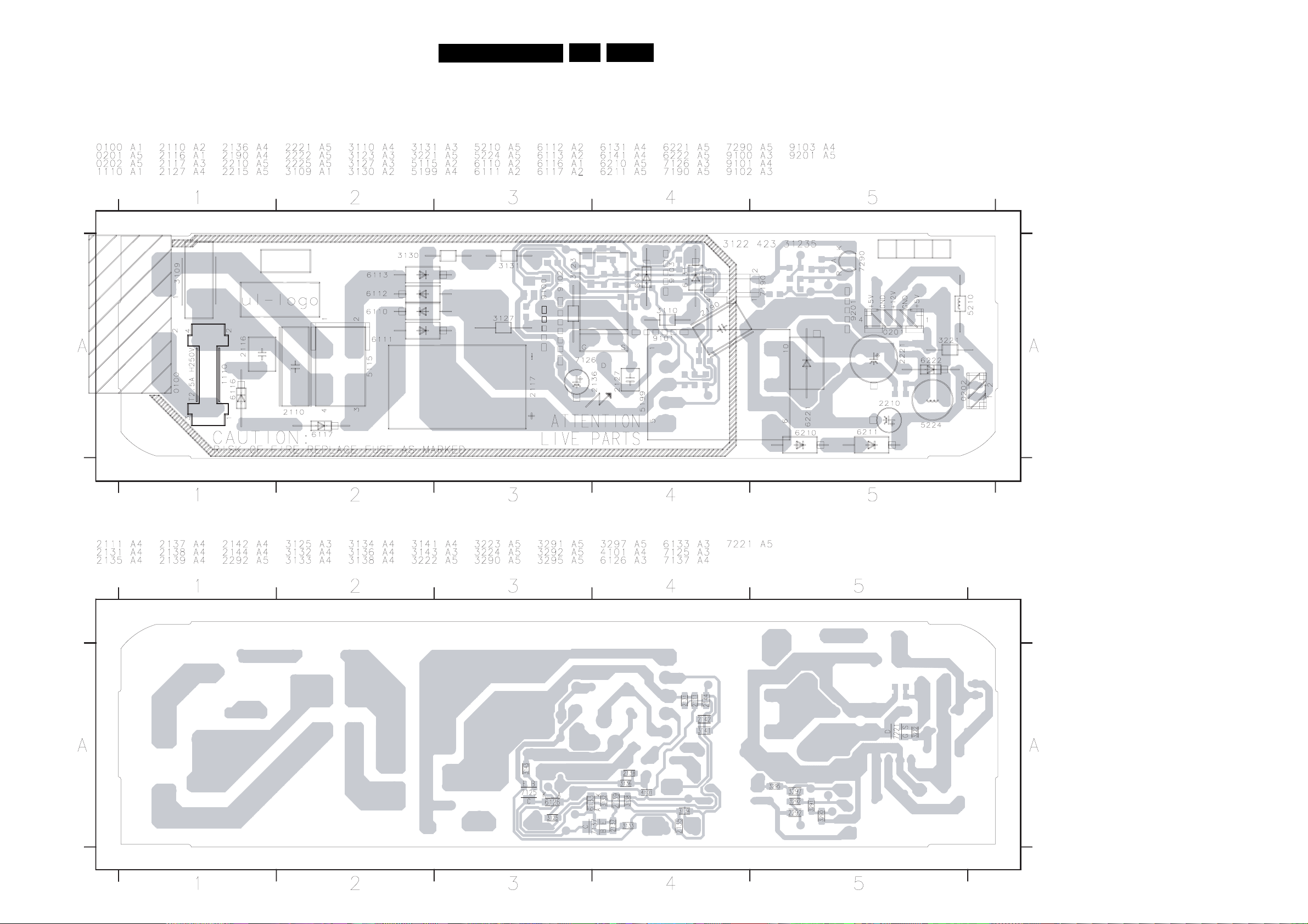
Layout PSU EPM DVP320
Components Side
DVP320
7.Electrical Diagrams and Print-layouts
EN 34
Copper Side
Page 35
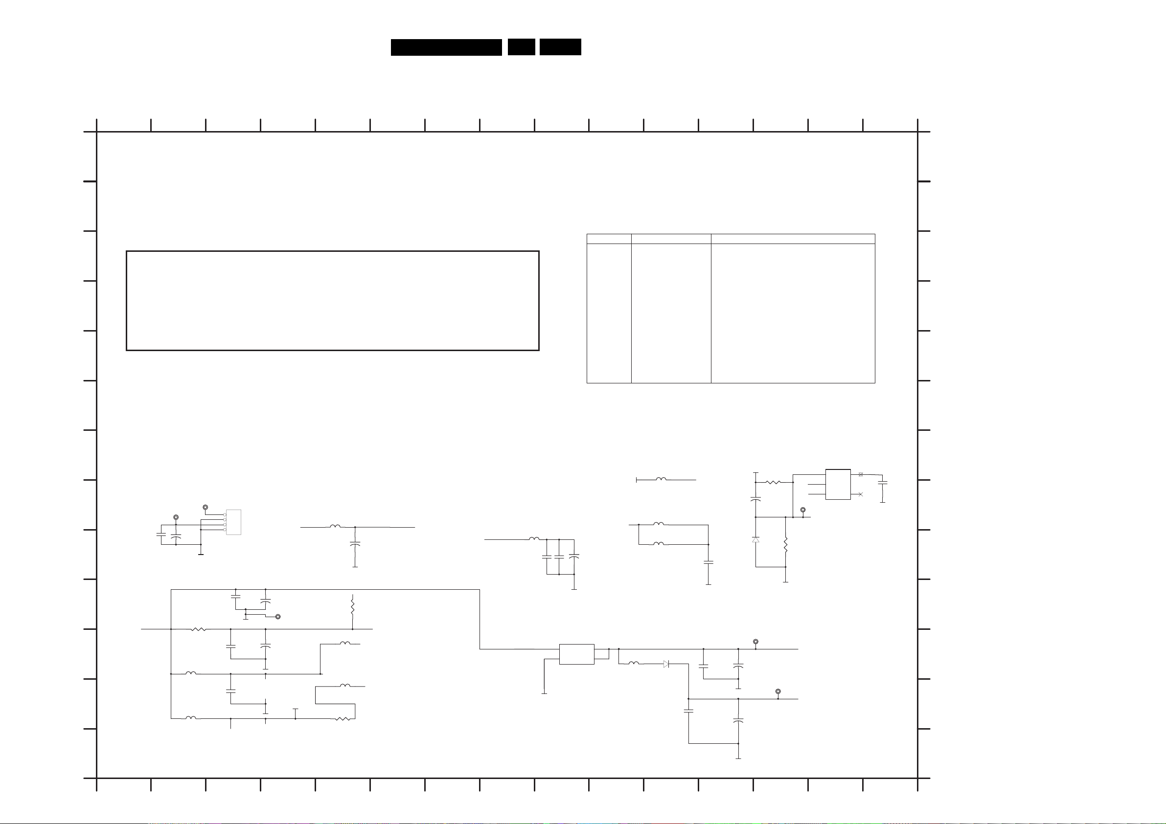
Electrical Diagrams and Print-layouts
Electrical Diagrams MPEG DVP320
MPEG Board: INDEX
DVP320
7.
EN 35
123456789101112131415
1600 H3
2601 J4
A
A
2602 J3
2603 K3
2606 K12
2607 L3
B
B
2608 L11
2682 I9
2683 I9
MT 13 79 E (L QFP2 1 6 ) DVD Dem o B o a r d fo r A c t i m a PU H
C
D
E
1 INDEX & POWER, RESET
2 RF - MT1336E/MT1376
3 SERVO & MPEG - MT1379E
4 MEMORY - SDRAM, FLASH/EEPROM
5 VIDEO OUT , SPDIF , AUDIO - WM8761
NAME TYPE DEVICE
VCC Digital 5V
V33
DV33 Digital 3.3V MT1369E
AV33
V25
SD33 SDRAMDigital 3.3V
VCC5330
+12V
8756D
+5V
+5V8756A Audio 5V Audio DAC
Servo 3.3V
Digital 2.5V
V Audio filter
Audio 12
io 5V
Aud
SUPPLY
MT1336EServo 5VRVCC
PICKUP HEADERRF 5VAVCC
Flash, VideoDACDigital 3.3V
MT1369E
MT1369E
VIDEO+5VV VIDEO 5V
AudioAudio 5V
io DAC
Aud
2684 I9
2717 I12
C
2719 I2
2781 K4
2782 H12
2783 K12
D
2785 L12
2797 I5
2799 I2
2815 H15
E
3611 I13
3612 L5
3618 J3
3619 J5
F
F
3817 H13
5602 K10
5603 K2
5604 L2
G
7650
URST
1
2
3 4
P302
NC
5
DV33
GND
09
TP
URST
GND
2815
0.1uF
GND
DV3 3
3817
OPEN
+
2782
10uF/25v A
6605
3611
1N4148
10k
GND
03
TP
DV33
+
2783
0uF/10v A
22
TP05
V25
+
2785
uF/10v A
220
DV
5602
FB
33
5618
10UH,DIP
5614 FB
5627 FB
6604
1N4002
VCC
4340 ->power supply
CS
wer supply
po
MUTE power supply
5623 150R
+12V +12VOP
For 3.3V
2601
100uF/16v A
RFVCC
06
RVCCIN
56
FB,0805
5605
FB,0
3612
0R,OPEN
2781
100uF/16v A
AVCC
AVCC
2797
+
100UF/16v A
GND
DV33
3619
0R
DV33
1336 power supply
DV33
805
LDO_AVCC
loader power supply
LPF power supply
1336 power supply
5610
FB
GND
DACV33ADV33
2684
0.1uF
3
1
2682
0.1uF
01LD1117
76
IN
ADJ/GND
GND
to 1379
+
2683
uF/16v A
47
2
OUT
4
OUT
H
19
27
0.1uF
I
J
VCC
K
L
TP01
+12
2799
+
22UF/25v
TP02
VCC
V
GND
3618
,OPEN
0R
3
560
FB,0805,OPEN
5604
FB,0805
1600
1
2
3
4
HEADER4
GND
2603
0.1uF
260
0.1uF
2602
0.1uF
7
+
TP99 GND
+
GND
GND
SD33
+5VV
2608
0.1uF
GND
2717
0.1uF
2606
0.1uF
G
H
I
J
K
L
5605 L5
5606 K5
5610 I8
5614 H11
5618 H11
5623 H5
5627 I11
6604 K11
6605 I12
7601 K9
7650 G14
TP01 H2
TP02 H3
TP03 K13
TP05 L13
TP09 H14
TP99 J4
M
GND
M
123456789101112131415
Page 36
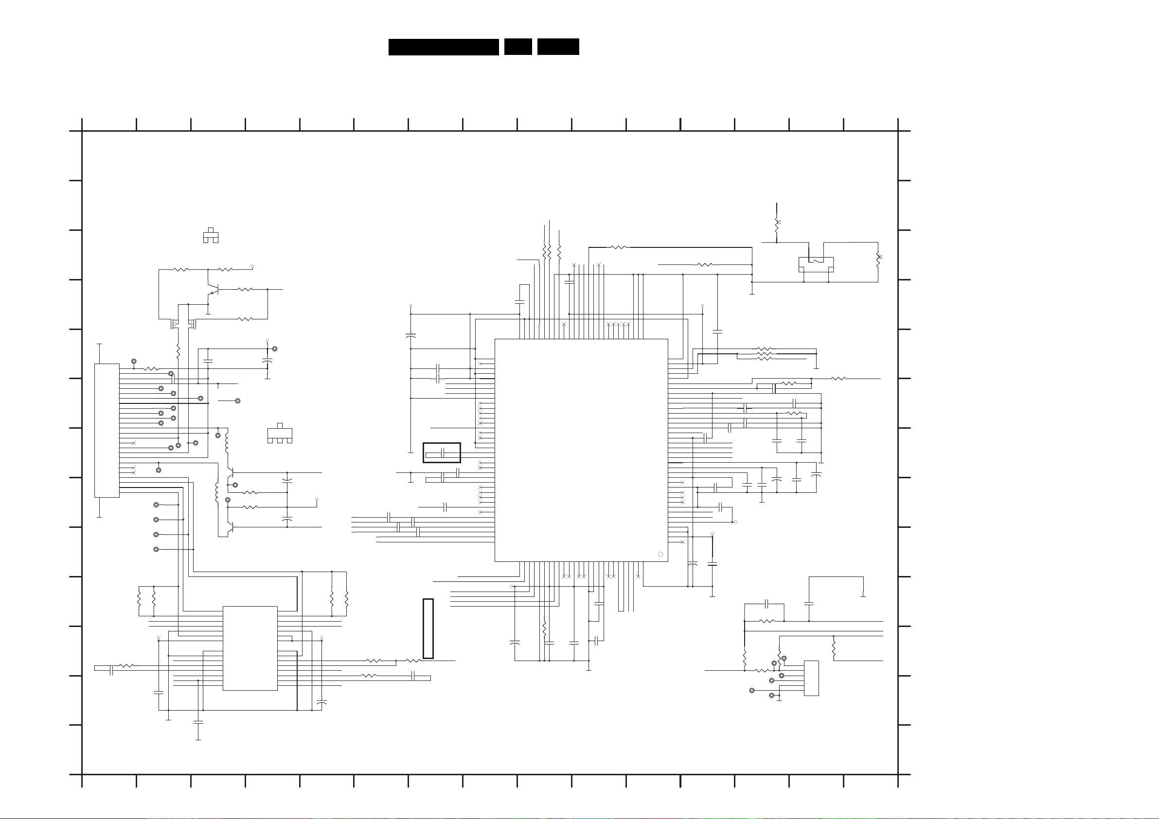
DVP320
7.Electrical Diagrams and Print-layouts
EN 36
Electrical Diagrams MPEG DVP320
MPEG Board: RF Part
123456789101112131415
A
B
2
C
1
3
E
B
TP61
TP63
TP65
TP71
FMSO
TRSO
V1P4
STBY
2N3904
GND
7631
2SK3018
TP62
TP70
5609
10uH,DIP
GND
2775
0.1u
37
TP69
15
16
17
18
19
20
21
29
22
23
24
25
26
27
28
34 10K
7632
BC847B
2771
0.1u
V20
TP12
CC
AV
3735 10K
3736 100K
Very Important to reduce Noise
TP77
5607
10uH,DIP
7620
2SB1132
TP11
3629 4.7
3630 4.7
2SB1132
7621
7603
OTK+
V
OTK-
V
VOLD+
VOLD-
PGND
VNFTK
PVCC2
PGND
PREGND
VINLD
2
CTK
CTK1
VINTK
BIAS
STBY
5954
BA
AVCC
GND
OFC+
V
OFC-
V
VOSL+
VOSL-
PGND
PVCC1
VCC
PGND
VNFFC
VOSL
NSL-
VI
VINSL+
CF2
CF1
VINFC
GND
IOA
TP
+
2786
220u
C
B
2SB1132
79
EC
LDO2
2625
+
47u
LDO_AVCC
+
2634
47u
LDO1
3633
14
13
12
11
10
9
8
30
7
6
5
4
3
2
1
1,0805
VC
C
33 100K
37
D
7630
2SK3018
GND
E
28
F
LD(DVD)
G
27
H
GND
1609
GND
DVDV R
CDVR
LD(CD)
FCS(+)
FCS(-)
TRK(+)
TRK(-)
GND
FP
RF
F
Vc
Vcc
A
G
H
GND
C
D
E
B
GND
N/C
PD
GND
N/C
N/C
C-26P-TOP
TP78
1
RFO
2
3
4
5
6
7
8
9
10
11
12
13
14
15
16
17
18
19
20
21
22
23
24
25
26
1K
3738
F
V20
A
G
H
C
D
E
B
MDI1
TP72
TP75
TP74
TP73
TP68
3737
100
TP66
2772 0.1u
TP60
TP64
TP67
TP76
I
USE 0805 PART
J
3631
1,0805
SL+
SL-
VC
3632
1,0805
C
K
3638 20k
2643 150p
2774
.1u
L
0
GND
M
123456789101112131415
1602 K14
1609 E1
1620 C14
2610 D10
2611 D9
2612 E12
2614 E7
A
2615 F7
2616 F13
2617 F14
2618 F13
VCC
SDEN
SDATA
SCLK
TRCLOSE
53
IOB
SVDD
114
26
0.1uF
ENDM
IOA
51
52
OA
I
I
TP
116
115
47
GND
STBY
LIMIT
TROUT
48
49
50
IO7
IO8
IO9
WGAND
SGND
TNI
119
118
117
26
0.1uF
3621 10k
OPEN/CLOSE2
44
45
43
46
47
1
IO
IO2
IO3
IO4
IO5
IO6
1
MDI
MDI2
AGC3
AGC2
WAVD D
AGC1
124
123
122
121
120
MDI1
2642
0.015uF
45
20 10k
ENDM
7602
MT1336E
39
40
42
41
IO0
GND
UDGATE
HDGATE
VFO13
VDD
AGNDX
AGNDX
AGNDX
DPFO
DPFN
GNDP
HTR
TRLP
TRLPA
CRTPLP
CRTP
HRFRP
LRFRP
DEFECT
VDDP
TEO
CSO
LVL
FEO
V20
VREFO
V2REFO
AVDDT
TM4
AGNDT
TM3
TM
TM
AGNDO
RFON
RFOP
AVDDO
AGNDX
AGNDX
WVDD
WOBSO
WGND
RFSUBO
LDO2
LDO1
128
127
126
125
LDO2
LDO1
36
2612
0.1uF
P36
P35
HTRC
USE 1376
3643
330k
2618 OPEN
2619 82
RVCCIN
GND
3622 OPEN
3623 OPEN
3624 R
C19 = 100P
2631
0.1uF
RFVCC
38
37
36
35
4
3
33
32
31
30
C
29
28
27
26
25
RFRP
24
23
22
21
20
19
18
17
16
15
14
13
12
11
10
2
9
1
8
7
6
5
4
3
2
1
47uF/16v A
BDO
2621
0.1uF
2630 0.1uF
RFON
OP
RF
RVCCIN
2788
+
2620 390p
TEO
CSO
RFL
FEO
V20
V1P4
V2P8
2635 0.1uF
2641
0.1uF
GND
SP-
3802
65
AGNDF
66
VCON
67
AVDDF
68
AGNDX
9
6
AVDDM
70
COSPHI
71
HALLCOS
72
REFC
73
AGNDM
74
HALLSIN
75
REFSIN
76
SINPHI
77
SW0
78
SW2
79
SW1
80
MOP
81
MON
82
AGNDX
83
AGNDX
84
CEON
85
CEOP
86
RFGCI
87
RFGCU
88
RFFGC
89
OSP
90
OSN
91
CDD
92
CDC
93
CDB
94
CDA
95
DVDRFIN
96
DVDRFIP
97
DVD D
98
DVD C
99
DVD B
100
DVD A
101
MA
102
MB
RVCCIN
47uF/16v A
2611
0.1uF
63
64
AVDDP
OS
MC
104
103
+
89
27
USE 1376 R25 = 15K OHM
AGNDX
MD
62
AGNDP
SA
105
RVCCIN
+
2787
6v A
100uF/1
F
2614 0.1u
615 0.1uF
2
ADIN
OP-
OP+
SW1
1376 C25 = 500P
USE
2624 470P
GND
26 0.1uF
26
2627 0.1uF
GND
2636 1U
40 1uF
2639 1
2637 1uF
3636
20k
2644
150
RFO
uF
C
D
F
H
G
E
DMSO
p
2638
C
1uF
D
A
B
USE 0805 PART
3634
1,0805
SP-
SP+
C
V1P4
3639 20K
O
FOS
+
2648
47U
3635
10K
26
A
B
33R
URST
OUT2
PWM
60
61
DPDMUTE
MT1336E
SB
107
106
RST
AGND
59
108
3637 15K
3804
33R
380333R
2610 0.1uF
8
54
55
56
57
5
SCLK
VDDS
SDEN
GNDS
SDATA
XCK16M
SMD LQFP-128
CDFON
CDFOP
SD
SC
AVDD
IR
09
113
112
111
110
1
46
26
0.1uF
376 R15 R16 NOT STUFF
USE 1
3625 OPEN
2616 OPEN
3626 OPEN
P
2632
0.1uF
10uF/16v A
GND
2650
/OPEN C Ver.
C
3640
750k
TP81
45 1
36
TP82
TP83
TP84
MIT
LI
TP85
GND
3601
OPEN
OPEN/CLOSE2 OPEN/CLOSE1
1
2
1620
3
4
DETECT SWITCH
1
2
3
4
HSYNC#
GND
627 27k
3
USE 1376 R17 R18 C17 C18 C23 NOT STUFF
2617 0.015uF
2623
2622
0.033uF
OPEN
GND
TP80
SP+
SL-
SL+
1
2
3
4
5
6
2628
0.1uF
1602
HE
1
2
3
4
5
6
ADER6
+
2629
10uF/16v A
2649
0.1uF
3642
750k
33
26
+
30k
3
3644
GND
SW1
ADIN
OP-
OP
V1P4
+
3600
10
B
C
k
D
E
F
G
H
I
J
K
L
2619 F13
2620 G12
2621 G12
2622 G13
2623 G14
2624 G7
2625 H4
2626 H7
2627 H7
2628 H14
2629 G14
2630 H12
2631 H13
2632 H13
2633 G13
2634 H4
2635 H12
2636 H7
2637 I7
2638 H6
2639 I7
2640 I6
2641 I12
2642 J10
2643 L1
2644 L7
2645 K10
2646 K9
2647 K9
2648 L5
2649 J14
2650 J13
2771 E3
2772 F2
2774 L2
2775 L3
2786 E4
2787 E6
2788 I12
2789 K8
3600 C15
3601 C13
3620 C12
3621 C10
3622 E13
3623 E13
3624 E13
M
3625 F13
3626 F13
3627 F14
3630 H3
3631 J1
3632 J2
3633 J5
3634 J5
3635 K6
3636 K6
3637 J9
3638 K1
3639 L6
3640 K13
3642 K14
3643 K13
3644 K13
3645 L13
3733 C2
3734 C3
3735 D3
3736 D3
3737 E2
3738 E2
3802 C9
3803 C9
3804 C9
5607 G3
5609 H3
7602 E11
7603 L4
7620 H3
7621 H3
7630 E2
7631 E3
7632 D3
TP11 H3
TP12 H3
TP60 F2
TP61 F2
TP62 F3
TP63 F2
TP64 F2
TP65 F2
TP66 F2
TP67 G2
TP68 G2
TP69 G3
TP70 G3
TP71 G2
TP72 H2
TP73 I2
TP74 I2
TP75 H2
TP76 G2
TP77 F3
TP78 E2
TP79 E4
TP80 K14
TP81 K13
TP82 K13
TP83 L13
TP84 L13
TP85 L13
3629 H3
Page 37
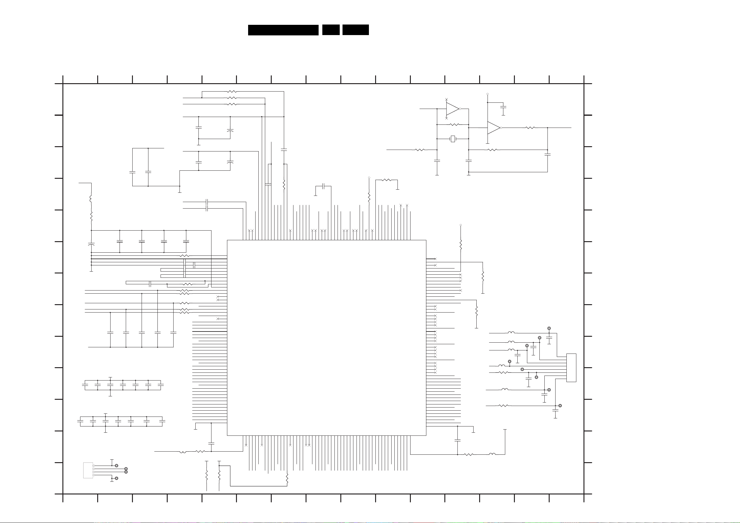
Electrical Diagrams and Print-layouts
Electrical Diagrams MPEG DVP320
DVP320
7.
EN 37
MPEG Board: SERVO & Mpeg Part
123456789101112131415
2668
1uF
GND
C
2681
5626
FB
RFRPC
HTRC
V1P4
V2P8
RFON
RFOP
2669
GND
2664
2665
0.01uF
36598.2k
26700.01uF
26720.01uF
26730.01uF
366220K
366318K/27k for sony
36640
366510k
366715k
A8
A9
A10
A11
A12
A13
A14
A15
AD7
AD6
AD5
AD4
AD3
AD2
AD1
AD0
A0
A1
A2
A3
A4
A5
A6
A7
A16
A17
A18
A19
A20
GND
3669
4.7
2654 0.1uF
2659 0.1uF
1000pF
1000pF
26710.01uF
3661750k
V25
GND
GND
DV33
V25
DV3 3
3656
1K
SDA
A
B
DV33
C
2662
2661
1uF
DV33
D
5625
FB
3658
4.7
0.1uF
E
+
2791
47uF/16v A
2666
100pF
2667
0.1uF
F
GND
2676100pF
G
FOSO
TRSO
PWMOUT2
DMSO
FMSO
H
2679
2680
330pF/C:560PF
V1P4
2677
0.1uF
2678
0.015uF
330pF/C:560PF
I
V25
2693
2700
0.1uF
0.1uF
DV3 3
GND
GND
2701
0.1uF
2694
0.1uF
2695
0.1uF
2702
0.1uF
J
K
2698
0.1uF
0.1uF
0.1uF
2699
0.1uF
2692
2691
L
1604
M
HEA
DER4
DV3 3
TP86
1
RxD
2
TxD
3
4
TP87
TP89
GND
TP88
2696
0.1uF
2703
0.1uF
1
2697
2
1
0.1uF
2
2704
0.1uF
DV33
123456789101112131415
3648 100k
3649 R
3650 0
+
2655
10U/16V
+
2660
10uF/16v
RFIN
RFIP
216
RFIP
1
IREF
2
PLLVSS
3
LPIOP
4
LPION
5
LPFON
6
P
LPFI
7
LPFIN
8
LPFOP
9
JITFO
10
JITFN
11
PLLVDD3
12
FOO
13
TRO
2687
2.2U/1U
DV3 3
14
15
16
17
18
19
20
21
22
23
24
25
26
27
28
29
30
31
32
33
34
35
36
37
38
39
40
41
42
43
4
45
46
47
48
49
50
51
52
53
54
3657
1K
SCL
4
TROPENP
MOUT1
PW
PWMOUT2
DVDD2
DMO
FMO
DVS S
FG
HIGHA0
HIGHA1
HIGHA2
3
HIGHA
HIGHA4
HIGHA5
DVS S
HIGHA6
HIGHA7
AD7
AD6
AD5
AD4
DVDD3
AD3
AD2
AD1
AD0
IOA0
IOA1
DVDD2
IOA2
IOA3
IOA4
IOA5
IOA6
A7
IO
A16
A17
IOA18
IOA19
IOA20
APLLVSS
WM
APLLVDD355ALE56IOOE#57IO
ZC
RF
DV33
213
215
214
211
212
210
209
RFIN
DTSLVP
ADCVDD3
RF
PWMVREF
RFDTSLVN
PWM2VREF
WR#
IOCS#59DVS S60UP1_261UP1_362UP1_463UP1_564UP1_665DVD D366UP1_767UP3_068UP3_
58
GND
PRD#
PLAY
PCE#
PWR#
2663 1000pF
RFRPC
208
HRFZC
RFRP_AC
STOP
1601 J15
1604 M1
2653 A13
A
B
C
D
2654 B4
2655 B5
2656 C7
2657 C11
2658 C12
2659 C4
2660 C5
2661 C3
2662 C3
2663 D6
2664 D5
2665 D5
2666 E2
2667 E3
2668 E3
2669 E4
DV3 3
147
7605F
13 12
04
74HC
3651
2 1
100k
5701
3653 R 3654 R
3740
1k
XTALO
21
GND
2657
33p
RFRP
2656 0.1uF
2817
680p
GND
3655 18k
VCC
3732
10K
C27MHz
GND GND
2658
33p
2653
0.1UF
4
1
7605E
11 10
74HC04
7
GND
GND
3652 33R
2809
10P
XTALI
2670 F4
2671 F4
DACV3 3A
FEO
RFL
206
205
207
RFLEVEL
RFRP_DC
GND
CSO
TEO
BDO
ADIN
204
FEI
CSO
198
200
202
199
203
201
TEI
SLV
ADIN
RFSUBI
TEZI
ADCVSS
BDO
DV33
SDEN
SCLK
SDATA
193
197
196
195
194
192
SLCK
SDEN
SDATA
WOBSI
UDGATE
DVDD3
XTALODQ
URST
DV33
GND
XTALI
187
189
188
186
190
185
191
IDGATE
184
O13
DVS S
PRST
XTALI
VF
XTALO
DVDD3
GND
V25
HSYNC#
183
181
180
178
182
179
YN
HS
SPBCK
DVDD2
SPLRCK
SPDATA
SPMCLK
Y5
GND
Y6
MUTE
72
174
175
177
176
171
173
1
ICE
YUV7
DVS S
VSYN
YUV6/R
YUV5/B
BLANK#
M T 1 3 7 9 _21 6
1
INT0#70IR71DVD D272UP3_473UP3_574UWR#75URD#76DVS S77RD778RD679RD580RD481DVD D282RD383RD284RD185RD086RWE#87CAS#88RAS#89RCS#90BA091DV
69
DV33
LED
SCL
V25
SIG
RC
SDA
RXD
STBYLED
TXD
3726
10K
V25
GND
DQ7
DQ6
1
DQ4
DQ2
DQ3
DQ5
DQ0
SS
RD1593RD1494RD1395RD1296DVD D397RD1198RD10
9
92
GND
BA0
RAS#
WE#
CAS#
DQ15
CS#
9
100
DV33
2
DQ14
DQ13
DQ11
DQ10
DQ1
DQ9
Y4
170
YUV4/G
DACVSSA
RD9
RD8
101
DQ8
DACV3 3A
GND
Y2
Y1
Y3
GND
168
167
166
164
169
165
163
VDDB
YUV2/Y
YUV1/C
DACVSSB
DACVD DA
DAC
DACVSSC
YUV3/CVBS
DVS S
CLK
CLE
RA8
RA9
RA11
102
103
104
107
106
105
GND
MA8
MA11
MA9
DCLK
DCKE
YUV0 /CIN
VREF
DACVD DC
ASDA
ASDATA3
ASDATA2
ASDATA1
ASDATA0
SPDIF
MC_DATA
ACLK
DVDD3
AL
ABCK
RD16
RD17
DVS S
RD18
RD19
RD20
RD21
DVDD2
RD22
RD23
DQM2
DQM3
DVS S
RD24
RD25
RD26
RD27
DVDD3
RD28
RD29
RD30
RD31
DVS S
DVDD2
RA10
DQM0
DQ
DVS S
DVDD3
DMVSS
DMVDD3
108
RCK
RA3
RA2
RA1
RA0
BA1
RA4
RA5
RA6
RA7
TA 4
FS
M1
162
161
160
159
158
157
156
155
154
153
152
151
150
149
148
147
146
145
144
3
14
142
141
140
139
138
137
136
135
134
133
132
131
130
129
128
127
126
125
124
123
122
121
20
1
119
118
117
116
115
114
113
112
111
110
9
10
SMD LQFP-216
7606
MT1379E
DACV33A
VRST
ASDAT 3
ASDAT 2
ASDAT 1
ASDAT 0
ASPDIF
AMDAT
ACLK
DV33
ALRCK
GND
V25
GND
DV33
GND
MA3
MA2
MA1
MA0
V25
MA10
BA1
DQM0
DQM1
GND
MA4
MA5
6
MA
DV33
MA7
VCC
ABCK
2686
3709
1K
2.2U/1U
3671
4.7
GND
GND
GND
3666
1k
3660
560
LED
PLAY
STOP
VCC
RC
OPEN/CLOSE1
STBYLED
5613
FB
5706
3741
3744
DV3 3
5703100R
5705
5704
TP24
FB
100
5702100R
100
GND
100R
100R
470pF
TP22
2707
2690
100pF
TP28
GND
GND
TP26
2706
470pF
TP23
2708
470P
2672 F4
E
2673 F4
2676 G3
2677 H2
2678 H2
F
2679 H3
2680 H3
2681 H4
2686 L12
G
2687 L5
2689 K15
2690 J14
2691 J1
2692 J1
TP25
2705
470P
GND
1601
8
7
6
6
5
5
TP21
4
4
3
3
2
2
1
1
EH-8
GND
H
I
J
2693 J2
2694 J2
2695 J3
2696 J3
2697 J3
2698 K1
2699 K1
2700 K2
2701 K2
2702 K2
GND
2689
470p
TP27
GND
K
2703 K3
2704 K3
2705 I14
2706 I14
2707 I14
2708 J14
2791 E1
L
2809 C14
2817 D8
3648 A6
3649 A6
M
3650 A6
3653 C11
3654 C13
3655 D7
3656 M5
3657 M5
3658 E1
3659 F4
3660 F13
3661 G4
3662 G4
3663 G4
3664 G4
3665 H4
3666 H12
3667 H4
3669 L4
3671 L12
3709 E12
3726 M7
3732 D9
3740 C10
3741 J13
3744 K13
5613 L13
5625 D1
5626 L4
5701 B12
5702 J13
5703 H13
5704 I13
5705 I13
5706 I13
7605 A12
7605 B13
7606 E5
TP21 J15
TP22 I14
TP23 J14
TP24 I13
TP25 H15
TP26 I14
TP27 K15
TP28 I14
TP86 M2
TP87 M2
TP88 M2
TP89 M2
3651 B12
3652 B14
Page 38
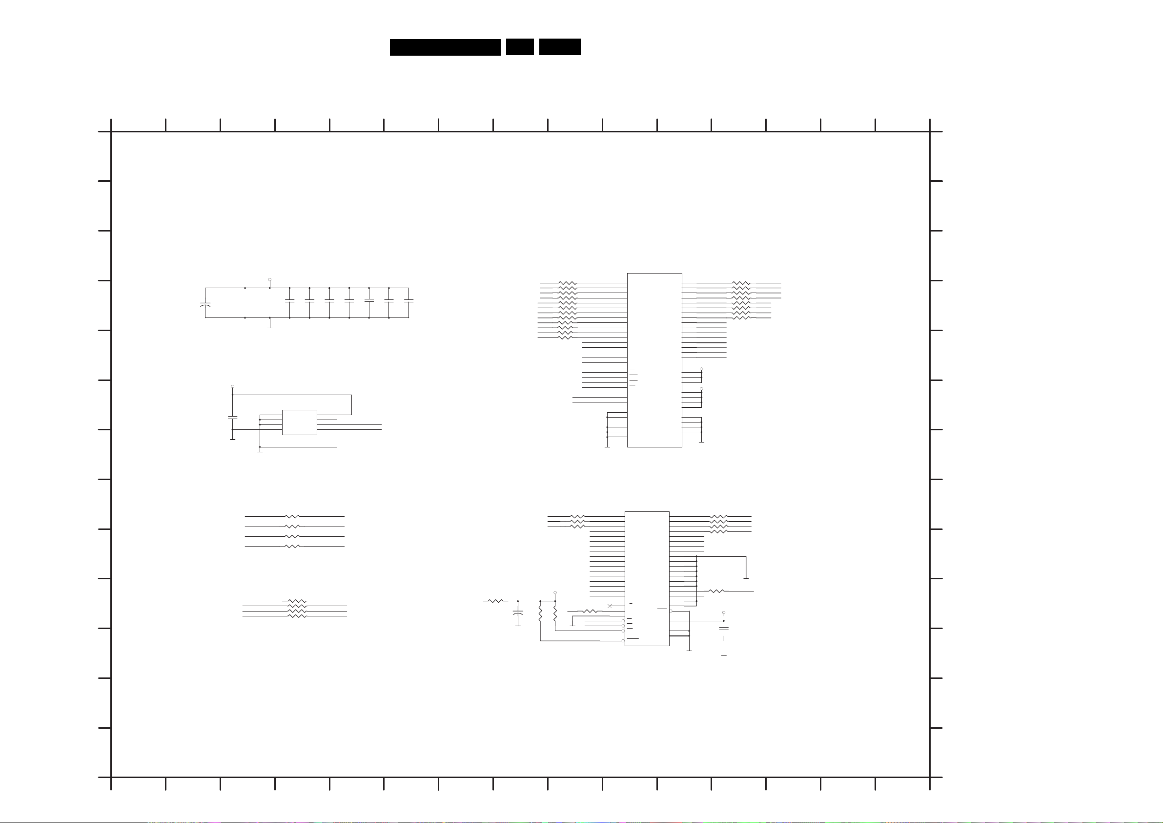
Electrical Diagrams MPEG DVP320
MPEG Board: Memory Part
DVP320
7.Electrical Diagrams and Print-layouts
EN 38
123456789101112131415
2710 D4
2711 D4
A
A
2712 D4
2713 D5
2714 D5
2715 D6
B
B
2716 D6
2720 F3
2777 K12
2793 D2
2812 J8
C
GND
7609
23
A0
24
A1
25
A2
26
A3
29
A4
30
A5
31
A6
32
A7
33
A8
34
A9
22
A10/AP
35
A11
20
BA0/A13
1
2
BA1/A12
38
CLK
37
CKE
19
CS
18
AS
R
17
CAS
16
WE
15
DQML
39
DQMH
36
NC
40
NC
54
VSS
41
VSS
28
VSS
MICRON MT48LC4M16A2-?
DQ0
DQ1
DQ2
DQ3
DQ4
DQ5
DQ6
DQ7
DQ8
DQ9
DQ10
DQ11
DQ12
DQ13
DQ14
DQ15
VCC
V
VCC
VCCQ
VCCQ
VCCQ
VCCQ
VSSQ
VSSQ
VSSQ
VSSQ
3818
Rx4
2
4
5
7
8
10
11
13
42
44
45
47
48
0
5
51
53
SD33
1
14
CC
27
SD33
3
9
43
49
6
12
46
52
GND
1 2
3 4
5 6
7 8
7 8
5 6
3 4
1 2
819
3
DQ9
DQ10
DQ11
DQ12
DQ13
DQ14
DQ15
DQ0
DQ1
DQ2
DQ3
DQ4
DQ5
DQ6
DQ7
Rx4
SD33
2713
2711
+
2793
D
220uF/16v A
GND
2710
0.1uF
0.1uF
2712
0.1uF
0.1uF
2714
0.1uF
2715
0.1uF
2716
0.1uF
3816
Rx4
E
DV3 3
GND
7610
1
NC
2
NC
3
NC
GND4SDA
EEPROM 24C16
VCC
SCL
8
7
WP
6
5
SCL
SDA
F
2720
0.1uF
GND
G
3815 8P4R
1 2
A0
M
3 4
MA1
5 6
MA2
7 8
MA3
1 2
MA4
3 4
MA5
5 6
MA6
7 8
MA7
3823
MA8 DQ8
3824
MA9
3825
MA10
3826
MA11
DQM0
DQM1
33R
33R
33R
33R
DBA0
DBA1
SDCLK
SDCKE
DCS#
DRAS#
DCAS#
DWE#
C
D
E
F
G
3672 H4
3673 I4
3674 I4
3675 I4
3676 J4
3679 J9
3680 J9
3746 J8
3808 J7
3815 C9
3816 D9
3818 C12
3819 D12
3823 D9
3824 E9
3825 E9
3826 E9
3851 I11
3855 H9
3856 H9
3857 I9
GND
3851
Rx4
7 8
5 6
3 4
1 2
AD4
AD5
AD6
AD7
33R
3865
A19
ASH
V-FL
GND
2777
0.1u
GND
AD0
AD1
AD2
AD3
A0
H
10K
3855
3856
3857
A20
GND
33R
33R
33R
A4
A5
A6
A7
A8
A9
A10
A11
A12
A13
A14
A15
A16
A17
A18
OPEN
9
367
PCE#
PRD#
PWR#
3672 33
BA0 DBA0
BA1
DCLK
3673 33
3674 33
3675 33
DBA1
SDCKEDCKE
SDCLK
A1
A2
A3
I
3676
CS#
S#
J
RA
CAS#
WE#
1 2
3 4
5 6
7 8
Rx4
DCS#
DRA
DCAS#
DWE#
S#
DV33
3808
33R
22uF/16v A
GND
V-FLASH
+
3746
2812
0R
3680
K
25
24
23
22
21
20
19
18
8
7
6
5
4
3
2
1
48
17
15
9
0
1
6
2
28
11
12
7611
A0
A1
A2
A3
A4
A5
A6
A7
A8
A9
A10
A11
A12
A13
A14
A15
A16
A17
RB
NC
NC
CE
OE
WE
SET
RE
M29W800AT-7
BYTE
VCC
GND1
GND2
D10
D11
D12
D13
D14
D15
A18
29
D0
31
D1
33
D2
35
D3
38
D4
40
D5
42
D6
44
D7
30
D8
32
D9
34
36
39
41
43
45
16
13
NC
14
NC
47
7
3
27
46
H
I
J
K
3865 J11
7609 C10
7610 F4
7611 H10
L
M
L
M
123456789101112131415
Page 39
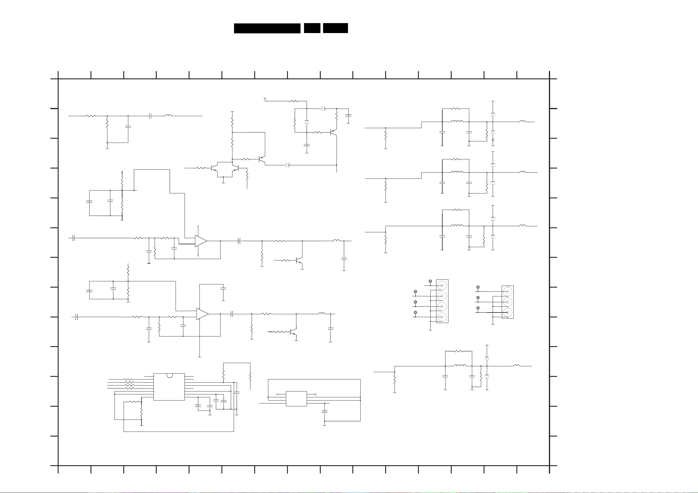
Electrical Diagrams and Print-layouts
DVP320
7.
EN 39
Electrical Diagrams MPEG DVP320
MPEG Board: Audio & Video Part
123456789101112131415
A
3877
10k
3873
OPEN
2751
3720
10K
33R
33R
33R
33R
2749
0.1uF
330p
3711
10K
2760
1n
GND
GND
1
VRST
2
3
4
5
6
7
8 9
3872
K
4.7
GND
5655
FB
2
371
3K3
3713
18K
2758
150P
3722
3K3
3727
18K
2765
1n
615
7
RST
SDATA
SCLK
LRCK
CS4340
MCLK
F1
DI
F0
DI
DEM0 FILT
CS4340A
2767
150P
MUTEC
AOUTA
AOUTB
RE
AGND
F_GND
VA
VQ
MUTE
16
15
14
13
12
11
10
2796
1uF/16V
COAX
3604 4.7K
84
3
+
2
-
+12VOP
84
5
+
6
-
GND
MUTE0
L
R
+
ASPDIF
B
3703
100
GND
3704
100
C
+12VOP
3879
2810
0.1u
10k
3880
10k
D
+
2811
220uF/25V
E
GND
2763
R
F
G
H
+
10uF/25v A
2770
L
10uF/25v A
+12VOP
3876
10k
+
2814
220uF/25v A
+
2813
0.1u
GND
I
J
3728
ASDAT 0
23
37
BCK
A
24
37
ALRCK
3721
ACL K
K
L
M
123456789101112131415
7613A
NJM4558
7613B
4558
0.1U
2800
GND
1606 H14
1614 I12
2722 B12
2723 B13
2725 D12
2726 D13
+12V
+12V
3606
0R
3602
3K
3603 1k
3743
10K
5707
FB/OPEN
GND
470R
3716
10K
3725
7616
BC857B
A_MU TE
7B
2768
0.1u
2806
+
10uF/25v A
+5V
3874
0R
2808
+
/1U
7633
BC847B
+
2805
10uF/25v A
DD
798
2
0.1U
GND
3607
4
MUTE0
GND
.7K
VCC
7635
BC84
GND
1
GND
7
2764
0.1U
16V
3742
470R
A_MU TE
1.5K
3608
1.5K
3717
6622
1N4148
5
6
7
8
7614
7805
3609
0R
NC
GND
GND
IN
3610
100k
GND
7629
BC
GND
847
GND
GND
OUT
GND
7628
BC847
NC
6621 BAS316
6623
BAS316
3605
2k2
+
2779
100UF/16V A
4
3
2
1
5660
FB
GND
+5VDD+12V
+
2807
47UF/16v A
3881
0R
7617
BC857B
A_MU TE
5661
FB
L_OUT
2769
680p/OPEN
GND
GND
2778
+
22u
R_OUT
2762
680p/O
PEN
+5VV
3687
10R
5615
Y6
3683
,1%
150
GND
Y4
3686
150,1%
GND
Y5
3690
150,1%
GND
TP34
R/V
TP33
B/U
32
TP
TP31
Y3
3699
150,1%
GND
G/Y
CVBS
GND
1.8uH
2723
2722
220p
100pF
3688
10R
5616
1.8uH
2725
100pF
220p
GND
3689
10R
5617
1.8uH
2731
2730
100pF
220p
GND GND GND
1614
8
7
6
5
4
3
2
1
RCA-414
3685
10R
5620
.8uH
1
2744
100pF
220p
2726
2745
GND
TP36
TP35
3694
15
3691
150,1%
3692
150,1%
3693
150,1%
TP37
0,1%
R_OUT
L_OUT
+5VV
GNDGNDGND
COAX
GNDGNDGND
+5VV
GND
+5VV
GND
6612
BAS3
6613
BAS316
6606
BAS316
6607
BAS316
6608
BAS316
6609
BAS316
6610
BAS316
6611
BAS
16
316
1606
6
5
4
3
2
1
RCA-314
5653
FB
5650
FB
5651
FB
5652
FB
R/V
CVBS
A
B
C
G/Y
D
E
B/U
F
G
H
I
J
K
L
GND
2730 F12
2731 F13
2744 J12
2745 J13
2749 B3
2751 B3
2758 F4
2760 F3
2762 G9
2763 F1
2764 K5
2765 I3
2767 I4
2768 H5
2769 I9
2770 H1
2778 B9
2779 C8
2796 K5
2798 K6
2800 K5
2805 F6
2806 I6
2807 L9
2808 K5
2810 E2
2811 E1
2813 H2
2814 H1
3602 C6
3603 C6
3604 D5
3605 B9
3606 B6
3607 D6
3608 I7
3609 A8
3610 B8
3683 C11
3685 J13
3686 D11
3687 A13
3688 C13
3689 E13
3690 F11
3691 C14
3692 D14
3693 F14
3694 K14
3699 K11
3703 B1
M
3704 B2
3711 F3
3712 F4
3716 G7
3717 G8
3720 I3
3721 K3
3722 I4
3723 K3
3724 K3
3725 I7
3727 I4
3728 K3
3742 F7
3743 I6
3872 L3
3873 K3
3874 J5
3876 G3
3877 H3
3879 D2
3880 E2
3881 B9
5615 B13
5616 D13
5617 E13
5620 J13
5650 B15
5651 D15
5652 E15
5653 J14
5655 B4
5660 H8
5661 F9
5707 J6
6606 B14
6607 B14
6608 D14
6609 D14
6610 E14
6611 F14
6612 J14
6613 K14
6621 A8
6622 C7
6623 B8
7613 F5
7613 H5
7614 L8
7615 K4
7616 C7
7617 B9
7628 G8
7629 I8
7633 C6
7635 C5
TP31 H12
TP32 H12
TP33 H12
TP34 G12
TP35 H13
TP36 H13
TP37 G13
3713 F4
Page 40
DVP320
7.Electrical Diagrams and Print-layouts
EN 40
Personal Notes:Personal Notes:
Page 41
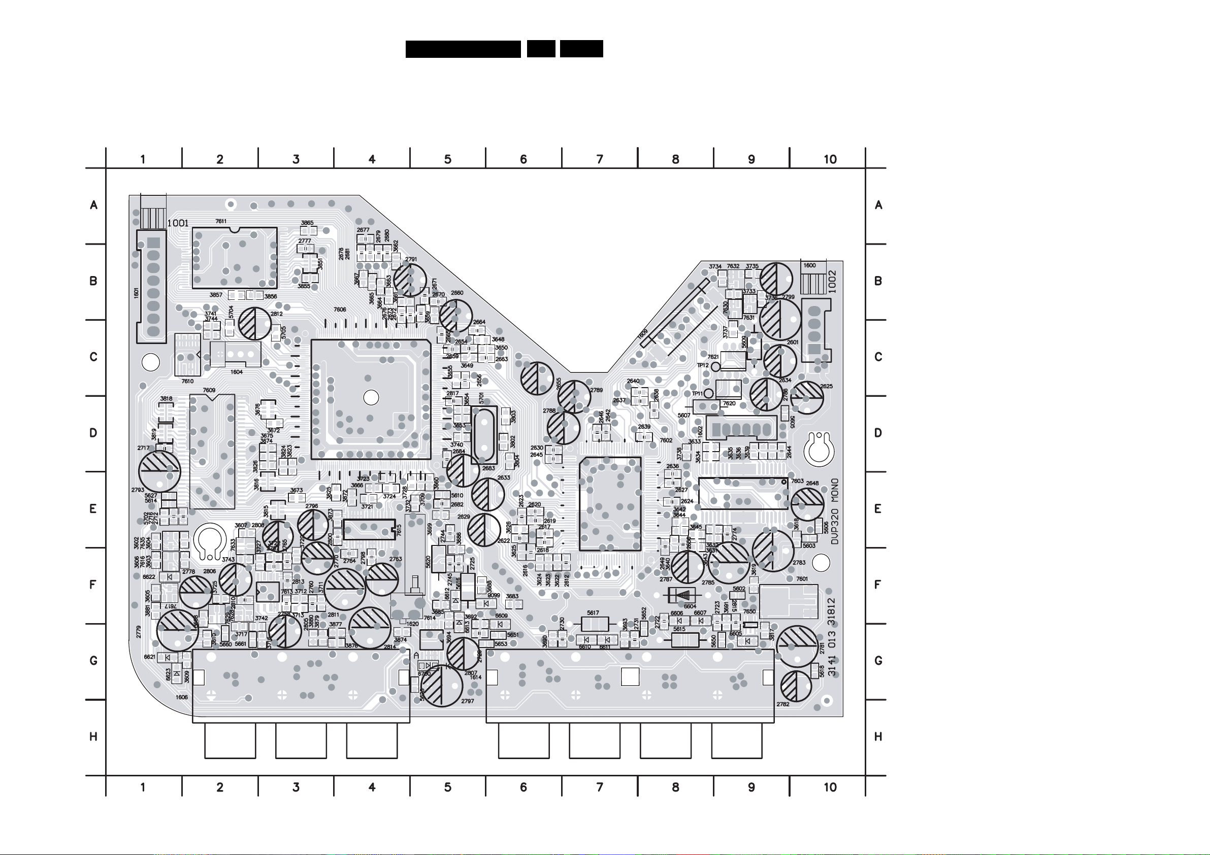
Electrical Diagrams and Print-layouts
Layout MPEG (3141 013 3181.2)
DVP320
7.
EN 41
Components Side
1600 C10
1601 A1
1602 D9
1604 C2
1606 G2
1609 C8
1614 G6
1620 F4
2601 B10
2612 F7
2616 F6
2617 E6
2618 E6
2619 E6
2620 E6
2622 E6
2623 E6
2624 E8
2625 D10
2627 E8
2629 E6
2630 D6
2633 E6
2634 C10
2636 E8
2637 D7
2638 D8
2639 D8
2640 C7
2642 D7
2644 D9
2645 D6
2646 D7
2648 E10
2649 F8
2650 E8
2654 C5
2655 C6
2656 C5
2659 C5
2660 B5
2663 C6
2664 C5
2665 C5
2670 B5
2671 B5
2672 B5
2673 B5
2676 B4
2677 A4
2678 B4
2679 B4
2680 B4
2681 B4
2682 E5
2683 D5
2684 D5
2712 E2
2716 E1
2717 D1
2722 G8
2723 G9
2725 F5
2726 G5
2730 G7
2731 G7
2744 E5
2745 F5
2758 F3
2760 F3
2763 F4
2764 F4
2765 F3
2767 F3
2770 F3
2774 E9
2777 B3
2778 F2
2779 G1
2781 G10
2782 G10
2783 F9
2785 F9
2786 C9
2787 F8
2788 D7
2789 D7
2791 B5
2793 E1
2796 E3
2797 G5
2798 F4
2799 B9
2800 E4
2805 G3
2806 F2
2807 G5
2808 E3
2810 F2
2811 F4
2812 C3
2813 F3
2814 G4
2815 F9
2817 D5
3602 E1
3603 F2
3604 E2
3605 F1
3606 F1
3607 E2
3608 F2
3609 G2
3610 G2
3618 E10
3619 F9
3622 F6
3623 F6
3624 F6
3625 F6
3626 E6
3631 E9
3632 E9
3633 D9
3634 D9
3635 D9
3636 D9
3639 D9
3640 E8
3642 E8
3643 E8
3644 E8
3645 E8
3648 C5
3649 C5
3650 C5
3653 D5
3654 D5
3655 C5
3659 B5
3660 E5
3661 B5
3662 B4
3663 B4
3664 B4
3665 B4
3666 E4
3667 B4
3672 D3
3673 E3
3674 D3
3675 D3
3676 D3
3683 F6
3685 F5
3686 F5
3688 F5
3690 G6
3691 F9
3692 G5
3693 G7
3694 G5
3699 E5
3709 E5
3711 F3
3712 F3
3713 F3
3716 G3
3717 G2
3720 F3
3721 E4
3722 F3
3723 E4
3724 E4
3725 F2
3727 F3
3728 E5
3732 E5
3733 B9
3734 B9
3735 B9
3736 B9
3738 D8
3740 D5
3741 C2
3742 G3
3743 F2
3744 C2
3802 D6
3803 D6
3804 D6
3815 E3
3816 E3
3817 G9
3818 D1
3819 D1
3823 D3
3824 D3
3825 E4
3826 D3
3851 B3
3855 B3
3856 B3
3857 B2
3865 A3
3872 E4
3873 E4
3874 G4
3876 G3
3877 G4
3879 G3
3880 G3
3881 F1
5602 F9
5603 E10
5605 D9
5606 E10
5607 D9
5609 C9
5610 E5
5614 E1
5615 G8
5616 F5
5617 G7
5618 G10
5620 F5
5623 G5
5627 E1
5650 G9
5651 G6
5652 G8
5653 G6
5660 G2
5661 G2
5701 D5
5702 E1
5704 C2
5705 C3
6604 F8
6605 G9
6606 F8
6607 F8
6608 F6
6609 G6
6610 G7
6611 G7
6612 F5
6613 F5
6621 G1
6622 F1
6623 G1
6700 G5
7601 F10
7602 D7
7603 D9
7606 C5
7609 D1
7610 C2
7611 A2
7613 F3
7614 G5
7615 E4
7616 F1
7617 F1
7620 C9
7621 C9
7628 F2
7629 F2
7630 B9
7631 B9
7632 B9
7633 E2
7635 E1
7650 G9
TP11 C8
TP12 C9
Page 42
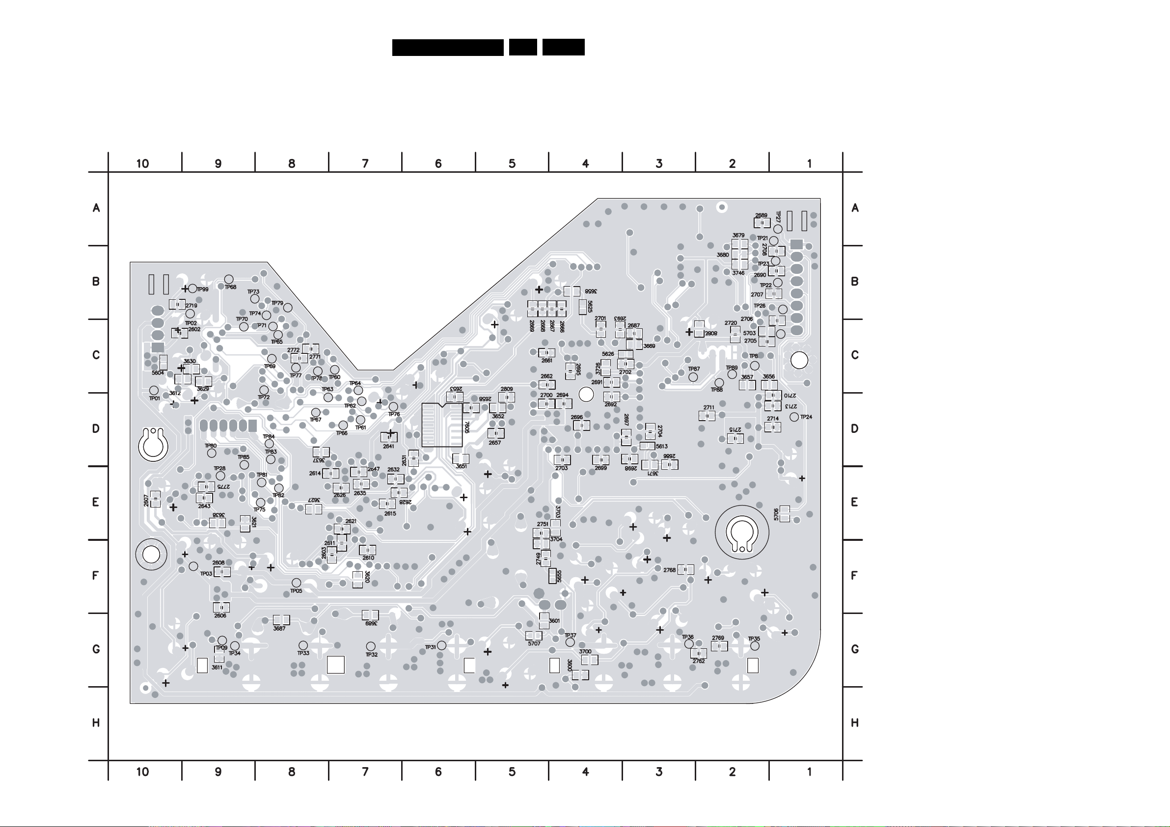
Layout MPEG (3141 013 3181.2)
DVP320
7.Electrical Diagrams and Print-layouts
EN 42
Bottom Side
2602 C10
2603 F7
2606 F9
2607 E10
2608 F9
2610 F7
2611 E7
2614 E8
2615 E7
2621 E7
2626 E7
2628 E6
2631 D6
2632 E7
2635 E7
2641 D7
2643 E9
2647 E7
2653 D6
2657 D5
2658 D6
2661 C4
2662 C5
2666 B4
2667 B4
2668 B5
2669 B5
2686 D3
2687 C3
2689 A2
2690 B1
2691 C4
2692 D4
2693 C4
2694 D4
2695 C4
2696 D4
2697 D3
2698 D3
2699 D4
2700 D5
2701 C4
2702 C3
2703 D4
2704 D3
2705 C2
2706 C1
2707 B1
2708 B1
2710 D1
2711 D2
2713 D1
2714 D2
2715 D2
2719 B10
2720 C2
2749 F5
2751 E5
2762 G3
2768 F3
2769 G2
2771 C8
2772 C8
2775 E9
2809 D5
3600 G4
3601 G5
3611 G9
3612 C9
3620 F7
3621 E9
3627 E8
3629 C9
3630 C9
3637 D8
3638 E9
3651 D6
3652 D5
3656 C2
3657 C2
3658 B4
3669 C3
3671 D3
3679 A2
3680 B2
3687 G8
3689 G7
3700 G4
3703 E4
3704 F5
3726 C4
3746 B2
3808 C2
5604 C10
5613 D3
5625 B4
5626 C3
5655 F4
5703 C2
5706 E1
5707 G5
7605 D6
TP01 C10
TP02 B9
TP03 F9
TP05 F8
TP09 G9
TP21 A1
TP22 B1
TP23 B1
TP24 D1
TP25 C1
TP26 B1
TP27 A1
TP28 E9
TP31 G6
TP32 G7
TP33 G8
TP34 G9
TP35 G2
TP36 G3
TP37 G4
TP60 C7
TP61 D7
TP62 D7
TP63 D8
TP64 C7
TP65 C8
TP66 D7
TP67 D8
TP68 B9
TP69 C8
TP70 C9
TP71 C8
TP72 C8
TP73 B9
TP74 B8
TP75 E8
TP76 D7
TP77 C8
TP78 C8
TP79 B8
TP80 D9
TP81 E8
TP82 E8
TP83 D8
TP84 D8
TP85 D9
TP86 C2
TP87 C3
TP88 C2
TP89 C2
TP99 B9
Page 43
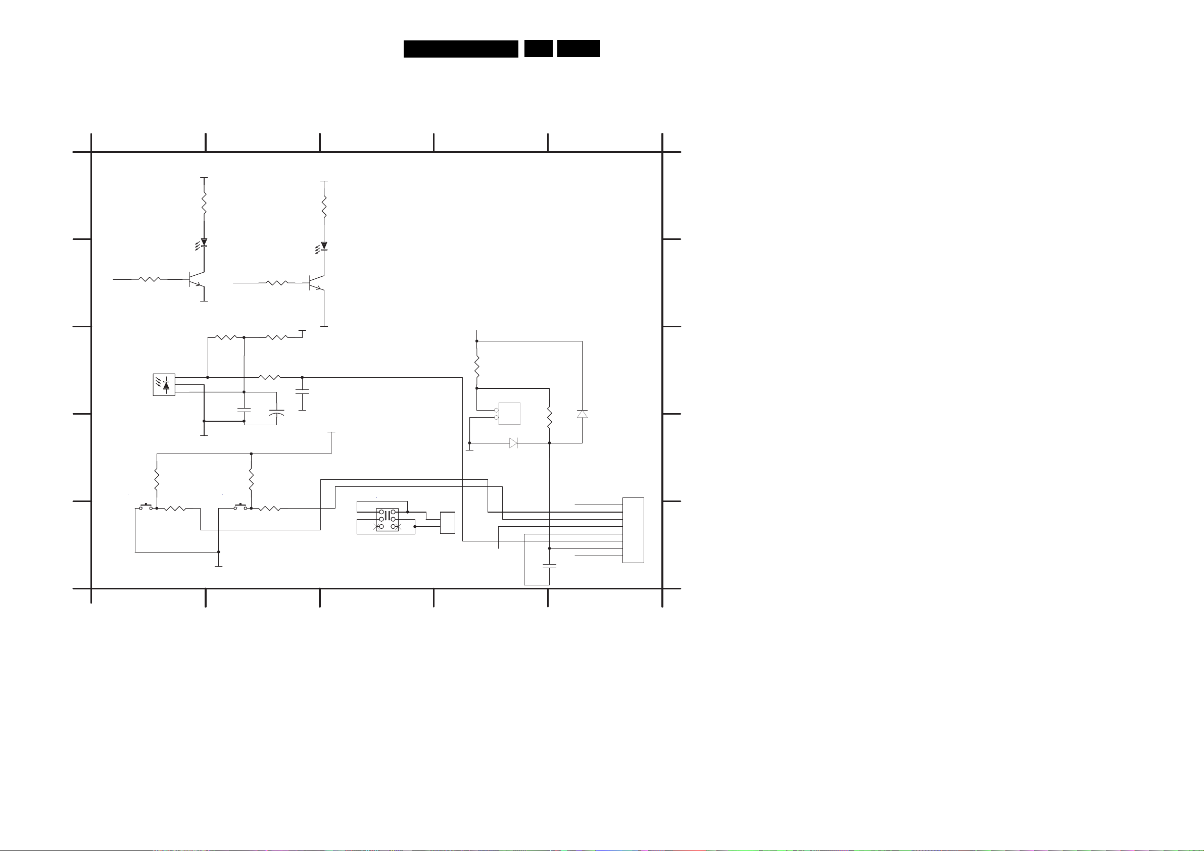
Electrical Diagrams and Print-layouts
Electrical Diagrams Front DVP320
1 2345
VCC
1
*3402
2.2K (except /93)
750R (for /93)
+
6402
+
DIODE-LE
-
7401
BC847
2 3
GND
10K
GND
STBY
3404
470
3407
47R
3406
1K
2401
1
100n
+
A
3403
B
C
LED
470
6403
1
2
3
IR_RECEIVER
D
1401
SW-KEY1
3408
10K
3411
1K
1402
KEY1 KEY2
SW-KEY1
3409
10K
3412
1K
E
GND
1
VCC3405
1
2400
GND
16V/10U
VCC
+
-
7402
BC847
2 3
GND
2402
100pF/ OPEN
VCC
*3401
2.2K (except /93)
1K (for /93)
6401
+
DIODE-LE
RC
SW1
SW2
1407
POWER
DVP320
7.
EN 43
1401 E1
1402 E2
1405 D4
A
1406 E4
1407 E3
1409 E5
2400 C2
2401 C2
2402 C2
2403 E4
B
3401 A2
3402 A1
3403 B1
VCC
3404 B2
3405 C2
3406 C2
3413
10K
C
3407 C2
3408 D1
3409 D2
3410 D5
3411 E1
3412 E2
3413 C4
6401 B3
6402 B1
6403 C1
GND
1405
2
1
HEADER 2
6406
3410
120R
6405
BAS316
D
6405 D5
1409
1
2
3
1406
1
2
DIPMATE
LED
KEY 1
KEY 2
VCC
GND
RC
OPEN/CLOSE
STBY
1
2403
100P
8
1
7
2
6
3
5
4
4
5
3
6
2
1
HEADER8
E
6406 D4
7401 B1
7402 B2
1 2345
Page 44
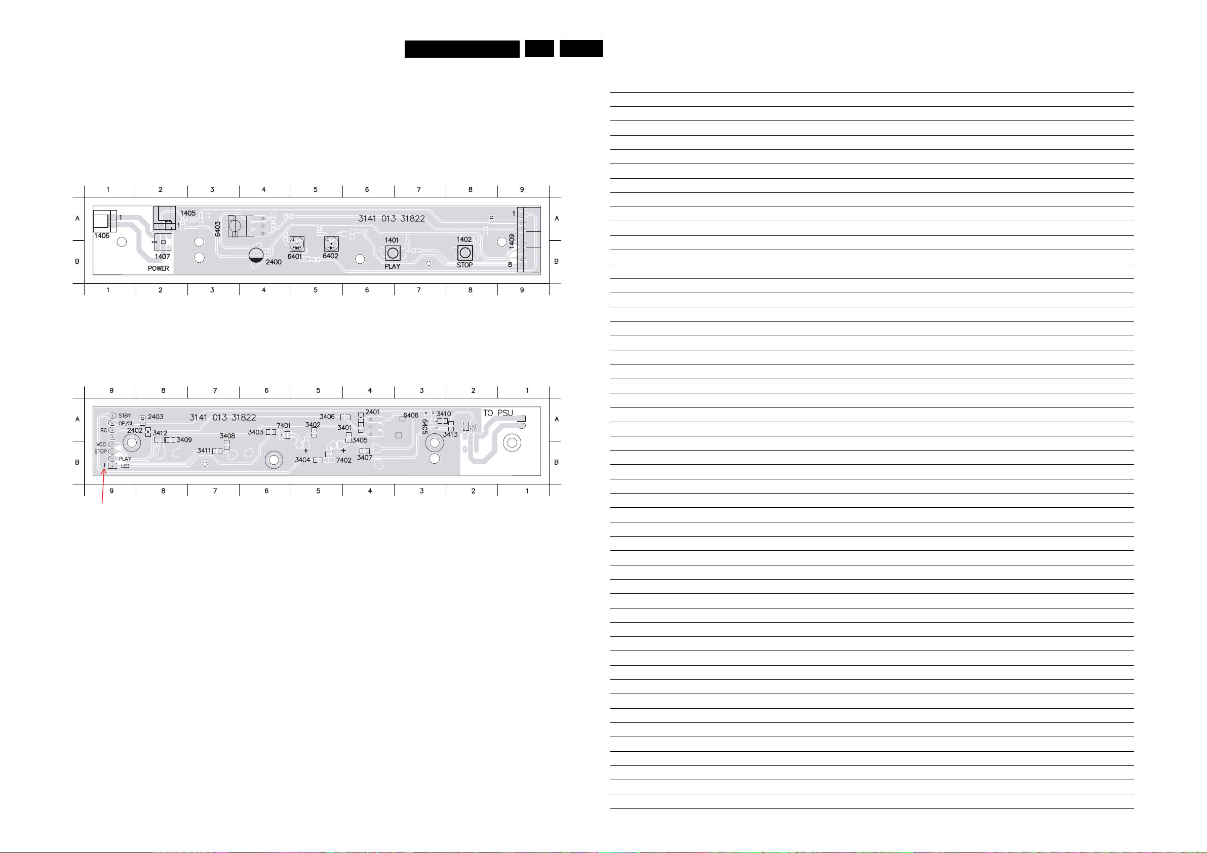
DVP320
7.Electrical Diagrams and Print-layouts
EN 44
Layout Front DVP320 PCB 3141 013 31822
Components Side
1401 B6
1402 B8
1405 A2
Copper Side
2401 A4
2402 A8
2403 A8
1406 A1
1407 B2
1409 B9
3401 A4
3402 A5
3403 A6
2400 B4
6401 B5
6402 B5
3404 B5
3405 A4
3406 A4
6403 A4
3407 B4
3408 B7
3409 A8
3410 A3
3411 B7
3412 A8
3413 A2
6405 A3
6406 A3
Personal Notes:
7401 A6
7402 B5
Note: The screen print is wrong, the number "1" should be "8".
Page 45
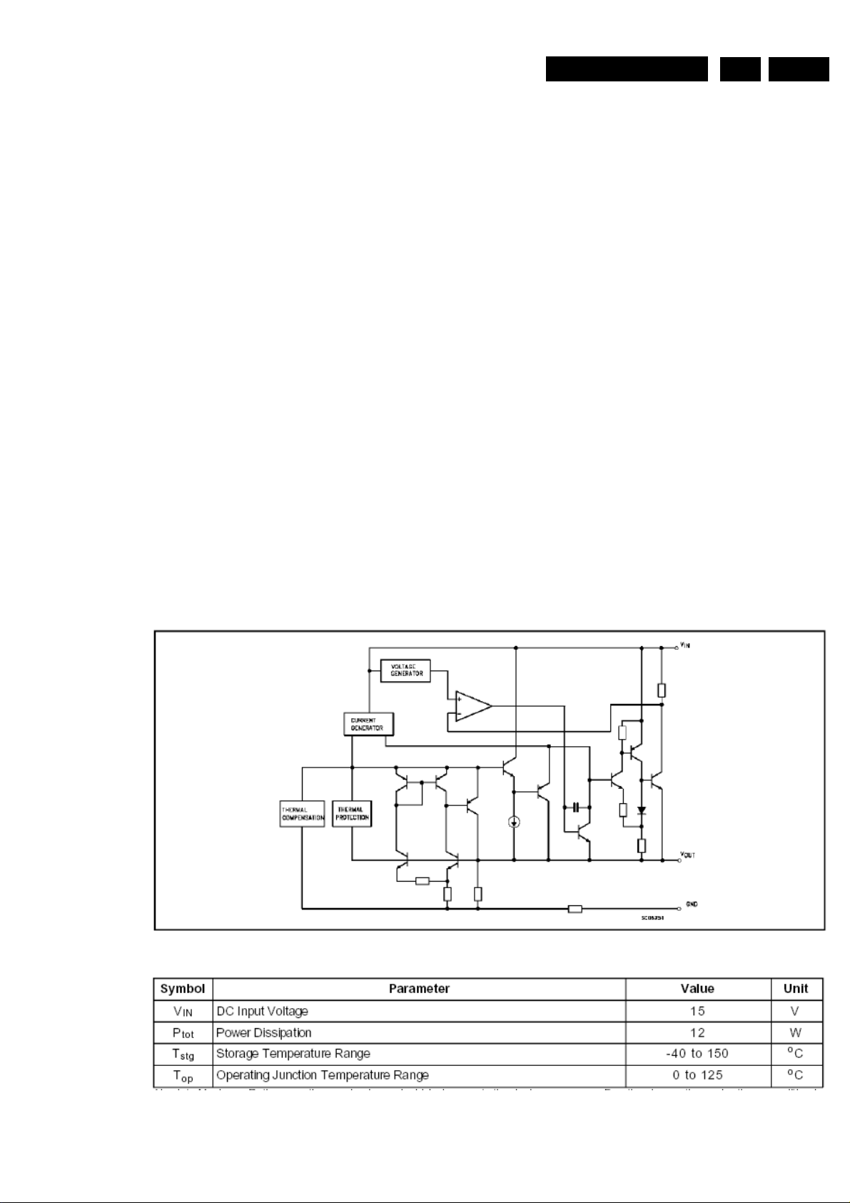
DVP320
9
9
9
9
9
9.Circuit descriptions and List of abbreviations EN 45
8 Electrical alignments
Not available
9 Circuit descriptions
Refer to Service Training SD5.42 MTK. 12NC: 3122 785 12820 for IC MT1379, MT1366, BA5954
.1 Regulator LD1117DT
.1.1 Features
• Low drop out voltage (1V Typ)
.1.2 Description
.1.3 BLOCK DIAGRAM
• 2.85V device performance are suitable for SCSI-2 active
• Output current up to 800 mA
• Fixed output voltage of 2.5V, 2.85V, 3.0V, 3.3V, 5.0V
• Adjustable version availability (V
• Internal current and thermal
• Available in ± 1% (at 25
• Supply voltage ejection: 75 dB (Typ)
• Temperature range: 0
The LD1117DT33 is a LOW DROP Voltage Regulator able to provide up to 800mA of Output Current, available even in adjustable
version (Vref=1.25V). Concerning fixed versions, are offered the following Output Voltages: 2.5V, 2.85V, 3.0V 3.3V and 5.0V. The
2.85V type is ideal for SCSI-2 lines active termination. The device is supplied in: SOT-223, DPAK, SO-8 and TO-220. The SOT-223
and DPAK surface mount packages optimize the thermal characteristics even offering a relevant space saving effect. High efficiency
is assured by NPN pass transistor. In fact in this case, unlike than PNP one, the Quiescent Current flows mostly into the load. Only a
very common 10mF minimum capacitor is needed for stability. On chip trimming allows the regulator to reach a very tight output
voltage tolerance, within ± 1% at 25
voltage regulators maintaining the better performances in terms of Drop and Tolerance.
o
C) and 2% in full temperature range
o
C to 125oC
ref
=1.25V)
o
C. The ADJUSTABLE LD1117 is pin-to-pin compatible with the other standard Adjustable
.1.4 Absolute maximum ratings
Absolute Maximum Ratings are those values beyond which damage to the device may occur. Functional operation under these
conditions is not implied. Over the above suggested Max Power Dissipation a Short Circuit could definitively damage the device.
Page 46
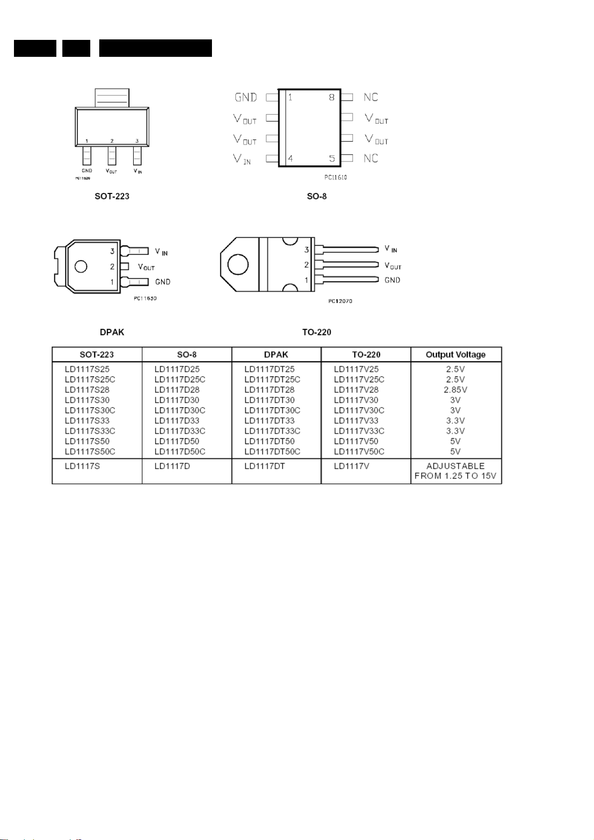
9. Circuit descriptions and List of abbreviationsEN 46
9
9
9
9
9
.1.5 Layout diagrams and ordering numbers (top view)
DVP320
.2 NCP302
.2.1 Description
The NCP302 and NCP303 series are second generation ultra–low current voltage detectors that contain a programmable time delay
.2.2 Features
.2.3 Typical Applications
generator. These devices are specifically designed for use as reset controllers in portable microprocessor based systems where
extended battery life is paramount.
Each series features a highly accurate under voltage detector with hysteresis and an externally programmable time delay generator.
This combination of features prevents erratic system reset operation.
The NCP302 series consists of complementary output devices that are available with either an active high or active low reset. The
NCP303 series has an open drain N–channel output with an active low
• Quiescent Current of 0.5 µA Typical
• High Accuracy Under Voltage Threshold of 2.0%
• Externally Programmable Time Delay Generator
• Wide Operating Voltage Range of 0.8 V to 10 V
• Complementary or Open Drain Output
• Active Low or Active High Reset
• Microprocessor Reset Controller
• Low Battery Detection
• Power Fail Indicator
• Battery Backup Detection
reset output.
Page 47
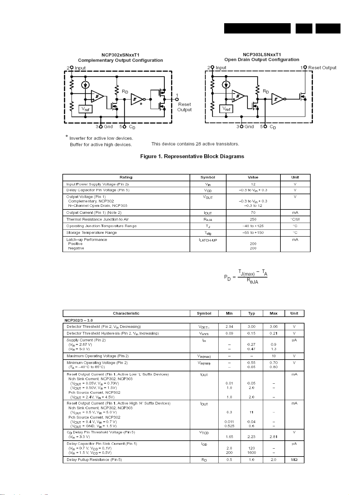
DVP320
9
9
9
.2.4 Block diagrams
.2.5 MAXIMUM RATINGS
9.Circuit descriptions and List of abbreviations EN 47
1. This device series contains ESD protection and exceeds the following tests:
Human Body Model 2000 V per MIL–STD–883, Method 3015.
Machine Model Method 200 V.
2. The maximum package power dissipation limit must not be exceeded.
.2.6 ELECTRICAL CHARACTERISTICS
A
(For all values T
= 25°C, unless otherwise noted.)
Page 48
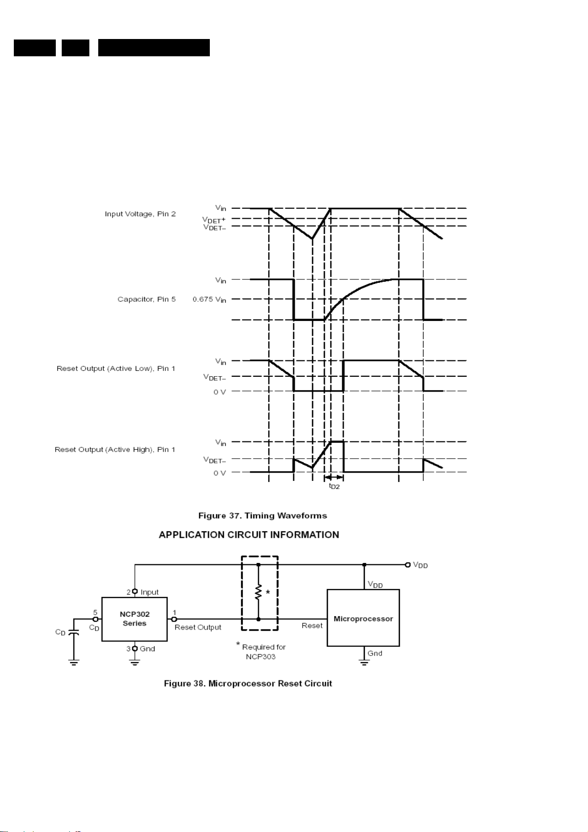
9. Circuit descriptions and List of abbreviationsEN 48
9
.2.7 OPERATING DESCRIPTION
The NCP302 and NCP303 series devices consist of a precision voltage detector that drives a time delay generator. Figures 37 and 38
show a timing diagram and a typical application. Initially consider that input voltage Vin is at a nominal level and it is greater than the
voltage detector upper threshold (VDET+). The voltage at Pin 5 and capacitor CD will be at the same level as Vin, and the reset
output (Pin 1) will be in the high state for active low devices, or in the low state for active high devices. If there is a power interruption
and Vin becomes significantly deficient, it will fall below the lower detector threshold (VDET–) and the external time delay capacitor
CD will be immediately discharged by an internal N–channel MOSFET that connects to Pin 5. This sequence of events causes the
Reset output to be in the low state for active low devices, or in the high state for active high devices. After completion of the power
interruption, Vin will again return to its nominal level and become greater than the VDET+. The voltage detector will turn off the
N–channel MOSFET and allow pull-up resistor RD to charge external capacitor CD, thus creating a programmable delay for releasing
the reset signal. When the voltage at Pin 5 exceeds the inverter/buffer threshold, typically 0.675 Vin, the reset output will revert back
to its original state. The voltage detector and inverter/buffer have built–in hysteresis to prevent erratic reset operation.
DVP320
Page 49
DVP320
10.Spare Parts List EN 49
10 Spare Parts List
10.1 Spare Parts List DVP320/69
ACCESSORIES DVP320/69
0381 2422 076 00304 CABLE CINCH/CINCH 1M5 YE/RD/WH
0384 3141 017 90351 REMOTE CONTROL DVP320-RC1
TECHNICAL SET DVP320/69
Various
0200 3141 017 79963 FRONT ASSY DVP320/69
0207 3141 011 60761 DOOR SPRING DVP320
0209 3141 011 21971 GASKET-PLATE
0211 3141 017 51091 BUTTON POWER PPT DVP320/69
0213 3141 017 79981 BOTTOM CABINET ASSY DVP320/69
0216 3140 111 21841 SPEAKER CLIP
0217 3141 011 21941 SHIELD FRAME DVP320
0219 3141 011 21951 SHIELD TOP DVP320
0221 3141 013 20531 WASHER LOADER DVP320
1001 3141 018 04371 DVD TRAVERSE KHM-280AHA (SONY)
1002 3141 018 04382 PBAS MONO BOARD DVP320
1003 3141 018 04392 PBAS FRONT DVP320
1005 3141 018 04931 PBAS PUS GAP MITSUMI WW AU/NZ
1006 8240 008 70121 CD DOOR SWITCH
5001 3141 018 71310 MAINS CORD 1.60M
8001 3141 010 21882 FFC 26P/150/26P 0.5MM FOLDED
8002 3141 010 21911 CWAS 8P/170/8P EH 2.5MM
8003 3141 010 21921 CWAS 6P/225/6P PH 2.0MM
8004 3141 010 21951 CWAS 2POP/50/2PEH
8005 3141 010 21932 CWAS 4P/175/4P EH 2.5MM
5701 3141 018 80600 CRYSTAL QUARTZ 27M
7601 9322 134 45668 LD1117DT33
7603 9322 187 63668 IC SM BA5954FP(RHM0) R
7611 3141 017 41163 FLASH ASSY GAP-PH
7614 9322 043 00668 MC78L05ACD
7620 9322 133 00685 2SB1132
7621 9322 133 00685 2SB1132
7630 3141 018 51690 TRA SM 2SK3018
7631 3141 018 51690 TRA SM 2SK3018
7650 9322 199 91685 IC SM NCP302HSN30 (ONSE) R
FRONT BOARD DVP320/69
1401 2422 128 02496 SWITCH, PUSH BUTTON
1402 2422 128 02496 SWITCH, PUSH BUTTON
1407 3141 018 40231 SWI PUSH 2P PSA-22D02LO LUPFUNG
6401 3141 018 51881 LED RED DIF LTL-4221N
6402 3141 018 51711 LED ORANGE
6403 3141 010 50391 IR TSOP4836-LL1 (VISHAY)
8401 3141 010 21941 CWAS 2P/70/2P EH 2.5MM
FRONT CABINET ASSY DVP320/69
0010 3141 017 79991 TOP CABINET PPT DVP320/69
0020 3141 017 50561 BUTTON TREE PPT DVP320
0040 3141 017 79971 DOOR ASSY DVP320/69
0050 4822 529 10322 DAMPER ASSY /78
0050 3139 118 73621 DAMPER ASSY /93 /69 /75
0070 3141 013 20581 PC SHEET COVER L DVP320
0080 3141 013 20591 PC SHEET COVER R DVP320
0090 3141 013 10041 FELT 7
BOTTOM CABINET ASSY DVP320/69
0020 3141 013 20521 CUSHION FOOT DVP320
MONO BOARD DVP320/69
1609 3141 010 30541 CON FPC BOTTOM SM 0.5MM 26P
1620 2422 128 02604 SPPB62010A
Page 50
10. Spare Parts ListEN 50
DVP320
10.2 Spare Parts List DVP320/75
ACCESSORIES DVP320/75
0381 2422 076 00304 CABLE CINCH/CINCH 1M5 YE/RD/WH
0384 3141 017 90351 REMOTE CONTROL DVP320-RC1
TECHNICAL SET DVP320/75
Various
0200 3141 017 79961 FRONT ASSY DVP320/69
0207 3141 011 60761 DOOR SPRING DVP320
0209 3141 011 21971 GASKET-PLATE
0211 3141 017 51091 BUTTON POWER PPT DVP320/69
0213 3141 017 79981 BOTTOM CABINET ASSY DVP320/69
0216 3140 111 21841 SPEAKER CLIP
0217 3141 011 21941 SHIELD FRAME DVP320
0219 3141 011 21951 SHIELD TOP DVP320
0221 3141 013 20531 WASHER LOADER DVP320
1001 3141 018 04371 DVD TRAVERSE KHM-280AHA (SONY)
1002 3141 018 04382 PBAS MONO BOARD DVP320
1003 3141 018 04392 PBAS FRONT DVP320
1005 3141 018 04931 PBAS PUS GAP MITSUMI WW AU/NZ
1006 8240 008 70121 CD DOOR SWITCH
5001 2422 070 98148 MAINSCORD AUS 1M9 BK B
8001 3141 010 21882 FFC 26P/150/26P 0.5MM FOLDED
8002 3141 010 21911 CWAS 8P/170/8P EH 2.5MM
8003 3141 010 21921 CWAS 6P/225/6P PH 2.0MM
8004 3141 010 21951 CWAS 2POP/50/2PEH
8005 3141 010 21932 CWAS 4P/175/4P EH 2.5MM
7614 9322 043 00668 MC78L05ACD
7620 9322 133 00685 2SB1132
7621 9322 133 00685 2SB1132
7630 3141 018 51690 TRA SM 2SK3018
7631 3141 018 51690 TRA SM 2SK3018
7650 9322 199 91685 IC SM NCP302HSN30 (ONSE) R
FRONT BOARD DVP320/75
1401 2422 128 02496 SWITCH, PUSH BUTTON
1402 2422 128 02496 SWITCH, PUSH BUTTON
1407 3141 018 40231 SWI PUSH 2P PSA-22D02LO LUPFUNG
6401 3141 018 51881 LED RED DIF LTL-4221N
6402 3141 018 51711 LED ORANGE
6403 3141 010 50391 IR TSOP4836-LL1 (VISHAY)
8401 3141 010 21941 CWAS 2P/70/2P EH 2.5MM
FRONT CABINET ASSY DVP320/75
0010 3141 017 79991 TOP CABINET PPT DVP320/69
0020 3141 017 50561 BUTTON TREE PPT DVP320
0040 3141 017 79971 DOOR ASSY DVP320/69
0050 4822 529 10322 DAMPER ASSY /78
0050 3139 118 73621 DAMPER ASSY /93 /69 /75
0070 3141 013 20581 PC SHEET COVER L DVP320
0080 3141 013 20591 PC SHEET COVER R DVP320
0090 3141 013 10041 FELT 7
BOTTOM CABINET ASSY DVP320/75
0020 3141 013 20521 CUSHION FOOT DVP320
MONO BOARD DVP320/75
1609 3141 010 30541 CON FPC BOTTOM SM 0.5MM 26P
1620 2422 128 02604 SPPB62010A
5701 3141 018 80600 CRYSTAL QUARTZ 27M
7601 9322 134 45668 LD1117DT33
7603 9322 187 63668 IC SM BA5954FP(RHM0) R
7611 3141 017 41163 FLASH ASSY GAP-PH
Page 51
DVP320
10.Spare Parts List EN 51
10.3 Spare Parts List DVP320/78
ACCESSORIES DVP320/78
0381 2422 076 00304 CABLE CINCH/CINCH 1M5 YE/RD/WH
0384 3141 017 90351 REMOTE CONTROL DVP320-RC1
TECHNICAL SET DVP320/78
Various
0200 3141 017 79961 FRONT ASSY DVP320/69
0207 3141 011 60761 DOOR SPRING DVP320
0209 3141 011 21971 GASKET-PLATE
0211 3141 017 51091 BUTTON POWER PPT DVP320/69
0213 3141 017 51141 BOTTOM CABINET ASSY DVP320/78
0216 3140 111 21841 SPEAKER CLIP
0217 3141 011 21941 SHIELD FRAME DVP320
0219 3141 011 21951 SHIELD TOP DVP320
0221 3141 013 20531 WASHER LOADER DVP320
1001 3141 018 04371 DVD TRAVERSE KHM-280AHA (SONY)
1002 3141 018 04382 PBAS MONO BOARD DVP320
1003 3141 018 04392 PBAS FRONT DVP320
1005 3141 018 04931 PBAS PUS GAP MITSUMI WW AU/NZ
1006 4822 276 13963 CD DOOR SWITCH
5001 3141 018 71310 MAINS CORD 1.60M
8001 3141 010 21882 FFC 26P/150/26P 0.5MM FOLDED
8002 3141 010 21911 CWAS 8P/170/8P EH 2.5MM
8003 3141 010 21921 CWAS 6P/225/6P PH 2.0MM
8004 3141 010 21951 CWAS 2POP/50/2PEH
8005 3141 010 21932 CWAS 4P/175/4P EH 2.5MM
7614 4822 209 33411 MC78L05ACD
7620 4822 130 11565 2SB1132
7621 4822 130 11565 2SB1132
7630 3141 018 51690 TRA SM 2SK3018
7631 3141 018 51690 TRA SM 2SK3018
7650 9322 199 91685 IC SM NCP302HSN30 (ONSE) R
FRONT BOARD DVP320/78
1401 2422 128 02496 SWITCH, PUSH BUTTON
1402 2422 128 02496 SWITCH, PUSH BUTTON
1407 3141 018 40231 SWI PUSH 2P PSA-22D02LO LUPFUNG
6401 3141 018 51881 LED RED DIF LTL-4221N
6402 3141 018 51711 LED ORANGE
6403 3141 010 50391 IR TSOP4836-LL1 (VISHAY)
8401 3141 010 21941 CWAS 2P/70/2P EH 2.5MM
FRONT CABINET ASSY DVP320/78
0010 3141 017 79991 TOP CABINET PPT DVP320/69
0020 3141 017 50561 BUTTON TREE PPT DVP320
0040 3141 017 79971 DOOR ASSY DVP320/69
0050 4822 529 10322 DAMPER ASSY /78
0050 3139 118 73621 DAMPER ASSY /93 /69 /75
0070 3141 013 20581 PC SHEET COVER L DVP320
0080 3141 013 20591 PC SHEET COVER R DVP320
0090 3141 013 10041 FELT 7
BOTTOM CABINET ASSY DVP320/78
0020 3141 013 20521 CUSHION FOOT DVP320
MONO BOARD DVP320/78
1609 3141 010 30541 CON FPC BOTTOM SM 0.5MM 26P
1620 4822 276 13503 SPPB62010A
5701 3141 018 80600 CRYSTAL QUARTZ 27M
7601 4822 209 17398 LD1117DT33
7603 9322 187 63668 IC SM BA5954FP(RHM0) R
7611 3141 017 41163 FLASH ASSY GAP-PH
Page 52
10. Spare Parts ListEN 52
DVP320
10.4 Spare Parts List DVP320/93
ACCESSORIES DVP320/93
0381 2422 076 00304 CABLE CINCH/CINCH 1M5 YE/RD/WH
0384 3141 017 90351 REMOTE CONTROL DVP320-RC1
TECHNICAL SET DVP320/93
Various
0200 3141 017 79961 FRONT ASSY DVP320/69
0207 3141 011 60761 DOOR SPRING DVP320
0209 3141 011 21971 GASKET-PLATE
0211 3141 017 51091 BUTTON POWER PPT DVP320/69
0216 3140 111 21841 SPEAKER CLIP
0217 3141 011 21941 SHIELD FRAME DVP320
0219 3141 011 21951 SHIELD TOP DVP320
0221 3141 013 20531 WASHER LOADER DVP320
1001 3141 018 04371 DVD TRAVERSE KHM-280AHA (SONY)
1002 3141 018 04382 PBAS MONO BOARD DVP320
1003 3141 018 05051 PBAS FRONT DVP320
1005 3141 018 05041 PBAS PUS GAP MITSUMI WW CH
1006 4822 276 13963 CD DOOR SWITCH
5001 3141 018 71411 MAINS CORD
8001 3141 010 21882 FFC 26P/150/26P 0.5MM FOLDED
8002 3141 010 21911 CWAS 8P/170/8P EH 2.5MM
8003 3141 010 21921 CWAS 6P/225/6P PH 2.0MM
8004 3141 010 21951 CWAS 2POP/50/2PEH
8005 3141 010 21932 CWAS 4P/175/4P EH 2.5MM
7620 9322 133 00685 2SB1132
7621 9322 133 00685 2SB1132
7630 3141 018 51690 TRA SM 2SK3018
7631 3141 018 51690 TRA SM 2SK3018
7650 9322 199 91685 IC SM NCP302HSN30 (ONSE) R
FRONT BOARD DVP320/93
1401 2422 128 02496 SWITCH, PUSH BUTTON
1402 2422 128 02496 SWITCH, PUSH BUTTON
1407 3141 018 40231 SWI PUSH 2P PSA-22D02LO LUPFUNG
6401 3141 018 51881 LED RED DIF LTL-4221N
6402 3141 018 51711 LED ORANGE
6403 3141 010 50391 IR TSOP4836-LL1 (VISHAY)
8401 3141 010 21941 CWAS 2P/70/2P EH 2.5MM
FRONT CABINET ASSY DVP320/93
0010 3141 017 79991 TOP CABINET PPT DVP320/69
0020 3141 017 50561 BUTTON TREE PPT DVP320
0040 3141 017 79971 DOOR ASSY DVP320/69
0050 4822 529 10322 DAMPER ASSY /78
0050 3139 118 73621 DAMPER ASSY /93 /69 /75
0070 3141 013 20581 PC SHEET COVER L DVP320
0080 3141 013 20591 PC SHEET COVER R DVP320
0090 3141 013 10041 FELT 7
BOTTOM CABINET ASSY DVP320/93
0020 3141 013 20521 CUSHION FOOT DVP320
MONO BOARD DVP320/93
1609 3141 010 30541 CON FPC BOTTOM SM 0.5MM 26P
1620 2422 128 02604 SPPB62010A
5701 3141 018 80600 CRYSTAL QUARTZ 27M
7601 9322 134 45668 LD1117DT33
7603 9322 187 63668 IC SM BA5954FP(RHM0) R
7611 3141 017 41163 FLASH ASSY GAP-PH
7614 9322 043 00668 MC78L05ACD
Page 53
DVP320
10.Spare Parts List EN 53
10.5 Spare Parts List DVP320/00
ACCESSORIES DVP320/00
0381 2422 076 00304 CABLE CINCH/CINCH 1M5 YE/RD/WH
0382 3141 010 30621 CON ASSY SCART/3CINCH AV
0384 3141 017 90351 REMOTE CONTROL DVP320-RC1
0387 3141 015 26361 IFU DVP320/00
0394 3141 019 10151 CD IFU DVP320
TECHNICAL SET DVP320/00
Various
0200 3141 017 79961 FRONT ASSY DVP320/69
0207 3141 011 60761 DOOR SPRING DVP320
0209 3141 011 21971 GASKET-PLATE
0211 3141 017 51091 BUTTON POWER PPT DVP320/69
0213 3141 017 79981 BOTTOM CABINET ASSY DVP320/69
0216 3140 111 21841 SPEAKER CLIP
0217 3141 011 21941 SHIELD FRAME DVP320
0219 3141 011 21951 SHIELD TOP DVP320
0221 3141 013 20531 WASHER LOADER DVP320
1001 3141 018 04371 DVD TRAVERSE KHM-280AHA (SONY)
1002 3141 018 05091 PBAS MONO BOARD DVP320/00
1003 3141 018 04392 PBAS FRONT DVP320
1005 3141 018 04931 PBAS PUS GAP MITSUMI AU/NZ
1006 4822 276 13963 CD DOOR SWITCH
5001 3141 018 71310 MAINS CORD 1.60M
8001 3141 010 21882 FFC 26P/150/26P 0.5MM FOLDED
8002 3141 010 21911 CWAS 8P/170/8P EH 2.5MM
8003 3141 010 21921 CWAS 6P/225/6P PH 2.0MM
8004 3141 010 21951 CWAS 2POP/50/2PEH
8005 3141 010 21932 CWAS 4P/175/4P EH 2.5MM
7601 4822 209 17398 LD1117DT33
7603 9322 187 63668 IC SM BA5954FP(RHM0) R
7611 3141 017 41381 FLASH ASSY GAP-PH-OLD-UI
7614 4822 209 33411 MC78L05ACD
7620 4822 130 11565 2SB1132
7621 4822 130 11565 2SB1132
7630 3141 018 51690 TRA SM 2SK3018
7631 3141 018 51690 TRA SM 2SK3018
7650 9322 199 91685 IC SM NCP302HSN30 (ONSE) R
FRONT BOARD DVP320/00
1401 2422 128 02496 SWITCH, PUSH BUTTON
1402 2422 128 02496 SWITCH, PUSH BUTTON
1407 3141 018 40231 SWI PUSH 2P PSA-22D02LO LUPFUNG
6401 3141 018 51881 LED RED DIF LTL-4221N
6402 3141 018 51711 LED ORANGE
6403 3141 010 50391 IR TSOP4836-LL1 (VISHAY)
8401 3141 010 21941 CWAS 2P/70/2P EH 2.5MM
FRONT CABINET ASSY DVP320/00
0010 3141 017 79991 TOP CABINET PPT DVP320/69
0020 3141 017 50561 BUTTON TREE PPT DVP320
0040 3141 017 79971 DOOR ASSY DVP320/69
0050 4822 529 10322 DAMPER ASSY /78
0050 3139 118 73621 DAMPER ASSY /93 /69 /75
0070 3141 013 20581 PC SHEET COVER L DVP320
0080 3141 013 20591 PC SHEET COVER R DVP320
0090 3141 013 10041 FELT 7
BOTTOM CABINET ASSY DVP320/00
0020 3141 013 20521 CUSHION FOOT DVP320
MONO BOARD DVP320/00
1609 3141 010 30541 CON FPC BOTTOM SM 0.5MM 26P
1620 4822 276 13503 SPPB62010A
5701 3141 018 80600 CRYSTAL QUARTZ 27M FUNDAMENTAL
Page 54
10. Spare Parts ListEN 54
DVP320
10.6 Spare Parts List DVP320/AK
ACCESSORIES DVP320/AK
0381 2422 076 00304 CABLE, COAXIAL
0384 3141 017 90351 REMOTE CONTROL
0387 3141 015 25461 DOC DIRECTIONS FOR USE
0388 3139 128 73010 ADAPTER, CONNECTOR
TECHNICAL SET DVP320/AK
Various
0200 3141 017 79961 FRONT PANEL, PLASTIC
0207 3141 011 60761 SPRING
0209 3141 011 21971 GASKET, PLASTIC
0211 3141 017 51091 PUSH BUTTON, PLASTIC
0213 3141 017 51381 HOUSING PART, PLASTIC
0216 3140 111 21841 CLIP, PLASTIC
0217 3141 011 21941 FRAME, STEEL
0219 3141 011 21951 TOP COVER, STEEL
0221 3141 013 20531 RING, STEEL
1001 3141 018 04371 MECH. UNIT, DVD PLAYER
1002 3141 018 04901 PR.CIRCUIT, DVD PLAYER
1003 3141 018 04392 PR.CIRCUIT, DVD PLAYER
1005 3122 429 00201 PR.CIRCUIT, DVD PLAYER
1006 4822 276 13963 SWITCH, PUSH BUTTON
5001 3141 018 71310 CORD, MAINS
8001 3141 010 21882 FLEXIBLE FOIL CONNECTION
8002 3141 010 21911 CABLE, CONNECTING
8003 3141 010 21921 CABLE, CONNECTING
8004 3141 010 21951 CABLE, CONNECTING
8005 3141 010 21932 CABLE, CONNECTING
7603 9322 187 63668 IC ANA OTHERS
7611 3141 017 41163 IC DIG MOS FL.EEPROM>4MB<=16MB
7614 4822 209 33411 IC ANA VOLT./CURR. REGULATOR
7620 4822 130 11565 TRANSISTOR, >=1W
7621 4822 130 11565 TRANSISTOR, >=1W
7630 3141 018 51690 TRANSISTOR, FET <1W
7631 3141 018 51690 TRANSISTOR, FET <1W
7650 9322 199 91685 IC ANA OTHERS
FRONT BOARD DVP320/AK
1401 2422 128 02496 SWITCH, PUSH BUTTON
1402 2422 128 02496 SWITCH, PUSH BUTTON
1407 3141 018 40231 SWI PUSH 2P PSA-22D02LO LUPFUNG
6401 3141 018 51881 LED RED DIF LTL-4221N
6402 3141 018 51711 LED ORANGE
6403 3141 010 50391 IR TSOP4836-LL1 (VISHAY)
8401 3141 010 21941 CWAS 2P/70/2P EH 2.5MM
FRONT CABINET ASSY DVP320/AK
0010 3141 017 79991 TOP CABINET PPT DVP320/69
0020 3141 017 50561 BUTTON TREE PPT DVP320
0040 3141 017 79971 DOOR ASSY DVP320/69
0050 4822 529 10322 DAMPER ASSY /78
0050 3139 118 73621 DAMPER ASSY /93 /69 /75
0070 3141 013 20581 PC SHEET COVER L DVP320
0080 3141 013 20591 PC SHEET COVER R DVP320
0090 3141 013 10041 FELT 7
BOTTOM CABINET ASSY DVP320/AK
0020 3141 013 20521 FOOT, PLASTIC
PBAS MONO BOARD DVP320/AK
1609 3141 010 30541 CONNECTOR, PRINTED CIRCUIT
1620 4822 276 13503 SWITCH, PUSH BUTTON
5701 3141 018 80600 CRYSTAL
7601 4822 209 17398 IC ANA VOLT./CURR. REGULATOR
Page 55
DVP320
10.Spare Parts List EN 55
10.7 Spare Parts List DVP320/BK
ACCESSORIES DVP320/BK
0381 2422 076 00304 CABLE, COAXIAL
0384 3141 017 90351 REMOTE CONTROL
0387 3141 015 25461 DOC DIRECTIONS FOR USE
0388 3139 128 73010 ADAPTER, CONNECTOR
TECHNICAL SET DVP320/BK
Various
0200 3141 017 79961 FRONT PANEL, PLASTIC
0207 3141 011 60761 SPRING
0209 3141 011 21971 GASKET, PLASTIC
0211 3141 017 51091 PUSH BUTTON, PLASTIC
0213 3141 017 51381 HOUSING PART, PLASTIC
0216 3140 111 21841 CLIP, PLASTIC
0217 3141 011 21941 FRAME, STEEL
0219 3141 011 21951 TOP COVER, STEEL
0221 3141 013 20531 RING, STEEL
1001 3141 018 04371 MECH. UNIT, DVD PLAYER
1002 3141 018 04901 PR.CIRCUIT, DVD PLAYER
1003 3141 018 04392 PR.CIRCUIT, DVD PLAYER
1005 3122 429 00201 PR.CIRCUIT, DVD PLAYER
1006 4822 276 13963 SWITCH, PUSH BUTTON
5001 3141 018 71310 CORD, MAINS
8001 3141 010 21882 FLEXIBLE FOIL CONNECTION
8002 3141 010 21911 CABLE, CONNECTING
8003 3141 010 21921 CABLE, CONNECTING
8004 3141 010 21951 CABLE, CONNECTING
8005 3141 010 21932 CABLE, CONNECTING
7603 9322 187 63668 IC ANA OTHERS
7611 3141 017 41163 IC DIG MOS FL.EEPROM>4MB<=16MB
7614 4822 209 33411 IC ANA VOLT./CURR. REGULATOR
7620 4822 130 11565 TRANSISTOR, >=1W
7621 4822 130 11565 TRANSISTOR, >=1W
7630 3141 018 51690 TRANSISTOR, FET <1W
7631 3141 018 51690 TRANSISTOR, FET <1W
7650 9322 199 91685 IC ANA OTHERS
FRONT BOARD DVP320/BK
1401 2422 128 02496 SWITCH, PUSH BUTTON
1402 2422 128 02496 SWITCH, PUSH BUTTON
1407 3141 018 40231 SWI PUSH 2P PSA-22D02LO LUPFUNG
6401 3141 018 51881 LED RED DIF LTL-4221N
6402 3141 018 51711 LED ORANGE
6403 3141 010 50391 IR TSOP4836-LL1 (VISHAY)
8401 3141 010 21941 CWAS 2P/70/2P EH 2.5MM
FRONT CABINET ASSY DVP320/BK
0010 3141 017 79991 TOP CABINET PPT DVP320/69
0020 3141 017 50561 BUTTON TREE PPT DVP320
0040 3141 017 79971 DOOR ASSY DVP320/69
0050 4822 529 10322 DAMPER ASSY /78
0050 3139 118 73621 DAMPER ASSY /93 /69 /75
0070 3141 013 20581 PC SHEET COVER L DVP320
0080 3141 013 20591 PC SHEET COVER R DVP320
0090 3141 013 10041 FELT 7
BOTTOM CABINET ASSY DVP320/BK
0020 3141 013 20521 FOOT, PLASTIC
PBAS MONO BOARD DVP320/BK
1609 3141 010 30541 CONNECTOR, PRINTED CIRCUIT
1620 4822 276 13503 SWITCH, PUSH BUTTON
5701 3141 018 80600 CRYSTAL
7601 4822 209 17398 IC ANA VOLT./CURR. REGULATOR
Page 56
10. Spare Parts ListEN 56
DVP320
10.8 Spare Parts List DVP323/05
ACCESSORIES DVP323/05
0381 2422 076 00304 CABLE, COAXIAL
0382 3141 010 30621 CON ASSY SCART/3CINCH AV
0384 3141 017 90351 REMOTE CONTROL
0387 3141 015 26461 DOC DIRECTIONS FOR USE
TECHNICAL SET DVP323/05
Various
0200 3141 017 79961 FRONT PANEL, PLASTIC
0207 3141 011 60761 SPRING
0209 3141 011 21971 GASKET, PLASTIC
0211 3141 017 51091 PUSH BUTTON, PLASTIC
0213 3141 017 79981 BOTTOM COVER, PLASTIC
0216 3140 111 21841 CLIP, PLASTIC
0217 3141 011 21941 FRAME, STEEL
0219 3141 011 21951 TOP COVER, STEEL
0221 3141 013 20531 RING, STEEL
1001 3141 018 04371 MECH. UNIT, DVD PLAYER
1002 3141 018 05091 PR.CIRCUIT, DVD PLAYER
1003 3141 018 04392 PR.CIRCUIT, DVD PLAYER
1005 3141 018 04931 POWER SUPPLY UNIT
1006 4822 276 13963 SWITCH, PUSH BUTTON
5001 4822 321 10713 CORD, MAINS
8001 3141 010 21882 FLEXIBLE FOIL CONNECTION
8002 3141 010 21911 CABLE, CONNECTING
8003 3141 010 21921 CABLE, CONNECTING
8004 3141 010 21951 CABLE, CONNECTING
8005 3141 010 21932 CABLE, CONNECTING
7603 9322 187 63668 IC SM BA5954FP(RHM0) R
7611 3141 017 41381 FLASH ASSY GAP-PH-OLD-UI
7614 4822 209 33411 MC78L05ACD
7620 4822 130 11565 2SB1132
7621 4822 130 11565 2SB1132
7630 3141 018 51690 TRA SM 2SK3018
7631 3141 018 51690 TRA SM 2SK3018
7650 9322 199 91685 IC SM NCP302HSN30 (ONSE) R
FRONT BOARD DVP323/05
1401 2422 128 02496 SWITCH, PUSH BUTTON
1402 2422 128 02496 SWITCH, PUSH BUTTON
1407 3141 018 40231 SWI PUSH 2P PSA-22D02LO LUPFUNG
6401 3141 018 51881 LED RED DIF LTL-4221N
6402 3141 018 51711 LED ORANGE
6403 3141 010 50391 IR TSOP4836-LL1 (VISHAY)
8401 3141 010 21941 CWAS 2P/70/2P EH 2.5MM
FRONT CABINET ASSY DVP323/05
0010 3141 017 79991 TOP CABINET PPT DVP320/69
0020 3141 017 50561 BUTTON TREE PPT DVP320
0040 3141 017 79971 DOOR ASSY DVP320/69
0050 4822 529 10322 DAMPER ASSY /78
0050 3139 118 73621 DAMPER ASSY /93 /69 /75
0070 3141 013 20581 PC SHEET COVER L DVP320
0080 3141 013 20591 PC SHEET COVER R DVP320
0090 3141 013 10041 FELT 7
BOTTOM CABINET ASSY DVP323/05
0020 3141 013 20521 CUSHION FOOT DVP320
MONO BOARD DVP323/05
1609 3141 010 30541 CON FPC BOTTOM SM 0.5MM 26P
1620 4822 276 13503 SPPB62010A
5701 3141 018 80600 CRYSTAL QUARTZ 27M FUNDAMENTAL
7601 4822 209 17398 LD1117DT33
Page 57

11 Revision List
11.1 Manual 3141 785 1376.1
1. Only for /93 version, change front PCBA board
from 3141 018 04392 to 3141 018 05051. Reduce
series resisters of LED to gain higher luminosity
of LED in front panel in /93 version.
• Resistor 3401 = 1 kilo-ohm;
• Resistor 3402 = 750 ohm
Page 41, 48 update accordingly.
2. For /93 version, change PSU from 3141 018
04531 to 3141 018 05041 before mass production.
Page 48 update accordingly.
3. For /75 version, change PSU from 3141 018
04531 to 3141 018 04931 before mass production.
Page 48 update accordingly.
DVP320
11.Revision List EN 57
4. Deleted the ferrite ring (item 5002) except /17
stroke version.
Page 30, 48 update accordingly.
11.2 Manual 3141 785 1376.2
1. Modified cover and add spare parts list of
DVP320/00 to include version /00.
2. Page 39: Correct the layout screen print from
3141 013 04382 to 3141 013 31812
3. Page 48: Change PSU of /93 from 3141 018
05041 to 3141 018 04931; PSU of /69 and /78
from 3141 018 04531 to 3141 018 04931;
11.3 Manual 3141 785 1376.3
1. Add the following information and modified the
cover to include version /BK and /AK
• PCB layout of PSU (EPM) 3122 429 00201;
• Schematics of PSU (EPM) 3122 429 00201;
• Spare partslists of DVP320/AK/BK.
2. Add spare partslist of DVP323/05 to include
model DVP323/05, which is same as DVP320/00
except packaging and mains cord
 Loading...