

Page 1
NOTICE DTR 500.qxd 7/09/2004 15:24 Page 1
Page 2

English
Welcome to digital television
Congratulations on choosing the Philips DTR 500 digital terrestrial receiver.Using your Philips digital
receiver will allow you to access Freeview digital terrestrial television,radio and interactive channels.
With this product, you can enjoy advanced functions and features including:
- Award-winning noise-free reception
- Automatic program installation
- Wide screen format
- TV SCART and VCR/DVD SCART connector
- Personal channel list and favourite lists
- Electronic Programme Guide
This User Manual covers the installation of your receiver and the necessary steps to use the various
functions,so you can optimally enjoy classic as well as unique features.
Lucas Covers
Paris,August 2004
2
WELCOME TO DIGITAL TELEVISION
NOTICE DTR 500.qxd 7/09/2004 15:24 Page 2
Page 3

English
Quick installation
Please read the safety section before connecting your receiver.
Requirements for fast and successful first installation are as follows:
• You already have an aerial.
• Your aerial is correctly pointed at the terrestrial transmitter
corresponding to your area (
1
).
• Your digital receiver connection is according to the diagram above.
• Your TV set is switched on.
- Connect your receiver to the mains.The receiver front display gets
on and the welcome screen appears.
- Press <OK> to proceed.
The Setup screen appears.The selection is on Ser vice scan.
- Press <OK> to start scanning for channels.
During the channel scan,the following information is reported on screen:
• scanning progress,
• number of channels found.
When scanning is successfully completed,a completion message is displayed.
- Press <OK> to start watching TV.
To know more about using your digital receiver consult chapter 6.
QUICK INSTALLATION 3
PHILIPS
NOTICE DTR 500.qxd 7/09/2004 15:24 Page 3
Terrestrial Receiver
RF Cable
TV set
to AC outlet
PHILIPS
EXT 1EXT 2
For optimum configuration
EXT 1
EXT 2
VCR/DVD
ANT IN
ANT OUT
Page 4

4 TABLE OF CONTENTS
English
Quick installation 3
Meaning of symbols 6
1 Safety instructions 6
1.1 For safe operation and optimal
lifetime 6
1.2 Mains connection 7
2 Product description 7
2.1 Unpacking 7
2.2 Front view 8
2.3 Rear view 9
3 Remote control 10
3.1 Installing the batteries 10
3.2 Using the remote control 11
4 Connecting your digital receiver 12
4.1 Connecting to a TV and a VCR both
fitted with one SCART socket 12
4.2 Connecting to your HiFi / Audio
receiver equipment.
(Analogue / Digital) 13
4.3 Connecting to a video projector 14
5 First installation 15
5.1 Channel scan 15
5.2 Scanning failure 16
5.3 Repeated scanning failure 16
6 Day to day operation 17
6.1 Switch your receiver ON/OFF
(standby) 17
6.2 Select TV/Radio mode 17
6.3 Change channel 18
6.3.1 Using number buttons 18
6.3.2 Using <P+>/<P-> 18
6.3.3 Using <BACK> (last channel recall) 18
6.3.4 Using the channel list 18
6.3.5 Using your favourite lists 18
6.4 Channel banner 19
6.5 Volume control - / + / 19
6.6 Change temporarily the Subtitle
selection (circular toggle) 20
6.7 Change temporarily the Audio language
selection (circular toggle) 20
6.8 Electronic Programme Guide 20
6.9 Timers 20
6.9.1 Setting a timer when watching
digital TV 20
6.9.2 Set a timer from the Guide 20
6.9.3 Deleting a running timer 21
6.10 DIGIT AL TEXT – MHEG interactive
television 21
6.11 Using the TV / STB button 21
6.12 Watching locked channels 21
TABLE OF CONTENTS
NOTICE DTR 500.qxd 7/09/2004 15:24 Page 4
Page 5

7 Change the settings of your
receiver
22
7.1 General information 22
7.1.1 Basics about menu navigation 22
7.1.2 Change setting 22
7.1.3 Cancel/Store changes 22
7.2 Preferences 23
7.2.1 Language 23
7.2.2 Location 23
7.2.3 System settings 24
7.2.3.1 TV 24
7.2.3.2 VCR 24
7.2.3.3 Channel Banner 25
7.2.3.4 Volume 25
7.2.3.5 Remote Control 25
7.3 Installation 25
7.3.1 Service lists 25
7.3.1.1 Rearrange services 26
7.3.1.2 View new TV channels 26
7.3.1.3 Listen to new Radio stations 26
7.3.2 Service setup 27
7.3.2.1 Add new services 27
7.3.2.2 Reinstall all services 27
7.3.3 Test reception 27
7.3.4 Restore factory settings 28
7.4 Information 28
System software 28
7.5 Timers 29
7.5.1 Record/Remind 29
7.5.2 Sleep 30
7.6 Favourites 30
7.6.1 TV Channels 31
7.6.2 Radio Stations 31
7.7 Access Restrictions 31
8 Menu tree 32
9 Advanced settings 34
9.1 Changing the remote control setting 34
9.2 More about recording 34
9.2.1 Connecting for Prepare Record
or Record Link 34
9.2.2 Digital receiver and VCR settings 35
9.2.3 Recording using the VCR control
feature 35
9.2.4 Errors during recording 35
10 Troubleshooting guide 36
11 Technical specification 38
English
TABLE OF CONTENTS 5
NOTICE DTR 500.qxd 7/09/2004 15:24 Page 5
Page 6
English
Meaning of symbols
1 Safety instructions
All the safety and operating Instructions should be read and understood before the receiver is
operated.
1.1 For safe operation and optimal lifetime
- Position your receiver away from radiators or other heat sources.
- Leave a space of at least 3 cm around the receiver for ventilation,making sure that the ventilation
slots are not obstructed.
- This receiver is intended for use in a domestic environment only and should never be operated or
stored in excessively hot,humid or damp conditions.
- Make sure no objects or fluids enter the housing through the ventilation slots.Should this happen,
disconnect your receiver from the mains and consult your retailer.
- For cleaning,use damp chamois leather. Never use any abrasive cloth,sponge or cleaner.
- When connecting or disconnecting cables to the receiver always ensure the receiver is
disconnected from the mains.
- Do not disassemble the equipment. There are no user serviceable parts.
6 SAFETY INSTRUCTIONS
The “Batteries marking symbol” means used batteries must not be
disposed together with your household waste. Please, inquire about the
local regulations regarding disposal of used batteries.
For information: the Philips batteries supplied with your receiver remote
do not contain hazardous substances such as Mercury, Cadmium,or Lead.
The “Material recyclability symbol ” means the package cardboard or User
manual paper is recyclable.
The “Material recyclability symbol ” affixed on plastic parts means these
parts are recyclable.
The “Green point” affixed on cardboard means PHILIPS pays a financial
duty to the “Avoidance and Recovery of Packaging Waste” organization.
This receiver contains a large number of materials that can be recycled.If
you are disposing of an old machine,please take it to a recycling centre.
The “Warning” symbol means the recommendations must be
read carefully.
NOTICE DTR 500.qxd 7/09/2004 15:24 Page 6
Page 7

English
1.2 Mains connection
Before connecting the receiver to the mains,check that the mains supply voltage corresponds to the
voltage printed on the rear of the receiver. If the mains voltage is different, consult your dealer.
Important note
This apparatus is fitted with an approved moulded BS1363 plug.
To change a fuse in this type of plug proceed as follows:
1. Remove fuse cover and fuse.
2. Fit new fuse that should be a BS
1362 ASTA approved type.
3. Refit the fuse cover.
If the fitted plug is not suitable for your socket outlets,it should be cut off and an appropriate plug
fitted in its place. If the mains plug contains a fuse, this should have a value of 3A.
If a plug without a fuse is used,the fuse at the distribution board should not be greater than 5A.
Note: the severed plug must be destroyed to avoid a possible shock hazard, should it be inserted into an
appropriate socket elsewhere.
How to connect a plug
The wires in the mains lead are coloured in accordance with the following code:
- BLUE - "NEUTRAL" ("N")
- BROWN - "LIVE" ("L")
1. The BLUE wire must be connected to the terminal,which is marked with the letter "N" or
coloured BLACK.
2. The BROWN wire must be connected to the terminal,which is marked with the letter "L" or
coloured RED.
3. Do not connect either wires to the earth terminal in the plug that is marked by the letter “E” or by
the safety earth symbol or coloured green or green-and-yellow.Before replacing the plug cover,make
certain that the cord grip is clamped over the sheath of the lead - not simply over the two wires.
Please wait before connecting your receiver - read on.
2 Product description
2.1 Unpacking
Unpack your receiver and check that the following cables and accessories are also included in the
package:
-
1 remote control - 1 mains cord
- 2 batteries (2 x LR6 AA
1,5 V) - 1 user manual
-
1 SCART lead - 1 W orldwide W arranty booklet
-
1 RF coaxial lead
Plastic bag can be dangerous.To avoid suffocation keep the bag away from babies and
children
PRODUCT DESCRIPTION 7
NOTICE DTR 500.qxd 7/09/2004 15:24 Page 7
Page 8
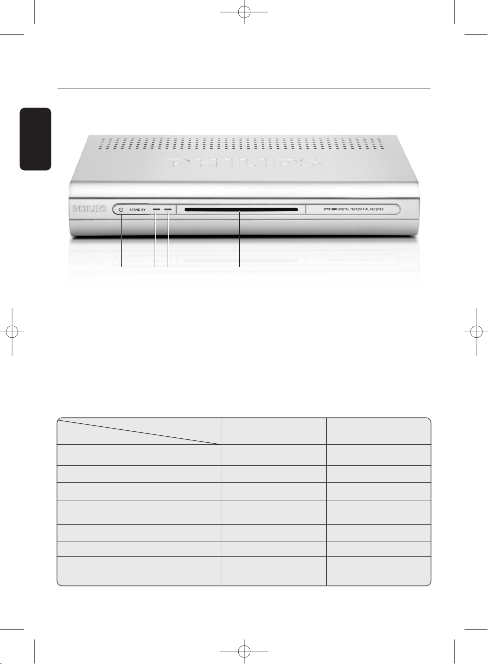
1 STANDBY button: . . . . . . . . . . . . . . . . . . . . . . . Switch the receiver ON or to standby.
2 LED1 (Red): . . . . . . . . . . . . . . . . . . . . . . . . . . . . . . . Display receiver status (see status indicator table).
3 LED2 (Green/Orange): . . . . . . . . . . . . . . . . . . . Display receiver status (see status indicator table).
4 Remote control receiver window
Status indicator table
Status indicator table
8 PRODUCT DESCRIPTION
English
2.2 Front view
LED LED1 LED2
Mode (Red) (Green/Orange)
Receiver in Standby ON OFF
Watching TV OFF green
Listening to the radio OFF blinking green/orange
Pressing a remote control button blinking Depending on
current mode
Timer active ON green
Timer active in Standby ON orange
Software download blinking Depending on
current mode
Q W E R
NOTICE DTR 500.qxd 7/09/2004 15:24 Page 8
Page 9
English
PRODUCT DESCRIPTION 9
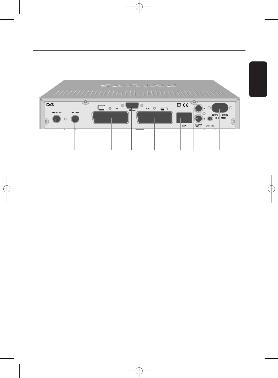
2.3 Rear view
1 AERIAL IN (*): . . . . . . . . . . . . . . . . . . . . . . . . . Input to connect your UHF aerial.
2 RF OUT (*): . . . . . . . . . . . . . . . . . . . . . . . . . . . . RF output to be connected to the aerial input of your
video recorder or TV set,refer to chapter 4 for
recommended connection diagrams.
3 TV(*): . . . . . . . . . . . . . . . . . . . . . . . . . . . . . . . . . . . . SCART (1) socket to connect your TV set or a video
projector (2).
4 SERIAL (*): . . . . . . . . . . . . . . . . . . . . . . . . . . . . . RS232 socket for serial data transfer during servicing.
5 VCR (*): . . . . . . . . . . . . . . . . . . . . . . . . . . . . . . . . SC ART (1) socket to connect your video recorder.
6 LAN: . . . . . . . . . . . . . . . . . . . . . . . . . . . . . . . . . . . . Currently idle.For future use.
7 L/R AUDIO OUT (*): . . . . . . . . . . . . . . . . . . Left/Right analogue audio-cinch outputs to connect your
HiFi/audio receiver system.
8 DIGITAL (*): . . . . . . . . . . . . . . . . . . . . . . . . . . . . Digital audio-cinch output to connect your HiFi/audio
receiver system.
9 230V~50Hz 15W max (**): . . . . . . . . . . Socket to connect the mains cord.
The label showing the type and serial number is underneath the receiver.
(
1) SCART is also called Euroconnector or Peritel.
(2) To connect a video projector to the TV SC ART socket refer to paragraph 4.3.
* Safety Extra Low Voltage
** Hazardous Voltage
WO
T
Q E R U I
Y
NOTICE DTR 500.qxd 7/09/2004 15:24 Page 9
Page 10
10 REMOTE CONTROL
English
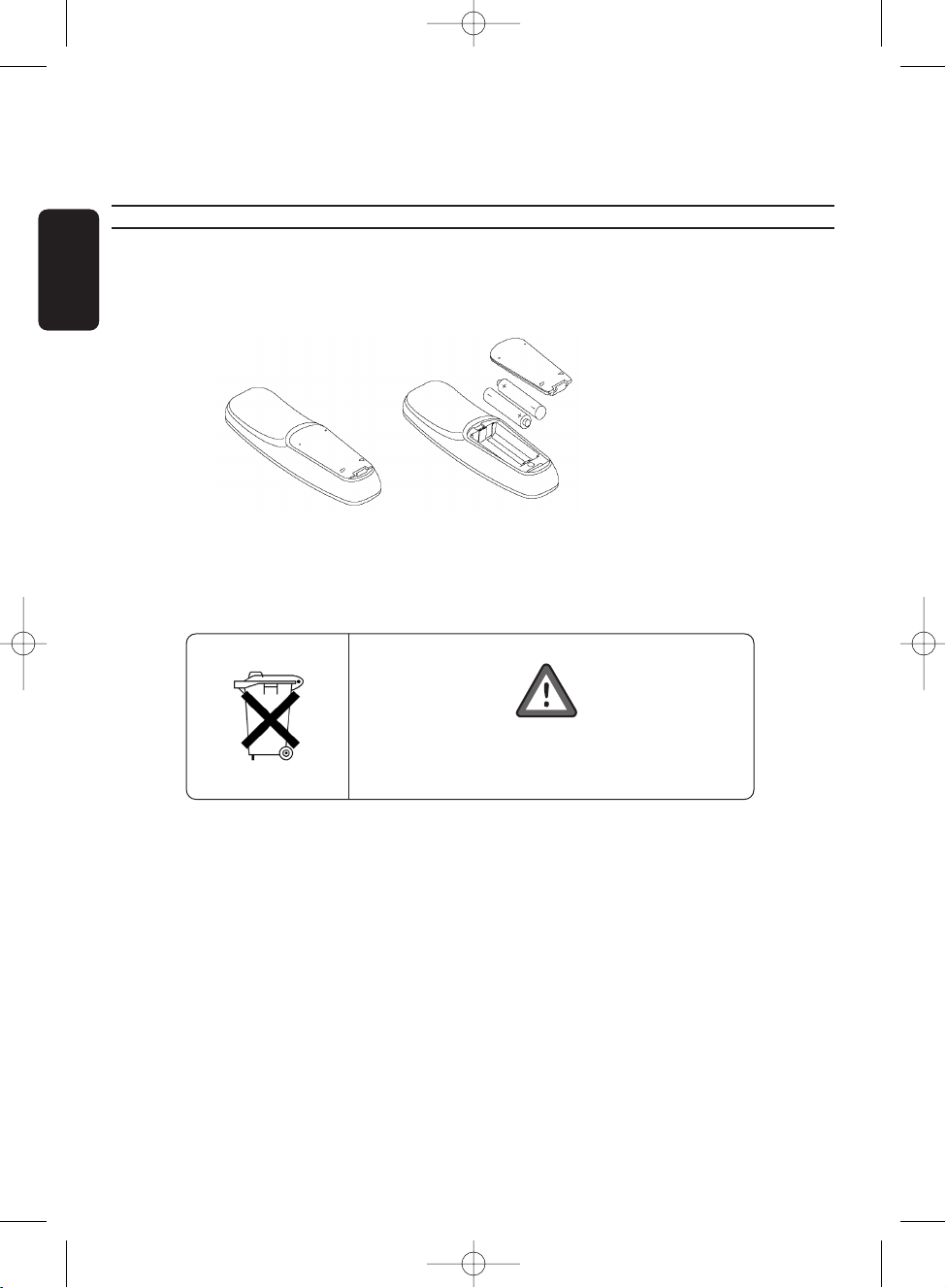
3 Remote control
3.1 Installing the batteries
- Remove the back cover
- Insert two batteries (type R06G/AA -
1.5 V) supplied.
- Position them as shown in the diagram situated in the remote battery compartment.
- Replace the cover.
- Your remote is now ready to control your digital terrestrial receiver.
Note: batteries are removable from the remote control with common household tools (e.g. screwdriver).
Do not dispose of the batteries
with your household waste.
NOTICE DTR 500.qxd 7/09/2004 15:24 Page 10
Page 11

English
REMOTE CONTROL 11
3.2 Using the remote control
Standby
- Standby / ON
TV / RADIO
- T oggle between
TV and Radio mode
P+ / P-
- Next/Previous channel in
digital TV/Radio mode
- Page up/Page down in service
lists
0-9
- Channel selection in digital
TV mode.
GUIDE
- Open Electronic Programme
Guide
INFO
- Open info banner.
- Then show extended
program information
- Then close banner
TIMER
- Access Timer list/Create
timers
The
“TIMER, 0” sequence
keystroke deletes the current
running timer.
BACK
- Recall previously selected
service
- Bring selection one level up
in menu
Mute
- Audio mute
TV / STB
-Toggle between digital TV from
your receiver or analogue
transmission from your TV.
RED, GREEN,
YELLOW, BLUE
- Action depending on context
FAV
- Display available favourite lists
SUBTITLE
- Display available subtitle
languages
I-II
- Display the available audio
languages
WHITE
- inactive
MENU
- Open menu in digital TV running mode
- Close menu in Menu mode
CURSOR t/
y
- Previous/Next channel
- Scroll up/down in menu/lists
CURSOR
i
- Scroll right
- Open one menu level down
CURSOR
u
- Scroll left
- Bring selection one menu level up,or
store option value and bring selection
on left menu side in menu mode
OK
- Display channel lists
- Select service from channel list or EPG
- Confirm and bring selection one menu
level down
VOLUME +/ -
- Volume up / down.
NOTICE DTR 500.qxd 7/09/2004 15:24 Page 11
Page 12

English
4 Connecting your digital receiver
There are several ways you can connect and incorporate your digital receiver into your existing
audio / video equipment set up.
Warning!
Before starting to connect:
- Unplug all equipment (TV set,VCR and/or DVD,etc.) from the mains.
- Do not connect your digital receiver to mains supply now.
- Check your current wiring:you may not need to modify your existing Audio / Video set up
connections if they already match the connection diagrams below.
- Depending on your exiting set up,choose the best suited connection method for incorporating
your digital receiver into your existing Audio / Video set up. Please read chapters 4.
1 and 4.2.
Note: when adding new equipment, be sure to refer to the related installation instructions of the relevant
manual.
4.1 Connecting to a TV and a VCR both fitted with one SCART
socket
Incorporate your receiver in your existing installation as shown on the diagram or follow the
instructions below.
PHILIPS
12 CONNECTING YOUR DIGITAL RECEIVER
NOTICE DTR 500.qxd 7/09/2004 15:24 Page 12
Terrestrial Receiver
RF Cable
TV set
VCR/DVD
PHILIPS
EXT 1EXT 2
For optimum configuration
EXT 1
EXT 2
to AC outlet
ANT IN
ANT OUT
Page 13

English
- Plug your aerial lead plug into the “AERIAL IN” socket of your digital receiver.
- Connect the “RF OUT” socket of your digital receiver to the “ANT IN” socket of your VCR by
means of the RF coaxial lead supplied with your digital receiver.
- Connect the “ANT OUT” socket of your VCR to the aerial input socket of your TV by means of a
RF coaxial lead.
- Connect the “TV” SC ART socket of your digital receiver to the “EXT
1” SCART socket of your TV
by means of the SCART lead supplied with your digital receiver.
- Connect the “VCR” SC ART socket of your digital receiver to the “EXT2” SCART socket of your
VCR by means of a SCART lead.
- Plug all your equipment,excluding your digital receiver, into the mains.
- Switch on your TV and select a channel.
- Plug your digital receiver into the mains.Your digital receiver will display the WELCOME screen
(the green LED will be illuminated).
- Read on chapter 5 to proceed with the channel scan of your digital receiver.
Note:
1- If you have a S-Video VCR refer to paragraph 7.2.3.2 for further settings and consult the user manual of
your VCR.
2- With this connection set up you can:
- Watch digital TV while you record analogue TV.
- Watch analogue TV while you record digital TV.
- Record the digital TV channel you are watching.
- Watch Play Back from your VCR.
CONNECTING YOUR DIGITAL RECEIVER 13
NOTICE DTR 500.qxd 7/09/2004 15:24 Page 13
Page 14

English
4.2 Connecting to your HiFi/Audio receiver equipment.
(Analogue/Digital)
Depending on your HiFi / Audio receiver equipment,you might have several options to connect your
digital receiver.
Analogue connection (A)
Connect the L/R audio output sockets to the relevant L/R audio input sockets of your audio
equipment by means of a double CINCH cable (not supplied).Consult the user manual of your
HiFi/Audio receiver equipment to choose the proper analogue audio inputs.
Note: with this connection set up you can control the audio volume up/down and mute with the remote
control of your digital receiver and alternatively with your HiFi's remote control.
Digital connection (B)
Connect the audio “DIGITAL” output socket to the relevant digital audio input socket of your audio
equipment by means of a single CINCH cable (not supplied).Consult the user manual of your
HiFi/Audio receiver equipment to choose the proper digital audio input.
Note: with this connection set up you can only control the audio volume up/down and mute with your
HiFi / Audio Receiver remote control, refer to the relevant user manual.
4.3 Connecting to a video projector
- Connect the “TV” SCART socket of your digital receiver to your video projector.
Often a video projector is fed with S-Video format video signal.If this is the case with your video
projector, follow the instructions below for connection and installation:
- Connect a SCART/S-Video adapter to the “TV” SC ART of your receiver (not supplied), and
connect the adapter to the S-Video input of your video projector by means of a S-Video cable.
- Refer to paragraph 7.2.3.
1 to change the TV “Video Output” setting of your digital receiver to Y/C .
14 CONNECTING YOUR DIGITAL RECEIVER
NOTICE DTR 500.qxd 7/09/2004 15:24 Page 14
Terrestrial Receiver
to AC outlet
AB
Audio equipment
Analogue
input
AUDIO
LR
Digital
input
Page 15

English
Requirements for fast and successful first installation are as
follows:
• You already have an aerial.
• Your aerial is correctly pointed at the terrestrial
transmitter corresponding to your area (
1).
• Your digital receiver connection is according to the
diagram depicted in chapter 4.
1 or 4.2.
• Your TV set is switched on.
- Connect your receiver to the mains.The receiver front
display gets on and the welcome screen appears.
- Press <OK> to proceed.The Setup screen appears.
5.1 Channel scan
The Setup screen appears.The selection is on Ser vice scan.
- Press <OK> to start scanning for channels.
- Alternatively,press
t to scroll up to the setup option you
want to modify,and then press
i to access the option
values.
The following information is reported on screen:
- scanning progress,
- number of channels found.
When scanning is successfully completed,a completion
message is displayed.
- Press <OK>. A warning message is displayed.
- Press <OK> again to start watching TV.
To know more about using your digital receiver consult
chapter 6.
If scanning failed,proceed with chapter 5.2.
FIRST INSTALLATION 15
5 First installation
NOTICE DTR 500.qxd 7/09/2004 15:24 Page 15
Page 16

English
5.2 Scanning failure
No channels could be found. A scan failure message is
displayed.
Before starting a new scan
It is recommended to perform the following checks:
- connections to your receiver (see chapter 4),
- signal quality (see paragraph 7.3.3),
- antenna installation,
- channel(s) available in the region corresponding to your
area (
1).
The scan failure message is displayed.
- Press <OK> to exit this screen and access the main menu.
- Proceed with installation as described in paragraph 7.3.2.
Note: if the same failure message appears after a while, refer to
chapter
10.
(1) To check whether you can receive digital television in
your region,consult web site WWW.FREEVIEW.CO.UK:
type in your postcode and click on <GO> to
immediately get the answer.
5.3 Repeated scanning failure
No channels could be found,even after checking the signal
quality delivered by your aerial.
Either your aerial is not pointing properly at the digital TV
transmitter, or your aerial installation needs to be upgraded,
or you are not in the coverage area to correctly receive
digital television.Please refer to the Troubleshooting guide at
the end of this user manual.
For a proper diagnosis,call your electrical retailer.
16
FIRST INSTALLATION
NOTICE DTR 500.qxd 7/09/2004 15:24 Page 16
Page 17

6.1 Switch your receiver ON/OFF
(standby)
Your receiver is in standby mode (the red LED is on).
To wake up your receiver:
- Press one of the following remote control buttons:<P+>,
<P>,<OK> or a number button.
- Alternatively,press the <Standby> button on the front
panel.
You are watching digital TV (the green LED is on) or
listening to digital radio (the green/orange LED is blinking).
To put your receiver in standby:
- Press the remote standby button.
- Alternatively,press the <Standby> button on the front
panel.
Your receiver, as any electronic equipment,is
power consuming.In order to reduce power
consumption,please switch your receiver to
standby whenever you are not using it.- For saving energy
compared to the stand by mode,if you are not using your
receiver for a longer period of time,we recommend to
switch off the receiver by unplugging it from the mains.
6.2 Select TV/Radio mode
Your receiver is in TV mode.
To switch to RADIO mode:
- Press the <TV/RADIO> button.
Your receiver is in radio mode
To switch to TV mode:
- Press the <TV/RADIO> button.
English
DAY TO DAY OPERATION 17
6 Day to day operation
NOTICE DTR 500.qxd 7/09/2004 15:24 Page 17
Page 18

English
18 DAY TO DAY OPERATION
6.3 Change channel
6.3.1 Using number buttons
You are watching digital TV or listening to a digital radio
programme:
- Press number button(s) to select the desired channel
number
6.3.2 Using <P+>/<P->
You are watching digital TV or listening to a digital radio
programme:
- Press <P+> to select the next channel in the list.
- Press <P-> to select the previous channel in the list.
6.3.3 Using <BACK> (last channel recall)
You are watching digital TV or listening to a digital radio
programme:
- Press the <BACK> button to return to the previously
selected channel.
6.3.4 Using the channel list
You are watching digital TV or listening to a digital radio
programme:
- Press the <OK> button to open the channel list.
- Press the
t or y button to move to the desired channel.
- Press <OK> to view the selected channel.
6.3.5 Using your favourite lists
You are watching digital TV or listening to a digital radio
programme:
- Press the <FAV> button to open the list of all available
channel lists.
- Press the
y or t to move to the desired list.
- Press the <OK> button to make the list active and tune
your receiver to the first channel in the list
- Press <FAV> again to close the list of all available channel
lists.
Note: empty favourite lists are not displayed.
NOTICE DTR 500.qxd 7/09/2004 15:24 Page 18
Page 19

6.4 Channel banner
Each time you select a new channel,a banner appears at the
top of the screen,indicating:
• Current channel number and name,
• Start and end time of the current programme,
• Current programme name,
• Icons for current channel properties (see table below),
• Current time,
• Time left before next programme start.
The banner displays information about the current
programme (or “NOW” programme).
- Press the
i button to display information on the “NEXT”
programme.Press the
u button to return to the “NOW”
programme view.
- Press the
y button to display information on the next
channel current programme.
- Press the
t button to display information on the previous
channel current programme.
- In any case,press <INFO> to display extended
information on the current selection.
Alternatively:
Press <INFO> once to display the channel banner at any
time.
Then press <INFO> again to display extended information.
And then press <INFO> again to close the channel banner.
6.5 Volume control - / + /
You are watching digital TV or listening to a digital radio
programme:
- Press < -> to decrease volume.
- Press < +> to increase volume.
- Press < > to mute the sound,and press < > again to
de-mute.
Note: change of volume is signalled with a bar graph, while audio
mute is signalled with an icon on the top right corner of the
screen.
English
DAY TO DAY OPERATION 19
icon description
MHEG application
available
Information available
Subtitles available
Alternate audio
languages available
Low battery
Favourite list
NOTICE DTR 500.qxd 7/09/2004 15:24 Page 19
Page 20

English
6.6 Change temporarily the Subtitle
selection (circular toggle)
- Press the < > button.
- Press the
y or t to move to the desired subtitle language.
- Press <OK> to confirm your selection.Alternatively,select
None to disable subtitling.
6.7 Change temporarily the Audio
language selection (circular toggle)
- Press the <I/II> button.
- Press the
y or t to move to the desired audio language.
- Press <OK> to confirm your selection.
6.8 Electronic Programme Guide
You are watching digital TV or listening to a digital radio
programme:
- Press the <GUIDE> button to open the programme guide.
The current programme list (called “Now/Next”) appears.
- Press the
ibutton to consult the current day programme list.
- Press the
y or t to move to the wanted channel.
- Press the <OK> button to select the channel.
6.9 Timers
6.9.1 Setting a timer when watching digital TV
- Press the <TIMER> button to access the timer list.
- Then proceed as described in paragraph 7.5.
1.
6.9.2 Set a timer from the Guide
- Scroll to the programme for which you want to set a
timer.
- Press the red colour button or the <TIMER> button to
set a timer.The timer screen is displayed.
- Modify the timer settings as appropriate.For instance, to set a
reminder, select Remind as Type of timer (default is Record).
- Press the red colour button again to store the timer and
return to the Guide.
20 DAY TO DAY OPERATION
NOTICE DTR 500.qxd 7/09/2004 15:24 Page 20
Page 21

English
DAY TO DAY OPERATION 21
6.9.3 Deleting a running timer
A timer is running and you are watching what you are
recording.Recording is signalled by LED
1 lit in red and LED2
lit in green.
- Press key sequence “TIMER,0” to delete the running timer.
A timer is running and your receiver is in standby. Recording
is signalled by LED
1 lit in red and LED2 lit in orange.
- Press key sequence “TIMER, 0” to delete the running timer.
6.10 DIGITAL TEXT – MHEG interactive
television
- Depending on the application,press either the <TEXT>
button (white colour button) or the red colour button to
enable digital teletext.Note that not all channels transmit
interactive television applications at all times.
Note: programmes carrying interactive television are signalled by
the “ ” icon in the banner.
6.11 Using the TV / STB button
This button is used to switch between watching digital
channels via your digital receiver and standard analogue
channels on your TV.
You are watching digital TV.
- Press the TV/STB button to switch to analogue TV from
your TV .
- Press the TV/STB button again to revert to digital TV.
6.12 Watching locked channels
If you have selected a locked channel,you must unlock this
channel to watch it.
When prompted to enter your PIN code:
- Enter your 4-digit PIN code (default is
1234).
You can change the receiver settings to adapt the receiver to
your aerial conditions, Audio/Video set up or other
preferences.
NOTICE DTR 500.qxd 7/09/2004 15:25 Page 21
Page 22

English
22 CHANGE THE SETTINGS OF YOUR RECEIVER
7.1 General information
7.1.1 Basics about menu navigation
- In normal viewing mode,press <MENU> to display the
Main Menu,including the Puck element.
The Puck element is always present when the menu is
displayed.
The Puck contains 5 elements:
- the yellow ball indicating the current selection;
- the
t,y, u and i green cursors, with red arrows
indicating possible navigation directions.
Note: the Puck cursors are transferred to the right-hand side of
the menu window for the adjustment of the setting values.
The up, down, right and left cursors appear at the top,
bottom, left-hand side, and right-hand side of the value
window respectively.
- Press <MENU> to exit any menu screen.
7.1.2 Change setting
The selection is on the first item of the menu.
- Press the
t or y button to scroll up/down to bring the
selection on the wanted menu item.
- Press the
ibutton to display the sub-items corresponding
to the highlighted item.Repeat this step as many times as
necessary to access the desired option.
Note: press <BACK> to get back one level in the menu.
- Then press the t or y button to select the desired
option value.
7.1.3 Cancel/Store changes
You have selected a value for a setting as described above.
- Either press the <BACK> button to cancel changes,or
press the
u button to store the changes.
In both cases,the selection is brought one level up in the
menu.
- When the Menu is on,press the <MENU> button to close it.
7 Change the settings of your receiver
NOTICE DTR 500.qxd 7/09/2004 15:25 Page 22
Page 23

English
CHANGE THE SETTINGS OF YOUR RECEIVER 23
Notes:
- To open a menu item signalled by a locker, you must enter your
PIN code.
- To avoid burning your TV screen on-screen messages/menus are
automatically set off after 30 min.
7.2 Preferences
- Press the <MENU> button to open the main menu.
- Press the
y button to bring the selection onto
Preferences.
- Press the
ibutton to access the Preferences sub-menu.
7.2.1 Language
The selection is on the Language item of the Preferences
sub-menu.This item is used to select your receiver language
settings,including the menu and audio languages.
- Press the
i button to access the language settings.
- Scroll to the setting you want to change.
The corresponding values are displayed on the right-hand
side of the screen.
- Press the
i button to access the setting values.
• Audio
• Subtitles
• Subtitling Mode
• Subtitles for hearing impaired
• Menu
7.2.2 Location
The selection is on the Location item of the Preferences
sub-menu.This item is used to select the countr y where you
operate your receiver and corresponding time zone .
- Press the
i button to access the location settings.
- Scroll to the setting you want to change.
The corresponding values are displayed on the right-hand
side of the screen.
- Press the
i button to access the setting values:
• Country
• Time Zone
NOTICE DTR 500.qxd 7/09/2004 15:25 Page 23
Page 24

English
7.2.3 System settings
The selection is on the System settings item of the
Preferences sub-menu.
- Press the
i button to access the system settings.
Note: if the parental control is active, you must enter your PIN
code to access the relevant sub-items of this menu item.
7.2.3.1 TV
This item is used to select the format of the signal output
for the TV and VCR SCART socket.
- Scroll to the setting you want to change.
The corresponding values are displayed on the right-hand
side of the screen.
- Press the
i button to access the available values:
• Video Output: RGB, CVBS-PAL,CVBS-SECAM, or Y/C.
RGB is the default and recommended setting.
• Audio Output: Stereo or Mono
• Screen format:select the aspect ratio of the video
output that best suits your TV.
Note: it is recommended to use the RGB setting to get the best
quality of the video at the TV screen. If you use a video
projector instead of a TV set, the Y/C setting is recommended
(refer to paragraph 4.3 for connection and installation).
7.2.3.2 VCR
This item is used to select the format of the signal output
for the VCR SCART socket.
- Scroll to the setting you want to change.The
corresponding values are displayed on the right-hand side
of the screen.
- Press the
i button to access the available values:
• Video Output: CVBS-PAL,CVBS-SECAM, or Y/C.
CVBS-PAL is the default and recommended setting.
• Audio Output: Stereo or Mono
• Easy Record:select the control method that suits your
VCR.Refer to paragraph 9.2 and your VCR user
manual.
Note: If you have a S-Video VCR Recorder, select the Y/C setting.
Please consult the user manual of your VCR/Recorder.
24 CHANGE THE SETTINGS OF YOUR RECEIVER
NOTICE DTR 500.qxd 7/09/2004 15:25 Page 24
Page 25

English
CHANGE THE SETTINGS OF YOUR RECEIVER 25
7.2.3.3 Channel Banner
This item is used to select the channel banner display
settings.
- Scroll to the setting you want to change.
The corresponding values are displayed on the right-hand
side of the screen.
- Press the
i button to access the available values:
• Duration
• T ransparency
7.2.3.4 Volume
This item is used to select the volume level at wake-up.
- Press the
i button to access setting value.
- Press
t or y to modify the volume level.
- Press <OK> to confirm.
7.2.3.5 Remote Control
This item is used to set the remote control address.
- Press the
i button to access the available values.
- Move to the address you want to select:039 or 038.
Default address is 039,which makes it possible to control
your receiver using any Philips TV set remote control.
- Press <OK> to confirm your selection.
- Proceed as described in paragraph 9.
1.
Note: if you do not complete the procedure as described in
paragraph 9.1, you will not be able to control your receiver
using your remote control.
7.3 Installation
- Press the <MENU> button to open the main menu.
- Press the
y button to bring the selection onto
Installation.
- Press the
i button to access the Installation sub-menu.
7.3.1 Service lists
This item is used to manage your service lists.
- Press the
i button to access the service list features.
NOTICE DTR 500.qxd 7/09/2004 15:25 Page 25
Page 26

English
7.3.1.1 Rearrange services
This feature is used to install/uninstall services and move
services within the installed services list.
- First scroll to the service you want to
uninstall/install/move.
- Press <OK> to select the service.The service name
appears in the Selected service zone.
To uninstall a service you selected from the installed
services list:
- Press the red colour button.The service is removed from
the installed service list and appears in the uninstalled
services list.
To install a service you selected from the uninstalled
services list:
- Scroll to the position where you want to install the
service.
- Press the green colour button.The service is removed
from the uninstalled service list and appears in the
installed services list.
To move the service you selected within the list:
- Scroll to the position you want to move the service to.
- Press <OK> to confirm.
7.3.1.2 View new TV channels
- This feature is used to view the new channels found while
your receiver is in standby.
- Press
i to view new channels found in the right-hand side
of the screen.
- Scroll to the channel you want to view.The selected
channel current program is displayed.
Note: press <OK> to uninstall the selected channel. Press
<OK> again to cancel uninstallation.
- Press u to exit the screen and return to the Service lists
sub-menu,or press the blue colour button to exit the menu.
7.3.1.3 Listen to new Radio stations
- This feature is used to listen to the new radio stations
found while your receiver is in standby.
- Press
i to listen to new channels found.
26
CHANGE THE SETTINGS OF YOUR RECEIVER
NOTICE DTR 500.qxd 7/09/2004 15:25 Page 26
Page 27

English
CHANGE THE SETTINGS OF YOUR RECEIVER 27
- Scroll to the station you want to listen to.
Note: press <OK> to uninstall the selected station. Press
<OK> again to cancel uninstallation.
- Press u to exit the screen and return to the Service lists
sub-menu,or press the blue colour button to exit the
menu.
7.3.2 Service setup
This item is used to install services.
7.3.2.1 Add new services
This feature is used to install new available services.
- Press
i enable the installation feature.
- Press <OK> to start searching for new services.
Note: to interrupt the search, press <OK>. No services
are stored.
Once the search has been completed,the total number of
services found is displayed on the right-hand side of the
screen.The Puck moves to the Store button.
- Press <OK> to store the new services.
- Alternatively,scroll down to the Discard button and press
<OK> to discard the new services.
Note: before storing/discarding the services found, you may scroll
up to view the search results respectively for
channels/stations/other services.
- Press u to exit the screen and return to the Service
setup sub-menu,or press the blue colour button to exit
the menu.
7.3.2.2 Reinstall all services
This feature is used to reinstall all services,overwriting the
previous service settings.
- Press
i to enable the reinstallation feature.You are then
prompted to confirm you want to reinstall al services.
- Press <OK>,then proceed as described above.
7.3.3 Test reception
This feature is used to help you position your antenna and
check the availability of signals on specific RF channels.
NOTICE DTR 500.qxd 7/09/2004 15:25 Page 27
Page 28

English
The selection is on RF channel.
- Press
i to access the list of RF channels.
- Scroll up or down the list to the RF channel you want to select.
- Press <OK> to view the signal quality and strength for the
selected channel.
- If need be, move your antenna to obtain an adequate
signal. When the signal is good enough, the name of the
corresponding network is displayed.
- Press
i again to return the list of available RF channels
and proceed as described above to check the signal quality
and strength for another RF channel.
Note: if you cannot obtain an adequate signal, refer to the
troubleshooting guide.
- Press u to exit the screen and return to the Service lists
sub-menu,or press the blue colour button to exit the menu.
7.3.4 Restore factory settings
To restore the receiver factory settings:
- Press <OK>.You are then prompted to enter your master
PIN code.
- Enter the master PIN code. For more information on the
master PIN code, refer to the troubleshooting guide.
Note: when restoring the factory settings, you lose all your
favourite list settings.
7.4 Information
- Press the i button to access the System software sub-menu.
System software
This item is used to manage software updates,which are
necessary to keep your receiver up-to-date with the
developments in digital television and make new features
available.Updates are part of normal transmissions.
Your receiver is originally set up to automatically accept
software updates (recommended).If you want to be
prompted each time new software is available , follow the
instructions below.
- Press the
i button to access the System software settings.
The current hardware/software version is displayed, and the
selection is on Always accept new software.
28 CHANGE THE SETTINGS OF YOUR RECEIVER
NOTICE DTR 500.qxd 7/09/2004 15:25 Page 28
Page 29

English
CHANGE THE SETTINGS OF YOUR RECEIVER 29
- Move the Puck to No if you want to be prompted when
new software is available.
- Press <OK> to confirm.
- Press
u to exit the screen and return to the System
software item,or press the blue colour button to exit the
menu.
Note: to carr y out the update when new software is available,
simply follow the on-screen instructions.
7.5 Timers
- Press the i button to access the Timers sub-menu.
7.5.1 Record/Remind
This item is used to set and edit recording timers and
reminders.
- Press <OK> to access the timer list.
To set a new timer:
Press the green colour button to access the timer settings.
- Scroll to the setting you want to change.
- Press the
i button to access the setting values:
• Type of timer
• Service
• Enter your pin code if locked:PIN code is required
when channels to be recorded are locked (move
Parental Control from On to Off to enable recording
of the selected channel).
• Day & Month
• Start time
• End time
• Audio language
• Subtitle language
• Subtitles for hearing impaired
• Occurrence:Once , Daily,Weekly
- Press the red colour button to store the timer.
- Press <OK> to proceed.The timer list is displayed,
including the new timer.
- Press the yellow colour button to exit the screen and
return to the Timers sub-menu,or press the blue colour
button to exit the menu.
NOTICE DTR 500.qxd 7/09/2004 15:25 Page 29
Page 30

30 CHANGE THE SETTINGS OF YOUR RECEIVER
English
To edit an existing timer:
- Scroll within the timer list to the timer you want to
modify.
- Press the
i button to access the setting values.
- Modify the setting values as appropriate (see above for
details).
- Press the red colour button to store the timer.
A message appears,prompting you to program your VCR.
- Press <OK> to proceed.The timer list is displayed,
including the modified timer.
- Press the yellow colour button to exit the screen and
return to the Timers sub-menu,or press the blue colour
button to exit the menu.
To delete an existing timer:
- Scroll to the timer you want to delete.
- Press the red colour button to delete the timer.The timer
is removed from the list.
Note: deletion is immediate!
- Press the yellow colour button to exit the screen and
return to the Timers sub-menu,or press the blue colour
button to exit the menu.
Note: when a recording timer is running, you cannot zap through
digital channels, but you can switch to analogue TV using the
<TV/STB> button and zap through analogue channels.
To cancel a running timer:
Refer to paragraph 6.9.
7.5.2 Sleep
This item is used to manage recording timers and reminders.
- Press the
i button to access the sleep timer values.
- Scroll to the value you want to select:from 0 to 4 hours
in steps of 30 minutes.
- Press <OK> to confirm the sleep timer value.
- Press
u to exit the screen and return to the main menu,
or press the blue colour button to exit the menu.
7.6 Favourites
- Press the i button to access the Favourites sub-menu.
NOTICE DTR 500.qxd 7/09/2004 15:25 Page 30
Page 31

English
CHANGE THE SETTINGS OF YOUR RECEIVER 31
7.6.1 TV Channels
This item is used to create and edit TV favourite lists.
- Press the
i button to access the favourite list settings
- Scroll to the list you want to create or edit.
- Press the
i button to access the setting values:
• Name:you may change the list name using
u or i to
select the character to be edited,and
t or y to scroll
through the available characters
• Active: select Yes to enable the selected favourite list
• Select TV channels: scroll to the channels, and press
<OK> to add them to the selected list
• Add all ser vices: press <OK> to add all services
• Remove all services:press <OK> to remove all services
- Press
u to exit the screen and return to the main menu,
or press the blue colour button to exit the menu.
7.6.2 Radio Stations
This item is used to create and edit radio favourite lists.
- If need be, press the <TV/RADIO> button to switch to
radio mode.
- Proceed as indicated above.
7.7 Access Restrictions
This item is used to enable and edit access restrictions.
- Press the
i button to access the Access restrictions
setting values:
• Set PIN code protection:select On to enable access
restrictions.
Note: if Set PIN code protection is set to No, you cannot set
the other access restriction settings.
• Maturity rating:select a maturity rating to enable PIN
code protection for programmes which maturity rating
is higher.Alternatively,select None to disable this option.
• TV channels: scroll through the list and press <OK> to
lock access to a channel.
• Radio stations:scroll through the list and press <OK>
to lock access to a station.
• Parental Timers:press <OK> to view existing timers.
Then proceed as described for other timer types to set
or edit parental timers (see paragraph 7.5.
1).
• Change PIN code:press
i to enable the PIN code
change features,then enter your current and new PIN
code as prompted,and then press <OK> to confirm.
- Press the blue colour button to exit.
NOTICE DTR 500.qxd 7/09/2004 15:25 Page 31
Page 32

8 Menu tree
Timers
Favourites
Preferences
Information
Record / Remind
Sleep
TV Channels
Radio Stations
Language
Location
System settings
System Software
List 1 to 4
List 1 to 4
Audio
Subtitle/Teletext
Subtitling Mode
Subtitles for hearing
impaired
Menu
Country
Time Zone
TV
VCR
Digital Audio Output
Channel Banner
Volume
Remote Control
Current Software Version
Always Accept New
Software
Name
Active
Select TV channels
Add all services
Remove all services
Name
Select Radio stations
Add all services
Remove all services
Video Output
Audio Output
Screen Format
Video Output
Audio Output
Easy Record
Duration
Transparency
32 MENU TREE
English
NOTICE DTR 500.qxd 7/09/2004 15:25 Page 32
Page 33

English
MENU TREE 33
Access restrictions
Installation
Set PIN code
protection
Maturity Rating
TV channels
Radio stations
Parental Timers
Change PIN code
Service Lists
Service setup
Test reception
Restore factory
settings
Enter system PIN code
Enter new system PIN code
Re-enter new system pin
code
Rearrange services
View new TV channels
Listen to new Radio
stations
Add new services
Reinstall all services
Network name
Signal quality
Signal strength
RF Channel
Search
TV channels found
Radio stations found
Other services found
Store
Discard
Search
TV channels found
Radio stations found
Other services found
Store
Discard
NOTICE DTR 500.qxd 7/09/2004 15:25 Page 33
Page 34

34 ADVANCED SETTINGS
English
9.1 Changing the remote control setting
If you have other items of equipment in your home and the remote control of the Philips receiver
interferes with them,you can change the setting of the remote control. For this you must change the
setting of both your receiver and remote control.
To change the setting of your receiver:
Refer to paragraph 7.2.3.5.
To change the setting of your remote control:
- Press number buttons
1 and 3 simultaneously and hold them for at least 3 seconds
- Release the two buttons simultaneously.
- Enter the new setting according to remote control setting value set for your receiver within the
next 60 seconds:
• 4 for alternative setting (38)
• 3 for the default factory setting (39)
Note: if the batteries are removed while a button is being pressed, the default setting (39) is restored.
9.2 More about recording
9.2.1 Connecting for Prepare Record or Record Link
This connection allows automatic recording without the necessity for programming your VCR. Prior
to deciding on this connection method:
- Consult the user manual of your VCR to check if and how the “Easy Recording” feature is
supported. Most Philips VCR and DVD+RW recorders support one of the two Easy recording
options.
- Verify that both your TV and VCR have two SCART sockets.
Incorporate your receiver in your existing installation:
- Plug your aerial lead plug into the “AERIAL IN” socket of your digital receiver.
- Connect the “RF OUT” socket of your digital receiver to the “ANT IN” socket of your VCR by
means of the RF coaxial lead supplied with your digital receiver.
- Connect the “ANT OUT” socket of your VCR to the aerial input socket of your TV by means of a
RF coaxial lead.
- Connect the “TV” SC ART socket of your digital receiver to the “EXT
1” SCART socket of your TV
by means of the SCART lead supplied with your digital receiver.
- Connect the “VCR” SC ART socket of your digital receiver to the “EXT2” SCART socket of your
VCR (sometimes called “IN”) by means of a SC ART lead.
- Connect the “EXT
1” SCART socket of your VCR (sometimes called “OUT”) to the “EXT2”
SCART socket of your TV by means of a SCART lead.
- Plug all your equipment,except your digital receiver, into the mains.
- Switch on your TV and select a channel.
- Plug your digital receiver into the mains.Your digital receiver will display the WELCOME screen.
9 Advanced settings
NOTICE DTR 500.qxd 7/09/2004 15:25 Page 34
Page 35

English
ADVANCED SETTINGS 35
- Read on chapter 5 to proceed with the channel scan if not already done.
Note:
With this connection set up:
- You can watch digital TV while you record analogue TV.
- You can watch analogue TV while you record digital TV.
- You can record the digital TV channel you are watching without programming your VCR.
- You can watch Play Back from your VCR
9.2.2 Digital receiver and VCR settings
Refer to paragraph 7.2.3.2 on how to enable the “Easy Recording” function of your digital receiver.
- Depending on your VCR brand and type , you have to set the “VCR control” option to “Prepare
Record” or “Record Link”. Refer to the user manual of your VCR alternatively try the two options
to find out the applicable one.
- Set your VCR to the mode allowing control by your digital receiver.
9.2.3 Recording using the VCR control feature
- Your digital receiver,TV and VCR are connected and set according to 9.2.1.
- You have programmed a timer on your digital receiver.
- At timer star t, your VCR starts recording and at timer end your VCR stop recording under the
control of your digital receiver.You no longer need VCR programming to record digital TV channels.
Note: some VCRs need to be in standby for the recording to start. Please refer to your VCR user manual.
9.2.4 Errors during recording
Three kinds of error can happen during the recording:
• Lost of input signal
• Lost of Power
• Locked channel
Your Philips receiver can detect those errors during the recording, it will signal you those errors the
next time you will use it by a means of an on-screen alarm.
NOTICE DTR 500.qxd 7/09/2004 15:25 Page 35
Page 36

36 TROUBLESHOOTING GUIDE
English
10 Troubleshooting guide
Experiencing difficulty operating your digital receiver? Check the following points first!
No picture,no sound and no front
panel indication.
No picture,no sound,but the front
panel red LED is on.
No picture,no sound but the front
panel the left hand LED is on.
The remote does not operate.
You cannot find all the channels
you think should be available.
You sometimes see a squared
pattern on the screen,your picture
is “freezing” or a picture showing a
TV with a noisy pattern.
Receiver is not plugged into the
mains.
Your receiver is in Standby mode.
You are viewing standard analogue
television.
The SCART connection to the TV
is faulty or loose.
Your TV has not selected the
correct A V/EXT channel.
A timer is running,the receiver is
locked,the front LEDs are either
Green / Red or Orange / Red
The remote control batteries have
been inserted incorrectly or are
dead.
You are not aiming your remote
control at the receiver.
The signal to your aerial may be
weak.
Your aerial may need adjusting or
your local transmitter may not be
working.
There could be a transmission
problem.
Your aerial may have been moved,
for example by severe weather.
Your aerial connection has become
loose or disconnected.
Check mains connection and press
the Standby button on the front of
the receiver.
Press either <P+> or <P-> button
or any number button to bring the
receiver out of standby.
Press the <TV/STB> button on
your remote.
Check SCART TV connection,
making sure cables are firmly
pushed into the sockets.
Tr y manually selecting the AV/EXT
channel on your TV.
Press the “TIMER” and the “0”
buttons successively to cancel the
TIMER and unlock the receiver.
Check the condition of the
batteries and replace if necessary,
according to instructions earlier in
this manual.
Make sure you aim the remote at
the receiver and not at the TV.
Tr y retuning your receiver,
following the relevant steps in
paragraph 7.3.2.If you are still
missing channels,your aerial may
need adjusting.
Call your local dealer.
This normally is only a temporary
situation and should correct itself.
Check signal quality and if
necessary re-align your aerial.
Check all aerial connections and
make sure they are all firmly
pushed into sockets.
Problem Possible cause Action
NOTICE DTR 500.qxd 7/09/2004 15:25 Page 36
Page 37

English
TROUBLESHOOTING GUIDE 37
Problem Possible cause Action
You cannot select all of the
channels and the P+/- or Arrow
up/down buttons do not always
work.
You cannot access a particular
channel,even using the number
buttons.
You have forgotten your PIN code.
I set the timer but it did not
record what I wanted.
The order of my channels has
changed.
The on-screen displays are not as
sharp as expected.
The picture on some channels
seems to have been stretched or
squashed.
Some channels have been selected
as favourites and the favourites
mode is on.
The parental lock has been
activated on this channel and an
OSD message prompts you for
your PIN code.
The video was set incorrectly.
They have been re-arranged as
described in paragraph 7.3.1.1.
If you have connected using SCART
and you have an RGB-capable TV,
one of the receiver settings could
be wrong.
You have connected the receiver
TV SCART to a SCART socket of
your TV set which is not RGBcapable
The broadcast is probably in
widescreen and the receiver
settings may not be correct.
Use the <FAV> button to select
another Favourite list.Use the All
TV Channel list to see all available
TV channels.
Enter your parental code to access
the channel or unlock the channel.
See paragraph 7.7 for more details.
When prompted for your PIN
code, enter the Master PIN code.
This will allow you to proceed as
well as reset the PIN code to the
default PIN code of the receiver
(default is 1234).
The Master PIN Code is 0711.
Note:Keep this code secret to
prevent your children from using it.
Make sure that your video is set
for the same time as your digital
receiver.
Alternatively use one of the Easy
Recording options to control
automatically your VCR (see
paragraph 9.2)
Refer to this section to change the
order again.
Refer to paragraph 7.2.3.1 and
modify the “Video Output” setting
to RGB.
Check if the TV SCART socket of
the TV is RGB-capable. If not refer
to the user manual of your TV to
change the SCART connection to
your TV .
Check the receiver “Screen
format” option setting,following
the information in paragraph
7.2.3.1.If you have a widescreen
TV, you may also need to check the
settings on your TV.
NOTICE DTR 500.qxd 7/09/2004 15:25 Page 37
Page 38

38 TECHNICAL SPECIFICATIONS
English
Video decoding
- MPEG-2 DVB compliant up to
MP@ ML
- Video bit rate: up to 15 Mbit/sec
- Video format: 4:3
(letter box if source is in 16:9) and 16:9
- Resolution: up to 720x576 pixels
Audio decoding
- MPEG layer I/II
Operation/Features
- Award-winning noise-free reception
- Automatic program installation via
scanning
- Automatic program list update
- Program editing for personalised
installation (delete, add, move)
- Subtitles
- TV & Radio modes
- 3 Fav list for TV programs
- 3 Fav list for Radio programs
- Free to air reception
- 7-days Electronic Program Guide
(EPG)
- Parental lock with PIN code
- Child timer
- Fully remote controlled
- Menu controlled installation and
operation using On Screen Display
- 10 event VCR timers
- Record Failure alarm
- Record header message
- Full range RF-loopthrough
- Software upgrade via over the air
download
- MHEG5 1.06 for basic
interactivity/enhanced TV
Application system resources
Processor clock speed 81 MHz
SDRAM - CPU/Video-Graphics 8/16 MB
Flash memory 4 MB
Terrestrial antenna interface
- RF input: IEC 169-2 female connector
- RF output (bypass): IEC 169-2 male
connector
Reception-Demodulation
- Demodulation type: COFDM 2K / 8K
- Network: MFN/SFN
- Input frequency range:
VHF III & UHF IV/V
- Loop-through frequency range (MHz):
47 - 862 MHz
- UHF Channel 21-69
Connections
TV SCART
Output: CVBS,Controlled audio L/R,
RGB,Slow blanking, Fast blanking,
S-Video (for LCD projector)
VCR SCART
Output:
CVBS,Controlled audio L/R, Y/C
Audio CINCH:
Analogue audio output:L/R
Serial interface: R232
Broadband interface:
10BaseT Ethernet modem for future use
Accessories
- Remote control
Type RC19336001/01 (‘Zappa’)
- SCART cable
- RF coaxial lead
- User manual
- Worldwide Guarantee booklet
- Batteries: 2 x 1.5V type AA/R06
- Mains cord
Miscellaneous
- Temperature range (°C)
Operating +5 to 40
Storage -10 to +70
- Mains: 230 V ~ +/-10%
50 Hz
- Power consumption: 15 W max
- Standby: 6 W max
- Weight: 0.980 kg
Including packaging 1.950 kg
- Dimensions: 258 / 42 / 155
11 Technical specifications
This product is in conformity with the requirements of the 95/47/EC and 2002/21/EC directives.
The product complies with
the following European
council Directives:
- 73/23/EEC
- 93/68/EEC
- 89/336/EEC
NOTICE DTR 500.qxd 8/09/2004 14:35 Page 38
Page 39

English
NOTICE DTR 500.qxd 7/09/2004 15:25 Page 39
Page 40

NOTICE DTR 500.qxd 7/09/2004 15:25 Page 40
 Loading...