

Philips DSATX 220 User Manual

DuraWatt DSATX
220-Watt DC-DC ATX Power Supply
User Manual
Version 1.0
Table of Contents
1. Getting Started ...............................................................................................................................1
1.1. Introduction....................................................................................................................................1
1.2. Product Photo......................................................................................................................... 2
1.3. Block Diagram.........................................................................................................................2
1.4. Included Contents and Optional Accessories............................................................................2
2.1. Recommended Additional Supplies..........................................................................................3
2.2. Recommended Tools...............................................................................................................3
2.3. Connection Overview Diagram.................................................................................................3
2.4. Precautions and Warnings.......................................................................................................3
2.5. Detailed Connection Diagram .................................................................................................. 4
2.6. Bench Testing.........................................................................................................................4
2.7. Quick Installation Steps...........................................................................................................5
3. User Guide......................................................................................................................................5
3.1. Theory of Operation................................................................................................................. 5
3.2. Modes of Operation.................................................................................................................5
3.3. LED Codes .............................................................................................................................6
3.4. Basic Mode Timing Diagram.................................................................................................... 6
3.5. Features Explained.................................................................................................................. 6
4. Serial Port Connectivity..................................................................................................................8
4.1. Serial Port Adapters ................................................................................................................ 8
4.2. Serial Port Overview................................................................................................................8
4.3. Basic Programming Control ..................................................................................................... 8
4.4. Diagnostic Feed ......................................................................................................................8
4.5. Extended Basic Programming Examples..................................................................................9
4.6. Advanced Features ...............................................................................................................10
4.7. Advanced Feature Tables......................................................................................................10
5. Specifications...............................................................................................................................11
5.1. Electrical...............................................................................................................................11
5.2. Mechanical............................................................................................................................11
5.3. Connector Pin Locations........................................................................................................ 12
7. Mpegbox.com Limited Warranty..................................................................................................13
1. Getting Started
1.1. Introduction
Thank you for purchasing a DSATX 220 Watt Automotive Power Supply. Please take some time to read
through this manual before attempting to use this product.
The DSATX is the most advanced DC-DC Automotive Computer Power Supply available. It is capable of
properly powering most Pentium 4 and AMD based computers in a motor vehicle as well as their accessories.
Its advanced microprocessor control enables features such as Startup/Shutdown Sequencing, Low Voltage
DSATX Manual Copyright 2006 Mpegbox.com Page 1 of 13
Battery Protection, and Temperature Protection. Features also include Serial Port Control, Diagnostics, and
Upgradeability. Desktop computer motherboards are typically not designed to work in automotive
environments, the design and engineering that went into the DSATX makes every attempt to compensate for
this. Having purchased a DSATX, you will rest assured that you’ve invested in a flexible product that can grow
and expand with your automotive computing system.
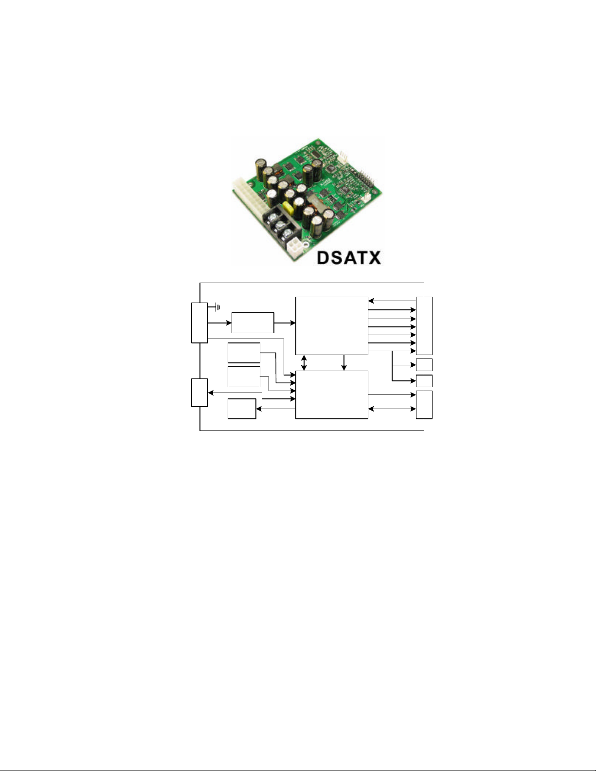
1.2. Product Photo
1.3. Block Diagram
Chassis Ground (GND)
12 Volts In (VIN)
Accessory In (ACC)
Communication Port
(Requires RS-232 or USB
Translator)
J5
J2
Supply
Protection
Temp.
Sensor
Adjust
POTs
Status
LED
DC-DC
Power
Supply
Control Monitoring
Microcontroller
PSON#
PWROK
+5VSB
+5V
+3.3V
-12V
+12V
J7
ATX-20p
J8
ATX-12V
J1
12V FAN
MotherBoard Switch
JP1
Advanced Options
1.4. Included Contents and Optional Accessories
Included:
1 : DSATX 220 Watt Power Supply
1 : 9" 20-pin ATX Power Cable with 2 HDD Power Connectors and 1 Floppy Connector
1 : 12" 4-pin ATX 12V Power Cable (CPU Power Cable)
2 : 0.1" Shunt Jumpers
1 : 24" 2-pin to 2-pin Mother Board Power Switch Cable
3 : Insolated Terminal Ring Crimp/Solder Connectors 12-10AWG
Optional:
• Acroname Serial Port Adapter PN:S13-SERIAL-INT-CONN
• Acroname USB Serial Adapter PN:S19-USB-SERIAL-INT-CONN
• 12” 20-pin ATX Power Cable with 2 HDD Power Connectors and 3 Floppy Connectors
DSATX Manual Copyright 2006 Mpegbox.com Page 2 of 13
2. Installation Guide
2.1. Recommended Additional Supplies
• 12 AWG Hookup Wire for Vin and Gnd Inputs (Minimum Recommended Gauge)
• 12-24 AWG Hookup Wire for Acc Input (Very little current flows through this wire)
• Mounting Screws (4-40 or 6-32)
• Mounting Standoffs (Optional)
• Power Supply Cooling Fan (or assure adequate airflow over the DSATX)
• Custom Enclosure
2.2. Recommended Tools
• Soldering Iron and or Crimp Tool (Secure Input Power Connections)
• Philips Jewelers Screwdrivers (for P1 P2 Adjustment Pots)
• Philips Head Screwdriver (for Mounting Screws and J5 Terminal Screws)
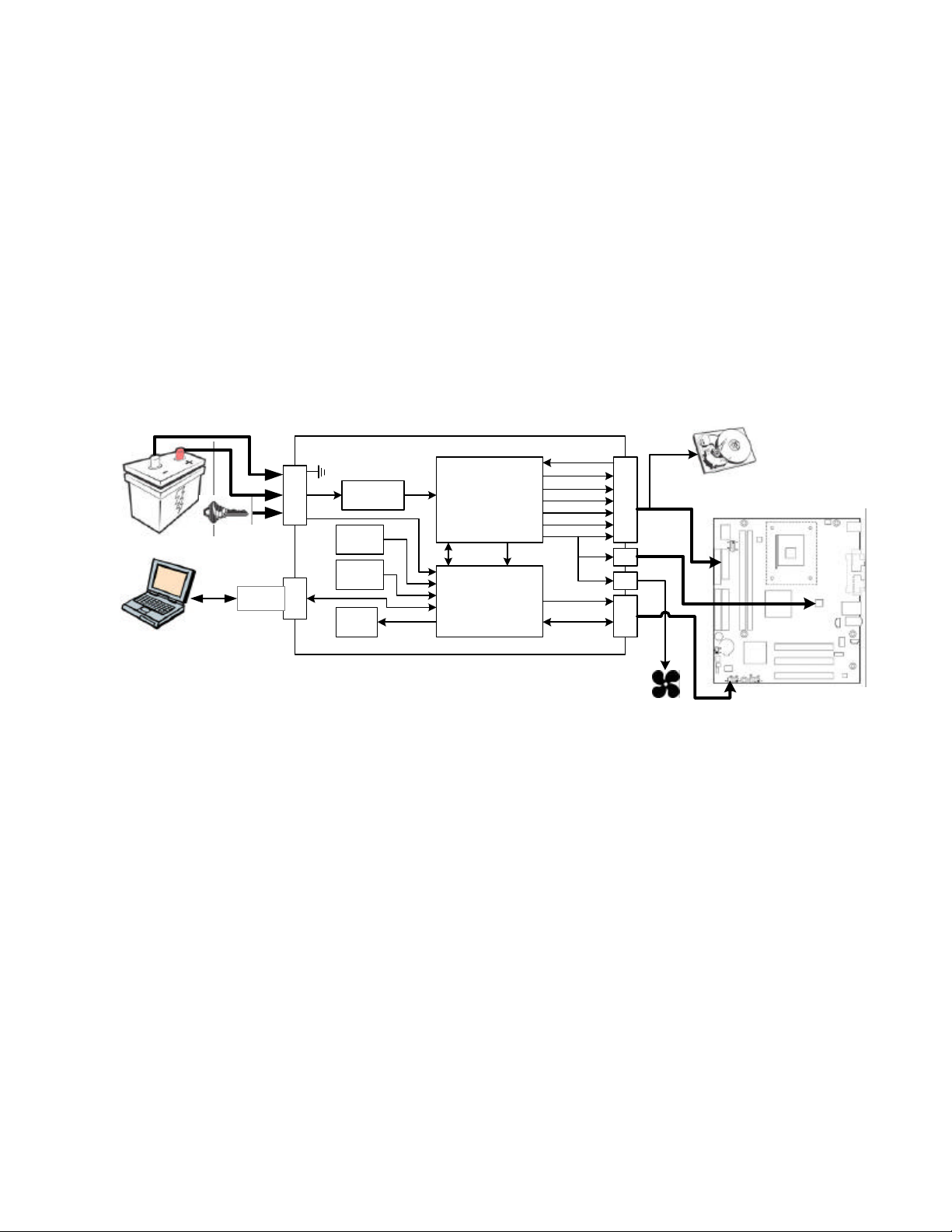
2.3. Connection Overview Diagram
DSATX 220W DC-DC POWER SUPPLY
J5
Translator
Serial Diagnostics
and Control
GND
VIN
ACC
J2
Supply
Protection
Temp.
Sensor
Adjust
POTs
Status
LED
DC-DC
Power
Supply
Control Monitoring
Microcontroller
PSON#
PWROK
+5VSB
+5V
+3.3V
-12V
+12V
Hard Drive
CD-ROM, etc.
ATX
J7
20-pin
P4
4-pin
J8
J1
JP1
Computer
Motherboard
Power
Supply Fan
MB Power Switch
2.4. Precautions and Warnings
Operating a personal computer in a motor vehicle can be dangerous. Improper use or negligence can
result in damage and or loss of life to self and others. Safety precautions must be considered when
operating a personal computer in a motor vehicle. Displays must not be distracting to the driver and should
not display motion video or otherwise distracting content. Check with the local government in your area for
laws and guidelines regarding the use of potentially distracting electronic devices in motor vehicles.
Mpegbox.com and the people responsible for its content shall not be held responsible for loss or damage
as a result of the content, procedures, or the use of the product/s outlined in this manual. A personal
computer used in a motor vehicle should only be operated as a personal computer when then vehicle is
not moving. Use this product at your own risk. Various safety features are built into this product and any
attempt to override them will void any warranties and may cause increased risk of damage to persons or
property.
DSATX Manual Copyright 2006 Mpegbox.com Page 3 of 13
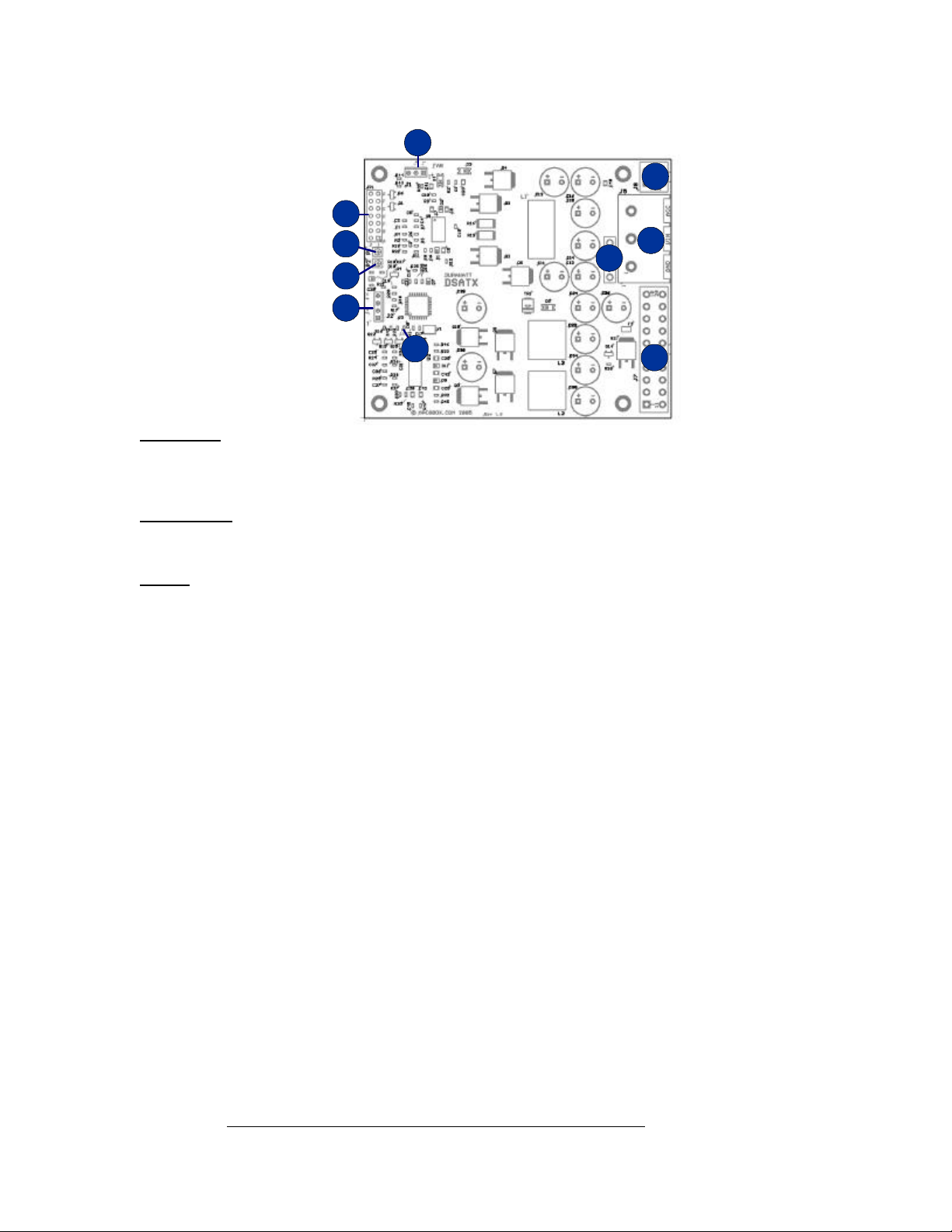
2.5. Detailed Connection Diagram
J1
JP1
J8
P1
P2
J2
D8
J5
F1
J7
Power Input
J5 Gnd: Ground Input, connect to the chassis or the (–) battery terminal
Vin: +12 Volts Input, connect directly to the (+) battery terminal
Acc: Accessory Input, Connect to a switched +12 volt supply wire (ignition or fuse box)
F1 Input Fuse: 20-Amp mini-automotive fuse (yellow)
Power Output
J8 ATX12V: Connect to the 4-pin processor power connector on the motherboard
J7 ATXPWR: Connect to the 20-pin motherboard power connector and peripherals
J1 FAN: Connects to a 12 Volt 3-pin fan to cool the DSATX
Control
JP1 Pins G1, G2: Connects to Motherboard Power Switch Header (G2=Signal Output, G1=Gnd)
P1* Countdown Adj: In Basic Mode, clockwise rotation adds time to the Countdown Timer (0-20m)
P2* Low Voltage Adj: In Basic Mode, clockwise rotation raises the low voltage threshold (10V-12V)
D8 LED indicator: Indicates Operation, Timer States, and Faults
J2 Serial Port: Enables Advanced Modes, field upgrades, and diagnostics
Pins F1, F2: Aux Connection (for Amp Enable or Slave Power Supply)
Pins E1, E2: SL_SEN (RESERVED)
Pins D1, D2: User Switch (will zero countdown timer when shorted)
Pins C1, C2: User1 (RESERVED)
Pins B1, B2: User0 (Shorting Jumper here enables Dumb PSU Mode)
Pins A1, A2: A1=+5V, A2=nReset (RESERVED)
*Note: Do Not Over-Turn P1 and P2, only 270 degrees is available
2.6. Bench Testing
The DSATX can be tested in the lab before being installed into the vehicle. Certain details need to be
noted for proper bench testing. When connecting bench power use between 12 to 16 volts DC to Vin and
Gnd terminals for best results. Small jumper wires may be sufficient to turn on the DSATX alone; however
they will most likely not be adequate to run a computer. For the DSATX to turn on successfully, the bench
supply must be able to provide 2 amps of inrush current. Under full rated load the DSATX draws around
18 amps @ 12V input. 12-volt bench top power supplies capable of delivering this kind of load are
expensive and uncommon. Using 12 gauge or heavier wire will provide the best results. It is OK run a
jumper wire from VIN to ACC for bench testing and certain installations.
To aid in bench testing, a Shorting Jumper at location JP1 pins B1 and B2 will enable Dumb Power Supply
Mode. This will bypass the Startup/Shutdown sequencing and battery protection. ACC is not required and
the LED will indicate that the DSATX is providing power on all the output rails.
The best way to do successful bench testing is to use an adequately sized 12V battery. Bringing in the
battery from the car or using an extra one that has at least a 12-AmpHour capacity will be sufficient in
most cases. Do not connect a Car Battery Charger directly to the DSATX.
DSATX Manual Copyright 2006 Mpegbox.com Page 4 of 13
 Loading...