

Philips DS-9800 Service Manual
Docking Speaker System
DS9800W/10/37/93
Contents Page
1 Technical Specification and Connection Facilities
2 Laser Beam Safety Precautions......................................... 2-1
3 Important Safety Precautions .................................. 3-1 to 3-2
4 Safety Check After Servicing ............................................. 4-1
5 Safety Information General Notes & Lead Free
Requirements .................................................................... 5-1
6 Standard Notes For Servicing,Lead Free Requirements
& Handling Flat Pack IC .......................................... 6-1 to 6-4
7 Direction of Use ....................................................... 7-1 to 7-2
8 Cabinet Disassembly Instructions ........................... 8-1 to 8-2
9 Troubleshooting ................................................................. 9-1
10 Block Diagram .................................................................10-1
11 Wiring Diagram ...............................................................11-1
12 Key-press+MPS Line+LED and Remote incept Board
Circuit Diagram ....................................................12-1
Layout Diagram ...................................................12-1
13 Main Frequency Divider Board
Circuit Diagram ................................................12-2
Layout Diagram ...............................................12-2
©
Copyright 2011 Philips Consumer Electronics B.V. Eindhoven, The Netherlands.
All rights reserved. No part of this publication may be reproduced, stored in a
retrieval system or transmitted, in any form or by any means, electronic,
mechanical, photocopying, or otherwise without the prior permission of Philips.
Published by Sophie-KM 1148 AVM Printed in the Netherlands
.................................................1-1 to 1-7
Contents
14 Deputy Frequency Divider Board
Circuit Diagram .................................................12-3
Layout Diagram.................................................12-3
15 Ipod Board
16 LED and DC Board
17 Power Board
18 Decoder Board
20 Exploded View..............................................................13-1 to 13-2
21 Revision List .....................................................................14-1
Circuit Diagram .................................................12-4
Layout Diagram ................................................12-4
Circuit Diagram .................................................12-5
Layout Diagram ................................................12-5
Circuit Diagram ...............................................12-6
Layout Diagram ..............................................12-7
Circuit Diagram ...............................................12-8
Layout Diagram ..............................................12-9
Feature
Features
RDS
Voltage Selector
ECO Standby
DTS
Subject to modi cation EN
Different
/10 /93
Page
/37
3141 785 36251
Version 1.1
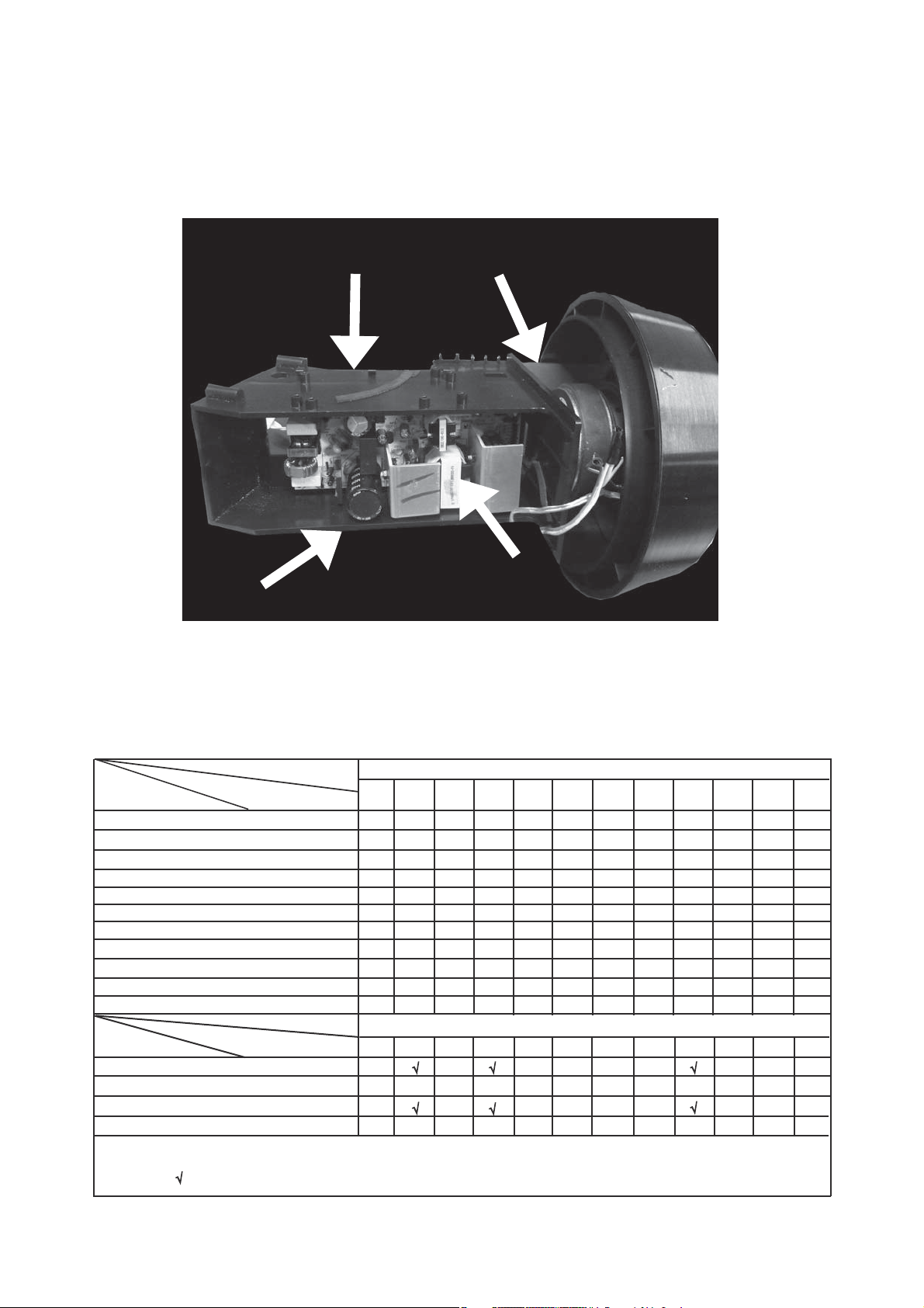
Location of PC Boards
Technical Specification and Connection Facilities
Decoder Board
Main Frequency Divider Board
Remote Incept Board
Power Board
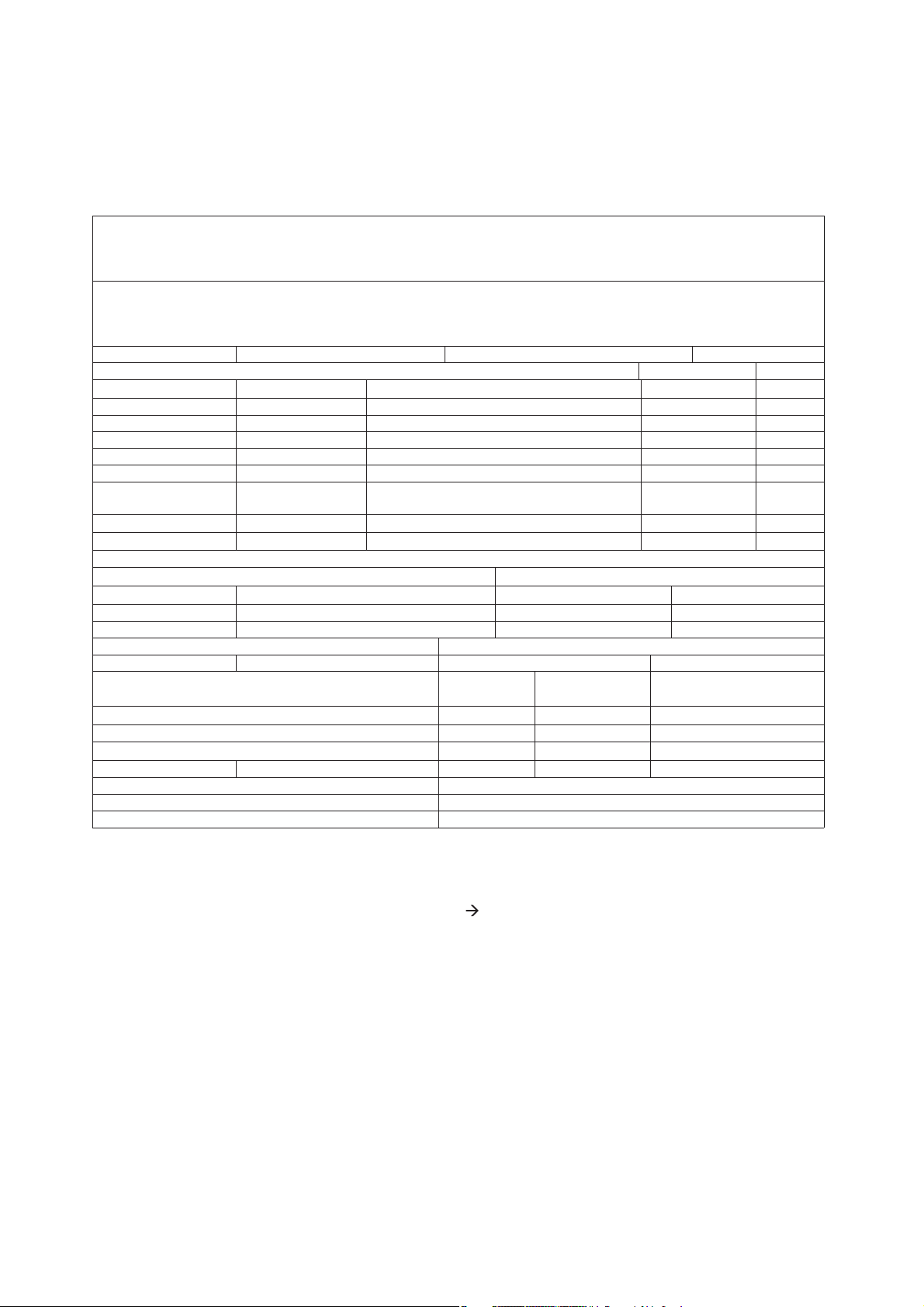
Version Variations
Type /Versions:
Board in used:
Key-Press+MPS Line+LED Board
Remote Incept Board
Main Frequency Divider Board
Power Board
Decoder Board
Deputy Frequency Divider Board
WIFI Board
Ipod Board
LED Board
DC Board
Features
RDS
VOLTAGE SELECTOR
ECO STANDBY - DARK
DTS
* TIPS : C -- Component Lever Repair.
M -- Module Lever Repair
Service policy
Type /Versions
Feature diffrence
-- Used
/05
/05
DS9800W
/55
/58
/61
/79
/93
/94
/37
/12/10
C
C
C
M
M
C
M
C
C
C
C
C
C
M
M
C
M
C
C
C
C
C
C
M
M
C
M
C
C
C
/96
/98
DS9800W
/37
/12/10
/55
/58
/61
/79
/93
/94
/96
/98
1-1
Technical Specification and Connection Facilities
Technical Specification
2. General Information and Requirement
Product Family Features
2.1.1 Identity and Key Features
2.1
DS9800W series are wireless speaker for iPhone,
Elements to include as generic requirements:
1. Detachable mains cord
2. Safety certification (cUL/FCC and CB/EMC/CE)
Following is a list of key features:
1. iPod/iPhone Airplay support
2. MP3 Link (via headphones jack from PC or MP3 player)
3. Total output power
2x50Wrms @10%THD
2.1.2 Styling, Forms and Functions
DS9800W appearances are defined in their respective MUS. MUS is the leading document where product
appearance is applicable..
Features Products DS9800W
Stroke versions
Design
Front
Dimension
Apparatus tray closed
W x D x H (mm)
Weight
Cosmetics
Without packaging 11kg
2.1.3 External I/O Connections
Model DS9800W
Stroke Version All
30pin connector on
docking
MP3 Link
(3.5mm audio jack)
L Speaker out
Refer to MUS[3] for
√
√
√
All
details
Y revieceR RI
mm3 teef fo thgieH
kcalB roloC
snottuB
1-2

Technical Specification and Connection Facilities
2.1.4 ACCESSORIES (tbc)
The product appearances and functions are defined in their respective MUS. Product management
approves the MUS and it is a leading document where product appearance is applicable.
Please refer to Sh560 for mechanical information.
Model
Stroke Version 12
Region
Power Cord
Audio cable
(3.5mm audio)
Speaker cablex1
Remote Control
Battery for Remote
control
Quickly guide
IFU
Mechanical General Information
CR2032 CR2032
DS9800W
10 93
Europe
1.8M 1.8M
0.5M 0.5M
6M 6M
8keys 8keys
1 1
1 1
China
1.8M
0.5M
6M
8keys
CR2032
1
1
Safety Standards
Where applicable:
/12, /05 – EN-60065:2002 (Edition 7.0) +A1 +A11 +C11 +C12, UL-6500:2006 (Edition 2), other strokes IEC-
60065:2005 (Edition 7.1), or
/12, /05 – EN-60950:2006 +A1, /37 – UL-60950 (Edition 2), /55 /79 /97 (other strokes than /12, /05, /37) –
IEC-60950 +A1 (Edition 2)
EMC Requirements
Where applicable:
/12 – Audio functions: EN55013:2001; +A1:2003, +A2:2006, EN55020:2007
IT-functions: EN55022:2006,+A1:2007, EN55024:1998, +A1:2001, +A2:2003
WiFi-function: ETSI EN 300 328 (V1.7.1.), ETSI EN 301 489-1 (V1.8.1.) & -17 (V1.3.2), EN
62311:2008
Generic functions: EN 61000-3-2:2006, EN 61000-3-3:1995; +A1:2001; +A2:
EN61000-3-3:2008
/97 (/55) – Audio functions: CISPR-13:2006 (or alternatively CISPR-13:2009), CISPR-20:2005;
IT-functions: CISPR-22;2008, CISPR-24:1997; +A1:2001, +A2:2002; IEC 62311:2007
Generic functions: IEC 61000-3-2:2005,+A1:2008,+A2:2009 or alternatively IEC 61000-3-2:2009, IEC
61000-3-3:2008
/37 – FCC-15.247 (Part B, C), OET Bulletin 65, Edition 97-01 Table 1; RSS-210 Issue 7
2005 or alternatively
1-3
Technical Specification and Connection Facilities
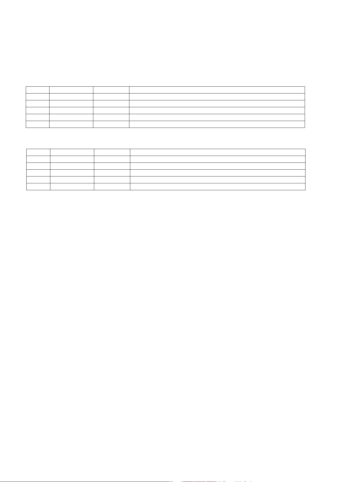
ESD Requirements(TBC)
The product shall withstand electro static discharges on all user accessible parts of the product.
Reference: IEC61000-4-2.
For contact discharges:
Level General (kV) USA (kV) Requirement
1 0-2 0-3 No deviations allowed.
2 >2-4 >3-4 Short perceptible deviations allowed
3 >4-5 >4-5 Normal recallable functions function changes allowed.
4 >5-7 >5-7 Control recallable functions function changes allowed.
5 - >7-8 No loss of stored data allowed.
For air discharge:
Level General (kV) USA (kV) Requirement
1 0-4 0-6 No deviations allowed.
2 >4-8 >6-8 Short perceptible deviations allowed.
3 >8-10 >8-10 Normal recallable functions function changes allowed.
4 >10-15 >10-15 Control recallable functions function changes allowed.
5 - >15-18 No loss of stored data allowed.
General requirement:
1. 10 arcs for positive and negative polarity for unit “on” and “off” for 1kV incremental steps.
2. Component or mechanical damage is not allowed. No loss of fixed stored data (stored in EEPROMs).
3. Hang-ups and malfunctions are allowed, as long as the customer can “recover” from the hang-up by
pressing the Standby or ON/OFF button of the set.
4. Failures that disappear only by unplugging the AC mains cord and/or power sources are not acceptable.
Environmental Condition
The environmental condition requirements and test method is according to UAN-D1590.
Ambient temperature : max. 40 ° C - all climates
Apparatus acc. to spec. : +5 to + 35 ° C
Vibration test (acc. IEC 60 068/2/6) : operational vibration test to be proceeded in operating position of the
set.
1-4
3. Technical Specifications
Technical Specification and Connection Facilities
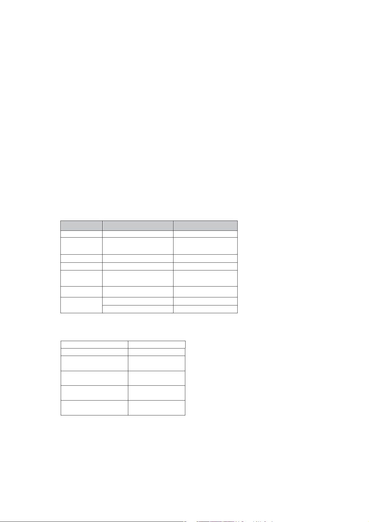
3.1.1 Type and versions
3.1.1.1 SMPS for main unit
Build-inSMPS will be used for all models and stroke versions.
All using figure '8' socket, will cater for all versions:
All requirements per defined for each country should be met with sufficient testing.
Power Supply
Versions Region/Country SMPS Detachable mains cords
1) 100 ~240Vac nom. (wide
37 NAFTA
98 APAC
94 India
range from 90V~264Vac limit)
used in all versions except
India.
Frequency: 47~63Hz.
2) 100 ~310Vac limit (India
compatible with up cost) used
only for India.
Frequency: 47~63Hz.
UL flat pin (non-polarized)
EU round 2-pin
EU (/12) round 2-pin
nip-3 )50/( KU & nip-2 dnuor )21/( UE KU / EPORUE 50 / 21
nip-2 dnuor deifitrec ORTEMNI MATAL 55
3.1.1.2 Adaptor for Docking
AC/DC adaptor 5V/ 2.1A for docking, wide range input voltage.
3.1.2 Surge Immunity (Lightning Test)
The product shall withstand mains interference’s of:
Differential mode:
• 2kV/2 ohm criteria C for Europe.
• 6kV/12 ohm criteria C for NAFTA.
Parameters:
• Bi-wave
• Open circuit voltage: 2/50us
• Short circuit current: 8/20us
• From +/1kV to +/-2kV (for Europe) or +/-6kV (for Nafta) in steps of 1kV.
• 10 shots per combination.
• One shot per minute.
• Serial impedance: 2 Ohm for Europe, 12Ohm for Nafta.
• Polarity and phase: Positive (phase 90º) & Negative (phase 270º)
1-5

Technical Specification and Connection Facilities
Common mode:
• 6kV/2 ohm criteria C for Europe.
• 6kV/12 ohm criteria C for Nafta.
Parameters:
• Ring-wave (100kHz)
• From +/3kV to +/-6kV in steps of 1 kV.
• 10 shots per combination.
• One shot per minute.
• Serial impedance: 2 Ohm for Europe, 12Ohm for Nafta
• Polarity and phase: Positive (phase 90º) & Negative (phase 270º)
Reference: IEC61000-4-5 and for USA: 3135 019 8029 Reliability evaluation.
Requirements:
• Apparatus should fulfil the leakage current requirements of IEC60065 point 9.1.1 (UAN-D1631)
• Defects or permanent deviations are not allowed.
3.1.3 Mains Drop-out Immunity
The product shall withstand mains failures of:
• Variation 0% (=100% dip) at T-event = 50 mSec. Performance criterion B
• Variation 40% (=60% dip) at T-event = 100 mSec. Performance criterion B
• Variation 0% (=100% dip) at T-event = 5 Sec. Performance criterion C
Additional for USA apparatus: See 3135 019 8029 Reliability evaluation.
• Variation 0% (=100% dip) at T-event = 100 mSec in standby mode. Performance criterion B
Requirement:
No misoperation and no interference of user in order to guarantee continuation of performed function.
Reference: IEC61000-4-11 For measuring method refer to UAN-D1724, as far as applicable.
Performance criterions according to IEC61000-4-4 Amendment 1
Performance Requirement
Criterion A - No any degradation of specification.
Criterion B - Temporary degradation / self recoverable.
Criterion C - No damage, resolvable hang-up.
Criterion D - Not recoverable loss of function.
3.1.4 iPod/iPhone/iPad charging
3.1.5 Power Consumption
Power consumption at nominal AC input:
1. CD play mode at 1/8 P-rated output power DS9800W: ≤ 22
2. Low Power Standby Mode : ≤ 0.5
W
W
1-6
Technical Specification and Connection Facilities
D
D
Technical Description
3.2.1 Audio part
traP larenreG
Output Stage Protection: NA Temperature : Yes Short Circuit: Yes
srotacidnI
evitcA yalpsiD kcolC :rotacidnI edoM ybdnatS
ffO snruT DEL :edoM ybdnatS rewoP
Electrical Data
DSC: NA Channel Difference:
DBB: NA Hum (Vol
--- Vol
min
-20dB) 100nW 150nW
max
Bass: Y Residual Noise(Volume Minimum) 40nW
Treble: Y Channel Seperation: 1kHz/10kHz 40dB/35dB
SNR
SNR @standard output(A-
(*1)
@ROP(A-weighted): 90dBA(*3) 92dBA
*2
weighted)(
):
Crostalk:
Audio Inputputs
Audio Input Sensitivity(± 3dB) rated output power at 1kHz
MP3_link(front)
Output Power(*4) At THD=10%, 1kHz sinewave
Output Power with limitation(shipment sample)
Frequency Response(± 3dB)
1000mV± 200mV; Rin ≥ 22kΩ
50W± 1dB
36W± 1dB
30Hz-20kHZ
Audio Output
Loudspeaker(Boxes): Separable speaker box Refer to package document of Speaker Box Assy
Speaker driver Impedance: Right/Left: 8Ω @ 30 Hz ~ 20kHz(-1db)(tbc)
:refoowbuS
REMARKS:
Electrical Parameters are to be measured at Speaker Terminals across rated impedance Load(8ohm) with
Rated Input Signal in CD Mode setting in DBB/Loudness Off and Pre-eq at Flat unless specified otherwise.
*1) Add 10dB to the measured SNR for the final result
as a -10dB reference signal is used (IEC (A)
weighted @ Vol.max with -10dB)
*2) standard output --- 1W output with 1kHz sinewave
*3) SNR value is defined at Airplay mode, at MP3-link mode are worse a little.(SNR @ROP(A-Weighted):
limit 85dBA, @1W output (A-Weighted): limit 78dBA)
*4) Test mode : press RESET and WPS key 5s, the set go to factory mode. Many electrical parameter
should measured at factory mode.
Normal Limit
± 3dB
%8.0< lamixaM,DHT Y :ssenduoL
82dBA
≥55dB
78dBA
cbt yalpriA enohPi
A1.2 tnerruc gnigrahc gnikcoD @5V voltage power supply
W0089SD
( At Cold Condition with 10% TH
( At Cold Condition with 10% TH
1-7
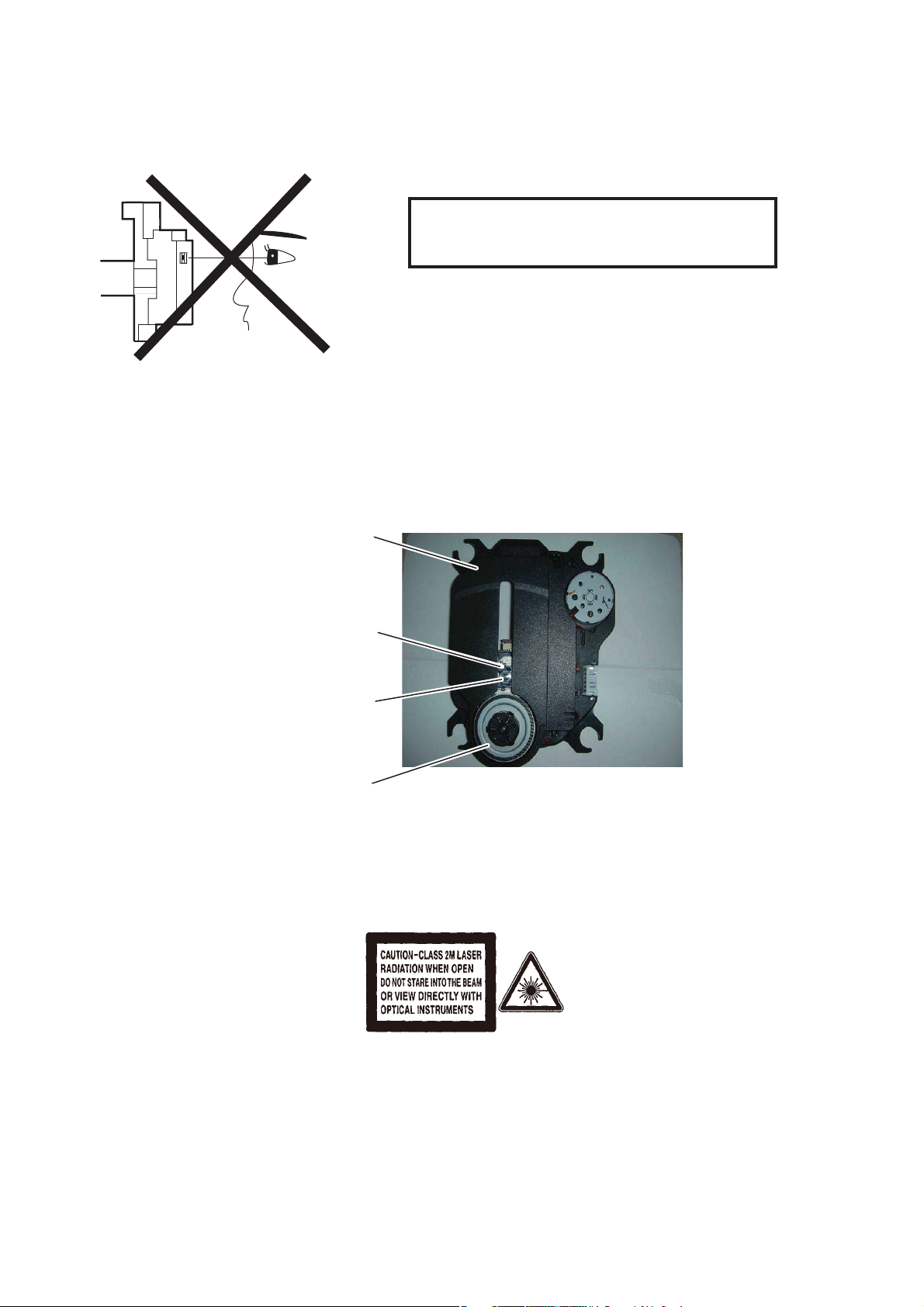
Laser Beam Safety Precautions
This Blu-Ray player uses a pickup that emits a laser beam.
Do not look directly at the laser beam coming
from the pickup or allow it to strike against your
skin.
The laser beam is emitted from the location shown in the figure. When checking the laser diode, be sure to keep
your eyes at least 30 cm away from the pickup lens when the diode is turned on. Do not look directly at the laser
beam.
CAUTION: Use of controls and adjustments, or doing procedures other than those specified herein, may result in
hazardous radiation exposure.
Drive Mechanism Assembly
Laser Beam Radiation
Laser Pickup
Turntable
Location: Inside Top of Blu-Ray mechanism.
2-1

Important Safety Precautions
Caution: These servicing instructions are for use by qualified service personnel only.To reduce the risk
of electric shock do not perform any servicing other than that contained in the operating
instructions unless you are qualified to do so.
Important
Read and understand all instructions before you use
your home theater. If damage is caused by failure to
follow instructions, the warranty does not apply.
Safety
Riskof electricshock or fire!
Never expose the product and
accessories to rain or water. Never place
liquid containers, such as vases, near the
product. If liquids are spilt on or into the
product, disconnect it from the power
outlet immediately. Contact Philips
Consumer Care to have the product
checked before use.
Never place the product and accessories
near naked
including direct sunlight.
Never insert objects into the ventilation
slots
or other openings on the product.
Where the mains plug or an appliance
coupler is used as the disconnect device,
the disconnect device shall remain readily
operable.
Disconnect the product from the power
outlet before lightning storms.
When you disconnect the power cord,
always pull the plug, never the cable.
Riskof short circuit or
Before you connect the product to the
poweroutlet,ensurethatthepower
voltage matches the value printed on the
back or bottom of the product. Never
connec
if the voltage is different.
Risk of injury or damage to the home theater!
For wall-mountable products, use only
the supplied wall mount bracket. Secure
the wall mount to a wall that can support
the combined weight of the product
and the wall mount. Koninklijke Philips
Electronics N.V. bears no responsibility
for improper wall mounting that results in
accident, injury or damage.
ames or other heat sources,
re!
ttheproducttothepoweroutlet
For speakers with stands, use only the
supplied stands. Secure the stands to
the speakers tightly. Place the assembled
stands on flat, level surfaces that can
support the combined weight of the
speaker and stand.
Never place the product or any objects
on power cords or on other electrical
equipment.
If the product is transported in
temperatures below 5°C, unpack the
product and wait u
matches room temperature before
connecting it to the power outlet.
Visible and invisible laser rad
open. Avoid exposure to beam.
Do not touch the disc optical lens inside
the disc compartment.
Risk of overheating!
Never install this product in a confined
space. Always leave a space of at least
four inches around the product for
ventilation. Ensure curtains or other
objects never cover the ventilation slots
on the product.
Risk of contamination!
Do not mix batteries (old and new or
carbon and alkaline,
Remove batteries if they are exhausted
or if the remote control is not to be used
for a long time.
Batteries contain chemical substances,
they should be disposed of properly.
ntil its temperature
iation when
etc.).
Product care
Do not insert any objects other than discs
into the disc compartment.
Do not insert warped or cracked discs
into the disc compartment.
Remove discs from the disc compartment
ifyouarenotusingtheproductforan
extended period of time.
Only use microfiber cloth to clean the
product.
3-1

Important Safety Precautions
Disposal of your old product and
batteries
Your product is designed and manufactured
with high quality materials and components,
which can be recycled and reused.
When this crossed-out wheeled bin symbol
is attached to a product it means that the
product is covered by the European Directive
2002/96/EC.Pleaseinformyourselfaboutthe
local separate collection system for electrical
and electronic products.
Please act according to your local rules and
do not dispose of your old products with your
normal household waste.
Corr
ect disposal of your old product helps to
prevent potential negative consequences for
the environment and human hea
lth.
Your product contains batteries covered by
the European Directive 2006/66/EC, which
cannot be disposed with normal household
waste.
Please inform yourself about the local rules
on separate collection of batteries because
correct disposal helps to prevent negative
consequences for the environmental and
human health.
3-2
 Loading...