

Page 1
12.18.07
Philips Medical Systems
www.medical.philips.com/us
Note for Architects and/or Contractors: "If revisions are listed, these drawings must be thoroughly reviewed so that all changes can be incorporated into your project"
Rev.
Level
Date Revision Descriptions By
Revisions
Table of Contents
Section A - Equipment Plan
General Notes -------------------------------------- AN
Equipment Plan ------------------------------------- A1
Equipment Details ----------------------- AD1 - AD2
Transport Details --------------------------------- AD3
Section S - Support Plan
Support Notes --------------------------------------- SN
Support Plan - Floor and Wall ------------------- S1
Support Plan - Ceiling------------------------------ S2
Support Details --------------------------- SD1 - SD2
Not Site Specific
Digital Diagnost VM
- Standard Reference Drawing -
Date
Quote Number O.A. Number
Drawn By
Section E - Electrical Plan
Electrical Notes ------------------------------------ EN
Electrical Plan -------------------------------- E1 - E2
Electrical Details --------------------------------- ED1
Section N - Network Plan
Network Diagram ---------------------------------- N1
Check List ----------------------------------------- CHK
N-SRD040005
Project Number
C1
Sheet 1 of 17
THE INFORMATION IN THIS PACKAGE IS PROVIDED AS A CUSTOMER CONVENIENCE, AND IS NOT TO BE CONSTRUED AS ARCHITECTURAL DRAWINGS OR CONSTRUCTION DOCUMENTS.
Philips assumes no liability nor offers any warranty for the fitness or adequacy of the premises or the utilities available at the premises in which the equipment is to be installed, used, or stored.
Page 2
HVAC Requirement for General Equipment Locations
Heating, ventilation, air conditioning requirement for general equipment locations must
maintain temperature at 75° +/- 11° fahrenheit (24° +/- 6° celsius) and non-condensing
relative humidity at 47%, +/- 28%.
Electrical Requirements
Optimus 65/80/C
Supply Configuration: 3 phase, 3 wire power and ground. Delta or wye
Nominal Line Voltage: 400, 440, 460 or 480 VAC, 60 Hz
Branch Power Requirement: 150 KVA
Circuit Breaker: 3 pole, 100 Amps (@ 480V)
(03.0)
(06.0)
Minimum Site Preparation Requirements
A smooth efficient installation is vital to Philips and its' customers. Understanding what the
minimum site preparation requirements are will help achieve this goal. The following list clearly
defines the requirements which must be fulfilled before the installation can begin.
1. Walls to be painted or covered, baseboards installed, floors to be tiled and/or covered,
ceiling shall have grid tiles and lighting fixtures installed.
2. Doors and windows, especially radiation protection barriers, installed and finished with
locksets operational.
3. All electrical convenience, conduit, raceway and junction boxes installed.
4. Incoming mains power operational and connected to room x-ray breaker.
5. 115v convenience outlets operational.
6. All support structures correctly installed. All channels, pipes, beams and/or other supporting
devices should be level, parallel, and free of lateral or longitudinal movements.
7. All contractor supplied cables pulled and terminated.
8. A dust-free environment in and around the procedure room.
9. All HVAC (heating, ventilating and air conditioning) installed and operational as per
specifications.
10. Architectural features such as computer floor, wood floor, casework, bulkheads, installed
and finished. When technical cabinets are installed in a closet with doors, it is suggested that
the customer install a temperature alarm in the event of an air conditioning failure.
11. All plumbing installed and finished.
12. Philips does not install or connect developing tanks, automatic processors or associated
equipment, built in illuminators, cassette pass boxes, loading benches and cabinets, lead
protective screens, panels or lead glass window and frame. This is to be done by the
customer/contractor.
13. Clear door openings for moving equipment into the building must be 42" (1067mm) w x 82"
(2083mm) h min. 48" (1219mm) w x 82" (2083mm) h rec., or larger contingent on an 8'-0"
(2438mm) corridor width.
Note
Once Philips has moved equipment into the suite and started the installation, the contractor
shall schedule his work around the Philips installation team on site. It is suggested that a
telephone be provided in the room to receive telephone calls. This would alleviate facility staff
from answering calls for Philips personnel.
Remote Service Diagnostics
Medical imaging equipment to be installed by Philips Medical is equipped with a service
diagnostic feature which allows for remote and on site service diagnostics. To establish this
feature, a dedicated direct-distance - dialing, voice-grade line must be installed as shown on
plan. All costs with this feature are the responsibility of the customer.
(00.1)
General Specifications
1. Responsibility
The customer shall be solely responsible, at its expense for preparation of site, including any
required structural alterations. The site preparation shall be in accordance with plans and
specifications provided by Philips. Compliance with all safety, electrical, and building codes
relevant to the equipment and its installation is the customer's responsibility. Sufficiency of
such plans and specifications, specifically including, but not limited to the accuracy of the
dimensions described therein, shall be the sole responsibility of customer. The customer shall
advise Philips of conditions at or near the site which could adversely affect the carrying out of
the installation work and shall ensure that such conditions are corrected and that the site is fully
prepared and available to Philips before the installation work is due to begin. The customer
shall provide all necessary plumbing, carpentry work, or conduit wiring required to attach and
install products ready for use.
2. Permits
Customer shall obtain all permits and licenses required by federal, state/provincial or local
authorities in connection with the construction, installation and operation of the products and
shall bear any expense in obtaining same or in complying with any related rules, regulations,
ordinances and statutes.
3. Radiation Protection
The customer or his contractor, at his own expense, shall obtain the service of a licensed
radiation physicist to specify radiation protection. For the purpose of the radiation protection
design for the suite, the physicist should assume a maximum kVp x-ray tube output of 150.
4. Asbestos and Other Toxic Substances
Philips assumes no hazardous waste (i.e., pcb's in existing transformers) exists at the site. If
any hazardous materials are found, it shall be the sole responsibility of the customer to properly
remove and dispose of this material at its expense. Any delays caused in the project for this
special handling shall result in Philips time period for completion being extended by like period
of time. Philips assumes that no asbestos material is involved in this project in any ceilings,
walls or floors. If any asbestos material is found anywhere on the site, it shall be the
customer's sole responsibility to properly remove and/or make safe this condition, at the
customer's sole expense.
5. Labor
In the event local labor conditions make it impossible or undesirable to use Philips' regular
employees for such installation and connection, such work shall be performed by laborers
supplied by the customer, or by an independent contractor chosen by the customer at the
customer's expense, and in such case, Philips agrees to furnish adequate engineering
supervision for proper completion of the installation.
6. Schedule
The general contractor should provide Philips with a schedule of work to assist in the
coordination of delivery of Philips supplied products which are to be installed by the contractor
and delivery of the primary equipment.
7. Extended Installation or Turnkey Work by Philips.
Any room preparation requirements for Philips equipment indicated on these drawings is the
responsibility of the customer. If an extended installation or turnkey contract exists between
Philips and the customer for room preparation, then additional work required for the equipment
will not be represented on these drawings. Some of the responsibilities of the customer as
depicted in these drawings may be assumed by Philips. In the event of a conflict between the
work described in the turnkey contract workscope and these drawings, the turnkey contract
workscope shall govern.
(00.0)
12.18.07
Not Site Specific
Digital Diagnost VM
- Standard Reference Drawing -
Date
Quote Number O.A. Number
Drawn By
N-SRD040005
Project Number
AN
Sheet 2 of 17
THE INFORMATION IN THIS PACKAGE IS PROVIDED AS A CUSTOMER CONVENIENCE, AND IS NOT TO BE CONSTRUED AS ARCHITECTURAL DRAWINGS OR CONSTRUCTION DOCUMENTS.
Philips assumes no liability nor offers any warranty for the fitness or adequacy of the premises or the utilities available at the premises in which the equipment is to be installed, used, or stored.
Page 3
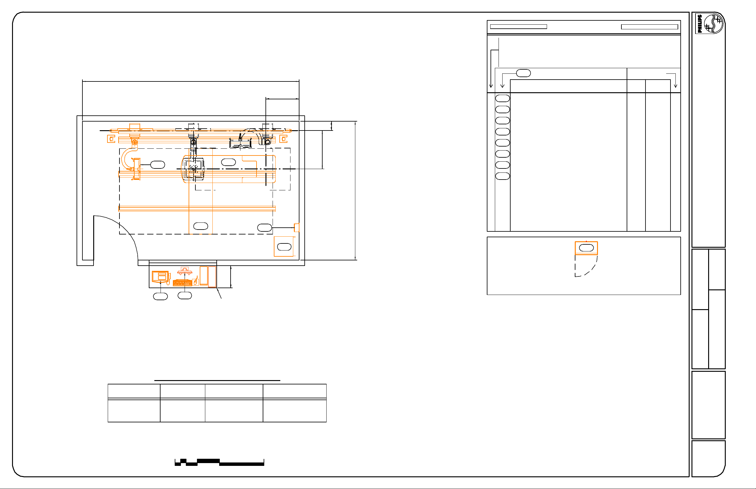
19'-6"
Table Floorplate Centerline
3'-0"
Equipment Legend
A
Furnished and installed by Philips
B
Furnished by customer/contractor and installed by customer/contractor
C
Installed by customer/contractor
Furnished by Philips and installed by contractor
D
E
Existing
F
Future
G
Option
Equipment Designation
Description
A
Detail Sheet
Weight
Heat Load
(btu/hr)(lbs)
1707462Optimus 80 Control Cabinet (40E Rack)ME
12.18.07
AD1
4' Wide Patient Entry
(Recommended)
DVM
PBC
DDW
MU
MS
2'-0"
Counter provided and
installed by customer
SCU
ME
10"
Floor Rail
Centerline
3'-5 1/2"
Table Longitudinal Centerline
12'-6"
A
A
A
A
A
A
A
MSC
Final location to be coordinated with the customer and architect of record.
AD1
1379Optimus Control PanelPBC
AD1
1297810CS 2 Tube Crane w/ Cable Carrier RailMU
AD1
060Manual Storage CabinetMSC
AD1
11914Segment Control UnitSCU
AD2
444753Digital Diagnost VM (Left)DVM
AD2
2083176Digital Diagnost WorkstationDDW
AD2
341472Single Sided Table TH-SMS
Not Site Specific
Digital Diagnost VM
- Standard Reference Drawing -
Date
Equipment Layout
Wall Stand Tube Position
Digital
Diagnost VM
Reported Existing Ceiling Height : None
Ceiling heights (from finished floor to bottom of Unistrut) other than
recommended may impact equipment functionality; consult with Philips.
0 8'1'
Minimum/Preferred
Ceiling Height
2'
4'
9' - 10 1/8" (3000mm)8' - 8 3/8" (2650mm)Upper Position
11' - 1 3/4" (3400mm)9' - 11 3/4" (3040mm)Lower Position
Maximum
Ceiling Height
Quote Number O.A. Number
Drawn By
N-SRD040005
Project Number
A1
Sheet 3 of 17
THE INFORMATION IN THIS PACKAGE IS PROVIDED AS A CUSTOMER CONVENIENCE, AND IS NOT TO BE CONSTRUED AS ARCHITECTURAL DRAWINGS OR CONSTRUCTION DOCUMENTS.
Philips assumes no liability nor offers any warranty for the fitness or adequacy of the premises or the utilities available at the premises in which the equipment is to be installed, used, or stored.
Page 4

Optional Wall Mounting Bracket
12.18.07
max.
107.47"
2730mm
25.59"
650mm
8.27"
210mm
min.
49.22"
1250mm
90°
90°
Option:
Tomo
Option:
Tomo
92.13"
9.57"
243mm
max.
2340mm
33.86"
min.
860mm
14.96"
380mm
92.76"
2356mm
34.41"
874mm
Option:
Tomo
57.87"
1470mm
9.49"
241mm
*
Option:
Tomo
25.59"
36.00"
914mm
9.49"
241mm
650mm
Option:
Rail for
Cable Carrier
4.49"
114mm
3.07"
78mm
6.00"
152mm
PBC
Weight
Heat Dissipation
15.75"
400mm
16.93"
430mm
Optimus Control Panel
9 lbs (4 kg)
137 Btu/hr (35 kcal/hr)
11.03"
13.19"
335mm
280mm
.79"
20mm
(07.0)
24.02"
610mm
30.00"
762mm
Max. weight of cabinet with manuals = 260 lbs. (118 kg)
MSC
Weight
Heat Dissipation
Manual Storage Cabinet
14.02"
356mm
60 lbs (27 kg)
0 Btu/hr ( 0 kcal/hr)
2.56"
65mm
(03.0)
Not Site Specific
Digital Diagnost VM
- Standard Reference Drawing -
8x45º
11.81"
300mm
Option:
Tomo
Supporting Arm UpSupporting Arm Down
* Column movement range = 1260mm (49.61");
standard range of 1470mm reduced by 210mm
(8.28") to allow optional cable carrier to be
mounted on transverse carriage.
* Optional cable carrier can be mounted on
longitudinal rail, causing 210mm (8.28") of
tube crane coverage loss (foot or head-end).
MU
Weight
Heat Dissipation
* Extension Rails are an additional 113lbs (51kg).
CS 2 Tube Crane
8x45º
Longitudinal
Rail
(368 kg)810 lbs
(326 kcal/hr)1297 Btu/hr
Transverse
Carriage
Option:
Cable Carrier
(07.1)
5.47"
139mm
8.94"
227mm
Cable
Openings
SCU
Weight
Heat Dissipation
21.06"
535mm
1.97"
50mm
42.50"
1080mm
±
Segment Control Unit
14 lbs (6 kg)
119 Btu/hr (30 kcal/hr)
(07.0)
2.76"
70mm
Clear Area
Around Cabinet
ME
Weight
Heat Dissipation
20.48"
520mm
21.66"
550mm
Optimus 50/65/80 Control Cabinet
2.76"
70mm
7.88"
200mm
76.98"
1955mm
462 lbs (210 kg)
1707 Btu/hr (430 kcal/hr)
Filler Panel
(07.0)
Date
Quote Number O.A. Number
Drawn By
N-SRD040005
Project Number
AD1
Sheet 4 of 17
THE INFORMATION IN THIS PACKAGE IS PROVIDED AS A CUSTOMER CONVENIENCE, AND IS NOT TO BE CONSTRUED AS ARCHITECTURAL DRAWINGS OR CONSTRUCTION DOCUMENTS.
Philips assumes no liability nor offers any warranty for the fitness or adequacy of the premises or the utilities available at the premises in which the equipment is to be installed, used, or stored.
Page 5
22.44"
177.17"
4500mm
143.70"
A
3650mm
B
max.
guide rail
570mm
Side
Side
30°
max
19.92"
506mm
8.07"
205mm
Top
20.32"
516mm
12.18.07
cable carrier
for CS 2/4
.63"
13.27"
337mm
min.
max.
9.06"
230mm
13.38"
340mm
13.78"
350mm
16mm
A
52.83"
1342mm
B
guide rail
74.80"
1900mm
User side left User side right (default)
22.64"
575mm
23.46"
596mm
6.89"
175mm
39.37"
1000mm
192.91"
4900mm
52.83"
1342mm
52.83"
1342mm
29.53"
750mm
74.80"
1900mm
41.54"
1055mm
cable carrier
for wall stand
min.
5.39"
137mm
27.56"
700mm
13.78"
350mm
59.06"
1500mm
13.78"
350mm
Required for insertion
of column
8.07"
205mm
Front
17.52"
445mm
CPU (Sun Ultra 25)
Weight: 60 lbs (27 kg)
Heat Dissipation: 1707 btu/hr (430 kCal/hr)
DDW
Weight
Heat Dissipation
center of gravity
table
13.80"
350mm
48.31"
1227mm
8.66"
220mm
center of gravity
table & patient
78.27"
1988mm
15.91"
404mm
Front
15.98"
406mm
19 " LCD Color Monitor
Weight: 16 lbs (8 kg)
Heat Dissipation: 171 btu/hr (43 kCal/hr)
Digital Diagnost Workstation
center of gravity
patient
2.13"
54mm
max.
min.
20.08"
510mm
35.83"
910mm
8.31"
211mm
Front
12.01"
305mm
UPS
Weight: 100 lbs (46 kg)
Heat Dissipation: 205 btu/hr (93 kCal/hr)
(07.0)
(81 kg)176 lbs
(566 kCal/hr)2083 Btu/hr
29.53"
750mm
35.83"
910mm
max.
20.08"
510mm
15.87"
403mm
min.
Not Site Specific
Digital Diagnost VM
- Standard Reference Drawing -
Date
97.64"
2480mm
93.70"
2380mm
7.22"
183mm
Guide rail to be supported using ceiling holders (A) OR wall holders (B)
DVM
Weight
Heat Dissipation
18.10"
460mm
41.54"
1055mm
Digital Diagnost VM
(342 kg)753 lbs
(112 kcal/hr)444 Btu/hr
(06.0)
wall clearance required for
installation and service of table base
7.87"
200mm
29.53"
750mm
7.87"
200mm
min.
cable
outlet
15.75"
400mm
35.43"
900mm
5.55"
141mm
floor plate
Weight
Heat Dissipation
wall clearance required for insertion of tabletop
118.11"
min.
3000mm
81.89"
2080mm
17.72"
450mm
66.14"
1680mm
102.36"
2600mm
MS
Single Sided Table TH-S
472 lbs (214 kg)
341 Btu/hr (86 kcal/hr)
49.21"
1250mm
wall clearance required for
installation and service of table base
(06.0
Quote Number O.A. Number
Drawn By
N-SRD040005
Project Number
AD2
Sheet 5 of 17
THE INFORMATION IN THIS PACKAGE IS PROVIDED AS A CUSTOMER CONVENIENCE, AND IS NOT TO BE CONSTRUED AS ARCHITECTURAL DRAWINGS OR CONSTRUCTION DOCUMENTS.
Philips assumes no liability nor offers any warranty for the fitness or adequacy of the premises or the utilities available at the premises in which the equipment is to be installed, used, or stored.
Page 6
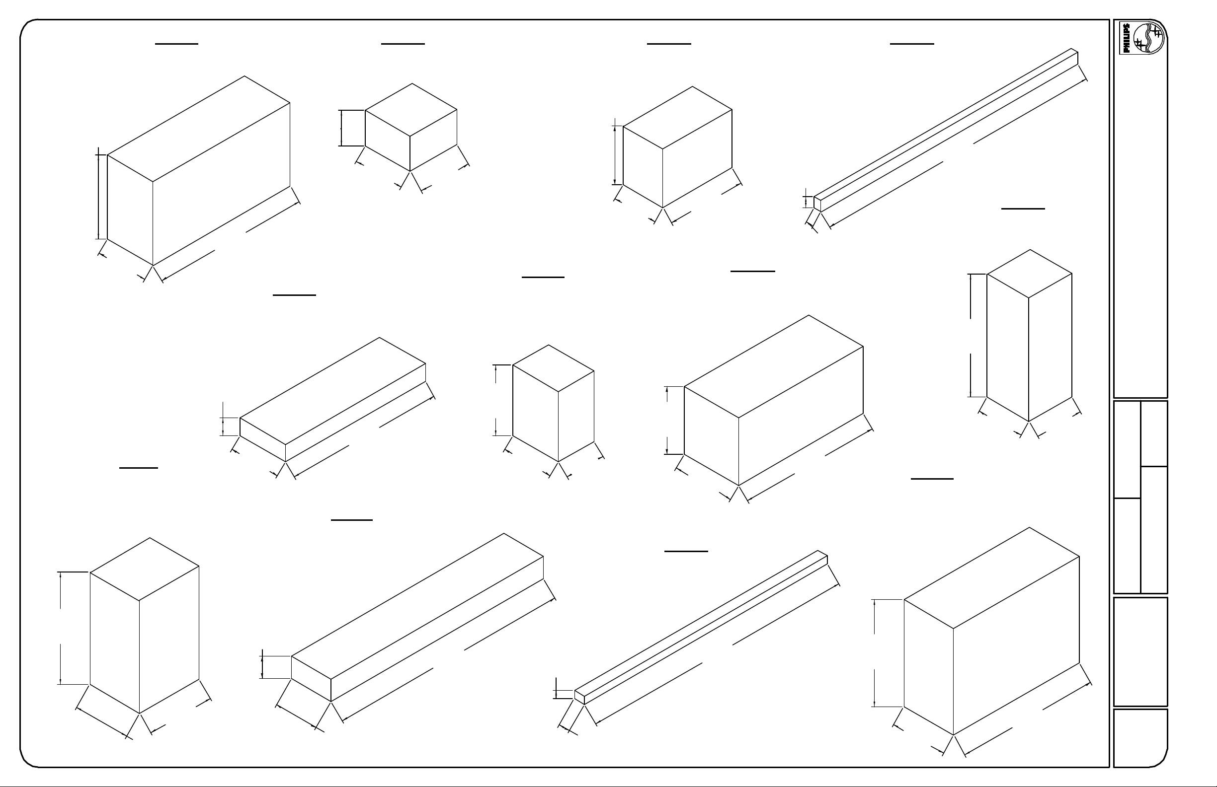
4'-8.30"
1430mm
2'-11.43"
900mm
Crate A
Moveable Column
Weight: 629 lbs.
8'-10.30"
2700mm
1'-11.62"
600mm
Crate E
Single Sided Table TH-S
Table Top
Weight: 270 lbs.
Crate B
Flat Detector
Weight: 99 lbs.
2'-10.65"
880mm
3'-.22"
920mm
Digital Bucky Unit with Swivelling Arm
Crate F
Single Sided Table TH-S
Table Base
Weight: 450 lbs.
Crate C
Weight: 281 lbs.
3'-3.37"
1000mm
2'-6.71"
780mm
7.87"
200mm
4'-5.54"
1360mm
5.12"
130mm
Crate G
Single Sided Trolley TF-M
Weight: 584 lbs.
Crate D
Floor Rail and Guide Rail
Weight: 135 lbs.
16'-6.82"
5050mm
Generator Cabinet
6'-10.68"
12.18.07
Crate H
Weight: 508 lbs.
Not Site Specific
Digital Diagnost VM
- Standard Reference Drawing -
2100mm
Crate I
CS4 Transverse Carriage
Weight: 562 lbs.
Tomography (option)
Additional Weight: 67 lbs.
6'-3.59"
1920mm
11.81"
300mm
2'-11.43"
900mm
9'-.27"
2750mm
Crate J
CS4 Longitudinal Carriage
Weight: 429 lbs.
1'-2.97"
380mm
13'-8.56"
4180mm
3'-11.24"
1200mm
2'-11.43"
900mm
5.50"
140mm
2'-3.56"
700mm
3'-9.28"
1150mm
3'-6.13"
1070mm
Crate K
CS Base Rails 4.3 m
Weight: 198 lbs.
15'-8.19"
4780mm
8'-.46"
2450mm
2'-8.28"
820mm
Crate L
CS2 Complete
Weight: 931 lbs.
Tomography (option)
Additional Weight: 67 lbs.
5'-11.65"
1820mm
2'-9.07"
840mm
Date
Quote Number O.A. Number
Drawn By
N-SRD040005
Project Number
3'-2.58"
980mm
3'-10.06"
1170mm
2'-6.72"
780mm
7.88"
200mm
3'-2.59"
980mm
8'-1.25"
2470mm
(06.0)
AD3
Sheet 6 of 17
THE INFORMATION IN THIS PACKAGE IS PROVIDED AS A CUSTOMER CONVENIENCE, AND IS NOT TO BE CONSTRUED AS ARCHITECTURAL DRAWINGS OR CONSTRUCTION DOCUMENTS.
Philips assumes no liability nor offers any warranty for the fitness or adequacy of the premises or the utilities available at the premises in which the equipment is to be installed, used, or stored.
Page 7

Equipment Support Information
1. General
The customer shall be solely responsible, at its expense, for preparation of the site, including
any required structural alterations. The site preparation shall be in accordance with this plan
and specifications, the architectural/construction drawings and in compliance with all safety and
building codes. The customer shall be solely responsible for obtaining all construction permits
from jurisdictional authority.
2. Equipment Anchorage
Philips provides, with this plan and specifications, information relative to equipment size,
weight, shape, anchoring hole locations and forces which may be exerted on anchoring
fasteners. The customer shall be solely responsible, through the engineer of record for the
building, to provide on the architectural/construction drawings, information regarding the
approved method of equipment anchoring to floors, wall and/or ceiling of the building. Any
anchorage test required by local authority shall be the customer's responsibility. Stud type
anchor bolts should not be specified as they hinder equipment removal for service. Consult
with Philips service prior to specifying anchor methods.
3. Floor Loading and Surface
Philips provides, with this plan and specifications, information relative to size, weight and shape
of floor mounted equipment. The customer shall be solely responsible, through the engineer of
record for the building, to provide on the architectural/construction drawings confirmation of the
structural adequacy of the floor upon which the equipment will be placed. Any load test
required by local authority, shall be the customer's responsibility.
The floor surface upon which Philips equipment is to be placed/anchored shall be flat and level
to within plus or minus 1/16 inch (2mm) over a length of 39" (1m).
4. Ceiling Support Apparatus
Philips provides, with this plan and specifications, information relative to size, weight and shape
of ceiling supported equipment. The customer shall be solely responsible, through the
engineer of record for the building, to provide on the architectural/construction drawings,
information regarding the approved method of structural support apparatus, fasteners and
anchorage to which Philips will attach equipment. Any anchorage and/or load test required by
local authority shall be the customer's responsibility.
12.18.07
Not Site Specific
Digital Diagnost VM
- Standard Reference Drawing -
Contractor to clearly mark Philips equipment longitudinal centerline on bottom of each structural
support.
The structural support apparatus surface to which Philips equipment is to be attached, shall
have horizontal equipment attachment surfaces parallel, square and level to within plus or
minus 1/16 inch (2mm).
Any drilling and/or tapping of holes required to attach Philips equipment to the structural
support apparatus shall be the responsibility of the customer.
Fasteners/anchors (i.e., bolts, spring nuts, lock and flat washers) and strip closures shall be
provided by the customer.
5. Lighting
Lighting fixtures shall be placed in such a position that they are not obscured by equipment or
its movement, nor shall they interfere with Philips ceiling rails and equipment movement or
otherwise adversely affect the equipment. Such lighting fixture locations shall be the sole
responsibility of the customer.
6. Ceiling Obstructions
There shall be no obstructions that project below the finished ceiling in the area covered by
ceiling suspended equipment travel.
7. Seismic Anchorage (For Seismic Zones Only)
All seismic anchorage hardware, including brackets, backing plates, bolts, etc., shall be
supplied and installed by the customer/contractor unless otherwise specified within the support
legend on this sheet. Installation of electronic cabinets to meet seismic anchorage
requirements must be accomplished using flush mounted expansion type anchor/bolt systems
to facilitate the removal of a cabinet for maintenance. Do not use threaded rod/adhesive
anchor systems. Consult with Philips regarding any anchor system issues.
8. Floor Obstructions/ Floor Coverings
There shall be no obstructions on the floor (sliding door tracks, etc.) in front of the Philips
technical cabinets. Floor must be clear to allow cabinets to be pulled away from the wall for
service.
Date
Quote Number O.A. Number
Drawn By
Contractor to verify with Philips the preferred floor covering installation method.
(05.0)
N-SRD040005
Project Number
SN
Sheet 7 of 17
THE INFORMATION IN THIS PACKAGE IS PROVIDED AS A CUSTOMER CONVENIENCE, AND IS NOT TO BE CONSTRUED AS ARCHITECTURAL DRAWINGS OR CONSTRUCTION DOCUMENTS.
Philips assumes no liability nor offers any warranty for the fitness or adequacy of the premises or the utilities available at the premises in which the equipment is to be installed, used, or stored.
Page 8

F2
F4
Table Floorplate Centerline
3'-0"
2'-2"
10"
3'-5 1/2"
Floor Rail
Centerline
Floor Support Legend
Furnished and installed by Philips
A
Furnished by customer/contractor and installed by customer/contractor
B
Installed by customer/contractor
C
Furnished by Philips and installed by contractor
D
Existing
E
Future
F
G
Item Number
Description
F1
D Single Sided Table TH-S Flush Mounted Floorplate SD2
F2
B Digital Diagnost VM Floor Rail Anchorage SD1
F3
Manual Storage Cabinet Anchorage SD2B
Floor must be level within this area - See note "3. Floor Loading and Surface" on
F4
sheet SN
F5
Segment Control Unit Anchorage (not shown) SD1B
Detail Sheet
SNB
12.18.07
Not Site Specific
Digital Diagnost VM
F1
F4
Table Longitudinal Centerline
CUSTOMER / CONTRACTOR SHALL RECOMMEND
AND / OR PROVIDE EQUIPMENT ANCHORING SYSTEMS
(I.E. "HILTI", "REDHEAD", ETC) BASED UPON SPECIFIED
"PULL" FORCES AND WALL / CEILING / FLOOR COMPOSITIONS.
F3
Final location to be coordinated with the customer and architect of record.
All dimensions must be off the final finished wall.
If a wall is furred out to hide electrical duct or boxes, the dimensions included in this plan
must come off the finished furred wall.
- Standard Reference Drawing -
Date
Quote Number O.A. Number
Drawn By
Floor Support Layout
Wall Stand Tube Position
Digital
Diagnost VM
Upper Position 8' - 8 3/8" (2650mm) 9' - 10 1/8" (3000mm)
Lower Position 9' - 11 3/4" (3040mm) 11' - 1 3/4" (3400mm)
Ceiling heights (from finished floor to bottom of Unistrut) other than
recommended may impact equipment functionality; consult with Philips.
0
Minimum/Preferred
Ceiling Height
4'2'1'
8'
Maximum
Ceiling Height
N-SRD040005
Project Number
S1
Sheet 8 of 17
THE INFORMATION IN THIS PACKAGE IS PROVIDED AS A CUSTOMER CONVENIENCE, AND IS NOT TO BE CONSTRUED AS ARCHITECTURAL DRAWINGS OR CONSTRUCTION DOCUMENTS.
Philips assumes no liability nor offers any warranty for the fitness or adequacy of the premises or the utilities available at the premises in which the equipment is to be installed, used, or stored.
Page 9

10'-0"
11 1/2"
4'-1/2"
2'-10 7/16"
C2
13'-3"
12'-5"
C3
C1
Table Floorplate Centerline
C1
C2
3'-0"
10"
Floor Rail
Centerline
3'-5 1/2"
Table Longitudinal Centerline
Ceiling Support Legend
Furnished and installed by Philips
A
Furnished by customer/contractor and installed by customer/contractor
B
Installed by customer/contractor
C
Furnished by Philips and installed by contractor
D
Existing
E
Future
F
G
Item Number
Description
C1
Philips Equipment Rails SD2A
C2
Unistrut (P1001 or equal) mounted flush with finished ceiling SD2B
C3
A
Philips Equipment Guide Rail SD1
CUSTOMER / CONTRACTOR SHALL RECOMMEND
AND / OR PROVIDE EQUIPMENT ANCHORING SYSTEMS
(I.E. "HILTI", "REDHEAD", ETC) BASED UPON SPECIFIED
"PULL" FORCES AND WALL / CEILING / FLOOR COMPOSITIONS.
12.18.07
Detail Sheet
/SD2
Not Site Specific
Digital Diagnost VM
- Standard Reference Drawing -
4'-1 3/4" 4'-1 3/4" 4'-1 3/4"
No obstructions below the
finished ceiling within this
area (i.e. sprinklers, lights,
etc.). See sheet SN for more
details.
Ceiling Support Layout
Tube PositionWall Stand
Minimum/Preferred
Ceiling Height
Maximum
Ceiling Height
All dimensions must be off the final finished wall.
If a wall is furred out to hide electrical duct or boxes, the dimensions included in this plan
must come off the finished furred wall.
Date
Quote Number O.A. Number
Drawn By
Digital
Diagnost VM
9' - 10 1/8" (3000mm)8' - 8 3/8" (2650mm)Upper Position
11' - 1 3/4" (3400mm)9' - 11 3/4" (3040mm)Lower Position
Ceiling heights (from finished floor to bottom of Unistrut) other than
recommended may impact equipment functionality; consult with Philips.
08'1' 2' 4'
N-SRD040005
Project Number
S2
Sheet 9 of 17
THE INFORMATION IN THIS PACKAGE IS PROVIDED AS A CUSTOMER CONVENIENCE, AND IS NOT TO BE CONSTRUED AS ARCHITECTURAL DRAWINGS OR CONSTRUCTION DOCUMENTS.
Philips assumes no liability nor offers any warranty for the fitness or adequacy of the premises or the utilities available at the premises in which the equipment is to be installed, used, or stored.
Page 10

177.17"
4500mm
Ceiling mounting device for the top guide rail
3.15"
80mm
3.15"
80mm
.39"
.79"
160mm
10mm
20mm
6.30"
.28"
7mm
cover
12.18.07
97.64"
2480mm
192.91"
4900mm
Ceiling Height
104.33" (2650mm) - 105.55" (2681mm)
105.51" (2680mm) - 113.94" (2894mm)
113.70" (2888mm) - 137.40" (3490mm)
guide rail
floor rail
Required Ceiling Holder
Short
Medium
Long
Part Number
4512 201 0218x
4512 201 0219x
4512 201 0220x
F5
Floor rail detail (side view)
3.54"
90mm
2.87"
73mm
A
cable outlet
.79"
.79"
20mm
** Not to scale
Weight of Segment Control box:
14 lbs. (10 kg.)
4.72"
120mm
20mm
1.97"
50mm
±
46.18"
1173mm
Recommended fixation:
4 mm x 8 mm dowel
4 mm x 6 mm screws, length >50 mm
Digital Diagnost VS Segment Control Unit
Wall Mounting Detail
The customer's architect/engineer of record shall specify
a wall backing plate sufficient for the bolt forces shown.
1.97"
50mm
±
59.57"
1513mm
Not Site Specific
Digital Diagnost VM
- Standard Reference Drawing -
(04.0)
Date
200mm
7.87"
500mm
19.69"
500mm
19.69"
500mm
19.69"
500mm
19.69"
Floor rail detail
4900mm
192.91"
500mm
19.69"
*Drawing not to scale
500mm
19.69"
500mm
19.69"
500mm
19.69"
500mm
19.69"
200mm
7.87"
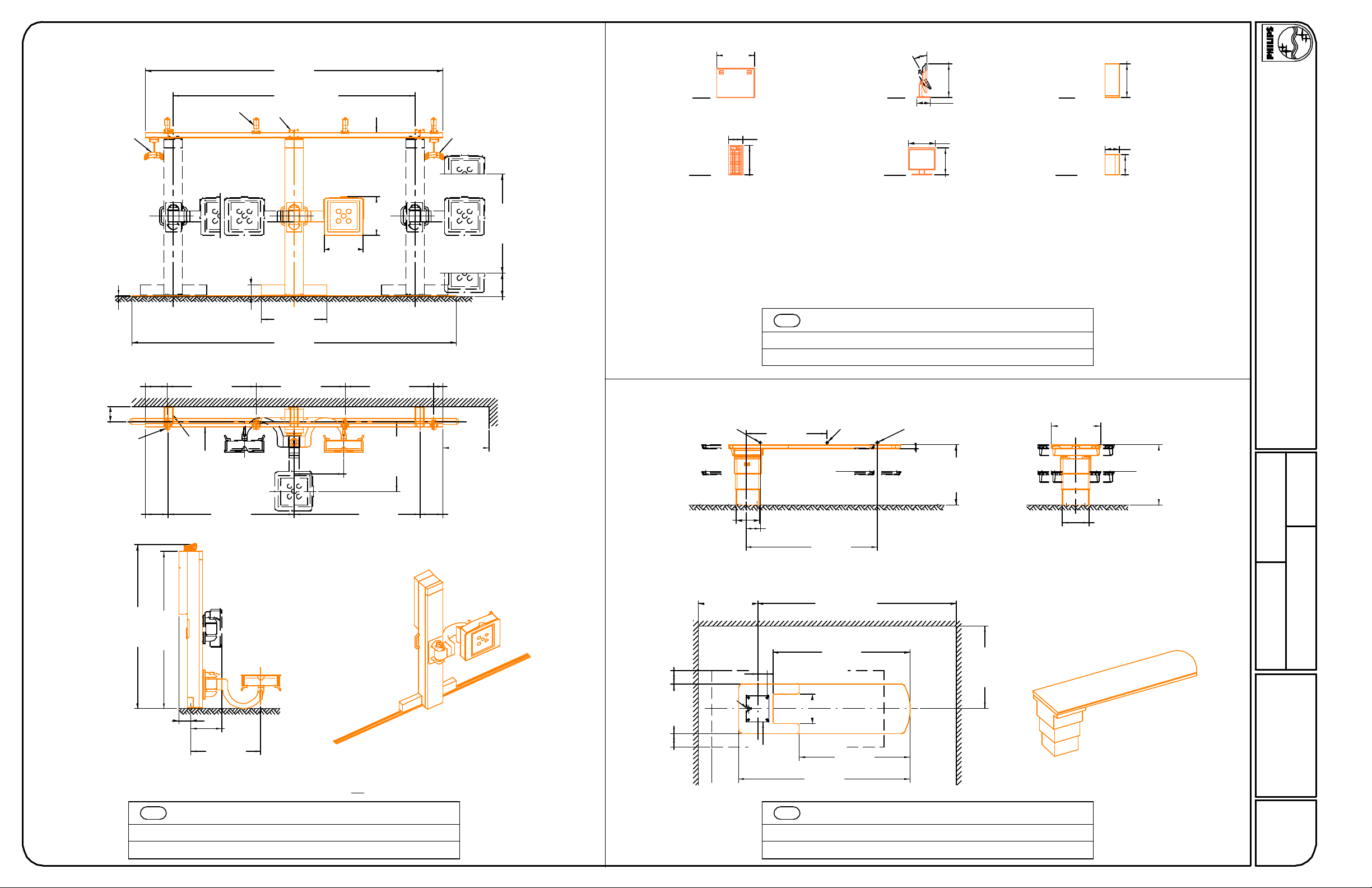
Detail - Digital Diagnost VM Floor Rail & Guide Rail Support (w/ ceiling holders)
Bolt Forces:
T max (Tension)(ceiling) = 870 lbs/bolt
V max (Shear)(ceiling) = 174 lbs/bolt
V max (Shear)(floor) = 180 lbs/bolt
F2
C3
(07.0)
0.63"
16mm
1.44"
36.5mm
min. 9.06"
A - Phillips screw 5 x 60 + 8 mm (or equivalent) dowels for concrete floors
230mm
CUSTOMER / CONTRACTOR SHALL RECOMMEND
AND / OR PROVIDE EQUIPMENT ANCHORING SYSTEMS
(I.E. "HILTI", "REDHEAD", ETC) BASED UPON SPECIFIED
"PULL" FORCES AND WALL / CEILING / FLOOR COMPOSITIONS.
Quote Number O.A. Number
Drawn By
N-SRD040005
Project Number
SD1
Sheet 10 of 17
THE INFORMATION IN THIS PACKAGE IS PROVIDED AS A CUSTOMER CONVENIENCE, AND IS NOT TO BE CONSTRUED AS ARCHITECTURAL DRAWINGS OR CONSTRUCTION DOCUMENTS.
Philips assumes no liability nor offers any warranty for the fitness or adequacy of the premises or the utilities available at the premises in which the equipment is to be installed, used, or stored.
Page 11

Self-locking
Bolt, M10x40
Clip Rail
Detail - Clip Rail Cross-section
Finished Ceiling
6.25"
159mm
5.93"
150.7mm
3.98"
101mm
2.85"
72.5mm
P1001 (or equal) Unistrut
Fixing Block
Fixing Block
Clip
Cover
3.94"
* Philips does not specify the overhead equipment support structure.
Unistrut (or equal) may or may not be used. If Unistrut are used, it is
up to Unistrut and the structural engineer for the project to
determine which of it's products are appropriate for each project.
P1001 Unistrut may not be appropriate given the equipment
weight on a specific project.
* Finished ceiling must NOT be lower than the bottom of
the Unistrut in order to prevent damage to the finished ceiling
during the installation of clip rails.
* Nothing shall be attached to the Unistrut with any fastener that
protrudes into the unistrut which would interfere with positioning of
the fixing block.
1.30"
1.26"
32mm
0.55"
14mm
100mm
Floor Plate
(side view)
Mount tablebase to floorplate: Mount floorplate to floor:
Bolt Forces:
T max (Tension) = 3377 lbs/bolt
V max (Shear) = 735 lbs/bolt
* NOTE: Floorplate must be mounted flush with the finished floor
F1
(07.0)
12.99"
330mm
15.59"
396mm
Floor Plate*
(top view)
33mm
Bolt Forces:
T max (Tension)(floor) = 2040 lbs/bolt
V max (Shear)(floor) = 506 lbs/bolt
Detail - Single Sided TH-S Table Base and Floor Plate
0.53"
14mm
11.02"
280mm
13.54"
344mm
Drawings Not to Scale
Base Transverse
Centerline
0.43"
11mm
7.87"
200mm
0.75"
19mm
Table cover
0.59"
15mm
15.87"
403mm
Table Base
(top view)
8.27"
210mm
cable
outlet
7.09"
180mm
750mm
1.97"
50mm
29.53"
Base Longitudinal
Centerline
floor plate
Table base
Table top
Table base
mounting holes
Floor plate
mounting holes
6.69"
170mm
13.80"
4.29"
109mm
1.38"
35mm
4.65"
351mm
118mm
102.36"
2600mm
12.18.07
Not Site Specific
Digital Diagnost VM
- Standard Reference Drawing -
1.25"
32mm
Tube Crane
Support Forces
CS2
CS4
C2C1 C3
5.88"
150mm
Detail - Fixing Block for Philips Ceiling Rails (Clip Rails)
(Tension) Tmax = 794 lbs/support
(Shear) Vmax = 134 lbs/support
(Tension) Tmax = 686 lbs/support
(Shear) Vmax = 160 lbs/support
(07.2)
(Tension) Tmax = 891 lbs/support
(Shear) Vmax = 149 lbs/support
(Tension) Tmax = 756 lbs/support
(Shear) Vmax = 175 lbs/support
0.63"
16mm
With Trauma AttachmentWith Tomo OptionWithout Tomo Option
(Tension) Tmax = 1106 lbs/support
(Shear) Vmax = 158 lbs/support
(Tension) Tmax = 887 lbs/support
(Shear) Vmax = 184 lbs/support
20.00"
508mm
Backing
Plates
Bolt Forces:
(Tension) Tmax = 107 lbs/bolt
(Shear) Vmax = 146 lbs/bolt
26.00"
660mm
Manual Storage Cabinet Mounting Detail
The customer's architect/engineer of record shall
specify a wall backing plate sufficient for the bolt
forces shown.
F3
(07.0)
Date
Quote Number O.A. Number
Drawn By
N-SRD040005
Project Number
SD2
Sheet 11 of 17
THE INFORMATION IN THIS PACKAGE IS PROVIDED AS A CUSTOMER CONVENIENCE, AND IS NOT TO BE CONSTRUED AS ARCHITECTURAL DRAWINGS OR CONSTRUCTION DOCUMENTS.
Philips assumes no liability nor offers any warranty for the fitness or adequacy of the premises or the utilities available at the premises in which the equipment is to be installed, used, or stored.
Page 12

General Electrical Information
1. General
The customer shall be solely responsible, at its expense, for preparation of the site, including any required electrical alterations. The site preparation
shall be in accordance with this plan and specifications, the architectural/construction drawings and in compliance with all safety and electrical codes, the
customer shall be solely responsible for obtaining all electrical permits from jurisdictional authority.
2. Materials and Labor
The customer shall be solely responsible, at its expense, to provide and install all electrical ducts, boxes, conduit, cables, wires, fittings, bushing, etc., as
separately specified herein.
3. Electrical Ducts and Boxes
Electrical ducts and boxes shall be accessible and have removable covers. Floor ducts and boxes shall have watertight covers. Ducts shall be divided
into as many as three separate channels by metal dividers, separately specified herein, to separate wiring and/or cables into groups as follows: Group a,
power wiring and/or cables. Group b: signal and/or data and protective ground wiring and/or cables. Group c: x-ray high voltage cables, the use of 90
deg. ells is not acceptable. On ceiling duct and wall duct use 45 deg. bends at all corners. All intersecting points in duct to have cross over tunnels
supplied and installed by contractor to maintain separation of cables.
4. Conduit
Conduit point - to - point runs shall be as direct as possible. Empty conduit runs used for cables may require pull boxes located along the run. Consult
with Philips. A pull wire or cord shall be installed in each conduit run. All conduits which enter duct prior to their termination point must maintain
separation from other cables via use of dividers, cross over tunnels, or flex conduit supplied and installed by contractor from entrance into duct to exit
from duct.
5. Conductors
All conductors, separately specified, shall be 75° c stranded copper, rung out and marked.
6. Disconnecting Means
A disconnecting means shall be provided as separately specified.
7. Warning Lights and Door Switches
"X-Ray On" warning lights and x-ray termination door switches should be provided at all entrances to x-ray rooms as required by code.
8. Dimmer Switches
X-ray room lights should be provided with dimmer switches.
(02.0)
Electrical Legend
Furnished and installed by Philips
A
Furnished by customer/contractor and installed by customer/contractor
B
Installed by customer/contractor
C
Furnished by Philips and installed by contractor
D
Existing
E
Future
F
G
Item Number
Description
CB
ST
ME
PBC
SCU
MS
DVM
480V, 3 phase 100 AMP circuit breaker with shunt trip and load side pressure lugs for #2 A.W.G. extra-flexible
cable (T+B type 31009 "locktight" or similar). Run power from breaker to wall box "ME" leaving an 8' tail. See
sheet "ED1" for power quantity requirements. Location per local code or owner requirements. Coordinate with
local Philips service.
Shunt trip (emergency off) - large mushroom-head button on remote control station with contacts to operate
feature of "CB." (if required by local code or owner, and mandatory for VA and D.O.D. installations). Its location
must be within easy reach but not subject to an accidental bump. Exact location to be determined by customer or
coordinated with local Philips Service. (Not shown on plan)
19 1/4"W x 67"H x 4"D flanged-edge terminal wall box with removable screw-type cover plate, surface mounted
75" A.F.F. to top of box. Conduits to terminate on top & sides of the box as required.
6"W x 6"L x 4"D pull box with removable screw-type cover plate, surface mounted 22" A.F.F. to bottom of box.
Location shown is recommended and may be changed - verify relocation with local Philips Service.
Grommetted opening on "WR1". Exact size to be determined in field. Modify cover of Segment Control Unit as
needed.
8"W x 8"L x 6"D floor box with removable gasketted screw-type cover plate. Top of box to be mounted 1.26"
below finished floor to accommodate flush mounted TH-S floor plate .
8"W x 8"L x 6"D ceiling box flush mounted with removable screw-type cover plate.
6"W x 6"L x 4"D pull box with removable screw-type cover plate, surface mounted 22" A.F.F. to bottom of box.
Location shown is recommended and may be changed - verify relocation with local Philips Service.
B
B
D
B
B
B
MU
B
B
DDW
Detail Sheet
ED1
ED1
Not Site Specific
- Standard Reference Drawing -
12.18.07
Digital Diagnost VM
Electrical Notes
1. The contractor will supply & install all breakers, shunt trip and incoming power to the breakers. The exact location of the breakers and shunt trips will
be determined by the architect or contractor.
2. The contractor shall supply & install all pull boxes, raceways, conduit runs, stainless steel covers, etc. Conduit/raceways must be free from burrs and
sharp edges over its entire length. A Greenlee pull string/measuring tape (part no. 435, or equivalent) shall be provided with conduit runs.
3. All pre - terminated, cut to length cables, will be supplied and installed by Philips Medical Systems. All cables to the breakers, will be supplied and
installed by the contractor, subject to local arrangements.
4. Provide and install 4 - 2" (50 mm) dia. Chase nipples between adjacent wall boxes where applicable.
5. Electrical raceway shall be installed with removable covers. The raceway should be accessible for the entire length. In case of non - accessible floors,
walls and ceilings, an adequate number of access hatches should be supplied to enable installation of cabling. Approved conduits may be substituted.
All raceways will be designed in a manner that will not allow cables to fall out of the raceway when the covers are removed. In most cases, this will
require above - ceiling raceway to be installed with the covers removable from the top. Raceway system as illustrated on this drawing are based upon
length of furnished cables. Any changes in routing of raceway system could exceed maximum allowable length of furnished cables. Conduit or raceway
above - ceiling must be kept as near to finished ceiling as possible.
6. Conduit sizes shall be verified by the architect, electrical engineer or contractor, in accordance with local or National Electrical Codes, whichever
govern.
7. Convenience outlets are not illustrated. Their number and location are to be specified by the customer/architect.
8. All sections of raceway and conduit shall be grounded with an independent #6 a.w.g.green wire that is to be attached using solderless lugs. All ceiling
mounted structural support members and ceiling plates shall also be grounded. All grounding connections, terminals, etc. Shall be installed in a manner
to provide accessibility for inspection, maintenance, repair, etc.
(99.0)
B
B
Warning light - provide an incandescent surface or flush mounted light fixture above door to indicate when X-Ray
WL
is on. Provide a 115V, 15A normally open relay in this fixture. (Not shown on plan)
Door switch - 120V, 5A switch limited to open when door is open. Mount in upper corner on strike side of main
DS
entry door(s) (Cooper no. 1665 or equivalent), if required by local code or physicist of record. (Not shown on plan)
ED1
ED1
Date
B
B
WR1
B
120 V / 20 A dedicated duplex outlet. Coordinate exact location with local Philips Service. (For Digital Diagnost
Workstation "DDW")
6"W x 3 1/2"D wall raceway with removable screw-type cover plate, surface mounted 63.5" A.F.F. to bottom of
raceway from side of "ME" to Segment Control Unit.
RJ45 type ethernet 10/100/1000 Mbit network connector. Access through customer's network to VPN device
N
capable of connecting to the Philips Remote Service Network (RSN) Datacenter is needed. Refer to page N1 for
RSN connectivity options. Locate within 10' of network card. Network Fiber optic and ethernet cabling,
connectors, wall boxes, patch panels, etc, are the responsibility of the purchaser. Philips assumes no
responsibility for procurement, installation, or maintenance of the components.
N1
E2
Quote Number O.A. Number
Drawn By
N-SRD040005
Project Number
EN
Sheet 12 of 17
THE INFORMATION IN THIS PACKAGE IS PROVIDED AS A CUSTOMER CONVENIENCE, AND IS NOT TO BE CONSTRUED AS ARCHITECTURAL DRAWINGS OR CONSTRUCTION DOCUMENTS.
Philips assumes no liability nor offers any warranty for the fitness or adequacy of the premises or the utilities available at the premises in which the equipment is to be installed, used, or stored.
Page 13

Refer to electrical legend - Sheet EN
9"
MU
Table Floorplate Centerline
13'-11" 1'-7"
9"
2 1/2"
3'-0"
DVM
10"
3'-5 1/2"
Floor Rail
Centerline
Conduit Required
General Notes
1. All conduit runs must take most direct route point to point.
2. All conduit runs must have a pull string.
Conduit supplied/installed by contractor - Philips cables installed by Philips
A
B
Conduit supplied/installed by contractor - Philips cables installed by contractor
Conduit and cables supplied and installed by contractor
C
Conduit existing - cables supplied and installed by Philips
D
Conduit existing - cables supplied by Philips, installed by contractor
E
Conduit existing - cables supplied and installed by contractor
F
Conduit
Run No. From
1
2
3
4
C
C 50'1/2"1 (P)WLME
Power
Panel
Conduit
Quantity
(* Cable
To
Type)
Minimum
Conduit
Size
per NEC per NEC1 (P)C CB
Default
Conduit
Length
50'2"1 (P)MECBB
50'3/4"1 (P)STCBC
*
Requirements
12.18.07
Power / Ground CablesP
Signal CablesS
Video CablesV
High Tension Power CablesH
Fiber OpticF
Special
2'-0"
PBC
2'-4"
N
DDW
MS
SCU
ME
1'-8"
1'-3"
WR1
Table Longitudinal Centerline
5
6
7
8
9
10
11
12
13
14
15
16
17
18
19
20
21
22
2"1 (S)DVMMEA 65'
2"1 (P)DVMMEA 65'
2"1 (P)DVMMEA 65'
2"1 (S)DVMMEA 65'
50'1/2"1 (P)DSMEC
65' 2"1 (P)PBCMEA
65' 2"1 (S)PBCMEA
52'1/2"1 (P)MSMEA
32'2 1/2"1 (S)MUMEA
32'2 1/2"1 (H)MUMEA
65'1 1/2"1 (S)DDWMEA
78'1 1/2"1 (S)DDWDVMA
78'1/2"1 (F)DDWDVMA
32'2"1 (S)MSMEA
32'2"1 (P)MSMEA
65'1 1/2"1 (S)DDWMEA
52'1 1/2"1 (S)MUMEA
52'1 1/2"1 (P)MUMEA
Grounding
Max. conduit length = 59' (each conduit) if
DVM2.
Grounding
Max. conduit length = 72' if DVM2.
Max. conduit length = 59' (each conduit) if
DVM2.
Runs #16 - #22 are for cables to/from SCU.
(Routed via ME and WR.)
Not Site Specific
Digital Diagnost VM
- Standard Reference Drawing -
Date
Quote Number O.A. Number
Drawn By
Electrical Layout
Tube PositionWall Stand
Digital
Diagnost VM
Ceiling heights (from finished floor to bottom of Unistrut) other than
recommended may impact equipment functionality; consult with Philips.
1' 2'
0 8'
Minimum/Preferred
Ceiling Height
9' - 10 1/8" (3000mm)8' - 8 3/8" (2650mm)Upper Position
11' - 1 3/4" (3400mm)9' - 11 3/4" (3040mm)Lower Position
4'
Maximum
Ceiling Height
All dimensions must be off the final finished wall.
If a wall is furred out to hide electrical duct or boxes, the dimensions
included in this plan must come off the finished furred wall.
N-SRD040005
Project Number
E1
Sheet 13 of 17
THE INFORMATION IN THIS PACKAGE IS PROVIDED AS A CUSTOMER CONVENIENCE, AND IS NOT TO BE CONSTRUED AS ARCHITECTURAL DRAWINGS OR CONSTRUCTION DOCUMENTS.
Philips assumes no liability nor offers any warranty for the fitness or adequacy of the premises or the utilities available at the premises in which the equipment is to be installed, used, or stored.
Page 14

Cable Trough Divisions
Troughs or ducts must be separated by metal barriers into three sections:
1. High voltage (H.T.) cables to be run separately from all other cables.
2. Power cables and ground cables can be run together.
3. Signal cables and data cables can be run together but must be separated
from power cables.
4. Video cables to be run separately from all other cables.
12.18.07
Power &
Grounds
5. It is important that all cables are placed in the appropriate trough and
at no given point do any cables from one division cross with cables
from another. Trough separation must be continuous from the beginning
to the end of the run. Utilize crossover tunnels as appropriate please see example below
6. Trough or ducts: steel with steel dividers grounded to building ground.
7. Contractor to provide cable restraints in all troughs.
8. No cables, except cables to & from the generator rack (ME) and transfomer,
must pass through the 20" (500mm) exclusion zone around the generator rack.
(For interventional procedures only)
Signal &
Data
Video
(if not in conduit)
High Tension
(if separate conduit
not used)
Crossover Example
Not Site Specific
Digital Diagnost VM
- Standard Reference Drawing -
Date
WR1
(03.2)
Quote Number O.A. Number
Drawn By
N-SRD040005
Project Number
E2
Sheet 14 of 17
THE INFORMATION IN THIS PACKAGE IS PROVIDED AS A CUSTOMER CONVENIENCE, AND IS NOT TO BE CONSTRUED AS ARCHITECTURAL DRAWINGS OR CONSTRUCTION DOCUMENTS.
Philips assumes no liability nor offers any warranty for the fitness or adequacy of the premises or the utilities available at the premises in which the equipment is to be installed, used, or stored.
Page 15

CB
Line Voltage Variation:
Frequency Variation:
Voltage Surges:
Voltage Sags:
Line Impulses:
Neutral-ground Impulses:
High Frequency noise:
Ground and Neutral
Conductor Impedance:
Power Quality Requirements
Optimus 80 / Optimus C
80 KWPower Output:
3 phase, 3 wire power and ground, Delta or wyeSupply Configuration:
400, 440, 460, or 480 VAC, 60 HzNominal Line Voltage:
± 8% steady-state
2% maximum of nominal voltage between phasesLine Voltage Balance:
± 1% (± 0.6 Hz)
To 110% of steady-state voltage 100 msecs.
Maximum duration, 6 per hour maximum
To 90% of steady-state voltage 100 msecs.
Maximum duration, 6 per hour maximum
1000 VPK above phase-neutral RMS absolute
maximum. No more than 1 impulse per hour to exceed
500 VPK.
2.0 volts maximum RMS valueNeutral-ground Voltage:
No more than 1 per hour that exceeds 25 volts and 1
Mjoule
3.0 volts steady-state maximum. Over 3.0 volts
permitted for 100 msec. maximum, 1 per hour
maximum.
0.1 Ohms @ 60 Hz maximum
Branch Circuit and Wire Gauge Requirements
Optimus 80 / Optimus C
150 KVABranch Power:
3 pole, 100 amperes (@ 480V)Circuit Breaker:
158 KVA (800 MA @ 100 KV) (Short-term)Maximum Instantaneous Power:
<8 Amps (Stand-by/Long-term)
Recommended conductor sizes for 1% impedance of branch conductors.
Based on 20°C copper conductors:
66.9 ft.#1 AWG
84.3 ft.1/0 AWG
106 ft.2/0 AWG
133 ft.3/0 AWG
169 ft.4/0 AWG
199 ft.250 MCM
239 ft.300 MCM
399 ft.400 MCM
359 ft.500 MCM
79 ft.
100 ft.
126 ft.
159 ft.
201 ft.
230 ft.
285 ft.
380 ft.
476 ft.
87 ft.
110 ft.
139 ft.
175 ft.
221 ft.
261 ft.
313 ft.
418 ft.
522 ft.
480 VAC460 VAC440 VAC400 VAC
96 ft.
121 ft.
152 ft.
192 ft.
242 ft.
287 ft.
344 ft.
459 ft.
574 ft.
CB
Electrical power distribution at the facility shall comply with:
Utilization voltages per ANSI C84.1 - 1982 range A.
Voltage to be supplied is 3 phase, 3 wire power and ground (delta or wye) unless otherwise noted
in equipment specifications.
Phase conductors to be sized for instantaneous voltage drop per NEC 517 - 73 and Philips
recommendations.
Neutral and ground conductors to be sized equivalently to phase conductors, unless
otherwise noted.
Metal conduit shall not be used as the equipment ground conductor.
Clamping type surge suppressors are highly recommended in addition to standing facility lighting
arrestors. Equipment to be protected from ANSI/IEEE C62.41-1980 location category B impulses.
ANSI / NFPA 70 - National Electrical Code
Article 250 - grounding
Article 517 - health care facilities
ANSI / NFPA 99 - health care facilities
NEMA standard XR0 - power supply guideline for x-ray machines
Eletrical Requirement Notes
Power Quality Guidelines
1. Power supplied to medical imaging equipment must be separate from power feeds to air
conditioning, elevators, outdoor lighting, and other frequently switched or motorized loads.
Such loads can cause waveform distortion and voltage fluctuations that can hinder high quality
imaging.
2. Equipment that utilizes the facility power system to transmit control signals (especially clock
systems) may interfere with medical imaging equipment, thus requiring special filtering.
3. The following devices provide a high impedance, nonlinear voltage source, which may affect
image quality:
Static UPS systems, Series filters, Power conditioners, and Voltage regulators.
Do not install such devices at the mains supply to medical imaging equipment without
consulting Philips installation or service personnel.
4. Line impedance is the combined resistance and inductance of the electrical system and
includes the impedence of the power source, the facility distribution system, and all phase
conductors between the source and the imaging equipment. Philips publishes recommended
conductor sizes based on equipment power requirements, acceptable voltage drops, and
assumptions about the facility source impedance. The minimum conductor size is based on
the total line impedance and NEC requirements. Unless impedance calculations are performed
by an electrical engineer, the recommended values must be used.
WL DS
ME
EZX1
Wall Box
"ME"
SW UN EX 4
PO26V
CMSW
RM DR CT
RM DR 0V
5
6
8
9
10
Relay Supplied by Philips
Detail for Connection of
X-Ray On Light and Door Switch
(Optimus Rad/RF Generator Only)
19.25"
489mm
Terminal Box
Finished Floor
Wall Box Mounting Detail
1/2" Conduit
Hospital
Supplied
110 VAC
Door Switch
67.00"
Radiation
Indication
1702mm
75.00"
1905mm
(01.0)
(99.1)
12.18.07
Not Site Specific
Digital Diagnost VM
- Standard Reference Drawing -
Date
Impedance
Drop
Maximum Load
Minimum copper wire size, circuit breaker to equipment: #2
190 A200 A210 A228 AInst. Current
0.2 Ω0.2 Ω0.2 Ω0.2 ΩMax. Phase-phase
38.0 V40.0 V42.0 V45.6 VMax. Load Voltage
7.9 %8.7 %9.5 %11.4 %Percent Regulation at
(06.0)
Quote Number O.A. Number
Drawn By
N-SRD040005
Project Number
ED1
Sheet 15 of 17
THE INFORMATION IN THIS PACKAGE IS PROVIDED AS A CUSTOMER CONVENIENCE, AND IS NOT TO BE CONSTRUED AS ARCHITECTURAL DRAWINGS OR CONSTRUCTION DOCUMENTS.
Philips assumes no liability nor offers any warranty for the fitness or adequacy of the premises or the utilities available at the premises in which the equipment is to be installed, used, or stored.
Page 16

Philips Medical Systems Remote Services Network (RSN)
Secure broadband connection required for Philips remote technical support, diagnostics, and applications assistance
12.18.07
Broadband Site-to-Site Connectivity (Preferred)
This connectivity method is designed for customers who prefer a
connection from the RSN Data Center to the Health Care Facility (HCF)
utilizing their existing VPN equipment.
Connectivity Details:
- A Site-to-Site connection from the RSN data center's Cisco router will be established to the
HCF's VPN concentrator
- The VPN Tunnel will be an IPSEC, 3DES encrypted Tunnel using IKE as standard, but
alternative standards are also available, such as AES, MD5, SHA, Security Association
lifetime and Encryption Mode
- Every system that we will be servicing remotely will have a static NAT IP that we configure
on the RSN Data center side.
HCF VPN
Concentrator
General Network
Router
Overview
(not site specific)
c
Internet
Shared VPN
Action Required by Hospital:
- Review and approve connection details
- Complete appropriate Site Checklist
- Configure and allow Site-to-Site access prior to setting up connectivity depending on the
access criteria that the HCF decides to implement (ex: Source IP filtering, destination IP
filtering, NAT assignment, etc.)
- Route traffic from within the hospital network with destination addresses 192.68.48.0/22 to
the designed IP provided by Philips
Health Care Facility
Philips
PACS
Ultrasound
Philips
Nuc Med
Hospital
Network
Patient
Monitoring
Philips
MR
Philips
X-Ray
Philips
CT
Broadband Router Installed at Health Care Facility
This connectivity method is designed for customers who have a dedicated high speed
connection for Philips equipment.
Connectivity Details:
- An RSN Cisco 1711 or 1712 router will be preconfigured and installed at the HCF by Philips
in conjunction with the HCF IT representative.
- The VPN Tunnel will be an IPSEC, 3DES encrypted Tunnel using IKE and will be
established from the RSN-DC and terminated at the RSN Router on-site
- One to One NAT is used to limit access to Philips eqiupment only
- Router Config and IP auditing is enabled for Customer IT to view via website 24/7
- Dedicated DSL connections are also supported
Option 1: Parallel to HCF Firewall Connectivity Method
This connectivity method is designed for customers who prefer a Philips RSN Router installed
on site utilizing all the security features provided and managed by Philips.
Philips
General Network
Router
Overview
(not site specific)
Firewalls
Internet
Philips VPN or
Site-to-Site VPN
Action Required by Hospital:
- Assign a fixed public IP Address from the ISP to be configured on the Philips router. This is
the DOTTED link on the picture connected to the firewall.
- Assign a Back end IP for the Philips router on the Hospital Network
- Complete appropriate Site Checklist
- Route traffic from within the hospital network with destination addresses 192.68.48.0/22 to
internal Philips router Ethernet interface. This is the DASHED line connected to the firewall.
Health Care Facility
Philips
PACS
Ultrasound
Philips
Nuc Med
Hospital
Network
Patient
Monitoring
Philips
MR
Philips
X-Ray
Philips
CT
Option 3: Router Installed Inside the HCF's DZM
This connectivity method is designed for customers who prefer the RSN Router installed inside
and existing, or new DMZ, allowing access to Philips equipment.
General Network
Overview
(not site specific)
Internet
Philips VPN or
Site-to-Site VPN
Philips
Router
Health Care Facility
Philips
Philips
PACS
Ultrasound
Nuc Med
Hospital
Network
Patient
Monitoring
Philips
MR
Philips
X-Ray
Philips
CT
Action Required by Hospital:
- Assign a fixed public IP Address from the ISP to be configured on the Philips router. This is
the DOTTED link on the picture connected to the firewall.
- Assign a Back end IP for the Philips router on the Hospital Network
- Complete appropriate Site Checklist
- Route traffic from within the hospital network with destination addresses 192.68.48.0/22 to
internal Philips router Ethernet interface. This is the DASHED line connected to the firewall.
- Configure and allow on the firewall on the DASHED line interface IPSec protocol
communication by opening protocol 500, 50, 51, 47 and port 23 + TACACS. Traffic should
be between external IP Address located on the Philips router and the RSN Data center IP
address 192.68.48/24 and IP address AOSN TACAS
- Configure and allow on the firewall on the DASHED line interface access between the IP
address allocated by the hospital to the Philips internal Ethernet router interface and the
target modality IP address
Not Site Specific
Digital Diagnost VM
- Standard Reference Drawing -
Date
Option 2: Back End Connected to the HCF Firewall Connectivity Method
This connectivity method is designed for customers who prefer a Philips RSN Router installed
on site by setting up an IP-Based policy allowing access thru existing HCF Firewall to Philips
equipment.
Health Care Facility
Philips
General Network
Overview
(not site specific)
Router
Philips
PACS
Internet
Philips VPN or
Site-to-Site VPN
Ultrasound
Action Required by Hospital:
- Assign a fixed public IP Address from the ISP to be configured on the Philips router. This is
the DOTTED link on the picture connected to the firewall.
- Assign a Back end IP for the Philips router on the Hospital Network
- Complete appropriate Site Checklist
- Route traffic from within the hospital network with destination addresses 192.68.48.0/22 to
internal Philips router Ethernet interface. This is the DASHED line connected to the firewall.
- Configure and allow on the firewall on the DASHED line interface access between the IP
address allocated by the hospital to the Philips internal Ethernet router interface and the target
modality IP address.
Philips
Nuc Med
Hospital
Network
Patient
Monitoring
Philips
MR
Philips
X-Ray
Philips
CT
Quote Number O.A. Number
Drawn By
N-SRD040005
Project Number
N1
Sheet 16 of 17
THE INFORMATION IN THIS PACKAGE IS PROVIDED AS A CUSTOMER CONVENIENCE, AND IS NOT TO BE CONSTRUED AS ARCHITECTURAL DRAWINGS OR CONSTRUCTION DOCUMENTS.
Philips assumes no liability nor offers any warranty for the fitness or adequacy of the premises or the utilities available at the premises in which the equipment is to be installed, used, or stored.
Page 17

Instructions
Questionnaire for DigitalDiagnost VM
Order No. :
Customer :
Project leader :
Phone No. :
mail :
Signature :
This form is to be used by Project Manager, Contractor and Service Engineer.
Information is used to develop and determine site ready date.
Items listed are go/no go items for delivery unless noted as delay only items.
Items identified with *** as delayed items must be completed after hours or on weekend. These itmes cannot be accomplished while installation is
in progress. Also, these items must be completed within two days of installation start or they may stop installation.
Site Readiness Checklist
Customer site preparation verified in general against the Philips final planning drawings.
Walls finished including painting.
Doors installed.
Floor leveled according to Philips drawings and specifications.
Floors are tiled/covered finished. Flooring is covered with protective covering (scratch protection).
Ceiling lights installed.
Cable conduit and ductwork installed and clean. Position checked. Duct covers in place but not finally closed. Cable opening are clear,
without sharp edges. Pull strings in conduit. Installation per Philips specifications.
HVAC environmental equipment installed and working according to Philips specifications.
Ceiling installation completed.
Electrical preparation according to Philips specifications.
All network cabling, drops installed according to Philips specifications (including hardcopy cameras).
All pre-cabling identified on Philips drawings has been installed.
Pre-move survey completed - Delivery route identified.
Lead glass installed ***.
X-ray warning lights installed ***.
Dedicated phone line for modem use***.
Room has been cleaned ***.
Cabinets and casework installed***.
Modality Checklist
Unistrut installed and level according to Philips specifications
Blocking support for wall stand
Conduit lenghts measured according to Philips specifications. NOTE: Specifications are from source box to destination box (not just conduit
run length)
Wall support for wall stand
Cataloque section 712-55 Direct Radiography)
This questionnaire must be used with your order.
Mark all items with a cross.
Fill in your special requests with help of the drawing Z-5.1 and forward it to your SSD order desk.
Bold * marked items = default.
Country :
e-
Siebel
catalogue
FRQ 3101 704-Q01
FRQ 3123 704-Q23 Generator → Workstation 20*
FDQ 5505 712-Q05 SCU2 → Workstation
FRQ 3121 704-Q21
Single Sided Table TH-S CAN → SCU2/Generator (PE)
General
FMS 0001 704-Q99 Country of delivery USA*
FMS 0002 712_Q98 Operator Manual Language ENG*
Generator
FMS 0003 Mains voltage (50/60Hz) 415-480V NMSA 604 / MRD 5781
Control desk version Desk version*
BuckyDiagnost CS
FRQ 3110 704-Q10 Ceiling height
NRDN 223 MRD 1821
NRDN 223 MRD 1821
NRDN 223 MRD 1821
NRDN 223 MRD 1821
NRDN 229 MDD 1521
NRDN 222 MRD 5581
NRDN 223 MRD 1821 E → Rail length (total) 4300 mm mm
Date :
PMS
catalogue
Cable lengths (m) from outlet to outlet
Generator → Generator control desk
Generator
Generator control desk → SCU2
Workstation
Generator → Segment control unit 2 (SCU2 )
Generator → BuckyDiagnost CS
SCU2 → BuckyDiagnost CS
Additional remarks:
< 3.0 m*
Tube support upper pos.
Length of ceiling rails
A → For longitudinal carriage rear side CS2 mm max. 100 mm
B → For longitudinal carriage front side CS2
A → For longitudinal carriage rear side CS4
B → For longitudinal carriage front side CS4
C → Option: Rail extension (CS2/4 + VM)
D → Rail separation (rail connection parts incl.)
Standard Reduction
2356 mm
4076 mm
2700 mm mm
0 mm mm
20*
20
20
24
6
20*
10*
16
10/16
>3.0 m
Tube support lower pos.
mm max. 500 mm
mm max. 500 mm
mm max. 900 mm
12.18.07
Not Site Specific
Digital Diagnost VM
- Standard Reference Drawing -
Date
Quote Number O.A. Number
Drawn By
Approved for Delivery
Project Manager Date
Service Engineer Date
DigitalDiagnost VM
FDQ 5523 712-Q23 Operation side DigitalDiagnost VM userside right*
FDQ 5038 704-Q38
Wall holder for min. room height 2650mm no
Ceiling holder for guide rail room height 2680-2894 (middle version)*
N-SRD040005
Project Number
CHK
Sheet 17 of 17
THE INFORMATION IN THIS PACKAGE IS PROVIDED AS A CUSTOMER CONVENIENCE, AND IS NOT TO BE CONSTRUED AS ARCHITECTURAL DRAWINGS OR CONSTRUCTION DOCUMENTS.
Philips assumes no liability nor offers any warranty for the fitness or adequacy of the premises or the utilities available at the premises in which the equipment is to be installed, used, or stored.
 Loading...