

Page 1
Philips Medical Systems
INTRODUCTION AND
TECHNICAL DATA
INSTALLATION
1
2
BuckyDiagnost TH2 / TF
(MSB)
9890 010 06503
LEVEL 1
DOCUMENTATION
FAULT FINDING
REPLACEMENTS
PROGRAMMINGS
ADJUSTMENTS
ACCEPTANCE
3
4
5
6
7
This document and the information contained in it is strictly reserved for
current Philips Medical Systems (”Philips”) personnel, Philips licensed
representatives and Philips customers who have purchased a valid
service agreement for use by the customer’s designated in-house
service employee on equipment located at the customer’s designated
site. Use of this document by unauthorized persons is strictly prohibited.
This document must be returned to Philips when the user is no longer
licensed and in any event upon Philips’ first written request.
Printed in Hamburg, Germany
© 2005 Koni nklijke Philips Electronics N.V.
ALL RIGHTS RESERVED
4512 984 29612 Vers. 00 1
regist er12_L1
SERVICE INFORMATION
DRAWINGS
SCHEMATIC DIAGRAMS
WIRING DIAGRAMS
8
Z1
Z2
Z3
Page 2

Proprietary Notice:
This document and the information contained in it is proprietary and
confidential information of Philips Medical Systems (”Philips”) and
may not be reproduced, copied in whole or in part, adapted, modified, disclosed to others, or disseminated without the prior written
permission of the Philips Legal Department. Use of this document
and the information contained in it is strictly reserved for current
Philips personnel and Philips customers who have a current and
valid license from Philips for use by the customer’s designated in-house service employee on equipment located at the customer’s
designated site. Use of this document by unauthorized persons is
strictly prohibited. Report violation of these requirements to the Philips Legal Department. This document must be returned to Philips
when the user is no longer licensed and in any event upon Philips’
first written request.
Warranty Disclaimer Language:
Philips provides this DOCUMENT without warranty of any kind, implied or expressed, including, but not limited to, the implied warranties of merchantability and fitness for a particular purpose.
Limitations of Liability Language:
Philips has taken care to ensure the accuracy of this document.
However, Philips assumes no liability for errors or omissions and reserves the right to make changes without further notice to any products herein to improve reliability, function, or design. Philips may
make improvements or changes in the product(s) or program(s) described in this document at any time.
CSIP Level 1
© 2005 Koninklijke Philips Electronics N.V.
ALL RIGHTS RESERVED
4512 984 29612 Vers. 002
regist er12_L1
Page 3

BuckyDiagnost TH2 / TF (MSB)
SERVICE MANUAL -- SUBSYSTEM
BuckyDiagnost TH2 / TF (MSB) Author: M. Bierstedt
Type No : 9890 010 06503
In case there are any questions concerning this manual,
please send this LOPAD via fax to 49/(0)40/5078 2481
File: BD_TH2_TF_MSB 29612Vers00
List of pages and drawings (LOPAD) Manual Order No: 4512 984 29612
released: 06/2005
1 ... 4
_________________________________
1--0.1 (05.0)
1--1...5 (05.0)
_________________________________
2--0.1 (05.0)
2--1...9 (05.0)
_________________________________
3--0.1 (05.0)
3--1...8 (05.0)
_________________________________
4--0.1 (05.0)
4--1...2 (05.0)
_________________________________
6--0.1 (05.0)
6--1...2 (05.0)
_________________________________
Z--0.1 (05.0)
Z--1.1 (04.0) A3 4512 982 0096.
Z--1.2 (04.0) A3 4512 982 0096.
2Z--10 (e/04.0) A3 4512 983 05451
________________________________
Z--0.2 (05.0)
Z1--1 (a/05.0) A3 DigiDiagn. TH
Z1--1.2 (05.0) A3
Z1--1.3 (05.0) A3
Z1--1.4 (05.0) A3
Z1--2 (05.0) A3
Z1--3 (d/05.0) A3 DigiDiagn. TH
Z1--5 (05.0) A3 DigiDiagn. TH
________________________________
Z2--1 (05.0) A3
Z2--3 (05.0) A3
Z2--4 (a/05.0) A3 DigiDiagn. TH
________________________________
Z3--1.1 (04.1) A4 DigiDiagn. TH
Z3--1.2 (05.0) A3 DigiDiagn. TH
Z3--2.1 (04.1) A4 DigiDiagn. TH
Z3--2.2 (04.1) A4 DigiDiagn. TH
Z3--3.1 (05.2) A3 DigiDiagn. VM
Z3--3.2 (05.0) A3 DigiDiagn. VM
Z3--4.1 (05.0) A3 BuckyDiag TH2
4512 984 29612 Vers. 00 3
BD_th2_TF_MSB_lopad
E 2005 Koninklijke Philips Electronics N.V.
ALL RIGHTS RESERVED
Page 4

Blank page
BuckyDiagnost TH2 / TF (MSB)
E 2005 Koninklijke Philips Electronics N.V.
ALL RIGHTS RESERVED
4512 984 29612 Vers. 00CSIP Level 1 (05.0)4
BD_th2_TF_MSB_lopad
Page 5

BuckyDiagnost TH2 / TF (MSB)
INTRODUCTION AND TECHNICAL DATA
Contents 1--0.1.......................................................
1. Purpose of the manual 1--1.............................................
2. Items supplied 1--1....................................................
3. Compatibility 1--2.....................................................
4. Technical data 1--3....................................................
4.1. Mechanical data 1--3....................................................
4.2. Environmental data 1--3.................................................
4.3. Electrical data 1--3......................................................
4.4. Tools / Material required 1--4.............................................
4.5. Network data 1--4......................................................
4.6. Remote service data 1--4................................................
4.7. Transport data 1--4.....................................................
4.8. Pre--installation requirements 1--4........................................
4.9. Movements 1--4........................................................
4.10. Pre--installation data 1--4................................................
INTRODUCTION AND TECHNICAL DATA
5. Saftey information 1--4.................................................
6. Compliance information 1--5...........................................
7. Equipment identification and labelling 1--5..............................
8. Abbreviations and definitions 1--5......................................
9. Manual history 1--5....................................................
BuckyDiagnost TH2 / TF (MSB) CSIP Level 1 (05.0) 1--0.1
BD_th2_TF_MSB_1_inh
E 2005 Koninklijke Philips Electronics N.V.
ALL RIGHTS RESERVED
Page 6

BuckyDiagnost TH2 / TF (MSB)
INTRODUCTION AND TECHNICAL DATA
1. Purpose of the manual
This documentation is valid for BuckyDiagnost TH2 / TF.
The table BuckyDiagnost TH2 / TF is part of the BuckyDiagnost family and can be installed together with the ceiling
suspension BuckyDiagnost CS, respectively the floor stand BuckyDiagnost FS and the X-ray generator OPTIMUS
RAD / OPTIMUS 30 single phase.
The table BuckyDiagnost TH2 is characterized by:
-- height-adjustable tablebase
-- floating tabletop
The table BuckyDiagnost TF characterized by:
-- fixed height tablebase
-- floating tabletop
2. Items supplied
BuckyDiagnost TH2
-- Table with floating tabletop, 750 mm x 2400 mm, Kevlar
-- Height sensor
-- Manual bucky unit, non-sensing
-- Grid for bucky unit
-- AMPLIMAT chamber
Options:
-- Manual bucky unit with format sensing
-- Automatic cassette loader (ACL4)
-- Tomo 2 device
-- Footswitch locking device
-- Second table control
-- Wider table top 850 mm x 2400 mm
-- Shorter table top 750 mm x 2000 mm
BuckyDiagnost TF
-- Table with floating tabletop, 750 mm x 2400 mm, Kevlar
-- Manual bucky unit, non-sensing
-- Grid for bucky unit
-- AMPLIMAT chamber
Options:
-- Manual bucky unit with format sensing
-- Automatic cassette loader (ACL4)
-- Tomo 2 device
-- Wider tabletop 850 mm x 2400 mm
-- Shorter tabletop 750 mm x 2000 mm
BuckyDiagnost TH2 / TF (MSB) CSIP Level 1 (05.0) 1--1
BD_th2_TF_MSB_1_BW
E 2005 Koninklijke Philips Electronics N.V.
ALL RIGHTS RESERVED
Page 7

BuckyDiagnost TH2 / TF MSB)
3. Compatibility
-- Bucky unit non format sensing 9848 500 2030x
-- Bucky unit with format sensing 9804 609 6030x
-- Bucky unit with format sensing 9848 500 2040x
-- Automatic cassette loader (ACL4) 9848 600 0202x
-- Tabletop standard 9890 010 0219x
-- Tabletop Aramid 9890 010 0220x
-- Tomo 2 device BuckyDiagnost TH 9848 600 0256x
-- System control BuckyDiagnost 9848 500 2270x
-- Height sensor for BuckyDiagnost TH 9848 500 2260x
-- Grid 36/8 FO 100 9860 834 9010x
-- Grid 36/8 FO 110 9896 010 2608x
-- Grid 36/8 FO 140 9896 010 2609x
-- Grid 36/12 FO 100 9860 836 9010x
-- Grid 36/12 FO 110 9896 010 2600x
-- Grid 36/12 FO 140 9896 010 2607x
-- Grid 36/12 FO 180 9896 010 2604x
-- Grid 40/12 FO 100 9860 846 9010x
-- Grid 40/12 FO 110 9860 846 901 1x
-- Amplimat chamber 9890 000 0161x
-- BuckyDiagnost CS 9890 xxx xxxxx
-- BuckyDiagnost FS 9890 xxx xxxxx
INTRODUCTION AND TECHNICAL DATA
Options:
-- Footswitch locking device 9890 010 02712
-- Second table control 9890 010 02731
Accessories:
-- Adjustable head clamp 9804 662 33009
-- Pair of handgrips 9804 662 43009
-- Ratchet compressor 9804 666 22009
-- Symm. ratchet compressor 9804 666 22109
-- Lateral cassette holder 9804 666 32009
-- Cassette holder, hor. beam 9804 668 10009
-- Pair of leg supports 9804 668 50009
-- Infusion bottle holder 9804 669 10009
-- Pair adj. positioners 9804 669 20009
-- Parking frame for accessories 9804 669 30009
Upgrades:
-- Upgrade f. bucky brake TH 9890 010 02881
-- Upgrade sec. table contr. TH 9890 010 02901
-- Upgrade footswitch look 9890 010 02912
-- Upgrade kit tracking 9890 010 80191
-- Upgrade kit high load 9890 010 81251
-- Upgrade kit key switch for bucky TH 4512 130 82901
CSIP Level 1 (05.0)1--2
E 2005 Koninklijke Philips Electronics N.V.
ALL RIGHTS RESERVED
BuckyDiagnost TH2 / TF (MSB)
BD_th2_TF_MSB_1_BW
Page 8

BuckyDiagnost TH2 / TF (MSB)
INTRODUCTION AND TECHNICAL DATA
4. Technical data
4.1. Mechanical data
-- Mechanical dimensions BuckyDiagnost TH2 / TF see 2Z--1.1 and 2Z--1.2
4.2. Environmental data
Operation Stock / Transport
Temperature in °Celcius 10 / + 40 -- 25 / + 70
Temperature in °Celcius / Hour N/A N/A
Humidity in % (non-- condensing) 20 / 80 5/95
Gradient in % / hour N/A N/A
Vibrations / Shock range in Hz 5 -- 500 5 -- 500
Vibrations / Shock amplitude in mm N/A N/A
Vibrations / Shock acceleration in g 0.25 peak 1.0 peak
Shock acceleration in g 5 peak 30 peak
Shock pulse duration in msec 11 11
Air pressure in Hecto--pascal 700 / 1100 700 / 1100
Acoustic noise level : N / A
Air cooling : N / A
EMC : IEC 950
4.3. Electrical data
Equipment related:
Power required : max. 900 VA
Nominal voltages : 230 VAC
Supply configurations : 230 VAC
Voltage variation : N/A
Voltage impulse : N/A
Voltage surge : N/A
Voltage sag : N/A
Static frequency variation : 50 or 60 Hz ± 1Hz
Dynamic frequeny variation : N/A
Harmonic voltage distortion (single, total) : N/A
Neutral to ground voltage variation : N/A
Neutral to ground volate impulse : N/A
Nominal current : 6.0 A / 0.6 A (TH2 / TF)
Nominal frequency : 50 Hz / 60 Hz
Heat emission
standby : N/A
in operation : N/A
BuckyDiagnost TH2 / TF (MSB) CSIP Level 1 (05.0) 1--3
BD_th2_TF_MSB_1_BW
E 2005 Koninklijke Philips Electronics N.V.
ALL RIGHTS RESERVED
Page 9

BuckyDiagnost TH2 / TF MSB)
4.4. To o ls / Material required
Pre--installation
Delivered : N/A
To be ordered : N/A
To be arranged locally : -- TC 129, Tool kit, standard
-- Power tools (hammer drill with 12 mm carbide drill bits)
Installation
Delivered : Set of standard fixing material
Wooden table transport bars
To be ordered : N/A
To be arranged locally : -- TC 129, Tool kit, standard
-- Spirit level
-- TC 092, Notebook, service PC
-- TC 003, Service PC cable kit
-- TC 091, Multimeter
-- Service software X--Scope 1.4.2 or higher
-- Power tools (hammer drill with 12 mm carbid drill bits)
-- Measuring tape, 10 m
4.5. Network data
INTRODUCTION AND TECHNICAL DATA
N/A
4.6. Remote service data
N/A
4.7. Transport data
For information about transport data refer to the corresponding PRD.
4.8. Pre --installation requirements
-- Room layout (floor fixing) (Refer to PRD)
The preliminary planning work is restricted to the selection of a suitable room. The outfit of the room has to be
equipped with the conduits and pipes required and, in cases where the loading capacity of the bearing area
(380 kg on 2 x ≅ 500 cm
Where DIN specification are not applicable the minimum wall clearances should be determined in compliance with
the concerning national regulations.
2
) is insufficient, the floor preparation for the table.
4.9. Movements
-- Table height (see 2Z--1.1 and 2Z--1.2)
-- Tabletop (see 2Z--1.1 and 2Z--1.2)
4.10. Pre-installation data
For information about the pre--installation data refer to PRD ’Product planning’ BuckyDiagnost TH2 / TF.
5. Safety information
N/A
CSIP Level 1 (05.0)1--4
E 2005 Koninklijke Philips Electronics N.V.
ALL RIGHTS RESERVED
BuckyDiagnost TH2 / TF (MSB)
BD_th2_TF_MSB_1_BW
Page 10

BuckyDiagnost TH2 / TF (MSB)
6. Compliance information
N/A
7. Equipment id entification an d labellin g
N/A
8. Abbreviations an d definitio n s
Abbreviation Explanation
CS Ceiling Suspension
FS Floor Stand
MSB Mini System Bus
PMS Philips Medical Systems
POST Power-On Self Test
PRD Product Reference Data
SID Source Image Distance
INTRODUCTION AND TECHNICAL DATA
TC Tool Code
TF Table Fix
TH Table Height adjustable
VE Vertical
VR Vertical Radiography
VT Vertical Tiltable
9. Manual history
Date Ve rsion Name Reason of changes
01.02.2005 V1 REV AA M. Bierstedt Introduction of TH2 (MSB)
BuckyDiagnost TH2 / TF (MSB) CSIP Level 1 (05.0) 1--5
BD_th2_TF_MSB_1_BW
E 2005 Koninklijke Philips Electronics N.V.
ALL RIGHTS RESERVED
Page 11

BuckyDiagnost TH2 / TF (MSB)
Contents 2--0.1............................................................
1. Unpack, transport, mount 2--1.............................................
1.1. Box dimensions 2--1.......................................................
1.2. Unpack 2--2..............................................................
2. Floor fixation of BuckyDiagnost TH2/TF 2--3...............................
3. Height adjustment for installation (TH2) 2--3................................
4. Alignment for BuckyDiagnost TH2 /TF 2 --3.................................
5. Change position of the AMPLIMAT chamber from left to right side 2--4.......
6. Electrical connection 2--5.................................................
6.1. Connection location at the BuckyDiagnost TH2 / TF 2--5........................
7. Installation of the table covers 2--6........................................
INSTALLATION
Installation
8. Installation of the tabletop for BuckyDiagnost TH2/TF 2--7..................
9. Installation of the table end covers 2--8....................................
10. Final work 2--8...........................................................
10.1. Final work for BuckyDiagnost TH2 2--8.......................................
10.2. Final work for BuckyDiagnost TF 2--9........................................
11. Labels 2--9...............................................................
BuckyDiagnost TH2 / TF (MSB) CSIP Level 1 (05.0) 2--0.1
BD_th2_TF_MSB_2_INH
E 2005 Koninklijke Philips Electronics N.V.
ALL RIGHTS RESERVED
Page 12

BuckyDiagnost TH2 / TF (MSB)
1. Unpack, transport, mount
1.1. Box dimensions
INSTALLATION
Crate / Box
Tablebase
TH2
Dimension (mm)
Weight (Newton)
(10 N = 1 kg)
Length Width Height
Packed 1350 950 1000 2500
Installed Refer to mechanical dimension drawings 2040
Crate / Box
Tablebase
TH2 incl. tomo
Dimension (mm)
Weight (Newton)
(10 N = 1 kg)
Length Width Height
Packed 1350 950 1000 2620
Installed Refer to mechanical dimension drawings 2160
Crate / Box
Tablebase
TF
Dimension (mm)
Weight (Newton)
(10 N = 1 kg)
Length Width Height
Packed 1360 980 1120 max.1740
Installed Refer to mechanical dimension drawings max. 1300
BuckyDiagnost TH2 / TF (MSB) CSIP Level 1 (05.0) 2--1
BD_th2_TF_MSB_2_BW
E 2005 Koninklijke Philips Electronics N.V.
ALL RIGHTS RESERVED
Page 13
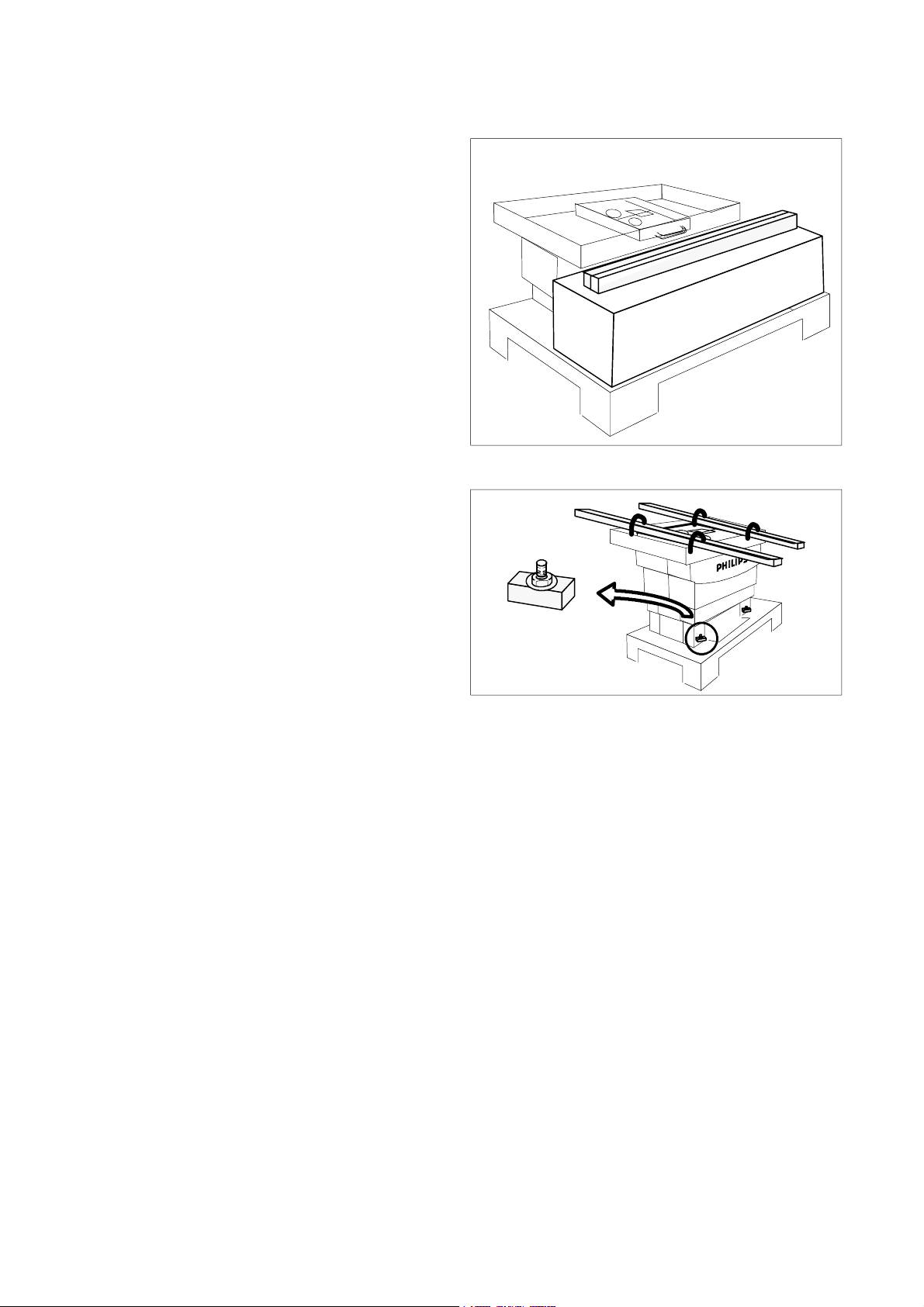
1.2. Unpack
S Remove the boxes and the wooden bars from the
pallet. The boxes include the table covers.
BuckyDiagnost TH2 / TF (MSB)INSTALLATION
S Loosen the nuts 4x of the screwings at the front
and rear side.
-- Remove the nuts.
-- Remove the washers.
-- Remove the fixing blocks.
S Insert the wooden bars into the loops.
S Lift up the table base with four persons and remove
it from the pallet.
4x
E 2005 Koninklijke Philips Electronics N.V.
ALL RIGHTS RESERVED
BuckyDiagnost TH2 / TF (MSB)CSIP Level 1 (05.0)2--2
BD_th2_TF_MSB_2_BW
Page 14

BuckyDiagnost TH2 / TF (MSB)
2. Floor fixation of BuckyDiagnost TH2/TF
Determine the working position of the table.
Note
Refer to PRD room layout or local planning data and use
the drilling template from the System Manual
Installation.
S Mark the four fixing points at the floor.
S Drill ∅12 mm holes in the middle of the marked
area about 100 mm deep.
S Insert the four anchor dowels in the holes.
S Fix the anchor dowels.
S Lift the table and place it in its working position.
3. Height adjustment for installation (TH2)
INSTALLATION
S Connect cable MEX from table to the mains of
220 VAC to move the table upwards into a better
working position.
Also connect the protection lead (green/yellow).
S Press foot switch to move the table upwards.
S Press foot switch to move the table
downwards.
Warning!
If the table does not move downwards,
press on the tabletop with 20kp. Do not
adjust the collision switch! The table
automatically stops at the middle
position.
S Disconnect MEX from mains.
4. Alignment for BuckyDiagnost TH2 /TF
S Level the table in both directions by using a spirit
level or by using the laser alignment tool, use the
spacer, if necessary (1).
4x
S Insert the fixing block (2, 4x), the special washer
and fasten the nut with a spanner.
2
1
BuckyDiagnost TH2 / TF (MSB) CSIP Level 1 (05.0) 2--3
BD_th2_TF_MSB_2_BW
E 2005 Koninklijke Philips Electronics N.V.
ALL RIGHTS RESERVED
Page 15
BuckyDiagnost TH2 / TF (MSB)INSTALLATION
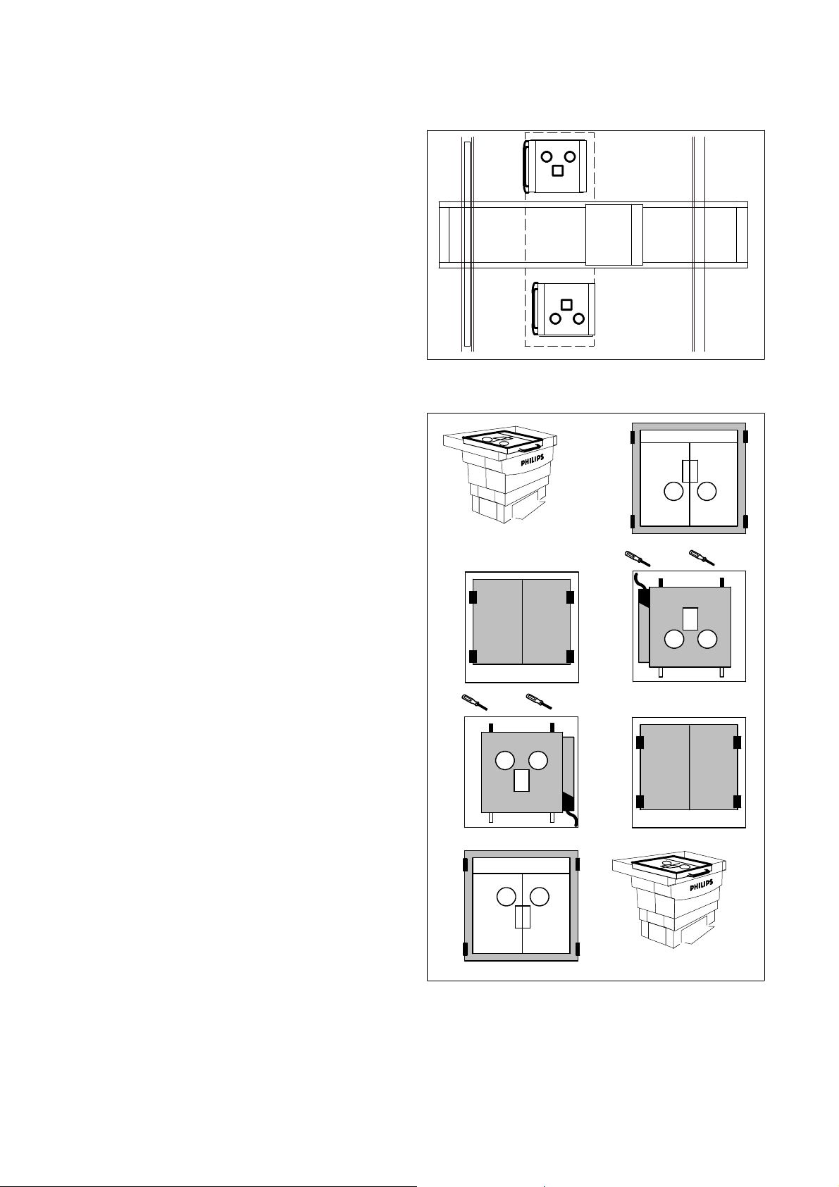
5. Change position of the AMPLIMAT chamber from left to right side
A manipulation of the connector at the AMPLIMAT
chamber is necessary, if the position of the
BuckyDiagnost TH2 / TF must be changed from left
(1) to right (2) side.
S Remove the tabletop by removing the four
screws (1).
S Mark the center line of the tabletop to the frame
(both sides).
S Remove the tabletop.
1
2
Left hand
version
Right hand
version
1
Left hand
version
1.5mm
S Dismantle the anti--scatter grid by unscrewing the
four metal holders (2).
S Remove the anti--scatter grid.
S Dismantle the AMPLIMAT chamber by loosening
the two grub screws (3).
S The wire assignment on the connector PH X1 must
be interchanged, the violett wire on X1:1 with the
black wire on X1:3.
S Place the measuring chamber at the new
position (4).
S Tighten the measuring chamber with the two grub
screws.
S Re--install the anti--scatter grid (5).
S Tighten the anti--scatter grid.
PH X1
2
4
3
5
6
Right hand
version
S Re--install the table cover at the new position (6).
S Tighten the table cover.
E 2005 Koninklijke Philips Electronics N.V.
ALL RIGHTS RESERVED
BuckyDiagnost TH2 / TF (MSB)CSIP Level 1 (05.0)2--4
BD_th2_TF_MSB_2_BW
Page 16

BuckyDiagnost TH2 / TF (MSB)
6. Electrical connection
The BuckyDiagnost TH2/TF is supplied with sets of
cables including plugs connected at one side.
S Install the cables and connect them as specified in
the corresponding SMI, Section 8, ’Cabling and
earthing’, connection diagrams.
6.1. Connection location at the
BuckyDiagnost TH2 / TF (MSB)
Power supply 230 VAC SX50 ... SX56
Power supply 24 ... 30 VDC SX40 ... SX45
Power supply TH SN1
Power supply ACL4 SN3
Bucky controller SZ1
CAN bus SZ1X2
Signal bus SZ1X1
Connection to PC ( X-Scope ) X20
Amplimat to generator SX60
Tomo CAN bus SX90
Second table control, option SAX10
Bucky brake, option SAX100
Motor amplifier board SZ2
Tomo drive and control SAN1
INSTALLATION
X2
X1
SZ1
bucky controller
X20
to service PC
Rear side
SAX10
SX50 ... SX56
SF1
SL1
SN1
SN2
VA
ACL4
4
SX40
...
SX45
SZ1
SAX100
SAN1
SX90
SX60
Front side
SZ2
BuckyDiagnost TH2 / TF (MSB) CSIP Level 1 (05.0) 2--5
BD_th2_TF_MSB_2_BW
E 2005 Koninklijke Philips Electronics N.V.
ALL RIGHTS RESERVED
Page 17

7. Installation of the tab le covers
S Raise the table to its uppermost position (only
TH2). Press foot switch to move the table
upwards.
S Lift up the foot switch assembly (1).
S Fit the lower front cover (2) into pins and screw it
on.
S Connect the earth wire SX72, SX73 to the lower
front cover.
S Fit the lower rear cover in the pins and screw it on.
S Connect the earth wire SX74 to the lower rear
cover.
BuckyDiagnost TH2 / TF (MSB)INSTALLATION
2
1
S Insert the middle side covers at both sides of the
table.
S Install both middle covers at the front and rear side.
The covers are identical.
S Insert the screws. Do not fasten the screws
completely.
S Install the upper covers at the front and the rear
side. The covers are identical. Do not fasten the
screws completely .
S Adjust the covers.
S Fasten all screws.
S Move the table up and down and check whether the
covers slide without any abrasion and noise
(only TH2).
E 2005 Koninklijke Philips Electronics N.V.
ALL RIGHTS RESERVED
BuckyDiagnost TH2 / TF (MSB)CSIP Level 1 (05.0)2--6
BD_th2_TF_MSB_2_BW
Page 18
BuckyDiagnost TH2 / TF (MSB)
8. Installation of the tabletop for BuckyDiagnost TH2/TF
S Remove the tabletop from the transport box.
S Check whether the ball bearings are adjusted
correctly to the tabletop. If not, remove the tabletop
and adjust the eccentric bearings.
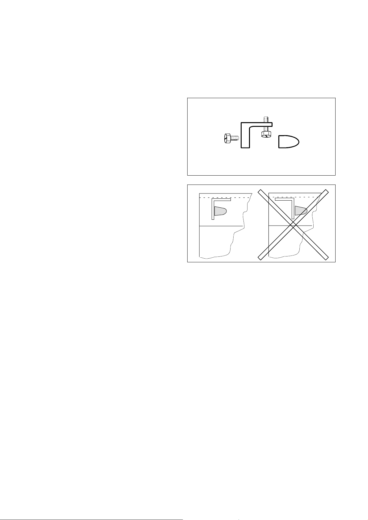
Installation of the end stops:
S Remove the parabolic buffer from the stop angle to
install the stop assembly.
S Screw the stop angle to the table rail (respect the
“right direction”).
S Screw the parabolic buffer to the stop angle.
INSTALLATION
BuckyDiagnost TH2 / TF (MSB) CSIP Level 1 (05.0) 2--7
BD_th2_TF_MSB_2_BW
E 2005 Koninklijke Philips Electronics N.V.
ALL RIGHTS RESERVED
Page 19

9. Installation of the tab le end covers
The cover profile prevents injury by sharp edges.
S Install (4x) new end covers to the four tabletop
edges.
S Check the level of the table in both directions with a
spirit level.
-- If necessary, use linings.
10. Final work
10.1. Final work for BuckyDiagnost TH2
S Check all table functions:
-- table movement upwards and downwards
switched by the foot switches
-- table movement upwards and downwards
switched by the second table control
(optional)
-- function of longitudinal and transverse
brakes.
BuckyDiagnost TH2 / TF (MSB)INSTALLATION
200 N
S Check the collision switch.
S Move the tabletop downwards.
Press foot switch to move the table
downwards.
If the table does not move downwards
press on the tabletop with 200 N.
Do not adjust the collision switch
(SS10)!
This switch is factory adjusted.
S Seal the base of the table with silicon.
S Clean all covers with a mild cleaner like soapsuds.
S Move the table to the ”preferred table height
position” (about 750 mm), the table stops
automatically.
S Place the labels so that the dotted line is in line with
lower edge of the mid cover.
Seal
750 mm
E 2005 Koninklijke Philips Electronics N.V.
ALL RIGHTS RESERVED
BuckyDiagnost TH2 / TF (MSB)CSIP Level 1 (05.0)2--8
BD_th2_TF_MSB_2_BW
Page 20

BuckyDiagnost TH2 / TF (MSB)
10.2. Final work for BuckyDiagnost TF
S Check the function of longitudinal and transverse
brakes.
S Seal the base of the table with silicon.
S Clean all covers with a mild cleaner like soapsuds.
11. Labels
S Check the labeling (see 2Z--10).
INSTALLATION
J
BuckyDiagnost TH2 / TF (MSB) CSIP Level 1 (05.0) 2--9
BD_th2_TF_MSB_2_BW
E 2005 Koninklijke Philips Electronics N.V.
ALL RIGHTS RESERVED
Page 21

BuckyDiagnost TH2 / TF (MSB)
Contents 3--0.1.......................................................
1. Faultfinding guide 3--1.................................................
2. Power supply of BuckyDiagnost TH2 / TF with ACL4 and tomo 3--2.......
2.1. Location of electrical Components 3--2....................................
3. Power-ON sequence and stand --by 3--3.................................
3.1. BuckyDiagnost TH2/TF selftest 3--3.......................................
3.2. Tomo unit (option) selftest 3--4...........................................
4. Table movement of BuckyDiagnost TH2 3--5.............................
4.1. Table switches 3--5.....................................................
4.3. Collision switch 3--6.....................................................
5. Tabletop movement 3--7...............................................
5.1. Floating table 3--7......................................................
5.2. Table carriage brakes 3--7...............................................
6. Height sensing 3--8....................................................
6.1. Table height sensor 3--8.................................................
FAULTFINDING
FAULTFINDING
TEXT
BuckyDiagnost TH2 / TF (MSB) CSIP Level 1 (05.0)
BD_th2_TF_MSB_3_inh
E 2005 Koninklijke Philips Electronics N.V.
ALL RIGHTS RESERVED
3--0.1
Page 22

FAULTFINDING
1. Faultfinding guide
BuckyDiagnost TH2 / TF (MSB)
Convention
Switch is closed = ON
Switch is open = OFF
LED / lamp illuminated = ON
LED / lamp not illuminated = OFF
YES
Switching--ON possible ?
See
Power Supply
See
Power--ON Sequence and Stand--by
Table movements possible ?
YES
See
Table Movement
Tabletop movements possible ?
YES
See
Tabletop Movement
NO
NO
NO
Bucky carriage movement possible ?
YES
See
Tomo Unit (option) Selftest
Table Height Sensing possible ?
YES
See
Height Sensing
Tomography Run possible ?
YES
See manual
System Faultfinding Guide
Tomography Run
NO
NO
NO
BuckyDiagnost TH2 / TF (MSB) CSIP Level 1 (05.0) 3--1
BD_th2_TF_MSB_3_BW
E 2005 Koninklijke Philips Electronics N.V.
ALL RIGHTS RESERVED
Page 23

BuckyDiagnost TH2 / TF (MSB)FAULTFINDING
2. Power supply of BuckyDiagnost TH2 / TF with ACL4 and tomo
Mains power of 220 VAC for
table via F1, L1 to X50 ...X56
table lift motor SNV
PCB power supply SN1 for
table control SZ2
bucky carriage, magnetic brake VAC
bucky controller SZ1
table tomo drive & control SAN1
ACL4
PCB power supply for SN2 for
automatic cassette loader ACL4
Power supply
230 VAC
F1/L1
X56
table lift motor
X50
X51
X52
X53
X54
X55
S
230 VAC
for
230 VAC
230 VAC
SZ2
X6
X14:2 X14:1
GND
SN1
26 VDC
GND(--)
26VDC(+)
VAC
GND 26 VDC
X6:2 X6:1
SZ1
SAN1
SN2
X1
X2:2 X2:1
GND
(--)
24 VDC
(+)
X3:2 X3:1
ACL4
X5
X1M X2
X100
M
SNV
X43
X42
X44
X41
X40
2.1. Location of electrical components
ACL4
SAX10
VA
4
SN1
SX50 ... SX56
Rear side
SF1
SL1
SN2
SX40
...
SX45
SZ1
SAX100
SAN1
SX60
Front side
SZ2
CSIP Level 1 (05.0)3--2
E 2005 Koninklijke Philips Electronics N.V.
ALL RIGHTS RESERVED
BuckyDiagnost TH2 / TF (MSB)
BD_th2_TF_MSB_3_BW
Page 24

FAULTFINDING
3. Power-ON sequence and stand-by
The BuckyDiagnost system runs through a selftest after
power--ON.
S Switch ON the system.
3.1. BuckyDiagnost TH2/TF selftest
S Raise the table to its uppermost position.
Press foot switch to move the table
upwards. The table stops automatically
(only TH2).
S Unscrew the service cover at the rear side, open it
for inspection.
BuckyDiagnost TH2 / TF (MSB)
S Press reset switch (1) to re-start the bucky
controller.
The red LED (2) (= bucky controller is not ready) is
illuminated until the selftest is ended successful.
The yellow LED (3) (= CAN bus is working) flashes after
successful selftest.
The green LED (4) (= bucky controller is ready) is
illuminated after successful selftest.
-- If the board SZ1 fails, replace it. Configure the
new board via program X-Scope.
SZ1 bucky
controller
2
34
1
BuckyDiagnost TH2 / TF (MSB) CSIP Level 1 (05.0) 3--3
BD_th2_TF_MSB_3_BW
E 2005 Koninklijke Philips Electronics N.V.
ALL RIGHTS RESERVED
Page 25

3.2. Tomo unit ( o p tio n) selftest
During the initialization phase the bucky carriage moves
to its tomo center position. Afterwards the bucky
carriage moves to one side then to the other side and
stops in the middle position.
If the tomo unit selftest fails:
S Check brake release switch (1) and magnetic
brake (2) on the bucky carriage.
The brake release switch is currently closed and is
mechanically opened via the grip (3).
brake
release
SACS
BuckyDiagnost TH2 / TF (MSB)FAULTFINDING
1
2
3
X8
carriage
brake
SA
VAC
SA X100
X10
SAN1
CSIP Level 1 (05.0)3--4
E 2005 Koninklijke Philips Electronics N.V.
ALL RIGHTS RESERVED
BuckyDiagnost TH2 / TF (MSB)
BD_th2_TF_MSB_3_BW
Page 26

FAULTFINDING
4. Table movement of BuckyDiagnost TH2
4.1. Table switches
S Check the function of the footswitch lock SAE.
Pressed switch = footswitches without function.
S Move the tabletop into the working position via
footswitches SC S6, S5 or via the optional second
table control SCH.
BuckyDiagnost TH2 / TF (MSB)
CH
AE
If the tabletop does not move
upwards
S Check closed 900 mm switch SNVS1 at
SZ2 X5:6/7 (24VDC) via 750 mm switch
SNVS3 at SZ2 X5:3/4.
S Check footswitch S5 for upwards movement at
SZ2 X4.
S Check optional handswitch SCH for upwards
movement at
SZ2 X9.
If the tabletop does not move
downwards
S Check closed safety switch SS10 at
SZ2 X7:2/1 (24 VDC) via closed 500 mm switch
SNVS2 at SZ2 X5:8/9 via 750 mm switch
SNVS3 at SZ2 X5:3/4.
S Check footswitch S6 for downwards movement at
SZ2 X4.
S Check optional handswitch SCH for downwards
movement at SZ2 X9.
S10
S
NVS1
NVS3
Z2
C
S
S6 S5
C
NVS2
NV
S3
Front side
S2 S1
CH
1
1
X9
1
1
X7
Z2
X4
X5
S10
If the tabletop does not move upwards or
S Check the relay K1 or K2 on board SZ2. One of the
two relays must be activated by pressing either the
footswitch or the optional handswitch.
The relay contact supplies the voltage of 230 VAC to the
motor SNV via SZ2 X3:1/:2/:3.
downwards
K7 K2
M
X3
1
K1
K3
3
Z2
X6
S
3
1
X50
230 VAC
K1 Table upwards relay
K2 Table downwards relay
K3 Start-up relay for starting capacitor.
Relay is activated over 1 s only in the upwards
starting phase.
1
230 VAC
3
SZ2X6 SNV
K1
K2
K7
K3
X3
M
BuckyDiagnost TH2 / TF (MSB) CSIP Level 1 (05.0) 3--5
BD_th2_TF_MSB_3_BW
E 2005 Koninklijke Philips Electronics N.V.
ALL RIGHTS RESERVED
Page 27

BuckyDiagnost TH2 / TF (MSB)FAULTFINDING
During movement the tabletop stops in the middle
position of the table height via the 750 mm
switch SNV S3 on the table lift motor.
S Seealsodrawing4Z--2.
4.2. Collision switch
S Check the force of the table movement.
-- Pull up the tabletop with a spring balance.
The safety switch SS10 must open if a force
of 160 ... 240 N is reached. Otherwise:
-- Adjust the spring tension at the tension screw
with a 13 mm spanner
clockwise = force of collision
decreases
counterclockwise = force of collision
increases
S
C
Z2
S6
X4
0VDC
1 ... 2 mm
Clearence of retainer
W1
+24 VDC
K2
K1
K3
K7
160 ... 240 N
K4 X5
S10
X7
X5
S3
750 mm
S2
500 mm
S1
900 mm
NV
CSIP Level 1 (05.0)3--6
E 2005 Koninklijke Philips Electronics N.V.
ALL RIGHTS RESERVED
BuckyDiagnost TH2 / TF (MSB)
BD_th2_TF_MSB_3_BW
Page 28

FAULTFINDING
5. Tabletop movement
5.1. Floating table
S Press the footswitch SC S3. The tabletop must be
floatable. If not, check items:
-- footswitch lock SAE
(must not be active = pressed)
-- brakes for longitudinal and transverse direction
-- footswitch for tabletop floating
S Use the second table control to check functions as
described above, if possible.
5.2. Table carriage brakes
S Check the function of the brakes.
BuckyDiagnost TH2 / TF (MSB)
AE
S
Z2
C
S3S3
Front side
S Check the connection to SZ2 X10. Voltage of +24 V
is delivered via the footswitch S3 or via the optional
second table control switch.
If the footswitches are locked via the footswitch
lock, functions of tabletop movements via the
optional second table control are always possible.
SD
S
SA
C
S3
CH
X9
X8
1
1
X10
SA SD SAE
SA
SD
S4
1
Z2
X4
BuckyDiagnost TH2 / TF (MSB) CSIP Level 1 (05.0) 3--7
BD_th2_TF_MSB_3_BW
E 2005 Koninklijke Philips Electronics N.V.
ALL RIGHTS RESERVED
Page 29

6. Height sensing
6.1. Table height sensor
S SeealsodrawingZ1-3.
The height sensor operates as a current source.
The range of the current value is 5 mA (table is in lowest
position) up to 18 mA (table is in uppermost position).
BuckyDiagnost TH2 / TF (MSB)FAULTFINDING
S
U
The current value can be shown :
S Connect a service PC to SZ1 X20.
S Call up program VT100 for monitoring.
S Type in:↵
-- superuser↵
-- set service output_errors_to_vt100
1↵
Every action is shown on the PC screen, also the current
depending on the topical table height.
-- show analogue↵
The analogue inputs is displayed on the PC screen.
-- show service sid↵
The SID parameters are displayed on the PC screen.
S Check the height sensor SU at SZ1 X4, measure
the current.
S
U
24 VDC
1
6
A
I = 5 ... 18 mA
U
X4
Rear
side
Z1
D1
X4
Z1
24 VDC
1
6
analog
S
-- I f I = 0 m A ,
check the voltage at X4:1 or find the reason
in the cable.
-- I f I = 2 0 m A ,
check the cable or replace the height sensor.
X20
24 V
GND
5V
Z1
J
CSIP Level 1 (05.0)3--8
E 2005 Koninklijke Philips Electronics N.V.
ALL RIGHTS RESERVED
BuckyDiagnost TH2 / TF (MSB)
BD_th2_TF_MSB_3_BW
Page 30

BuckyDiagnost TH2 / TF (MSB)
Contents 4--0.1............................................................
1. Replacement of the table lift motor at BuckyDiagnost TH2 4--1..............
1.1. Manpower 4--1............................................................
1.2. Replacement 4--1.........................................................
1.3. Final work 4--1............................................................
2. Replacement of the height sensor 4--2.....................................
REPLACEMENTS
REPLACEMENTS
BuckyDiagnost TH2 / TF (MSB) CSIP Level 1 (05.0) 4--0.1
BD_th2_TF_4_050_inh
E 2005 Koninklijke Philips Electronics N.V.
ALL RIGHTS RESERVED
Page 31

REPLACEMENTS
BuckyDiagnost TH2 / TF (MSB)
1. Replacement of the table lift motor at BuckyDiagnost TH2
1.1. Manpower
1 service engineer, approximately 2 hours.
A second person must be present on request
(e.g. to insert the safety rod).
1.2. Replacement
S Switch OFF the system.
S Remove the table covers.
S Disconnect the motor unit from the table controller
board SZ2 on X3 and X5.
If the table is in the lowest position:
S Screw the bolt (1) against the frame and lift the
frame about 1 cm so that access to the cylindrical
pin (2) is possible.
S Remove the retaining ring on the pin (2).
S Remove the cylindrical pin.
S Lift up the table assembly to insert the safety rod
through the holes (3) at the rear side and the front
side.
(The safety rod is placed near the safety label on
the frame.)
2h
Rear side
Replacement of the
table lift motor
Handing over
Z2
S
2
1
on request
X5
X3
3
S Remove the retaining ring on the cylindrical pin (4).
S Remove the cylindrical pin.
S Replace the table lift motor.
S Re-assemble the table.
S Park the safety rod.
1.3. Final work
S Test all movements of the table.
BuckyDiagnost TH2 / TF (MSB) CSIP Level 1 (05.0)
BD_th2_TF_MSB_4
E 2005 Koninklijke Philips Electronics N.V.
ALL RIGHTS RESERVED
Front side
4
SZ2
4--1
Page 32

2. Replacement of the height sensor
S Raise the bucky tabletop to its uppermost position.
S Loosen the two screws on the housing.
S Replace the height sensor unit.
S Assemble in reverse order.
BuckyDiagnost TH2 / TF (MSB)Replacements
U
J
CSIP Level 1 (05.0)4--2
E 2005 Koninklijke Philips Electronics N.V.
ALL RIGHTS RESERVED
BuckyDiagnost TH2 / TF (MSB)
BD_th2_TF_MSB_4
Page 33

BuckyDiagnost TH2 / TF (MSB)
Contents 6--0.1............................................................
1. Delay time check by test exposures 6--1...................................
1.1. Cassette loader INALFA 6--1................................................
1.2. Cassette loader ACL4 6--1..................................................
2. Tomography (option) 6--2.................................................
2.1. Adjustment of tomo force 6--2...............................................
2.2. Tomo exposure 6--2........................................................
ADJUSTMENTS
ADJUSTMENTS
BuckyDiagnost TH2 / TF (MSB) CSIP Level 1 (05.0)
BD_th2_TF_MSB_6_inh
© 2005 Koninklijke Philips Electronics N.V.
ALL RIGHTS RESERVED
6--0.1
Page 34

BuckyDiagnost TH2 / TF (MSB)
1. Delay time check by test exposu res
To adjust the exposure delay time preparatory work is
necessary.
S Remove the tabletop to have free access to the
anti-scatter grid of the bucky table .
S Check the delay time with a test exposure.
-- Lay the lead plate (1) on the grid (2), fix it with a
piece of adhesive tape.
-- Make two exposures (see table) on the same
film.
The exposure shows a spot and a bar (3).
ADJUSTMENTS
2
1
anti-scatter grid motion
after exposure release
Exposure Exposure
time
[sec]
1 0.5 60 15 0.6
2 0.02 125 25 0.6
[kV] [mA] Focus
S Measure the distance as shown in (3).
1.1. Cassette loader INALFA
S See manual of INALFA.
1.2. Cassette loader ACL4
S See manual of ACL4.
[mm]
3
8 ... 10 mm
BuckyDiagnost TH2 / TF (MSB) CSIP Level 1 (05.0) 6--1
BD_th2_TF_MSB_6_BW
E 2005 Koninklijke Philips Electronics N.V.
ALL RIGHTS RESERVED
Page 35

2. Tomography (option)
2.1. Adjustment of tomo force
S Move the tabletop to its height center position.
If the tomography function is established, the
bucky unit centers itself after power--ON.
BuckyDiagnost TH2 / TF (MSB)ADJUSTMENTS
1
S Switch OFF the system.
S Insert a spring scale in the handle (1).
-- Pull with the spring balance.
The value of force is <10 N.
S Switch ON the system.
S Insert a spring scale in the handle (1).
-- Pull with the spring balance.
The value of force is <5 N for a system with
servo.
As necessary, loosen or tighten the belt via both
screws (2) by loosening the nut (3) after removing the
tabletop.
S Check the tomo force as described above.
If the belt oscillates it must be tensioned.
The tray servo assistance can be defined, see
documentation of program X-Scope, Tomography
configuration, ’Tray servo assistance’.
<5 N = System without belt
<10 N = System with belt
<5 N = System ON & Servo
3
2
2.2. Tomo exposure
For programming tomo run direction see manual
X-Scope.
E 2005 Koninklijke Philips Electronics N.V.
ALL RIGHTS RESERVED
J
BuckyDiagnost TH2 / TF (MSB)CSIP Level 1 (05.0)6--2
BD_th2_TF_MSB_6_BW
Page 36

Drawings
BuckyDiagnost TH2, Mechanical dimensions Z--1.1
BuckyDiagnost TF, Mechanical dimensions Z--1.2
Labelling 2Z--10
Section ZBuckyDiagnost TH2 / TF (MSB)
BuckyDiagnost TH2 / TF (MSB) CSIP Level 1 (05.0) Z--0.1
BD_z01
E 2005 Koninklijke Philips Electronics N.V.
ALL RIGHTS RESERVED
Page 37

Page 38

Page 39

Bucky unit 2 digital
Y
Table height adjustable
W
X
Logo
Table top
Address
Barcode
UL/CSA
Type No.
Logo
Bucky unit 2 digital
Z
Logo
Type No.
UL/CSA
Barcode
Table top
Logo
Type No.
IEC 60601-1
UL / CSA
CE
Address
Electr. data
IEC 60601-2-32
Type No.
FDA
Y
X
Z
PHILIPS
A1/A3 04-10-05 Schr.
W+Z
BuckyDiagnost TH (BUF)
Labelling
4512 983 05451
C Philips Medical Systems
(e/04.0)
2Z-10
Page 40

Schematic diagrams
Wiring diagrams
BuckyDiagnost TH2/TF MSB Survey of components Z1--1
BuckyDiagnost TH2/TF (MSB) with Inalfa sensing Internal connection diagram Z1--1.2
BuckyDiagnost TH2/TF (MSB) with ACL4 Internal connection diagram Z1--1.3
BuckyDiagnost TH2/TF (MSB) with Inalfa non sensing Internal connection diagram Z1--1.4
BuckyDiagnost TH2/TF (MSB) Power supply Z1--2
BuckyDiagnost TH2/TF (MSB) Safety circuit and brakes Z1--3
BuckyDiagnost TH2/TF (MSB) CAN and MSB bus Z1--5
BuckyDiagnost TH2/TF (MSB) Wiring diagram Z2--1
BuckyDiagnost TH2/TF (MSB) Earthing diagram Z2--3
Tomo drive control survey of components Z2--4
Section ZBuckyDiagnost TH2 / TF (MSB)
IIFmainTH Z3--1.1
IIFmainTH Z3--1.2
AI IF carriage Z3--2.1
AI IF carriage Z3--2.2
Z1 Bucky controller (4512 108 07508) Z3--3.1
Z1 Bucky controller (4512 108 07508) Z3--3.2
SZ1 Table control Z3--4.1
BuckyDiagnost TH2 / TF (MSB) CSIP Level 1 (05.0) Z--0.2
BD_z02
E 2005 Koninklijke Philips Electronics N.V.
ALL RIGHTS RESERVED
Page 41

Top view
A - B
A
C
SAE
SA SAVA
PHILIPS
SC
SNVS1..3
SNVM
B
D
SAPCB
SACH
SA
SACH
SAE
SAI
SAN
SAS1
SAVA
SAY1+2
SAY20+21
SAY31
SC
SF1
SI
SL1
SNVM
SNVS1...3
SN1
SN3
SU
SZ1
SZ2
A3 05-01-25 Schr.
=
Transverse carriage
=
Second table control (option)
=
Footswitch lock
=
IF Carriage board
=
Tomo control (option)
=
Switch Bucky frame brake
=
Bucky unit
=
Logitudinal brakes
=
Transversal brakes
=
Bucky frame brake
=
Footswitch
=
Motor protection switch
=
IF Main board TH
=
Mains filter 1
=
Table height motor
=
Motor control switches
=
Power supply 20,4VAC
=
Power supply 24VAC (ACL4 only)
=
Height Poti
=
Bucky controller
=
Table control
for DigitalDiagnost TH (BUF) only
SAPCB
SL2
SN2
STSN1
STSN2
=
Pixium control board
=
Mains filter 2
=
Power supply 24VDC
=
Power supply 9.26 V AC
=
Power supply 9.26 V AC
STSN1
SU
SAY1
SAY21
SZ1 SI
STSN2
SN3
SZ2
SAI
SN2
SAS1
Top view
SN1
Front
Front
C - D
SL2
SAN
SAY31
SF1
DigitalDiagnost TH (BUF)
BuckyDiagnost TH2 (MSB)
SL1
SC
Survey of components
SAY20
SNVM
SNVS1..3
SAY2
DigitalDiagnost TH
C Philips Medical Systems
Z1-1(a/05.0)
Page 42

EZX21
Generator
X60
Intermediate
Connector
Transversal Carriage
A
S1
Switch
Y31
Brake f. Bucky
Frame
E
Encoder
X5
Motor
X2
M
X1
Power
N1
(Option)
CAN in
X3
Tomo
X8
X10
X1
Amplimat Chamber
PH
Long. Brake
left
Transv. Brake
left
Long. Brake
right
Y20Y2Y21Y1
Transv. Brake
right
CH Handswitch
(Option)
E
(Option)
Footswitch
Lock
VA
Bucky Unit (Inalfa)
Signal-Bus
CAN out
EZX23
EZX43
I
230 VAC in
20,4 VAC out
N1 Power Supply
20,4VAC
X1X6
IF Carriage
X51
X39
YX21
Connector
X3
X2
X52
X7
X5
X4
X1
MSB / Power
I IF Main TH
X4
X54
X41
X50
X300
X55
X40
X3
X2
X90
X5
only for BuckyDiagnost VS
Release
X1
Signal-Bus
X1
CAN in
X2
Grid Control
X13
CAN out
X3
26Vdc in
X6
sensing BWS
release BWS/
grid control
X12 X10 X11 X5
Sensing
position BWS
X100
X2
gender
changer
X9
Sensing
Z1 Bucky Controller
remoteX8safety Tomo
tracking BWS
X7
X4
X20
YX20
Connector
MEXT1/T2/N
Generator
BuckyDiagnost VS
BuckyDiagnost VS
BuckyDiagnost
VE/VT
VPIX10
VPIX7
VPX1
VP1X2
VP1X3
VP1X5
A1/A3 05-01-26 Schr.
BuckyDiagnost TH2 TF
C Philips Medical Systems
Power Supply Unit
F1
L
Mains Switch
T
AE
Line
L1
Load
Mains Filter
F
X6
X14
26VDC in
230VAC in
Safety Circle
X7 X4 X1
S10
Safety Switch
Footswitch
C Footswitch
Z2Table Control
C1/C2
Start-/Operation-
Capacitor
Safety Tomo out
X11
X3
X5
M
Motor
S1 (Height switch upper position)
X13
X12
Remote
light tr.
Safety
Brakes
X10
Handswitch
X9
Footswitch Lock
X8
NV Table Drive
Z1X20.1
UBN2X3 / UAX1 / UADX3
Ceiling Suspension
UL1
Ceiling Suspension
U
Tomo in
SID-Poti
Service
Interface
Ceiling Suspension
UBN1X4
BuckyDiagnost TH2 (MSB)
with Inalfa sensing
Internal connection diagram
S2 (Height switch lower position)
Table
S
S3 (Height switch middle position)
Z1-1.2(05.0)
Page 43

EZX21
Generator
X60
Intermediate
Connector
Transversal Carriage
A
S1
Switch
Y31
Brake f. Bucky
Frame
E
Encoder
X5
Motor
X2
M
X1
Power
N1
(Option)
CAN in
X3
Tomo
X8
X10
VA
X1
Amplimat Chamber
PH
ACL4
Long. Brake
left
Transv. Brake
left
Long. Brake
right
Y20Y2Y21Y1
Transv. Brake
right
CH Handswitch
(Option)
E
(Option)
Footswitch
Lock
Signal-Bus
CAN out
EZX23
EZX43
I
N3 Power Supply
24VAC (ACL 4)
230 VAC in
24 VAC out
230 VAC in
20,4 VAC out
N1 Power Supply
20,4VAC
X1X6
IF Carriage
X53
X38
X51
X39
Intermediate
X50
Connector
X300
Intermediate
Connector
X200
X55
X40
X3
X2
X90
Release
X5
only for BuckyDiagnost VS
X3
X2
X7
X4
X5
X101
Intermediate
Connector
X1
X37
MSB / Power
I IF Main TH
X4
X41
X52
X54
X2
Release
X3
Power
Signal-Bus
X1
CAN in
X2
Grid Control
X13
CAN out
X3
26VDC in
X6
position BWS
sensing BWS
release BWS/
grid control
X12 X10 X11 X5
X100
remoteX8safety Tomo
tracking BWS
X7
YX21
Connector
X9
sensing
Z1 Bucky Controller
X4
X20
YX20
Connector
MEXT1/T2/N
Generator
BuckyDiagnost VS
BuckyDiagnost VS
BuckyDiagnost
VE/VT
VPIX10
VPIX7
VPX1
VP1X2
VP1X3
VP1X5
A1/A3 05-01-26 Schr.
BuckyDiagnost TH2 TF
C Philips Medical Systems
Power Supply Unit
F1
L
Mains Switch
T
AE
Line
L1
Load
Mains Filter
F
X6
X14
26VDC in
230VAC in
Safety Circle
X7 X4 X1
S10
Safety Switch
Footswitch
C Footswitch
Z2Table Control
C1/C2
Start-/Operation-
Capacitor
Safety Tomo out
X11
X3
X5
M
Motor
S1 (Height switch upper position)
X13
X12
Remote
light tr.
Safety
Brakes
X10
Handswitch
X9
Footswitch Lock
X8
NV Table Drive
D 25p.
Z1X20.1
Ceiling Suspension
UBN2X3
Ceiling Suspension
UL1
U
Tomo in
SID-Poti
Service
Interface
UBN1X4
Ceiling Suspension
BuckyDiagnost TH2 (MSB)
with ACL 4
Internal connection diagram
S2 (Height switch lower position)
Table
S
S3 (Height switch middle position)
Z1-1.3(05.0)
Page 44

EZX21
Generator
X60
Intermediate
Connector
Transversal Carriage
A
S1
Switch
Y31
Brake f. Bucky
Frame
X6
Intermediate
connector
Amplimat Chamber
PH
X1
VA
Bucky Unit (Inalfa)
Long. Brake
left
Transv. Brake
left
Long. Brake
right
Y20Y2Y21Y1
Transv. Brake
right
CH Handswitch
(Option)
E
(Option)
Footswitch
Lock
WAX1
Generator
I
230 VAC in
20,4 VAC out
N1 Power Supply
20,4VAC
X1X6 X2
IF Carriage
X51
X39
YX21
Connector
X3
X52
X7
X5
X4
X1
MSB / Power
I IF Main TH
X4
X54
X41
Intermediate
connector
X50
X300
X55
X40
X3
X2
X90
Release
X1
X5
YX20
Connector
MEXT1/T2/N
Generator
A1/A3 05-01-26 Schr.
BuckyDiagnost TH2 TF
C Philips Medical Systems
Power Supply Unit
F1
L
Mains Switch
T
AE
Line
L1
Load
Mains Filter
F
X6
X14
26VDC in
230VAC in
Safety Circle
X7 X4 X1
S10
Safety Switch
Footswitch
C Footswitch
Z2Table Control
C1/C2
Start-/Operation-
Capacitor
Safety Tomo out
X11
X3
X5
M
Motor
S1 (Height switch upper position)
X13
X12
Remote
light tr.
Safety
Brakes
X10
Handswitch
X9
Footswitch Lock
X8
NV Table Drive
UBN2X3 / UAX1 / UADX3
Ceiling Suspension
UL1
Tomo in
UBN1X4
Ceiling Suspension
Ceiling Suspension
BuckyDiagnost TH2 (MSB)
with Inalfa non sensing
Internal connection diagram
S2 (Height switch lower position)
Table
S
S3 (Height switch middle position)
Z1-1.4(05.0)
Page 45

S
Table
SA
Transverse
carriage
SAVA
Bucky unit
SF1
L1
N
230VAC Generator
SL1
Mains
filter
L1
N
X52:1
X52:3
X53:1
X53:3
X51:1
X51:3
Main interface
SI
X50:1
X50:3
X54:1
X54:3
L1
L1
N
N
L1
N
L1
N
in
SN3
24V AC
(ACL4)
230V AC
0V AC
SN1
230V AC
20,4V AC
0V AC
VPX7 BuckyDiagnost VS
in
out
out
24V AC
0V AC
20,4V AC
0V AC
X38:1
X38:3
X39:1
X39:2
SX101
X37:1
X37:4
X40:1
X40:2
X1:4 X5:4
X1:15
X1:8
X41:1
X41:2
24V AC
24V GND
26V DC
26V GND
26V DC
26V GND
26V DC
26V GND
L1
N
1
2
X6:1
X6:2
X14:1
X14:2
X6:1
X6:3
SZ1
Bucky
controller
SZ2
Table
control
SA X200
X5:15
X5:8
8
9
SAI
Interface
carriage
X4:15
X4:8
SA
X300
15 8
or
or
X3
1
2
X1
X1
1
5
X1
15
2
ACL4
1
5
Inalfa
Bucky
unit 2
A3 05-01-26 Schr.
BuckyDiagnost TH2 TF
C Philips Medical Systems
(05.0)
X55:1
X55:3
L1
N
UZX9 Ceiling suspension
BuckyDiagnost TH2 (MSB)
Power supply
Z1-2
Page 46

Transverse carriage
SIX1:4
X8:3
X8:4
X8:5
X4:3
X4:4
X9:3
X9:4
X20:19
K8
K8
161
K81
161
brakes
2
S3
1
4
SACH
Handswitch
SAE
Footswitch
lock
(option)
lock
S1
H1
S3
2
1
brakes
S4
2
1
SC
Footswitch
(option)
X9:5
X4:5
S6
2
S6
S5
S5
down
1
4
2
up
1
4
SIX41:1
26V
SIX41:2
0V
SIX50:1
L
230V~
SIX50:3
N
2
down
1
4
2
up
1
4
X4:7
X9:7
X4:6
X9:6
X4:8
X9:8
X14:1
X14:2
X6:1
X6:3
X20:17
0V
X20:3
X20:4
X20:1
X20:2
lock
K81
0V
64
+26V
0V
A1/A3 05-01-26 Schr.
bucky controller
SZ1X8
X12:1
X12:2
lock
X20:16
X20:15
+26V
0V
+26V
0V
0V
0V
0V
0V
SZ2
Table control
control/
delay
B2
B1
X20:05
U1
X20:06
H5
+15V+26V
test
B4
B3
D1A
D1B
K4
safety tomo
48
X20
collimator light
0V
0V
+26V
16
1
safety servo
100R
R2
X20:12
+15V
+15V
H2
H1
start-up
16
down
2K21
R32
up
2K21
R31
K2
K1
K3
1
12
12
12
H3
K7
ED
12
H4
4
up
K1
4
5
3
down
K2
R100
collimator light
X20:22 X20:21
X20:08X20:07
K5
K6
X20:11
470µ
C2
K4
safety tomo
X20:10
X20:13
X20:09
ED
K7
3
K3
start-up
R1
4K7
K5
64
K4
43
5
1
16
+26V
+26V
X10:1
X10:2
X5:3
9
13
X5:4
X5:5
X7:1
+24V
0V
X7:2
X5:8
X5:9
X5:6
X5:7
X3:4
X3:5
X3:3
X1:1
3
X1:3
4
1M
X1:4
X1:2
X3:1
X3:2
X13:1
X13:2
X11:1
X11:2
collimator
Tomo safety circuit CS
+26V
SX120:15
SX120:4
SIX1:15
SIX1:8
0V
only if DigitalDiagnost VM
X5:4
X5:15
X5:8
YX20:1
YX20:2
A1
Collisions
A2
switch VM
C1C2
SA
X6:1
IF Carriage
I
W1
transverse brakes longitudinal brakes
++
SK1
1
2
11
14
2
SS10
safety switch
1
X6:3
X7:1
X7:3
X1:1
X1:2
YX21:1
YX21:2
2
S1
1
+
Y31
-
+
--
+
750mm
1
S3
24
500mm
21
S2
900mm
21
S1
X8:1
X10:1
-
N1
+26V
Y2 Y1Y20 Y21
right leftright left
Tomo control
0V
in
out
out
-
SNV
Motor
control
switches
P2
P1
L2
K3
M
L1
N
DigitalDiagnost TH (BUF)
BuckyDiagnost TH2 (MSB)
Safety circuit and brakes
DigitalDiagnost TH
C 1999 Philips Medical Systems
ALL RIGHTS RESERVED
(d/05.0)
Z1-3
Page 47

CAN
bus
SZ1
Bucky controller IF Main TH
X2
1
2
3
4
5
X3
1
6
7
8
9
6
2
7
3
8
4
9
5
CAN out
X2
1
2
3
4
5
6
7
8
9
SI
X90
1
6
2
7
3
8
4
9
5
CAN to CS
SAI
IF Carriage
X3 X3
6
7
8
9
male
1
2
3
4
5
CAN
1
2
3
4
5
female
6
7
8
9
SZN1
Motor control
Tomo
r
o
t
a
r
e
n
e
G
m
o
r
f
Signal
bus
female
X1
1
14
2
15
3
16
4
17
5
18
6
19
7
20
8
21
9
22
10
23
11
24
12
25
13
male
A
Driver
SZ1 SI
male female
X13
1
6
2
7
3
8
4
9
5
female
X12 X5
1
6
2
7
3
8
4
9
5
female
SAVA
PHILIPS
Top view
A - B
Grid control
BUF table
Grid control
BWS
X3
6
7
8
9
male
6
7
8
9
male
male
X1
1
9
2
1
2
3
4
5
10
3
11
4
12
5
13
6
14
7
15
8
male
MSB MSB
X5
9
10
11
12
13
14
15
male
X4
1
2
3
4
5
6
7
8
9
10
11
12
13
14
15
male
1
2
3
4
5
6
7
8
X1
9
10
11
12
13
14
15
male
1
2
3
4
5
6
7
8
X16
1
3
5
7
9
11
13
15
2
4
6
8
10
12
14
16
CAN control
Release
circuit
control
X4
1
9
2
10
1
2
3
4
5
3
11
4
12
5
13
6
14
7
15
8
MSB to BWS
SAVA
male
B
MSB Signal Pin connector
CAN GND
CAN L in
CAN L out
not used
not used
sync grid GND
sync grid
26V DC GND
CAN 15V
CAN H in
CAN H out
not used
start grid
start grid GND
26V DC
1
2
3
4
5
6
7
8
9
10
11
12
13
14
15
1
9
2
10
3
11
4
12
5
13
6
14
7
15
8
CAN Signal Pin connector
not used
CAN L
CAN GND
not used
not used
CAN GND
CAN H
SW reset CAN
CAN 15V
BUF
1
2
3
4
5
6
7
8
9
1
6
2
7
3
8
4
9
5
A3 05-01-26 Schr.
DigitalDiagnost TH
C Philips Medical Systems
SZ1
SI
SAI
SZN1
DigitalDiagnost TH (BUF)
BuckyDiagnost TH2 (MSB)
CAN + MSB bus
Front
Z1-5(05.0)
Page 48

SZ2X8:4
+
SAYX21:1
SIX41:1
SIX41:2
SZ1X7:1
SZ1X7:2
SZ1X8:1
SZ1X8:2
UBN1X4:5
UBN1X4:6
SAYX20:1
SAYX20:2
SAYX21:2
SAE1 (option)
3
1
ba
2
4
SZ2X8:3
SZ2X8:5
12
12
3 124
3 124
12
X10
X14
X13
SAY21SAY1
SAIX1:2
SAIX6:1
SAY31
SAIX6:3
2 1
1
4
2
SACH handswitch
SAIX1:1
SAS1
VA
Bucky unit
+--
SAYX21:1
SAYX21:2
SAYX21 SAYX20
SAY1:+
SAY1:-
01
02
SAY21:+
SAYX20:1
SAY21:SAYX20:2
35 4
9 8127 6
(option)
35 4
9 8127 6
X8
SAE footswitch lock
(option)
SA
Transverse carriage
AMPLIMAT
X20 TEST
1
PHX1
SNVS2:1
SNVS3:2
SCS5:4
SCS6:4
SCS3:1
SCS5:1
SCS4:2
SCS6:2
DOWNUP
H2H1
35 4
9 8127 6
SNVS2:2
SNVS3:4
9 8127 6
SX60
SNVS1:1
SNVS1:2
SNVS3:1
35 4
X5X4X9
X12
START UPED
SN1VM1:L1
SNV1M1:N
SNV1M1:L2
X3
1254
3 6
SNV1F1:P2
SNV1F1:P1
X1
3 124
C1
C1
C2
C2
X11
X6
X7
3 12
12
SS10:2
SS10:1
SIX50:1
SIX50:3
H5 H3H4
15V
SZ2
Table control
SZ2X10:1
SAYX21:1
SZ2X10:2
SAYX21:2
SS10
SAY2SAY20
SZ2X9:4
-
+
SAYX20:1
SAYX20:2
+-
SAYX20:1
SAYX20:2
SZ2X9:3
S3
1
4
2
SACH
SAY20:+
01
SAY2:+
SAY20:-
02
SAY2:-
SZ2X5:6
1
S1
4
SZ2X5:7
2
SZ2X7:2
1
4
SZ2X7:1
2
SZ2X5:4
2
SZ2X5:5
4
SZ2X5:3
S3
1
SZ2X9:5
S5:2
S6:1
SZ2X9:8
(option)
S6
2
4
1
S5
2
4
1
F1:6/T3
SX70
F1:2/T1
L1:1
SIX52:2
L1:2
NO NC
2/T1
4/T2
6/T3
2
5 LINE
1
S4:1
SZ2X3:3
1
4
2
SZ2X4:7
SZ2X4:5
1
4
2
SC
SZ2X4:6
S6:1
SZ2X4:8S5:2
1
4
2
SZ2X4:4
S3:2
1
4
2
Foot switch
SZ2X5:9
2
4
SZ2X5:8
S2
1
SZ2X1:3
SZ2X1:4
SZ2X1:1
SZ2X1:2
C2
C1
SF1
2214
01
SL1
21 13
NC NO
LOAD
1/L1
3/L2
5/L3
MEX (L1)
SNV
MEX (N)
SZ2X3:4
P2
SZ2X3:5
P1
SZ2X3:3
L2
SZ2X3:1
SZ2X3:2
F1
SN3
Power
supply
for ACL4
1.0A slow 250V
3,15A slow
250V
F2
24VAC
SIX38:1
0V
SIX38:2
SN1
Power
F1
supply
5,0A slow 250V
1.0A slow 250V
switched
SIX52:3
4
SIX52:1
3
SIX51:1
SIX51:3
230V AC
L
N
F2
0V
20,4VAC
SIX39:1
SIX39:2
SIX53:1
SIX53:3
230V AC
L
N
M1/F1
L1
N
Motor
A1/A3 05-01-26 Schr.
BuckyDiagnost TH2 TF
C Philips Medical Systems
ALL RIGHTS RESERVED
BuckyDiagnost TH2 (MSB)
Wiring diagram
Z2-1(05.0)
Page 49

Potential
X80
A
Balance
Transversal
Carriage
YX14
YX13
(SAY)X11
Y31
Brake f.
Bucky Frame
(SAVAX11
Bucky Unit)
X12
X11
(SAY)X12
CH
Handswitch
E
Footswitch Lock
Y1
Long.
Brake
right
X2
screw
Powe supply
20,4 Vac
F1
N1
Mains Switch
screw
X1
screw
L1
Mains Filter
IF Main TH
I
Sheet Power Supply Unit
Y21
Transv.
Brake left
Sheet Bucky Carriage
X80
X71
I
IF Carriage
Release Bar
S1
Switch
YX12
Y20
Transv.
Brake right
Transversal Carriage
screw
Y2
Long.
Brake
right
X1
S
X2
Table
X72
X73
X11
X11
X12
X13
BuckyDiagnost TH2 (MSB)
S10
Safety switch
Sheet Table Control
Z2
C
Table control
screw
X11
Footswitch
A1/A3 05-01-26 Schr.
C1 / C2
Start- /Operationcapacitor
Lower Cover Front
Lower Cover Rear
Service Cover
Motor
M
S1
S2
S3
NV
(Height switch upper position)
(Height switch lower position)
(Height switch middle position)
X74
Table drive
Earthing diagram
BuckyDiagnost TH2 TF
C Philips Medical Systems
Z2-3(05.0)
Page 50

SAN1
Tomo drive control
rd FAILURE
yw INK_B
yw INK_A
gn RUN
gn REF
LEDs on
soldering side
yw P_1.1
gn P_1.2
LEDs on
soldering side
P_1.0
U1
M1
X5
X2
SAI X2
U1
+24VDC
0VDC
+24VMOT
0VMOT
X5X6
Encoder
X7
Jumper
GAL 66.952
GAL 66.953
IC2
IC4
EPROM
Motorcontroller
IC9
EPROM
CAN program
IC13
GAL 66.954
IC16
LEDs on
soldering side
ST8
1
X8
switchbrake
SAI X7
IC18
insolation plate
X6 X5
ST4
gn REF
gn RUN
yw INK_A
X7
yw INK_B
1
rd FAILURE
LEDs on
soldering side
IC3
ST4
ST6
1
ST7
1
X10 X9 X8
ST5
ST5
1
X9X10
reference switch
SAI X7
SW1
X1X2
X1
CAN INCAN OUT
SAI X3
ST3
A1/A3 05-01-26 Schr.
DigitalDiagnost TH
C Philips Medical Systems
ALL RIGHTS RESERVED
M1
Motor Power supply
X2
X4 X3
X4 X3
Tomo drive control
Survey of components
Z2-4(a/05.0)
Page 51

X53
2
1
3
R4 R5
W1
W11
21
21
X2
1
6
5
CAN
9
in
Power in
X50
1
X51
1
X52
1
X54
1
X55
1
230V
X1
21
21
1
9
5
9
2
3
D1
2
3
D2
W44
W4
X3
8
15
MSB
Bucky unit table
1
Grid control
Bucky unit table
6
X41
1
2
3
X40
1
8
15 9
X38
2
3
1
X4
1
MSB wallstand
X5
5
9
1
6
Grid control
wallstand
X37
2
3
31
6
4
X39
1
2
X90
5
9
CAN
1
out
6
D1 = +26 VDC
D2 = +26 MSB
R4 +R5 = Multi fuses (1,85A)
A4 04-11-23 Schr.
DigitalDiagnost TH
C Philips Medical Systems
Jumper:
W1 + W11 present if connector SIX1 is not used
not present if connector SIX1 is used
W4 + W44 present if connector SIX4 is not used
not present if connector SIX4 is used
I
IF Main TH
4512 131 3864.
Z3-1.1(04.1)
Page 52

Jumper: W1 + W11
Present if connector SIX1 is not used
X2 X1
1
1
2
3
3
4
4
5
5
6
6
7
7
8
8
9
9
CAN in
not present if connector SIX1 is used
CAN L
CAN GND
CAN GND
CAN H
SW reset CAN
CAN 15V
W1
2
1
W11
2
1
CAN L in
CAN H in
10
11
12
13
14
15
1
CAN GND
2
3
CAN L out
4
26V DC
5
free exp. 1
6
sync grid GND
7
sync grid
8
26V DC GND
CAN 15V
9
CAN H out
free exp. 2
start grid
start grid GND
26V DC
X3
1
1
2
3
3
start grid GND
4
4
5
5
start grid
6
6
7
7
8
8
9
9
Grid control
Bucky unit table
X4
1
CAN GND
2
CAN L in
3
CAN L out
4
free exp.BWS 1
5
6
sync grid GND
7
sync grid
8
9
10
CAN H in
11
CAN H out
12
free exp.BWS 2
13
start grid
start grid GND
14
15
Jumper: W4 + W44
present if connector SIX4 is not used
not present if connector SIX4 is used
W4
1
2
W44
1
2
X5 X90
1
1
2
2
3
3
4
4
start grid GND
5
5
6
6
start grid
7
7
8
8
9
9
Grid control
Wallstand
1
1
2
2
3
3
4
4
5
5
6
6
7
7
8
8
9
9
CAN out
CAN L
CAN GND
CAN GND
CAN H
SW reset CAN
CAN 15VCAN 15V
X39
2
1
VACP
VACN
C1
B1
B2
R1
C2
MSB
Bucky unit table
C3
C4
R4
2
1,85A
Multi fuse
R5
2
1,85A
Multi fuse
+26V
1
1
26V MSB
R2
R3
D1
D2
GND
MSB
Wallstand
C5
X6
X7
screen
VACP
VACN
X40
2
1
X38
1
2
3
+26V
GND
X37
1
2
3
4
5
6
X41
2
1
24V
screen
GND 24V
screen
A3 05-01-26 Schr.
DigitalDiagnost TH
C Philips Medical Systems
230V
X52
1
2
3
continious power
switched power
X51
1
2
3
X53
1
2
3
X50
1
2
3
X54
1
1
2
2
3
3
X55
1
1
2
2
3
3
I
IF Main TH
4512 131 3864.
Z3-1.2(05.0)
Page 53

MSB
Bucky
unit table
CAN
Tomo
Brake
control
Tomo
Power
Tomo
8
15
15
8
MSB
IF Main TH
X4
X5
1
9
9
1
1
X3
5
1
9
6
X1
1
Brake for
Bucky frame
X7
2
4
X6
Switch
for brake
1
3
1
X2
13
46
W1
W1- present without Tomo option
W1- not present with Tomo option
A4 04-11-23 Schr.
DigitalDiagnostTH
C Philips Medical Systems
AI
IF Carriage
4512 131 3863.
Z3-2.1(04.1)
Page 54

X5
1
CAN GND
2
CAN L in
3
CAN L out
4
26V DC
5
free exp. 1
6
sync grid GND
7
sync grid
8
26V DC GND
9
CAN 15V
10
CAN H in
11
CAN H out
12
free exp. 2
13
start grid
14
start grid GND
15
26V DC
26V DC
X4
1
2
3
4
5
6
7
8
9
10
11
12
13
14
15
CAN GND
CAN L in
CAN H in
CAN 15V
X3
1
1
2
3
3
4
4
5
5
6
6
7
7
8
8
9
9
Tomo
Controller
Power
Tomo
IF Main TH
X2
1
2
3
4
5
6
26V DC
C2
GND
GND
BUF MSB
Tomo
off
GND
W1
1
2
26V DC
X1
2
1
X6
1
2
3
X7:1
X7:2
X7:3
- Brake
+ Brake
switch
brake
Tomo
controller
A4 04-11-23 Schr.
DigitalDiagnost TH
C Philips Medical Systems
X7:4
GND
AI
IF Carriage
4512 131 3863.
Z3-2.2(04.1)
Page 55

X2
1 2
6
3 54
X21
3 54
9
7
8
1 2
6
8
9
7
6
7 8
9
21
3
X9
4
5
D2
X3
X1
X5
76
1 2
14315
21
21 3 4X45
6
7 8
21
3 54
16
3
4
4
98
17
5 6187198209
9876
9
5
21
22102311241225
1)
Address
decoder
13
D8
Firmware
version
1
HIGH -Byte
6
7 8
9
3 4
21
6
7 8
21
3
X10
5
9
X11
4
5
D5
W4
LOW -Byte
2)
1 2
6
1 2
6
7
7
3 54
3 54
8
8
X12
9
X13
9
VT-100
CAN Slave
Room 2
O
P
E
N
8
7
6
5
4
3
2
1
X-SC OPE
CAN Master
Room 1
S1
SZ1 / VSZ1
Watch dog
Bucky controller
Battery
W2
ON
RESET
W1
1
1
31 2 4
1 2
X8
X7
G2S2
21
1)
System
X20
14315 16
4
17518619720
application SW
812102192211
workstation
BuckyDiagnost
-
1.3
DigitalDiagnost
1.3.1
1.4
1.4
1.4.1
A1/A3 05-06-13 Schr.
BuckyDiagnost
-
23 24
13
25
bucky controller FW
release LOW-Byte
6.2
7.2
8.1
9.1
9.1
9.2
........24412
....... 25072
....... 25073
........25531
........25531
........25532
HIGH-Byte
........24422
....... 25082
....... 25083
........25541
........25541
........25542
rd
Address decoder
D8
........18991
........25511
H1H2H3
gn
yw
1-2 / 5-6
2-3 / 4-5
LED
red
H3
yellow
H2
green
H1
Jumper
W4
1
1
1
OFF Flashing
Self test
Controller
ok
not ready
2)
System
Self test
CAN bus
Controller
ON
failed
inactive
ready
BuckyDiagnost
DigitalDiagnost
EasyDiagnost Eleva
CAN bus
active
Dip Switch S1:2
closed (master)
open (slave)
closed (master)
1 2
X6
SZ1 / VSZ1
Bucky controller
DigitalDiagnost / BuckyDiagnost
(4512 108 07508)
DigitalDiagnost VM
C Koninklijke Philips Electronics N.V.
ALL RIGHTS RESERVED
CSIP Level 1
(05.2)
Z3-3.1
Page 56

CAN BUS
X2:2
X2:3
X2:7
X2:8
CAN L
CAN GND
CAN H
SW reset CAN
CAN 15V
X3:1X2:1
X3:2
X3:3
X3:6X2:6
X3:7
X3:8
X3:9X2:9
CAN out
D7
CAN
controller
V7
D20
V41
V40
V39
RESET C
driver
driver
D21B5
driver
D21
driver
D21
driver
D21
driver
D21
driver
D17
driver
D1
AD converter
D28
driver
BATT ON
W2
1
2
3
1
2
WDI
3
W1
WATCHDOG
W1 without function
DATA
PORTS
TXD
RXD
D22
RTS
CTS
DSR
transmitter
CD
DTR
X20:20
SIGNAL BUS
from generator
+26V
power
supply
SID
height sensor
diaphragm remote light
X1:13
X1:25
X1:5
X1:15
PO 15VGEN
X ACT
EN X
B6 D21
B4
X1:16
RQ SN X
X1:2
SW RESET
X1:3
RD PR X
CTRL X
X1:4
0V GEN
X1:1
X1:14
+5V
S1
8
7
6
5
4
3
2
1
+5V
RESET
S2
X6:1
+26V
0V
X6:2
X4:1
X4:6
X4:2
X7:1
X7:2
0V
+26V
analog in T
A1
+26V
rem light
+26V
SZ1
A1/A3 04-12-09 Schr.
Bucky controller
Battery must not
be changed by service
G2
3V
D24
control
16-bit micro contoller
X20:2
X20:3
X20:4
X20:5
X20:6
X20:7
X20:8
+5V
Service interface
H1
+5V
W4
H2
+26V
+26V
+10V
analog in BWS
+ UREF
horizontal BWS
vertical BWS
D1
AD converter
1
2
3
4
5
6
+5V
A5
H3
+26V
D29
driver
D29
driver
D28
driver
D23
driver
D29
driver
D29
driver
D29
driver
+26V
+5V
DATA
PORTS
cassette exc 1 BWS
cassette exc 2 BWS
cassette present 2 BWS
cassette present 1 BWS
+26V
B11
start grid
start grid GND
+26V
+26V
+26V
sync grid
sync grid GND
free exp BWS 1
free exp BWS 2
BWS not tilted
height switch X11:6
BWS tilted
+26V
X5:1
X5:6
A1
X5:2
A5
+5V
+26V
+10V
+26V
+26V
+26V
+26V
K1
B10
safety tomo 1
safety tomo 2
+UREF
horizontal T
vertical T
cassette exc 1 T
cassette exc 2 T
cassette present 2 T
cassette present 1 T
+26V
start grid
start grid GND
sync grid
sync grid GND
free exp 1
free exp 2
X8:1
X8:2
X13:6
X13:4
X13:3
X13:2
X13:7
X13:9
X9:6
X9:8
X9:9
X9:2
X9:1
X9:4
X9:5
Safety circuit Tomo
Sensing table
Grid control table DigitalDiagnost TH
Z1
DigitalDiagnost TH
BuckyDiagnost TH
BuckyDiagnost TH
DigitalDiagnost (BUF)
X12:6
X12:4
X12:3
X12:2
X12:7
X12:9
X10:4
X10:5
X10:6
X10:3
X10:8
X10:9
X10:2
X10:1
X11:2
X11:1
X11:3
X11:7
DigitalDiagnost VE/VT
BuckyDiagnost VE/VT
Tracking BWS
Sensing BWS
BuckyDiagnost VE/VT
DigitalDiagnost VE/VT
BuckyDiagnost VS digital
DigitalDiagnost VM
Grid control BWS
BuckyDiagnost VT
Position BWS
DigitalDiagnost VE/VT
BuckyDiagnost VE/VT
DigitalDiagnost VE/VT
V66
driver
D29
driver
D29
driver
PORTS
DATA
D28
driver
D23
driver
D29
driver
Bucky controller
X11:8
DigitalDiagnost / BuckyDiagnost
(4512 108 07508)
DigitalDiagnost VM
C 1999 Philips Medical Systems
ALL RIGHTS RESERVED
(04.1)
Z3-3.2
Page 57

Collimator
Power supply
(26VDC)
Handswitch
SACH / SCH
Footswitch lock
SAE
Footswitch
SC
Motor control switches
SNV S1-S3
Safety circuit
Tomo in
SZ1X8
X12
X11
Brakes
Transverse
carriage
SA (24V)
X14
X13
X10
K5
K9
K6
K4
Safety circuit
Tomo out
X9
X8
X7
X6
Power supply
(230V)
1
1
H5
gn
Safety switch
SS10
SZ2
X20
H1 H2
gn
gn
H4
gn gn
H3
K10
K11
K8
X3
Motor control
SNVM
X4
K7 K1
X5
11
K2
K3
X1
SC1/C2
A3 05-01-26 Schr.
BuckyDiagnost TH2
C Philips Medical Systems
SZ2
Table control
Z3-4.1(05.0)
 Loading...