

Philips BDP-2305 Service Manual

Blu-ray Player
BDP2305/F7/12/X77
TABLE OF CONTENTS
Page
Location of PC Boards & Versions Variation ........................1
Specifi cations .......................................................................2
Safety Instruction ..................................................................3
Software Upgrade Instruction..................................................4
Troubleshooting....................................................................5
Disassembly Instructions .....................................................6
Set Block Diagram ................................................................7
Set Wiring Diagram ..............................................................8
Circuit Diagram & PCBA Layout...........................................9
Set Mechanical Exploded View ..........................................10
Revision List ........................................................................11
© Copyright 2014 WOOX Innovations Limited.
All rights reserved. No part of this publication may be reproduced, stored in a retrieval system
or transmitted, in any form or by any means, electronic, mechanical, photocopying, or otherwise
without the prior permission of WOOX Innovations. Philips and the Philips’Shield Emblem are
registered trademarks of Koninklijke Philips N.V. and are used by WOOX Innovations Limited
under license from Koninklijke Philips N.V.
Published by Niki & Sam WK1502
Version 1.2
Subject to modification
3140038 62630

PCB Locations
M
MAIN BOARD
LOADER
PF BOARD
MAIN BOARD
1
VERSION VARIATIONS
Type / Versions
Board in used
Service Policy
PF BOARD
LOADER
WIFI MODULE
*
Tips:
BDP2305
M
M
X77
M
M
M
M
/F7
M
M
M
/12
M
M
C -- Component Lever Repair
M -- Module Lever Repair

1 Electrical Specifications
1.1 Mains Voltage / Mains Cord
2-1
Stroke
Version
/12 220V-240V 50Hz VDE 2-pins round
/51 220V-240V 50Hz VDE 2-pins round
/55/78 100V - 240V 50Hz, 60Hz
/93 100V - 240V 50Hz, 60Hz 2-pins flat
/96 100V - 240V 50Hz, 60Hz Taiwan Plug (CNS 690 approved)
/98 100V - 240V 50Hz, 60Hz
/F7 100-127V, 50Hz, 60Hz UL/ETL Plug, 2-pins flat
Voltage Frequency AC Cord Type
INMETRO 2-pins round mainscord(INMETRO-to-2-pins flat adaptor
to be included)
VDE 2-pins round
Taiwan Plug (CNS 690 approved)
1.2 Mains Voltage Variation
Destination
Europe 230 V
USA 120 V -20% / +10% 96V to 132 V 57 Hz to 63 Hz
Wide 120 V -20% / 230V +15% 96V to 264 V 47 Hz to 63 Hz
Main Voltage [V]/
Tolerance [%]
±
15% 196V to 264V 47 Hz to 53 Hz
Range
Frequency
[Hz]
1.3 Mains consumption
Player must
• Register with and conform to Energy Star Commission;
• Conform to Directive 2005/32/EC (Commission Regulation EC No. 1275/2008).
In addition, the player must conform to the following requirement.
Function Requirement
1. Standby <0.5W
10W±10% (only playing disc and HDMI ouput)
2. Operational
11W±10% (with1×500mA from USB and wifi
module)
1.4 Power On/Off Disturbances
>-52 dB suppression of the disturbance with regard to the rated output voltage.
The peak level has to be measured according to IEC 60651 weighted (A) curve.

2-2
1.5 Additional Requirements for India
1.5.1 VoltageRange Check
The set should work NORMALLY at mains voltage from 170V to 280V AC. (Incases of set with Audio
amplifiers, at lower mains voltages, audio rated poweroutput might be lower against the specified power
at nominal mains voltage, butremaining performance should be unaffected).
1.5.2 Soak Test
The set should be tested in ON condition with full loaded condition (MaximumAudio Power Output in
case of set with Audio Amplifiers) at mains voltage of 280VAC, for 4 hours.
1.5.3 310V AC Test
The set should be connected to 310V AC in Standby condition for 4 hours. Setshould work NORMALLY
after the test.
1.5.4 Immunity to Electrical Surge from External Devices (For India & ALL other Regions)
The product shall withstand Surge from external devices (e.g. TV) cinch connectors into ALL video outputs
without damaging any electrical component (e.g. MPEG IC)
All products shall have surge protection implemented for all Video Output terminals.
Test Condition:
1. Refer to ESD test setup and test condition to simulate the surge from external devices.
2. Contact Discharge to signal pin of cinch socket with below modified cinch connector jig to tap out the signal
line.
Requirement:
For India: Set must be able to withstand up to ±25kV contact discharge without any component damage.
For All Other Regions: Set must be able to withstand up to ±15kV contact discharge without any component
damage.
1.5.5 Immunity to DC Voltages from External Devices at CVBS Terminal (For India Only)
The CVBS video output must be DC isolated from external devices (e.g. TV and RF Modulators).

2-3
2 Mechanical Specifications
2.1 Mechanical Strength and Ease of Control
2.1.1 Mechanical Strength
Set exterior parts such as lens, buttonsetc, shall be able to withstand a force of 50N during 30 seconds from all
possible directions. The rigid test finger, according to IEC60065 clause: 9.1.8 should be used.
Set shall be proof against a pinch force of 150N, loaded by a bare hand. The product shall give a rigid
impression and shall not produce any annoying mechanical noise.
2.1.2 Rigidity of Top Surface
Set top must be able to withstand a force of 100N for duration of at least 30 seconds.
This force has to be applied by means of a flat plane of 4cm
places at the top side.
2.1.3 Regularity of Operating Forces for Touch Control
Deviations in the regularity of the operating force of touch control shall not be perceptible by hand.
2.1.4 Moving of Set during Operation
Set shall not move (slide backwards) whilst operating the touch control on the set or inserting disc.
2.1.5 Maximum Temperatures
The maximum permissible temperature rises of the various external parts of a product are mentioned in the next
table.
The values of the temperature are based upon the maximum ambient temperature of 35°C.
The temperatures have to be measured after an operation time of 4 hours.
Maximum temperature rises with respect to the max ambient temperature.
2
(a plane with dimensions of 2cm x 2cm) at all
External Product Parts
Metallic Parts:
-front part of enclosure 10
-other parts of enclosure 25
Non-metallic Parts:
-enclosure 30
Maximum Temperature Rise (°C)
2.2 Detachable Mains Cord & Connector Sockets
2.2.1 Connector / Socket
a) Cinch sockets need to withstand a force of at least 100N in insertion and withdrawal directions and 50N
parallel to the set surface at 2cm distance.
b) If the connector socket is mounted directly on the PCB, the solder points have to be relieved
mechanically.
c) Connector / socket have to withstand the following minimal insertions and withdrawals,
• USBPort: 1500
• Other connectors: 500

2-4
2.2.2 NA
a) Detachable mains cord inlet has to withstand minimal 2500 inserti ons and withdrawals.
b) Mains cord operating force should be within the following limits:
• Withdrawal Force, P: 10N ≤ P ≤ 50N
• Insertion Force, F: F ≤ 50N
2.3 Visibility of User Interface Displays & Indicators
NA
2.3.1 Viewing Angle
The visibility of display is possible under a viewing angle of 30˚from Top, Bottom, Left and Right.
Note: Viewing angle with regard to the perpendicular at the front of the apparatus.
2.3.2 Display illumination
The display / segment illumination should be uniform without undesirable light concentrations.
2.3.3 Brightness
As per reference. BDP2100.
2.3.4 Light Leakage
No light leakage is allowed (e.g. at connector sockets).
Above to be judge in dark condition to a bright condition of 600-800 lux
2.4 Screw Fixations
The screw fixations have to be designed in such a way, that after 10 times screwing and unscrewing, no
decrease of the quality of the fixation occurs.
The dimensions of thermoplastic bosses, intended for screw-fixations, have to be designed in such a way that
no deterioration of the fixation can take place, taken into account the environment conditions.
2.5 Support Foot
2.5.1 Type of material
Refer to MUS [3] for the type of material used.
1. Material for the support foot cannot shrunk in such a degree, e.g. after the Cyclic Humidity Test of 21
x 24 hours, that the set touches the furniture or other equipment during shifting. Minimum of 1mm
height should still be attained.
2. Material of the support foot cannot leave stains on furniture surfaces after climatic tests e.g. 70deg x
96hr.
3. The support foots shall prevent the set from moving over the underneath surface while normally
operating the set.

2-5
2.6 Touch Control Criteria
• NA
2.7 Bezel and Tray loader design
2.7.1 Strength
Permissible load on Bezel in any direction is ≥50N.The Tray & Bezel should not be broken or permanently deformed,
nor cause damage to other parts of set. The Bezel may dislodge above 30N without suffering any damage, and the
user must be able to easily put the Bezel back. Dislodge of the Bezel shall not cause damage to the set.
2.7.2 Actuating force needed for Tray
Force needed to actuate the tray should be ≤5N.
2.7.3 Tray Movement Cycle (Life Test)
24,000 open / close cycles
2.7.4 Tray Dimension
Refer to Appendix A.Disc should be fully out at tray open position.
2.8 Shock Sensitivity
Requirement:
No muting, plop sounds, picture freeze/jerk or audible/visible interference when impactin g with force of -
In the ±X and ±Y directions: F ≥ 6g / 3m s, ΔV = 0.06ms
In the ± Z direction: F ≥ 4g / 3ms, ΔV = 0.04ms
where g = acceleration due to gravity
Refer to ODM Quality & Reliability handbook [6] for the details of the test discs and testing method.
2.9 Thermal Performance
Requirements:
1. Set should function normally
2. Temperature rise of PCB prints shall not exceed 85˚C
3. Temperature readings of all mechanical / electrical components and modules shall not exceed their
specification limits. The calculated junction temperature of semiconductors shall also not exceed spec
limits.
Refer to “ODM Quality & Reliability handbook [6] – Thermal Stability Test for player” for the details of the testing
method.
2.10 Dust Injection Test
Refer to “ODM Quality & Reliability handbook [6] – Dust Test”for details of the dust specifications and test
procedures.
2-6
2.11 Noise Specifications
Test Conditions:
Measurements are to be made inside an Anechoic Chamber (echo-free environment) with ambient noise of less
than 16dBA.
Measurements are to be taken at the following positions:
(a) Top-Surface and at center of Front-Cabinet
(b) Front-Surface and at center of Front-Cabinet
The microphone is to be positioned 10cm from abovementioned surfaces.
Set Functional State Requirement
Idle State
Disc Load/Unload
Playback
CDDA & SACD
(Stereo & Multichannel)
Playback
CD Unbalanced (10g/mm)
Playback
DVD Unbalanced (10g/mm)
Playback
BD Unbalanced (7g/mm)
Playback
DVD & DVD+R/RW
Playback
BD & BD-J
Playback
BD-9
Standby Mode < 20 dBA
Set On and "No Disc" mode < 20 dBA
Start/End peak noise < 60dBA
Disc loading noise (RMS) < 45dBA
Stop to Play peak noise < 35 dBA
Play (first & last tracks) < 30 dBA
Search Forward & Backward (all speeds) <35 dBA
Pause (first & last tracks) < 30 dBA
Jump Forward (first to last track) < 45 dBA
Jump Backwards (last to first track) < 45 dBA
Play (first & last tracks) < 30 dBA
Play (inner & outermost title) < 32 dBA
Play (inner & outermost title) < 37 dBA
Stop to Play peak noise < 35 dBA
Play (inner & outermost title, Layer 0) < 30 dBA
Search Forward & Backward (all speeds) < 35 dBA
Pause (inner & outermost title, Layer 0) < 30 dBA
Jump Forward (inner to outermost title) < 45 dBA
Jump Backwards (outer to innermost title) < 45 dBA
Layer Jump (layer 0 to layer 1) < 45 dBA
Stop to Play peak noise < 44 dBA
Play (inner & outermost title) < 36dBA
Search Forward & Backward < 36dBA
Pause (inner & outermost title) < 36dBA
Jump Forward (inner to outermost title) < 44 dBA
Jump Backwards (outer to innermost title) < 44 dBA
Stop to Play peak noise < 47 dBA
Play (inner & outermost title) < 46 dBA
Search Forward & Backward < 46 dBA
Pause (inner & outermost title) < 46 dBA
Jump Forward (inner to outermost title) < 47 dBA
Jump Backwards (outer to innermost title) < 47 dBA
2.12 Finishing / Artwork Reliability
2.12.1 General Appearance / Finishing (NA)
Refer to OQA Cosmetic Criteria for details.

2-7
The visibility of flow lines, sink marks, scratches, unevenness and flashes has to be judged at a distance of 30
cm, with normal overhead lighting (800–1000 lux):
Surface Area Requirements
For highly visible surfaces Very high appearance requirements:
9 None or very small flow lines (≤ 5mm) may occur
9 None or very small and faint injection-marks / sink-
marks may occur
9 No burrs, scratches or other defects may be visible
For surfaces which in normal
use are not or less visible
High appearance requirements:
9 Small flow lines (≤10mm) may occur
9 No burrs, injection marks, sink marks or other defects
may be visible
The exterior of the apparatus should be free of burrs.
Sharp edges and corners should have a minimum radius of 0.3mm whenever possible.
2.12.2 Decorative Coating Test
Samples need to be sufficiently aged before testing. They should be prepared according pre scribed production
conditions and conditioned at standard atmospheric conditions for at least 3 weeks. However if the samples are
prepared within 3 weeks before testing, artificial aging in an oven at 40˚C during 3 x 24 hours is required. The
samples should be allowed to stabilize at the standard atmospheric conditions after the ageing period and
before executing the tests (in general a period of 2 hours will be sufficient).
2.12.2.1 Adhesion Test
Test methods are divided into:
a) Destructive test
This test is intended for the release of coating and printings. For this method, preparation is done using a
knife is used to cut gridlines over the area to be tested. The gridlines should be approximately 2mm
spaced.
b) Non-destructive test
This test is intended for incoming inspections of batches of products with coatings and printings.
Test Method (for both destructive and non-destructive)
Press the self-adhesive tape with a length of about 5 cm firmly onto the sample, and remove it
immediately with a jerk at an angle which is as close as possible to 60° to the surface. Corners and sharp
edges have to be included in this test.
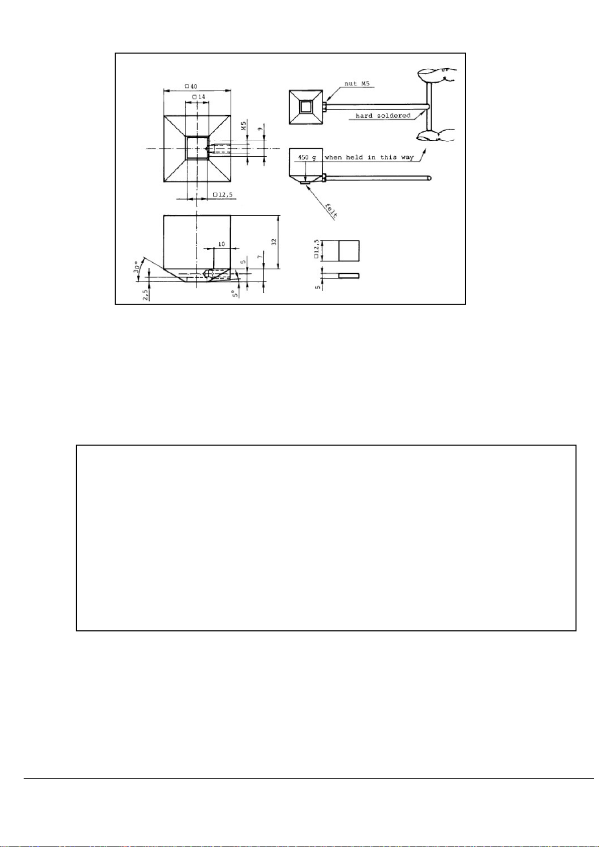
2.12.2.2 Resistance to Ethanol
Test method
The coating is rubbed in groups of 10 or 25 rubbing cycles (one cycl e = one complete to and from
movement) with the hand tool with an average speed of 2 m/min. In the case that more than 25 cycles are
required, the felt has to be soaked after each 25th cycle with Ethanol by means of a diffuser and the test
should be continued immediately. After the last test cycle rests of the Ethanol has to be wiped off
immediately from the tested surface with a soft cloth. (See figure)
Requirement: Rcs3 = 2x25 cycles
2-8
2.12.2.3 Resistance to Dry Abrasion
Test method
A fixed load of 2.5 N is used for this method. The specific pressure depends on the size of the area to be
tested. This implies, in relation to real use in practice, a higher load on ribs, raised lettering, etc. The
abrasive wheel is made from 3 discs of abrasive material (Scotch Brite Cleaning and finishing material type
A-VFN, thickness 6.35mm).
Requirement: Rda2 = 175Rev
2.12.2.4 Scratch Resistance (Scr)
Test method:
Test Roller used: Steel
Tester Position: Tester should be placed vertically with both rubber wheels on the test substrate
Average Speed: Very slow (2 m/min)
Test Pattern: 2 perpendicular to each other
Number of Stroke: 10cm (centre 6cm for assessment)
Mutual Distance between strokes: approx 1cm
Load Applied: 10N

2-9
To get a better insight in the real worn effect, test have to be performed starting with a load one step lower
•
and ending with a load one step higher then defined load.
2.13 Transportation & Handling
2.13.1 POS & Label Adhesion and Print Requirements
2.13.1.1 Label Adhesion
For Removable Labels
removed. It must not leave residue or permanently stains the surface.
For Permanent Labels (especially Product Family Labels): Should never lift-off at the edges or form large
bubbles underneath.
Tests: +70˚C Dry Heat Exposure Test (4 days)
Damp Heat Storage Test (7 days)
Criteria: After the tests, the label should conform to the requirements stated above.
2.13.1.2 Label Printing
For Permanent Labels
Test: Resistant to Ethanol- Requirement 1x25 cycles
Criteria: The printing should not deface or smudge. A slight overall lightening of the color is allowed but
there should not be any portion of print removed. Wordings should remain well legible.
(e.g. Point-of-Sale labels): Adhere neatly and flat on the surface and be easily
: Resistance to water and general household cleaning agents.
2.14 Transportation & Handling
2.14.1 Packaging Release Test Specifications
2.14.1.1 For All Regions EXCEPT China&India

2-10
2.14.1.2 For China & India Regions ONLY

2-11
2.14.2 Packaging Robustness Test Specifications
Note: To conduct this during Design Verification Test (DVT) phase only.
Purpose is to reveal weak points in the Product or Packaging and to take preventive actions to strengthen
these points so as to ensure a more robust Product/Packaging.
The test is referenced to ISTA-2A standard as follows:
Drop Sequence:
(a) Drop on 1x Corner, 3x Edges, 6x Faces
(b) Select the vulnerable corners (e.g. thin packaging or weak product corner)
(c) The 3x edges are those radiating from the chosen Corner, and to drop from shortest to longest edge
(d) The Faces drops should be done from the smallest to the largest face
2.14.3 Stacking Test
Condition: Reference IEC60068-2-3 Ca, Damp Heat Steady State at 40°C, 93%RH (±2%)
Duration: 1 day
Product is packed in packaging as per production
2-12
No of layer in stack: As indicated on Packaging Box graphics
Note: If simulated weight is used, a very rigid flat Plate shall be placed over a single layer of packages, and
the weights shall be evenly distributed over the plate.
Test Criteria: After the test, the packaging and its content should still be in good physical condition. The
polyfoam should not be severely cracked and the Cushioning-Ribs should not be over-compressed (badlycrushed).
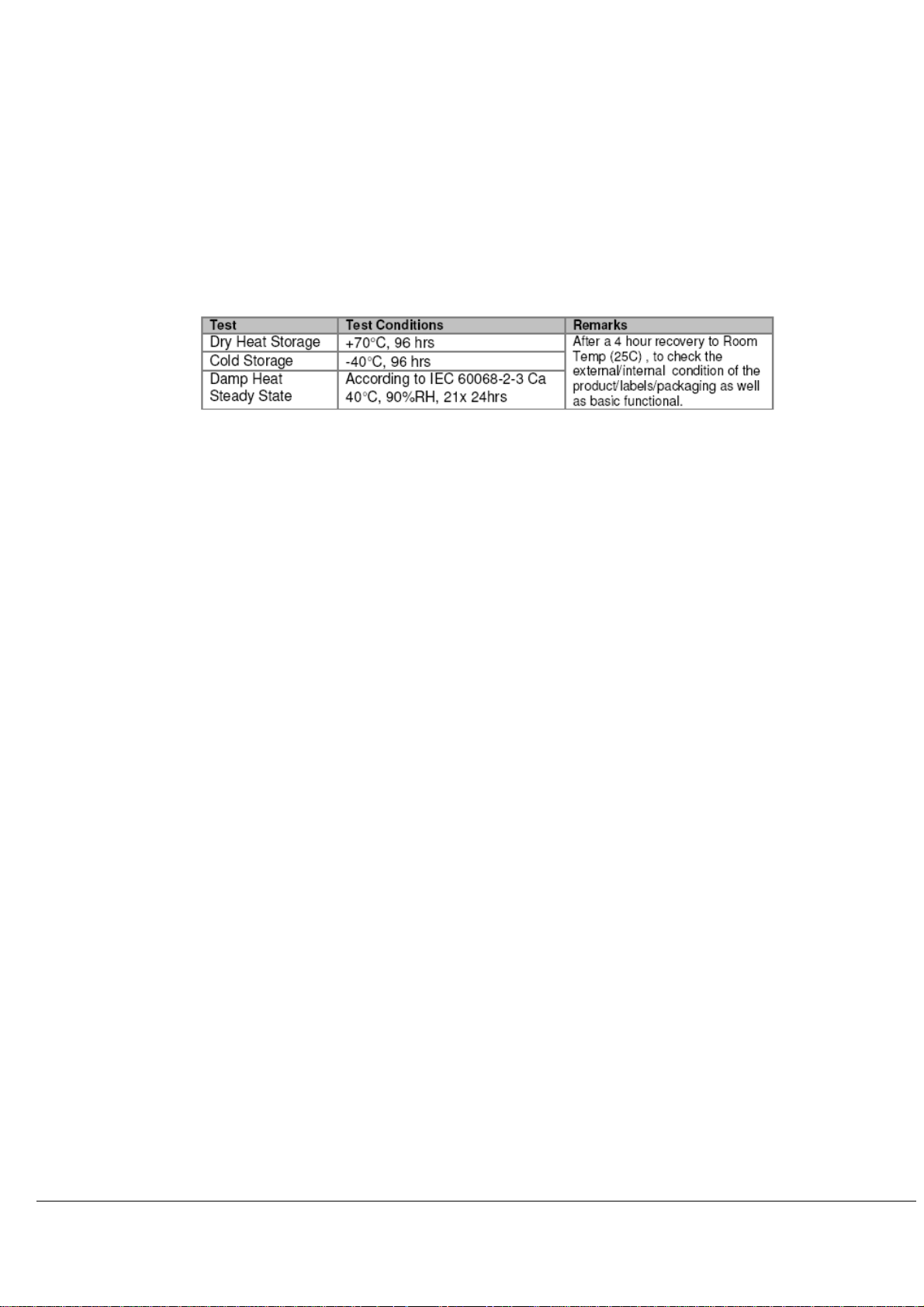
2.14.4 Storage Test (Packed)
Tests are conducted with the sets sealed in their packaging.

2-13
3 Regulatory
3.1 Safety
Player shall as a minimum comply with the requirements laid down in IEC 60065:2001/A1:2005. This is
applicable to all countries. However, in countries having national safety standards, which differ from IEC60065,
the relevant national standards are applicable,
For European countries: EN60065(latest addend um)
For USA, Canada: UL60065
All Information technology equipmentshall as a minimum comply with the requirements laid down in IEC609501:2001. This is applicable to all countries. However, in countries having national safety standardswhich differ
from IEC60950 the relevant national standards are applicable,
For European countries: EN60950-1:2001
For USA: UL1950
3.1.1 Laser Safety
All products shall as a minimum comply with the requirements laid down in IEC 60825-1:1993/A1:1997/A2:2001.
This is applicable to all countries. However, in countries having national safety standards, whi ch differ fro m IEC
60825-1, the relevant national standards are applicable,
For EU: EN60825-1:1994/A1:2002/A2:2001
For USA: CDRH (Centre for Devices and Radiological Health) 21 CFR1040.10, etc.
3.1.2 Touch Current
Standard Reference: IEC 60065:2001/A1:2005
Measured in accordance IEC 60990:1999
Requirement Test Condition
Tropical Climate: 0.35mA (peak)
Non-Tropical Climate: 0.7mA (peak)
• Ambient Temperature: Normal (25°C)
• Mains Supply: Nominal Voltage & Nominal Voltage +10%
• State: Power On (Any mode)
3.2 Electromagnetic Compatibility
Player shall as a minimum comply with the requirements laid down in CISPR13 for emissionandCISPR20 for
immunity. This is applicable to all countries. However in countries havingnational EMC requirements which differ
from CISPR 13 the relevant standards are applicable,
Emission:EN55013:2001/A1:2003/A2:2006 for European countries
Immunity: EN55020:2007 for European countries
Radiated, radio-frequency, electromagnetic field immunity: EN 61000-4-3:2006/A1:2007
Mains Harmonics:EN61000-3-2:2006
Voltage Fluctuations and Flicker: EN61000-3-3:1995/A1:2001/A2:2005
EMF: EN 62311:2008
FCC15 part 15B for USA, Canada
In countries where EMC standards are not compulsorily enforced, CISPR13
All information technology equipment shall as a minimum comply with the requirements laid do wn inCISPR22
emission and CISPR24 for immunity. This is applicable to all countries. However in countries having national
EMC requirementswhich differ from CISPR 22, the relevant standards are applicable,
Emission: EN55022:1998/A1:2000/A2:2003for European countries
Immunity: EN55024:1998/A1:2001/A2:2003for European countries
Mains Harmonics: EN61000-3-2:2006forEuropeancountries
FCC part 15 for USA
ETSI EN 301 489-1 v1.8.1 (2008-04)for European countries
must be enforced.
for
 Loading...