

Page 1
Manual
file:///D|/My%20Documents/dfu/BDL4221V/english/420wn6/MANUAL.HTM2005-11-07 12:54:38 PM
Page 2

Safety & Troubleshooting
Safety and Troubleshooting Information
Safety Precautions and Maintenance • FAQs • Troubleshooting • Regulatory Information •
Other Related Information
Safety precautions and maintenance
WARNING: Use of controls, adjustments or procedures other than those
specified in this documentation may result in exposure to shock, electrical
hazards and/or mechanical hazards.
Read and follow these instructions when connecting and using your computer monitor:
● Unplug the monitor if you are not going to use it for an extensive period of time.
● Unplug the monitor if you need to clean it with a slightly damp cloth. The screen many be
wiped with a dry cloth when the power is off. However, never use alcohol, solvents or
ammonia-based liquids.
● Consult a service technician if the monitor does not operate normally when you have
followed the instructions in this manual.
● The casing cover should be opened only by qualified service personnel.
● Keep the monitor out of direct sunlight and away from stoves or any other heat source.
● Remove any object that could fall into the vents or prevent proper cooling of the monitor’s
electronics.
● Do not block the ventilation holes on the cabinet.
● Keep the monitor dry. To avoid electric shock, do not expose it to rain or excessive moisture.
● If turning off the monitor by detaching power cable or DC power cord, wait for 6 seconds
before attach the power cable or DC power cord for normal operation.
● To avoid the risk of shock or permanent damage to the set do not expose the monitor to rain
or excessive moisture.
● When positioning the monitor, make sure the power plug and outlet are easily accessible.
● IMPORTANT: Always activate a screen saver program during your application. If a still
image in high contrast remains on the screen for an extended period of time, it may leave an
'after-image' or 'ghost image' on the front of the screen. This is a well-known phenomenon
that is caused by the shortcomings inherent in the LCD technology. In most cases the afterimage will disappear gradually over a period of time after the power has been switched off.
Be aware that the after-image symptom cannot be repaired and is not covered under
warranty.
file:///D|/My%20Documents/dfu/BDL4221V/english/420wn6/SAFETY/SAFETY.HTM (1 of 2)2005-11-07 12:54:40 PM
Page 3

Safety & Troubleshooting
Consult a service technician if the monitor does not operate normally when the operating
instructions given in this manual have been followed.
RETURN TO TOP OF THE PAGE
Installation Locations
● Avoid exposure to heat and extreme cold
● Do not store or use the product in locations exposed to heat, direct sunlight or extreme cold.
● Avoid moving the product between locations with large temperature differences. Choose a
site that falls within the following temperature and humidity ranges.
❍ Temperature: 0-35°C 32-95°F
❍ Humidity: 20-80% RH
● Do not subject the product to severe vibration or high impact conditions. Do not place the
product inside a car boot.
● Take care not to mishandle this product by either knocking or dropping during operation or
transportation.
● Do not store or use the product in locations where there is a high level of humidity or in dusty
environments. Do not allow water or other liquids to spill on or into the product.
RETURN TO TOP OF THE PAGE
file:///D|/My%20Documents/dfu/BDL4221V/english/420wn6/SAFETY/SAFETY.HTM (2 of 2)2005-11-07 12:54:40 PM
Page 4

About This Manual
About This Manual
About This Guide • Notational Descriptions
About This Guide
This electronic user's guide is intended for anyone who uses the Philips LCD Monitor TV. It
describes the features, setup, operation and other important information.
It includes the following sections:
● Safety and Troubleshooting Information provides tips and solutions for common problems as
well as other related information you may need.
● About This Electronic User's Manual gives an overview of information included, along with
notation icon descriptions and other documentation for your reference.
● Product Information gives an overview of the monitor's features as well as the technical
specifications for this monitor.
● Installing Your Monitor describes the initial setup process and gives an overview of how to
use the monitor.
● On-Screen Display provides information on adjusting the settings on your monitor.
● Remote Control provides information on adjusting the settings for your TV function.
● Customer Care and Warranty contains a list of worldwide Philips Consumer Information
Centres along with help desk phone numbers and information on the warranty applicable to
your product.
● Download and Print Option transfers this entire manual to your hard drive for easy reference.
RETURN TO TOP OF THE PAGE
Notational Descriptions
The following subsections describe notational conventions used in this document.
file:///D|/My%20Documents/dfu/BDL4221V/english/420wn6/ABOUT/ABOUT.HTM (1 of 2)2005-11-07 12:54:41 PM
Page 5
About This Manual
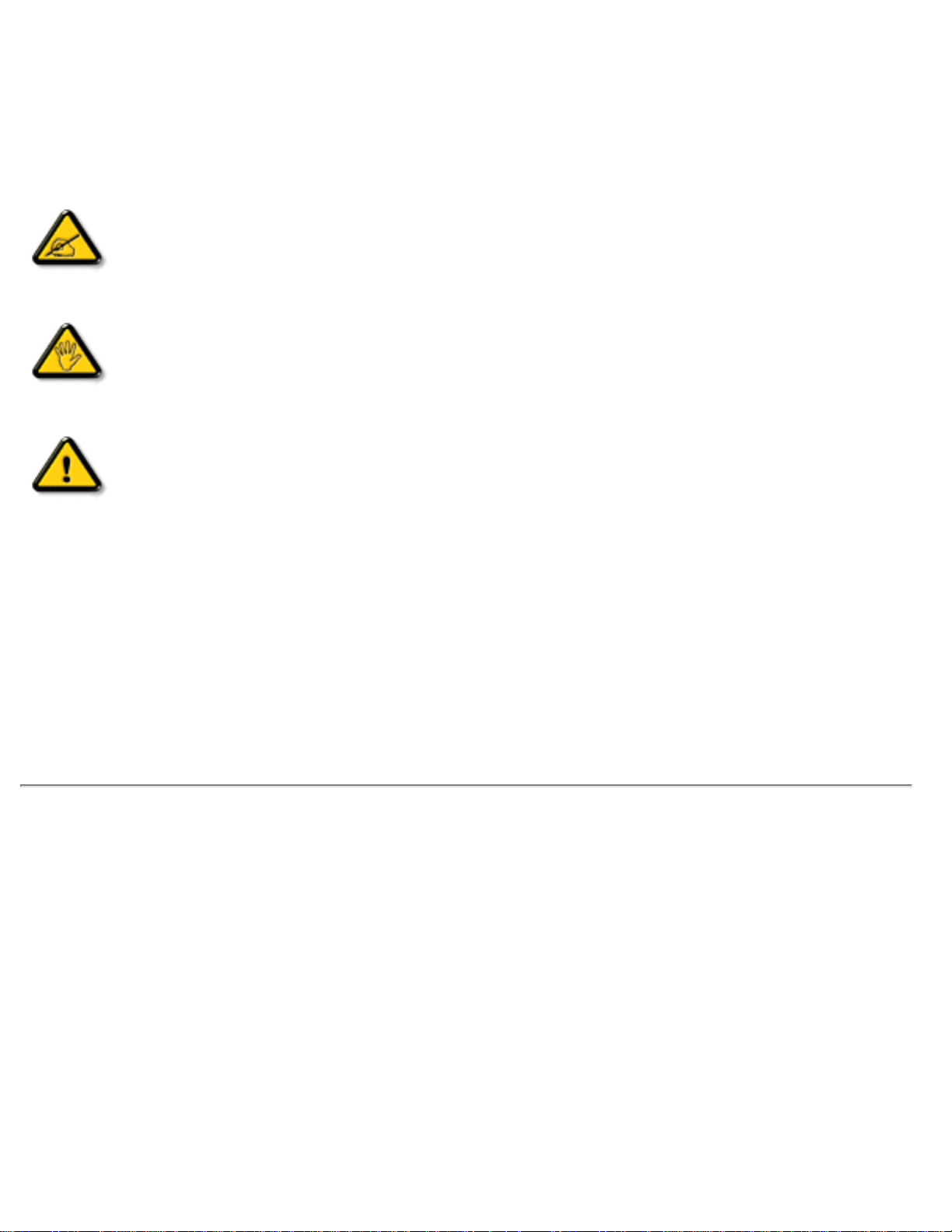
Notes, Cautions and Warnings
Throughout this guide blocks of text may be accompanied by an icon and printed in bold or italic
type. These blocks contain notes, cautions or warnings. They are used as follows:
NOTE: This icon indicates important information and tips that help you make
better use of your computer system.
CAUTION: This icon indicates information that tells you how to avoid either
potential damage to hardware or loss of data.
WARNING: This icon indicates the potential for bodily harm and tells you how
to avoid the problem.
Some warnings may appear in alternate formats and may not be accompanied by an icon. In such
cases, the specific presentation of the warning is mandated by the relevant regulatory authority.
RETURN TO TOP OF THE PAGE
©2005 Koninklijke Philips Electronics N.V.
All rights reserved. Reproduction, copying, use, modification, hiring, renting, public performance, transmission and/or
broadcasting in whole or in part is prohibited without written consent of Philips Electronics N.V.
file:///D|/My%20Documents/dfu/BDL4221V/english/420wn6/ABOUT/ABOUT.HTM (2 of 2)2005-11-07 12:54:41 PM
Page 6

Product Information
Product Information
Product Features • Lead-free Product • Technical Specifications • Resolution & Preset
Modes • Philips Pixel Defect Policy • Automatic Power Saving • Physical Specification •
Pin Assignment • Product Views • Serial Interface Comunication Protocol
Product Features
BDL4221V
● Less management effort for maximum productivity
❍ Multiple displays form a daisy chain to show uniform
❍ Monitor is network controllable for remote management
❍ Input connectors: CVBS, S-video, SCART, YPbPr.
● Better front of screen experience
❍ Motion adaptive deinterlacing for razor sharp images
❍ 3D comb filter separates color for a razor-sharp image
❍ WXGA, wide format 1366 x 768 resolution for sharper display
❍ Adaptive brightness intensifier technology
❍ Ready to display SDTV, EDTV, and HDTV formats
● Great convenience
❍ Zoom function to enable tiled matrix application
❍ Support hight-bandwidth digital content protection decryption
❍ Split screen for dual video/PC display
❍ Picture in picture for public display
*RF(TV input) is only available for 420WN6QS.
RETURN TO TOP OF THE PAGE
Lead-free Product
file:///D|/My%20Documents/dfu/BDL4221V/english/420wn6/PRODUCT/product.htm (1 of 10)2005-11-07 12:54:45 PM
Page 7

Product Information
Philips eliminated toxic substances like lead from its displays. Lead-free display
helps protect your health and promotes environmentally sound recovery and
disposal of waste from electrical and electronic equipment.Philips complies with the
European Community stringent RoHS Directive mandating restrictions on
hazardous substances in electrical and electronic equipment. With Philips, you can
be confident that your display device does not harm the environment.
Technical Specifications*
LCD PANEL
• Type TFT LCD
• Screen size 42"
• Pixel Pitch 0.227 x 0.681 mm
• LCD Panel type
1366 x 768 pixels
R.G.B. vertical stripe
Hard coating surface, anti-glare polarizer
• Effective viewing area 930.25 x 523.01 mm
• Display Colors 8 bits interface (16.7M colors)
PC SCANNING
• Vertical refresh rate 56Hz-75Hz
• Horizontal frequency 30kHz-63kHz
PC VIDEO
• Video dot rate < 85 MHz
• Input impedance
- Video
75 ohm
- Sync
2.2K ohm
• Input signal levels 0.7 Vpp
• Sync input signal
Separate sync
• Sync polarities Positive and negative
file:///D|/My%20Documents/dfu/BDL4221V/english/420wn6/PRODUCT/product.htm (2 of 10)2005-11-07 12:54:45 PM
Page 8
Product Information
• Input Frequency
WXGA Hsync 48 kHz, Vsync 60 Hz (N.I.)
SVGA Hsync 38 kHz, Vsync 60 Hz (N.I.)
VGA/DVI-D Hsync 31 kHz, Vsync 60 Hz (N.I.)
• Video interface
D-sub, S-Video, TV-RF, SCART composite, components
video, and DVI-D
AUDIO
• Input level for PC/SVHS/SCART 500 mV nominal
• Loudspeaker 10W Stereo Audio (200Hz~10kHz, 8 ohm, 10% THD)
OPTICAL CHARACTERISTICS
• Contrast ratio 1100:1 (with DCR on)
• Brightness
500 cd/m
2
(typ.)
• Peak contrast angle 6 o'clock
• White Chromaticity
x: 0.283 y: 0.297 (at 9300°K)
x: 0.313 y: 0.329 (at 6500°K)
x: 0.328 y: 0.344 (at 5700°K)
• Viewing Angle (C/R >5)
Upper >89° (typ.)
Lower >89° (typ.)
Left >89° (typ.)
Right >89° (typ.)
• Response time (G to G) 8 ms(typ.) 12 ms(max.)
sRGB
sRGB is a standard for ensuring correct exchange of colors between different devices (e.g.
digital cameras, monitors, printers, scanners, etc.)
Using a standard unified color space, sRGB will help represent pictures taken by an sRGB
compatible device correctly on your sRGB enabled Philips monitors. In that way, the colors are
calibrated and you can rely on the correctness of the colors shown on your screen.
Important with the use of sRGB is that the brightness and contrast of your monitor is fixed to a
predefined setting as well as the color gamut. Therefore it is important to select the sRGB
setting in the monitor's OSD.
To do so, at PC mode, open the OSD by pressing the MENU button of your monitor. Use the
down button to go to COLOR SETTINGS and press MENU again. Then move the down button
to go to NORMAL COLOR and press MENU again.
file:///D|/My%20Documents/dfu/BDL4221V/english/420wn6/PRODUCT/product.htm (3 of 10)2005-11-07 12:54:45 PM
Page 9

Product Information
* This data is subject to change without notice.
RETURN TO TOP OF THE PAGE
Resolution & Preset Modes
• Recommended 1360 x 768 at 60Hz
10 factory preset modes:
Resolution Mode H. freq (kHz) V. freq (Hz)
PC
640x350 VGA-1 31.469 70.086
640x480 VGA VESA 60 31.469 59.940
640x480 VGA VESA 75 37.500 75.000
720x400 IBM VGA 3H 31.468 70.087
800x600 SVGA VESA 56 35.156 56.250
800x600 SVGA VESA 60 37.879 60.317
800x600 SVGA VESA 75 46.875 75.000
1024x768 XGA VESA 60 48.363 60.004
1024x768 XGA VESA 75 60.023 75.029
1280x768 CVT 47.700 60.000
1280x720 CVT 44.772 59.855
1360x768 VESA 47.700 60.000
Video
720x480 480i 15.734 59.940
720x576 576i 15.625 50.000
file:///D|/My%20Documents/dfu/BDL4221V/english/420wn6/PRODUCT/product.htm (4 of 10)2005-11-07 12:54:45 PM
Page 10

Product Information
720x480 480p 31.470 60.000
720x576 576p 31.250 50.000
1280x720 720p 37.500 50.000
1280x720 720p 45.000 60.000
1920x1080 1080i 28.125 50.000
1920x1080 1080i 33.750 60.000
RETURN TO TOP OF THE PAGE
Automatic Power Saving
If you have VESA DPMS compliance display card or software installed in your PC, the monitor
can automatically reduce its power consumption when not in use. If an input from a keyboard,
mouse or other input device is detected, the monitor will then 'wake up' automatically. The
following table shows the power consumption and signaling of this automatic power saving
feature:
Power Management Definition
VESA Mode Video H-sync V-sync Power Used LED color
Active On Yes Yes 100 W (typ.) Blue
Sleep Off No No < 5 W Amber
Switch Off Off - - < 3 W Off
RETURN TO TOP OF THE PAGE
Physical Specifications
file:///D|/My%20Documents/dfu/BDL4221V/english/420wn6/PRODUCT/product.htm (5 of 10)2005-11-07 12:54:45 PM
Page 11
Product Information
• Dimension (WxHxD) *
incl. Pedestal, Speakers: 1272mm x 680mm x 300mm (49" x
26.7" x 11.8")
w/o Pedestal, Speakers: 1052mm x 644mm x 150mm (41.3"
x 25.3" x 5.9")
• Weight 35 kg (incl. Pedestal, Speakers)
• Power supply 100 — 240VAC, 60 — 50Hz
• Power consumption
PC Mode: 140 W (typ.)
TV Mode: 220 W (typ.)
• Temperature (operating) 5° C to 35° C
• Relative humidity 20% to 80%
• System MTBF
50K hrs (excluding CCFL 50Khrs)
* This data is subject to change without notice.
RETURN TO TOP OF THE PAGE
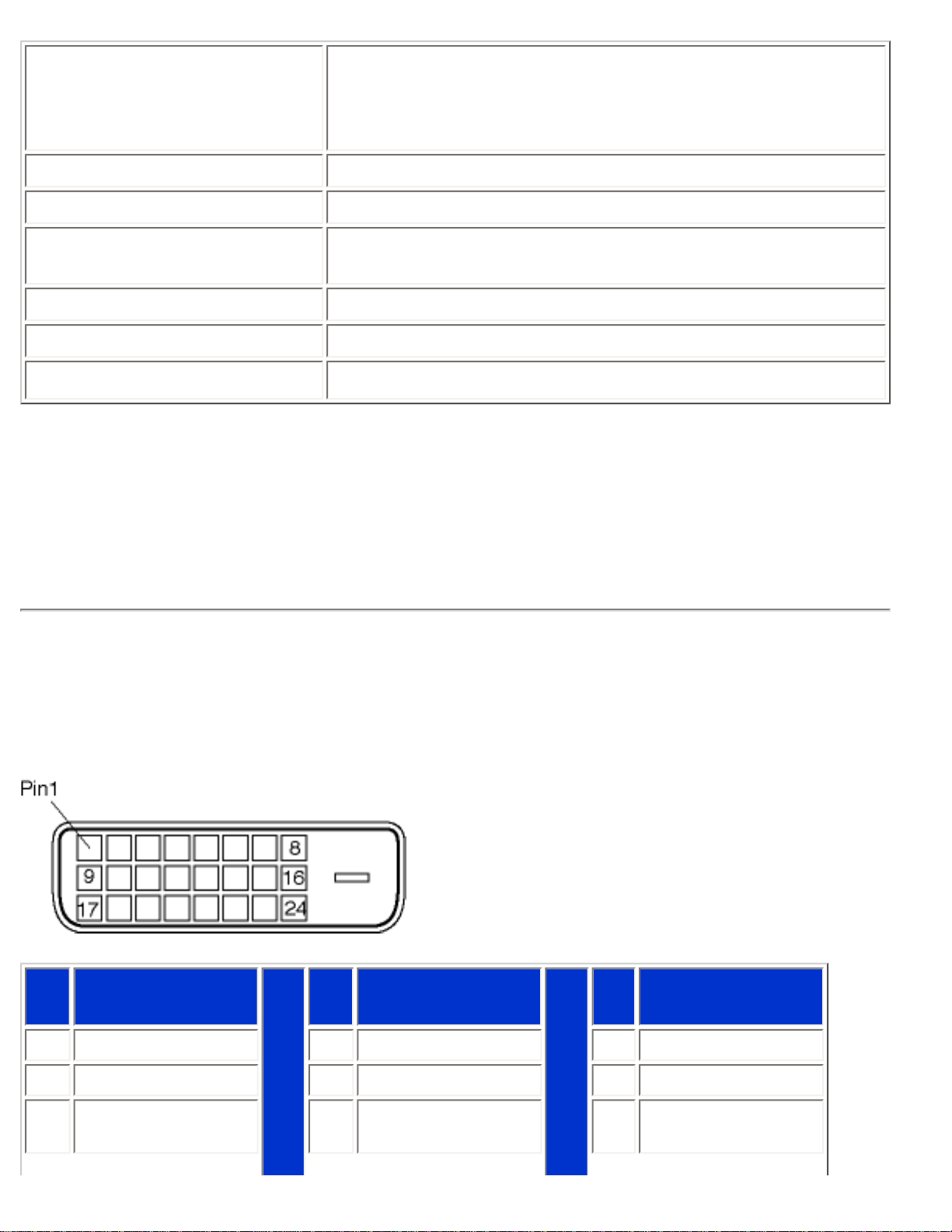
Pin Assignment
1. The digital only connector (DVI-D) contains 24 signal contacts organized in three rows of eight
contacts. Signal pin assignments are listed in the following table:
Pin
No.
Signal
Assignment
Pin
No.
Signal
Assignment
Pin
No.
Signal
Assignment
1
T.M.D.S. Data2-
9
T.M.D.S. Data1- 17 T.M.D.S. Data0-
2
T.M.D.S. Data2+
10
T.M.D.S. Data1+ 18 T.M.D.S. Data0+
3
T.M.D.S. Data2/4
Shield
11
T.M.D.S. Data1/3
Shield
19
T.M.D.S. Data0/5
Shield
file:///D|/My%20Documents/dfu/BDL4221V/english/420wn6/PRODUCT/product.htm (6 of 10)2005-11-07 12:54:45 PM
Page 12
Product Information
4
No connect
12
No connect 20 No connect
5
No connect
13
No connect 21 No connect
6
DDC Clock
14
+5V Power 22
T.M.D.S. Clock
Shield
7
DDC Data
15
Hot Plug Detect 23 T.M.D.S. Clock+
8
No connect 16 Ground (for +5V) 24 T.M.D.S. Clock-
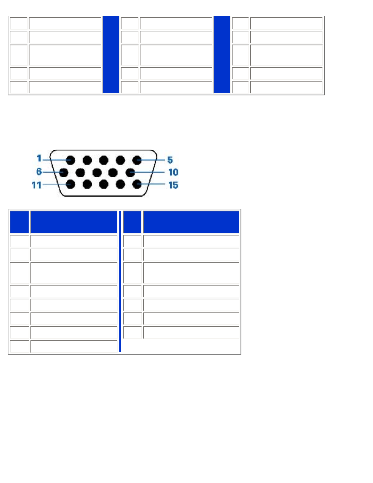
2. The 15-pin D-sub connector (male) of the signal cable:
Pin
No.
Assignment
Pin
No.
Assignment
1
Red video input
9
DDC +5V
2
Green video input
10
Cable detect
3
Blue video input
11
Identical output,
connected to pin 10
4
Ground
12
Serial data line (SDA)
5
NC
13
H. Sync / H+V
6
Red video ground
14
V. Sync
7
Green video ground
15
Data clock line (SCL)
8
Blue video ground
3. RS232 Connector
D-sub 9-pin male connector for communication with plasma engine or PC.
file:///D|/My%20Documents/dfu/BDL4221V/english/420wn6/PRODUCT/product.htm (7 of 10)2005-11-07 12:54:45 PM
Page 13
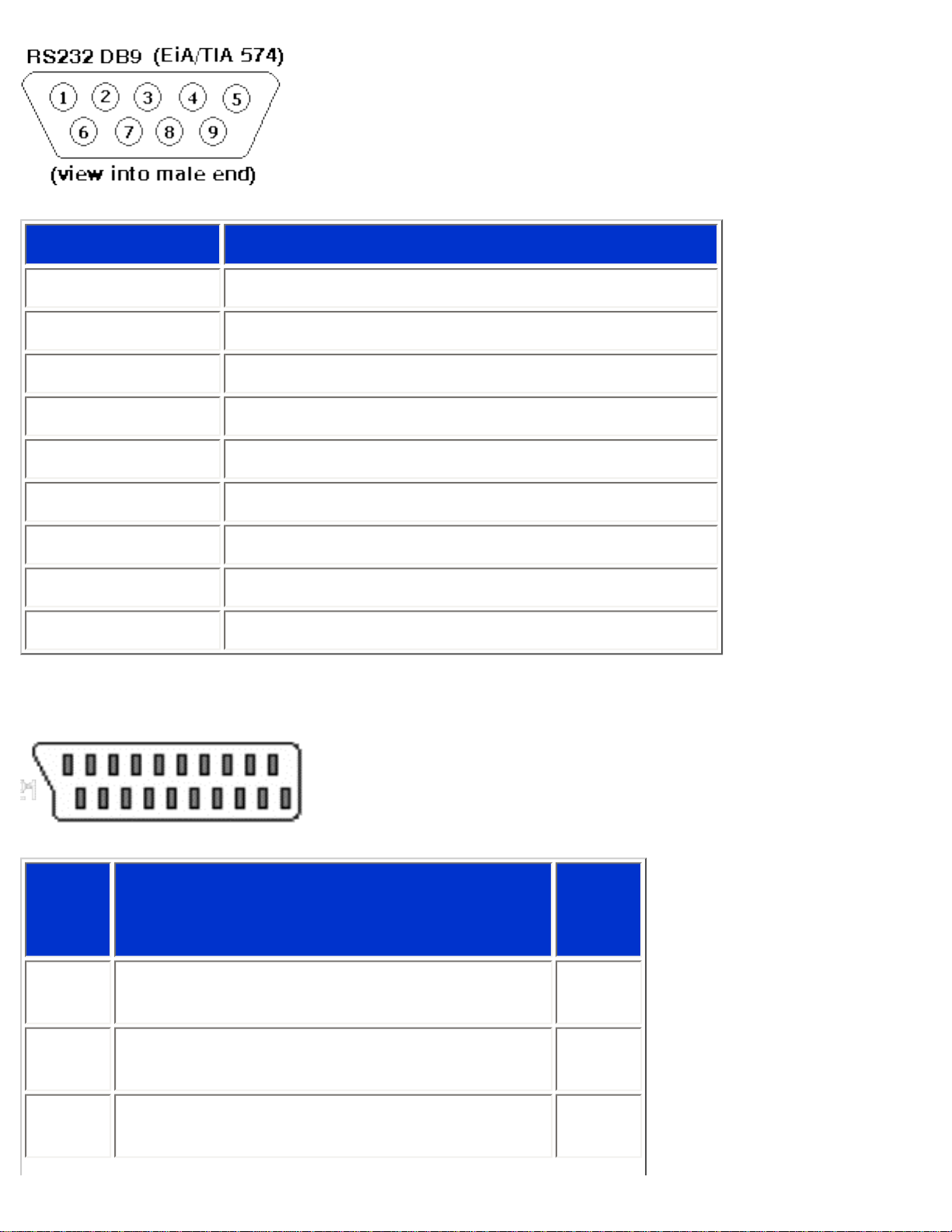
Product Information
Pin No.
RS-232 (EIA-232-A) Function
3 Transmit Data (TD) from DTE to DCE
2 Receive Data (RD) from DCE to DTE
7 Request to Send (RTS)
8 Clear to Send (CTS)
6 DCE Ready (DSR)
5 Signal Ground (SG)
1 Received Line Signal Detector (DCD)
4 DTE Ready (DTR)
9 Ring Indicator
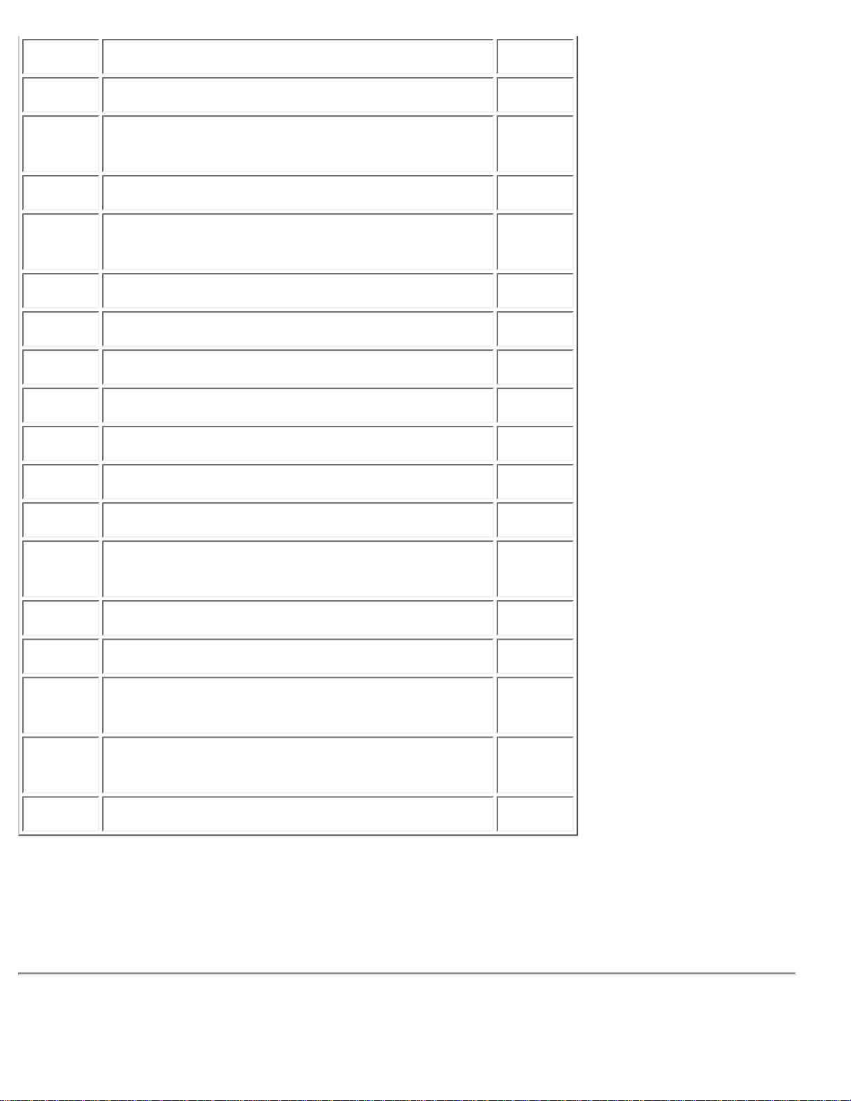
4. SCART Connector
Pin
No.
Signal Pin
No.
1
Audio right channel output (0.5 Vrms, < 1K
ohms)
2
2
Audio right channel input (0.5 Vrms, > 10K
ohms)
1
3
Audio left channel output (0.5 Vrms, < 1K
ohms)
6
file:///D|/My%20Documents/dfu/BDL4221V/english/420wn6/PRODUCT/product.htm (8 of 10)2005-11-07 12:54:45 PM
Page 14
Product Information
4 Audio ground 4
5 Blue signal ground 5
6
Audio left channel input (0.5 Vrms, > 10K
ohms)
3
7 Blue signal I/O (0.7 Vp-p, 75 ohms) 7
8
Function switching I/O (L: < 2V, H: > 10V, 10K
ohms)
8
9 Green signal ground 9
10 Intercommunication data line No. 1 10
11 Green signal I/O (0.7 Vp-p, 75 ohms) 11
12 Intercommunication data line No. 2 12
13 Red signal ground 13
14 Blanking signal ground 14
15 Red signal I/O (0.7 Vp-p, 75 ohms) 15
16
Blanking signal I/O (L: < 0.4V, H: >1.0V, 75
ohms)
16
17 Composite video signal ground 18
18 Blanking signal ground 17
19
Composite video signal output (1 Vp-p, 75
ohms, sync: negative)
20
20
Composite video signal input (1 Vp-p, 75
ohms, sync: negative)
19
21 Plug shield (common ground) 21
RETURN TO TOP OF THE PAGE
Product Views
file:///D|/My%20Documents/dfu/BDL4221V/english/420wn6/PRODUCT/product.htm (9 of 10)2005-11-07 12:54:45 PM
Page 15

Product Information
Follow the links to see various views of the monitor and its components.
Product Description
Serial Interface Comunication Protocol
Link
SICP Protocol.pdf
RETURN TO TOP OF THE PAGE
file:///D|/My%20Documents/dfu/BDL4221V/english/420wn6/PRODUCT/product.htm (10 of 10)2005-11-07 12:54:45 PM
Page 16
Installing your LCD Monitor/TV
Installing your LCD Monitor/TV
Product Description • Connecting to Your PC, TV antenna, DVD/VCR etc. • Getting Started • Optimizing
Performance
Product Description
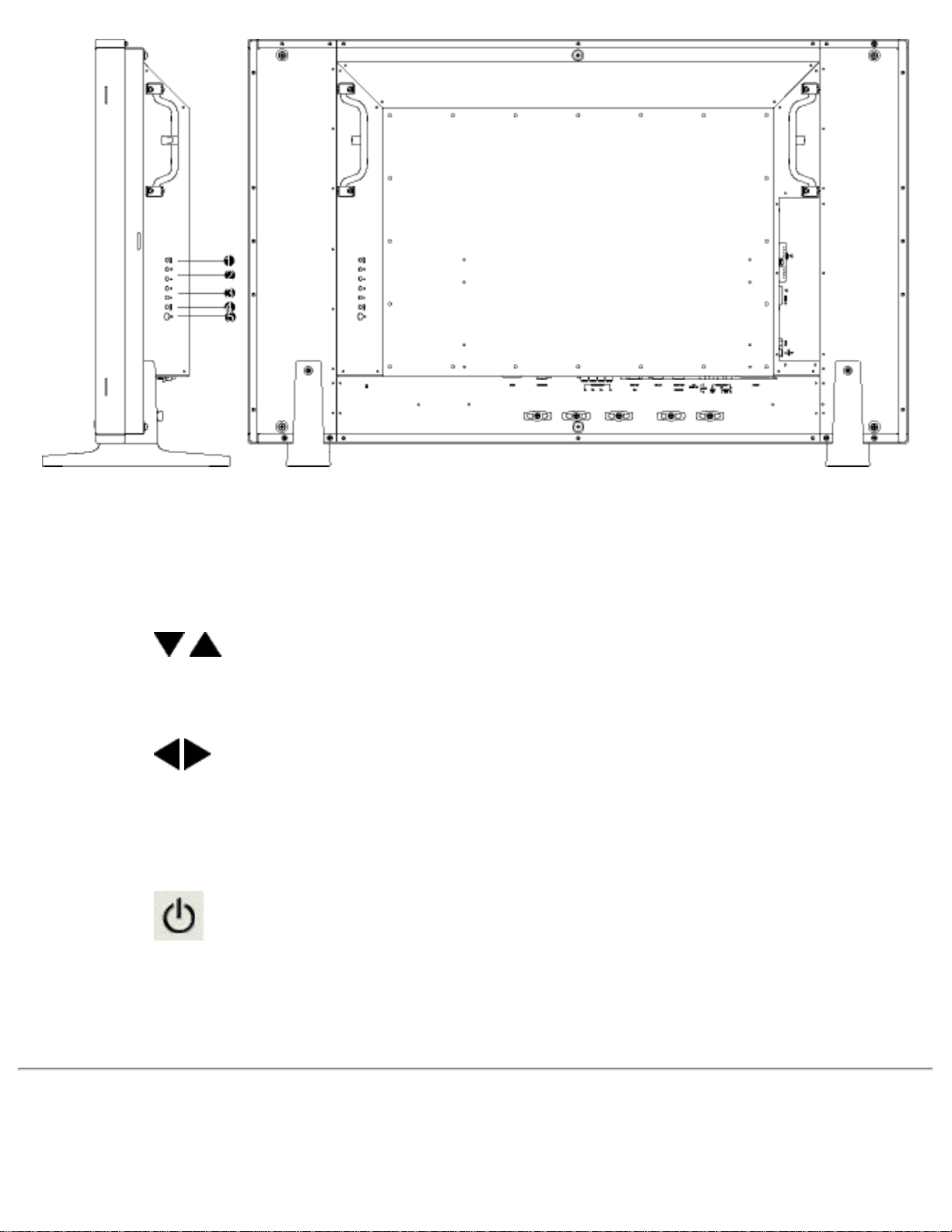
Installing your LCD Monitor/TV
Side View (Left)
file:///D|/My%20Documents/dfu/BDL4221V/english/420wn6/INSTALL/install.htm (1 of 6)2005-11-07 12:54:48 PM
Page 17
Installing your LCD Monitor/TV
1
INPUT
Selecting input source
2
Increase or decrease the channel number
or
moving up or down to highlight the function in OSD
3
Increase or decrease the level of audio volume
or
moving left or right to highlight the sub-menu in the selected function
of OSD
4
MENU
Open the OSD or confirm the selected function
5
DC power switch On/Off
RETURN TO TOP OF THE PAGE
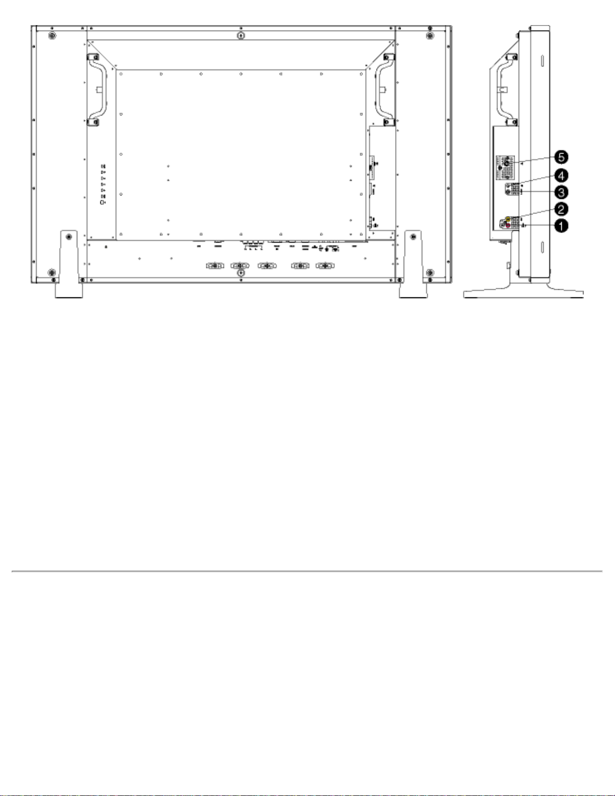
Side View (Right)
file:///D|/My%20Documents/dfu/BDL4221V/english/420wn6/INSTALL/install.htm (2 of 6)2005-11-07 12:54:48 PM
Page 18
Installing your LCD Monitor/TV
1 Audio input for composite input
Audio (left and right) in put for compo site
signal in put.
2 Composite input Composite (CVBS) signal input
3 S-Video input S-Video signal input
4 Earphone output Earphone output
5 TV tuner TV tuner input (available in TV version only)
RETURN TO TOP OF THE PAGE
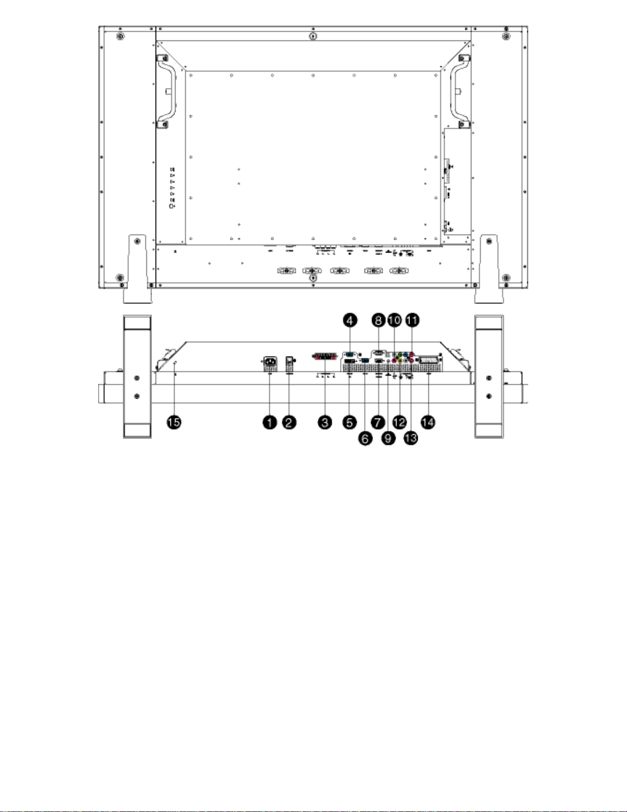
Rear View
file:///D|/My%20Documents/dfu/BDL4221V/english/420wn6/INSTALL/install.htm (3 of 6)2005-11-07 12:54:48 PM
Page 19
Installing your LCD Monitor/TV
1
AC in
AC power in
2 AC power AC power switch
3 Speakers output
External speakers output
4 D-Sub output
PC analog D-Sub output
5 DVI-D input
PC digital input
6 D-Sub input
PC analog D-Sub input
7 RS232 input
RS232 network connection Input
8 RS232 output
RS232 network connection output for the use of
loop through function
file:///D|/My%20Documents/dfu/BDL4221V/english/420wn6/INSTALL/install.htm (4 of 6)2005-11-07 12:54:48 PM
Page 20
Installing your LCD Monitor/TV
9 PC audio
PC stereo audio input
10 Audio input for component signal
Audio (left and right) input for component signal
input
11 Component input
Component (YP
bPr
) signal input
12 Composite output
Composite (CVBS) output for the use of loop
through function
13 Audio output for composite output
Audio (left and right) out put for compo site signal
out put.
14 External / EURO-AV
SCART connection (for the use of European
model only)
15 Kensington lock
Kensington lock
Optimising Performance
● For best performance, ensure that your display settings are set at 1360x768, 60Hz.
Note: You can check the current display settings by pressing the 'MENU' button
once.
● You can also install the Flat Panel Adjust (FP Adjust) program, a program for getting the best performance
out of your monitor. This is included on this CD. Step-by-step instructions are provided to guide you
through the installation process. Click on the link to find out more about this program.
More about FP_setup04.exe
RETURN TO TOP OF THE PAGE
file:///D|/My%20Documents/dfu/BDL4221V/english/420wn6/INSTALL/install.htm (5 of 6)2005-11-07 12:54:48 PM
Page 21
On Screen Display
On Screen Display
On Screen Display Control • Using Your Remote Control
On Screen Display Controls
An overall view of the On-Screen Display (OSD) structure is shown below. You can use it as a reference for further
adjusting your Monitor/TV.
There are two different modes of OSD available for different models:
● PC Mode
● TV Mode
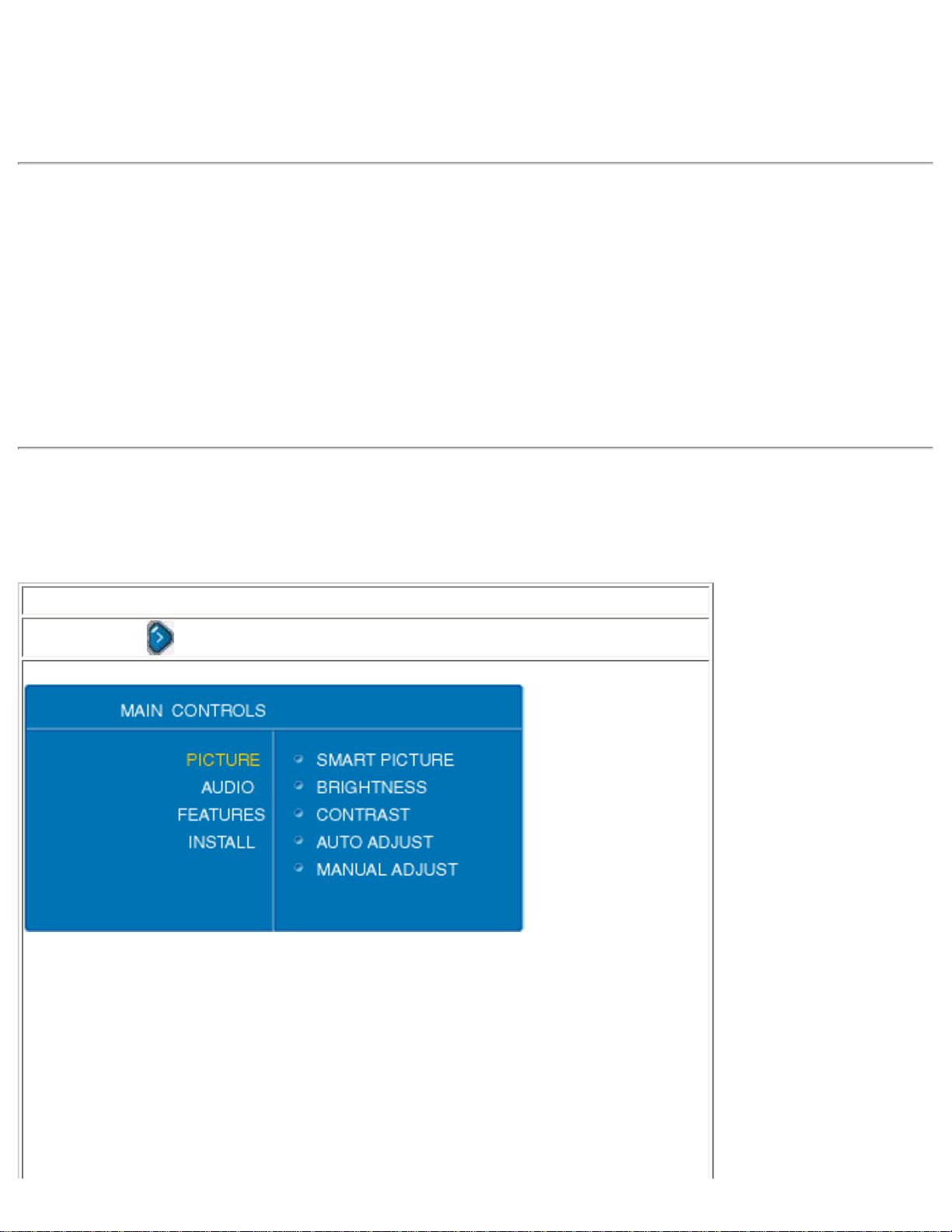
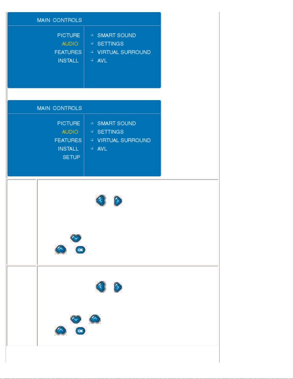
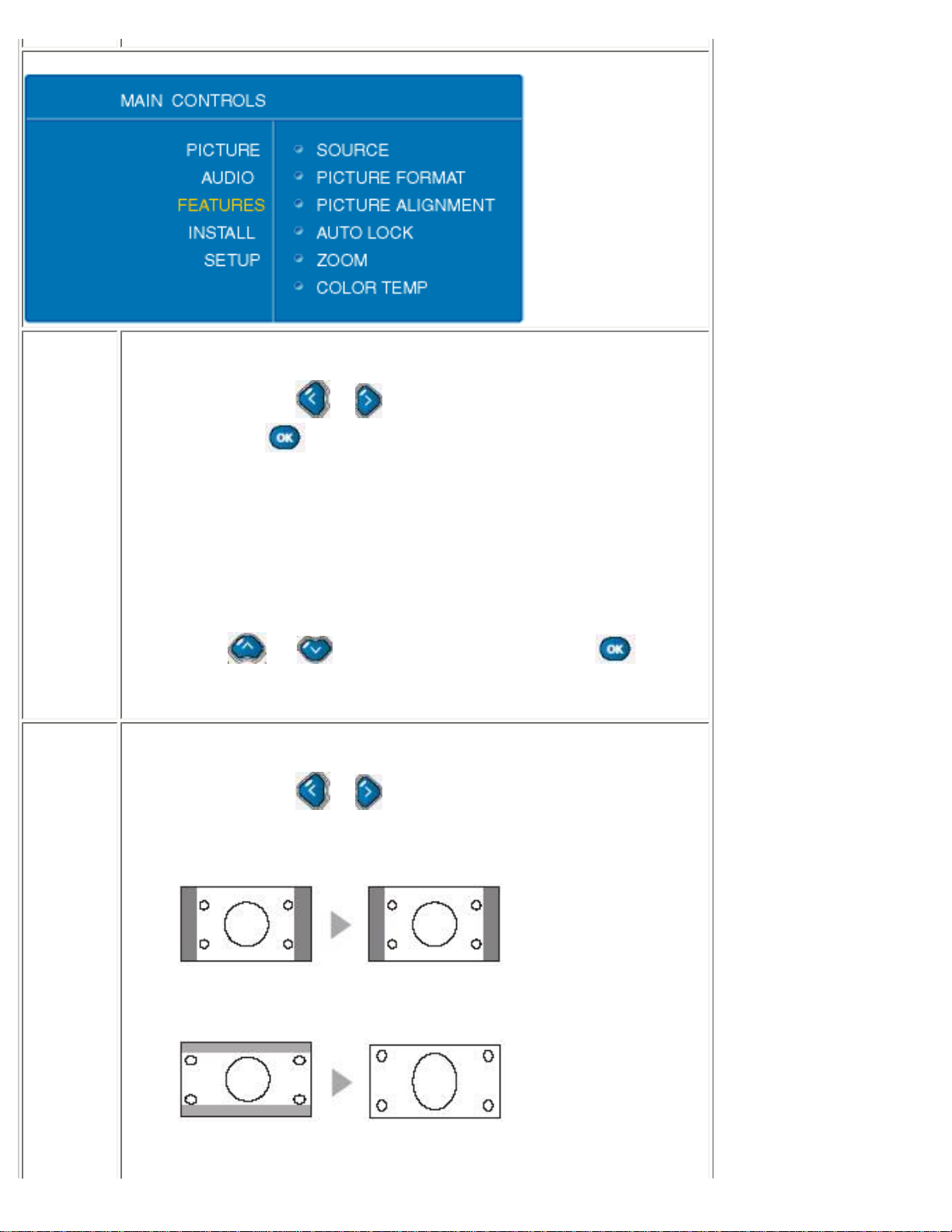
Main menu
There is a slight difference between PC mode and TV mode: Setup selection is available in TV mode only.
Sub-menus
Picture: press to enter sub-menu selections.
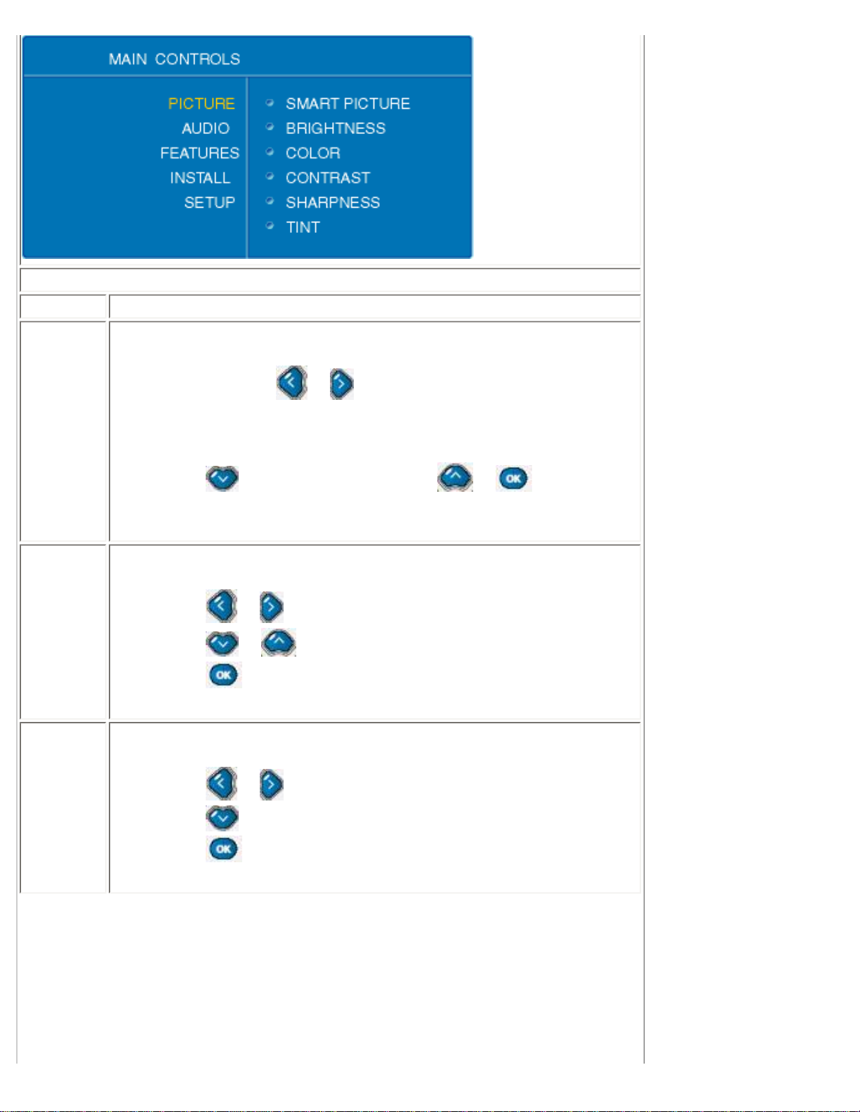
PC Mode
TV Mode
file:///D|/My%20Documents/dfu/BDL4221V/english/420wn6/OSD/osddesc.htm (1 of 22)2005-11-07 12:54:53 PM
Page 22
On Screen Display
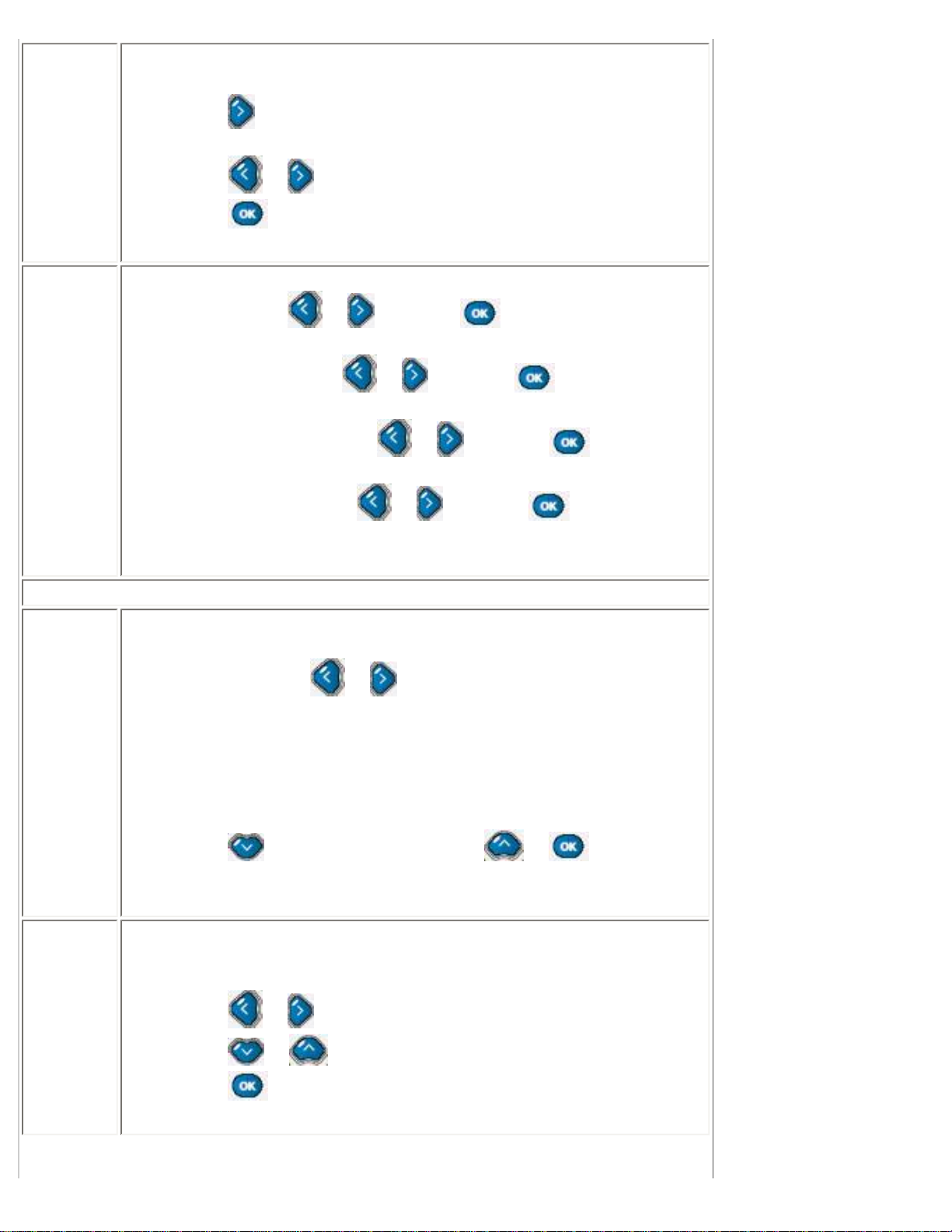
PC mode
Selection How to use
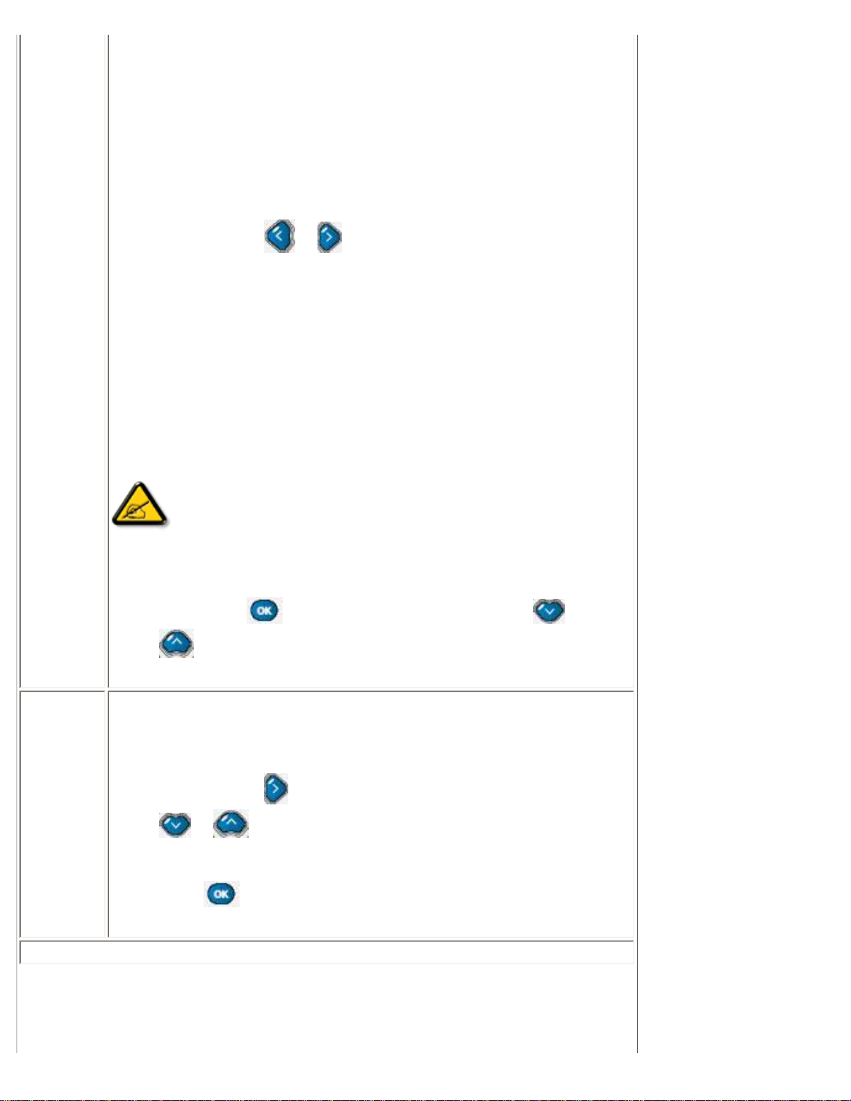
Smart
Picture
In PC mode
● Users can press or to toggle between
❍ Normal
❍ Warm
❍ Cool
● Press to next sub-menu selection or to return to
main menu.
Brightness
Adjust image brightness.
● Press or to adjust,
● Press or to adjacent sub menu selections,
● Press to return to main menu.
Contrast
Adjust image sharpness.
● Press or to adjust,
● Press to adjacent sub-menu selections,
● Press to return to main menu.
file:///D|/My%20Documents/dfu/BDL4221V/english/420wn6/OSD/osddesc.htm (2 of 22)2005-11-07 12:54:53 PM
Page 23
On Screen Display
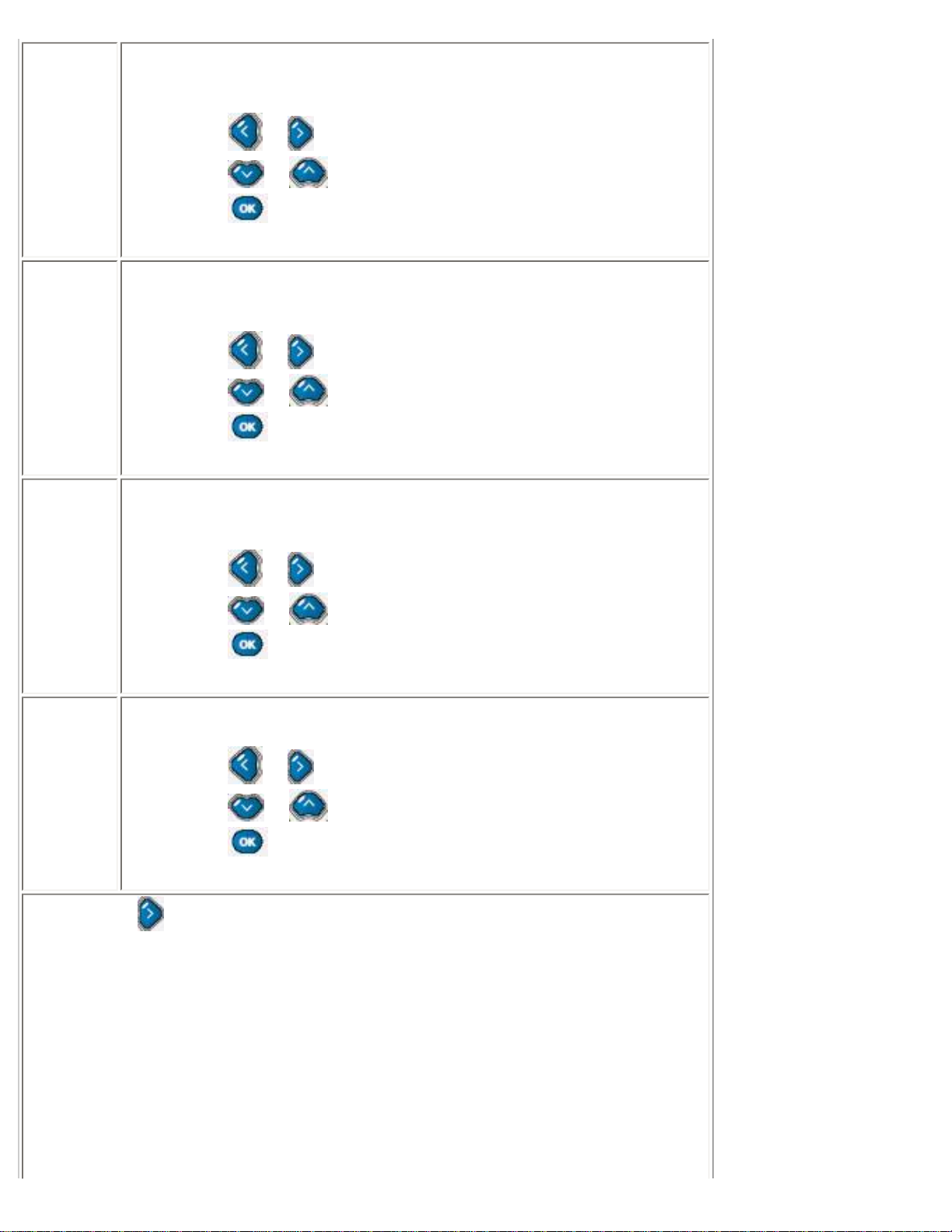
Auto
Adjust
Automatic fine tuning display geometry and time frequency parameter.
● Press to start,
● A selection of Store? Yes/No will appear.
● Press or to toggle between Yes and No.
● Press to confirm and return to sub-menu.
Manual
Adjust
Adjust display geometry and time frequency parameters.
● Phase: Press or to adjust, to confirm and return to
sub-menu.
● Clock: Phase: Press or to adjust, to confirm and
return to sub-menu.
● Horizontal: Phase: Press or to adjust, to confirm
and return to sub-menu.
● Vertical: Phase: Press or to adjust, to confirm and
return to sub-menu.
TV mode
Smart
Picture
In TV mode
● Users can press or to toggle between
❍ Personal
❍ Movies
❍ Sports
❍ Weak Signal
❍ Multimedia
❍ Night
● Press to next sub-menu selection, or to return to
main menu.
Brightness
Adjust image brightness. It is adjustable only when Smart Picture is in
personal mode.
● Press or to adjust,
● Press or to adjacent sub-menu selections,
● Press to return to main menu.
file:///D|/My%20Documents/dfu/BDL4221V/english/420wn6/OSD/osddesc.htm (3 of 22)2005-11-07 12:54:53 PM
Page 24
On Screen Display
Contrast
Adjust image sharpness. It is adjustable only when Smart Picture is in
personal mode.
● Press or to adjust,
● Press or to adjacent sub-menu selections,
● Press to return to main menu.
Color
Adjust image color saturation. It is adjustable only when Smart Picture is
in personal mode.
● Press or to adjust,
● Press or to adjacent sub-menu selections,
● Press to return to main menu.
Sharpness
Adjust image sharpness. It is adjustable only when Smart Picture is in
personal mode.
● Press or to adjust,
● Press or to adjacent sub-menu selections,
● Press to return to main menu.
Tint
Adjust image hue level.
● Press or to adjust,
● Press or to adjacent sub-menu selections,
● Press to return to main menu.
Audio: press
to enter sub-menu selections
PC Mode
file:///D|/My%20Documents/dfu/BDL4221V/english/420wn6/OSD/osddesc.htm (4 of 22)2005-11-07 12:54:53 PM
Page 25
On Screen Display
TV Mode
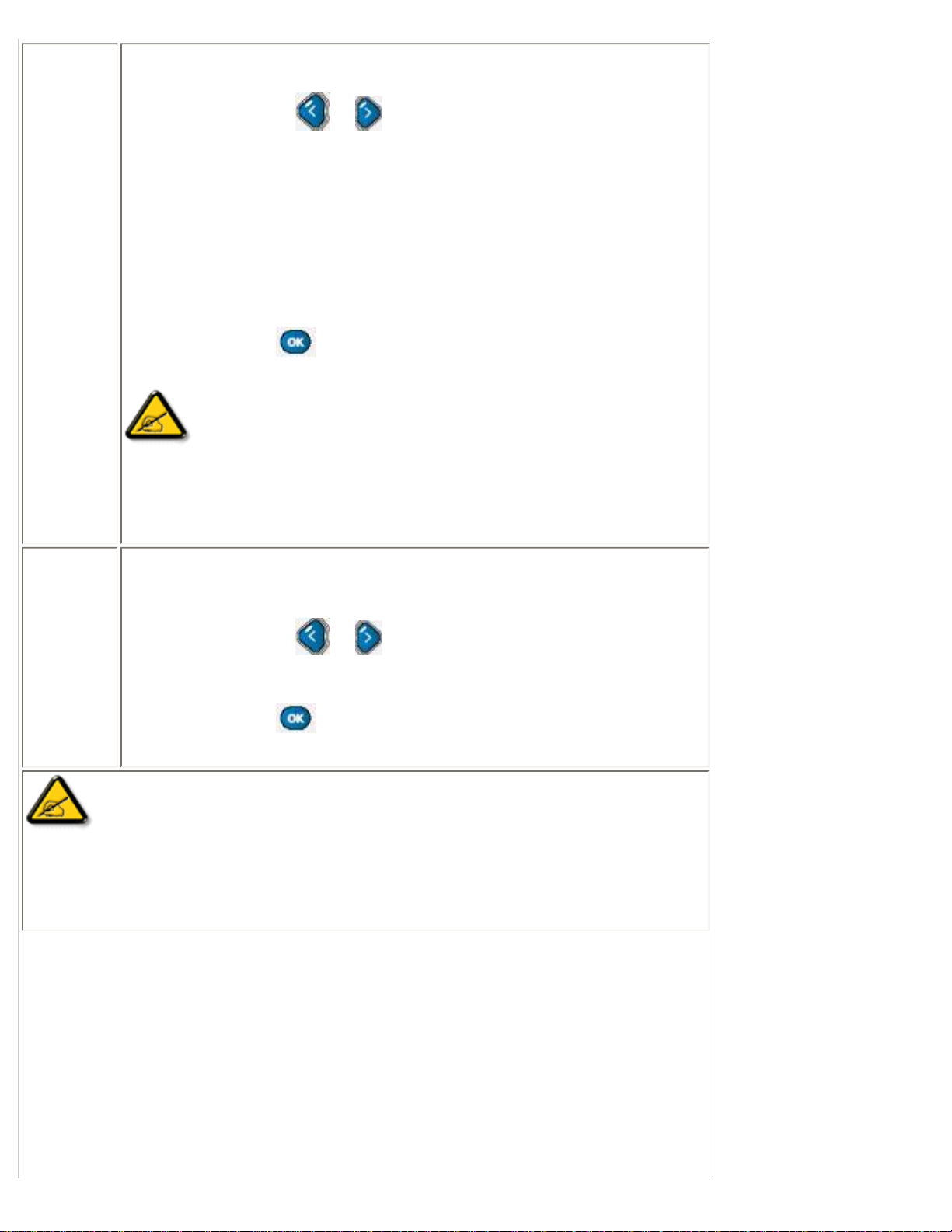
Smart
Sound
Preset audio modes.
● Users can press or to toggle between
❍ Personal
❍ News
❍ Music
❍ Theater
● Press to next sub-menu selections
● or to return to main menu.
Settings
Adjust audio setting parameters.
● Users can press or to toggle between
❍ Treble
❍ Bass
❍ Balance
● Press or to adjacent sub-menu selections
● or to return to main menu.
file:///D|/My%20Documents/dfu/BDL4221V/english/420wn6/OSD/osddesc.htm (5 of 22)2005-11-07 12:54:53 PM
Page 26
On Screen Display
Virtual
Surround
Sound
Switch virtual surround effect on or off.
● Users can press or to toggle between
❍ On
❍ Off
● Press or to adjacent sub-menu selections, to
return to main menu.
AVL
Auto Volume Limit, adjust volume level automatically to prevent sudden
peak load exceeds design limit.
● Users can press or to toggle between
❍ Yes
❍ No
● Press or to adjacent sub-menu selections, to
return to main menu.
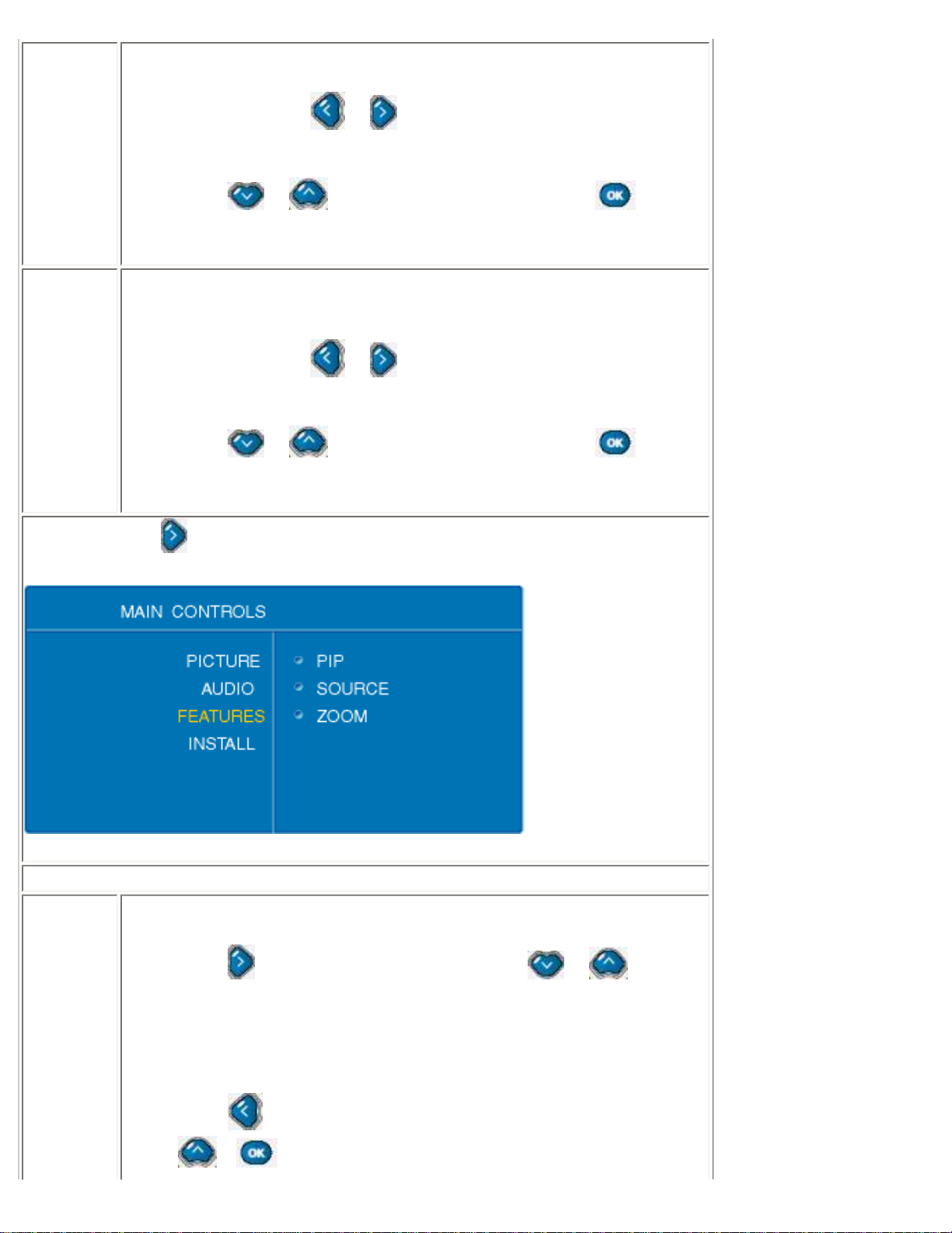
Features: press
to enter sub-menu selections.
PC mode
PIP
Picture in Picture size choices.
● Press to enter PIP sub-menu, and press or to
selection between
❍ Size
❍ Video
❍ Audio
❍ Display
● Press to return from PIP sub-menu to sub-menu, or press
or to return to main menu.
file:///D|/My%20Documents/dfu/BDL4221V/english/420wn6/OSD/osddesc.htm (6 of 22)2005-11-07 12:54:53 PM
Page 27
On Screen Display
PIP Sub-menu
Size
PIP window size adjustment.
● Users can use or to toggle between
❍ Small
❍ Medium
❍ Large
❍ PBP
❍ Off
● Press or to return to upper level sub-menu, to next
selection.
Video
Video source of the PIP window.
● Users can use or to toggle between
❍ TV
❍ AV (CVBS)
❍ S-video
❍ EXT (Scart)
● Press or to adjacent sub-menu selections, to
return to upper level sub-menu.
Audio
Audio source of the PIP window.
● Users can use or to toggle between
❍ PC
❍ PIP
● Press or to adjacent sub-menu selections, to
return to upper level sub-menu.
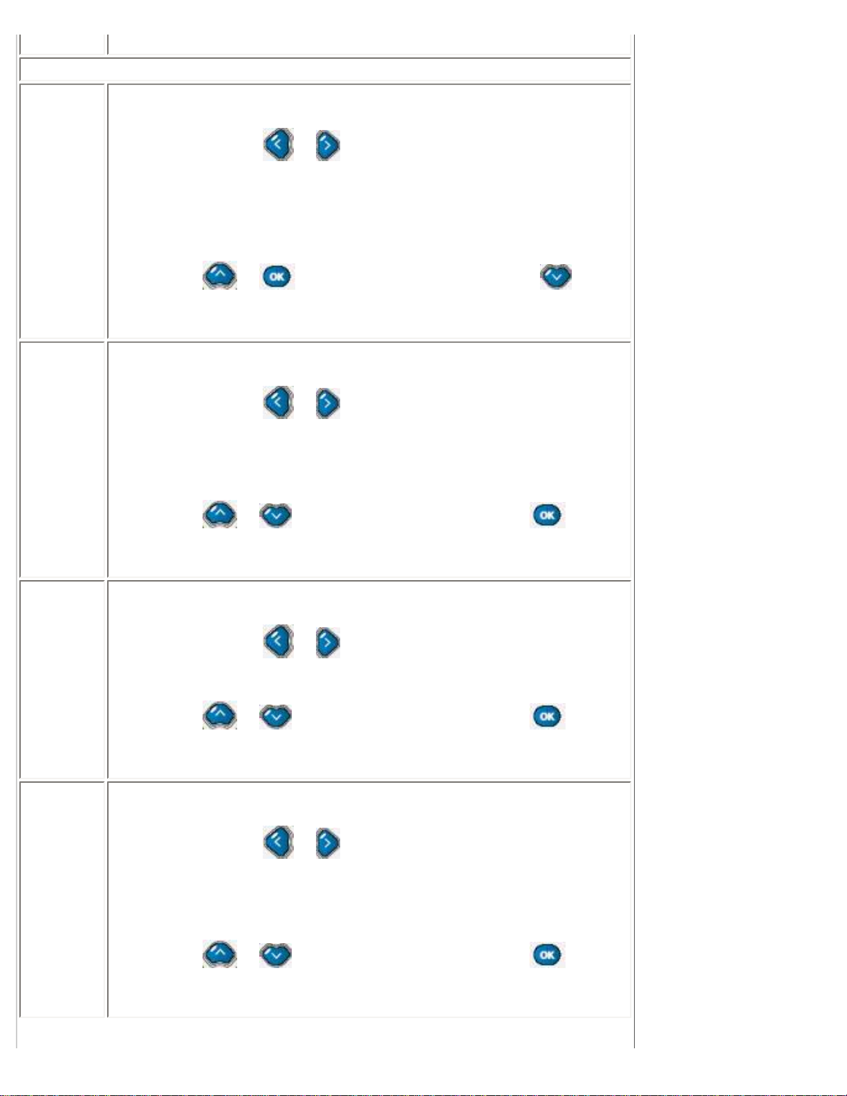
Display
PIP window location selection.
● Users can use or to toggle between
❍ Icon1 (upper right corner of the screen)
❍ Icon2 (lower right corner of the screen)
❍ Icon3 (lower left corner of the screen)
❍ Icon4 (upper left corner of the screen)
● Press or to adjacent sub-menu selections, to
return to upper level sub-menu.
file:///D|/My%20Documents/dfu/BDL4221V/english/420wn6/OSD/osddesc.htm (7 of 22)2005-11-07 12:54:53 PM
Page 28
On Screen Display
Source
Choices of video source for main screen.
● Users can use or to toggle between
❍ PC
❍ DVI
❍ HDCP
❍ TV
❍ AV (CVBS)
❍ S-video
❍ EXT (Euro connector, Scart)
❍ HD (YPbPr)
● Press or to adjacent sub-menu selections, to
return to upper level sub-menu.
Zoom
Choices for Zoom function.
● Users can use to enter next level sub-menu and Zoom sub-
menu.
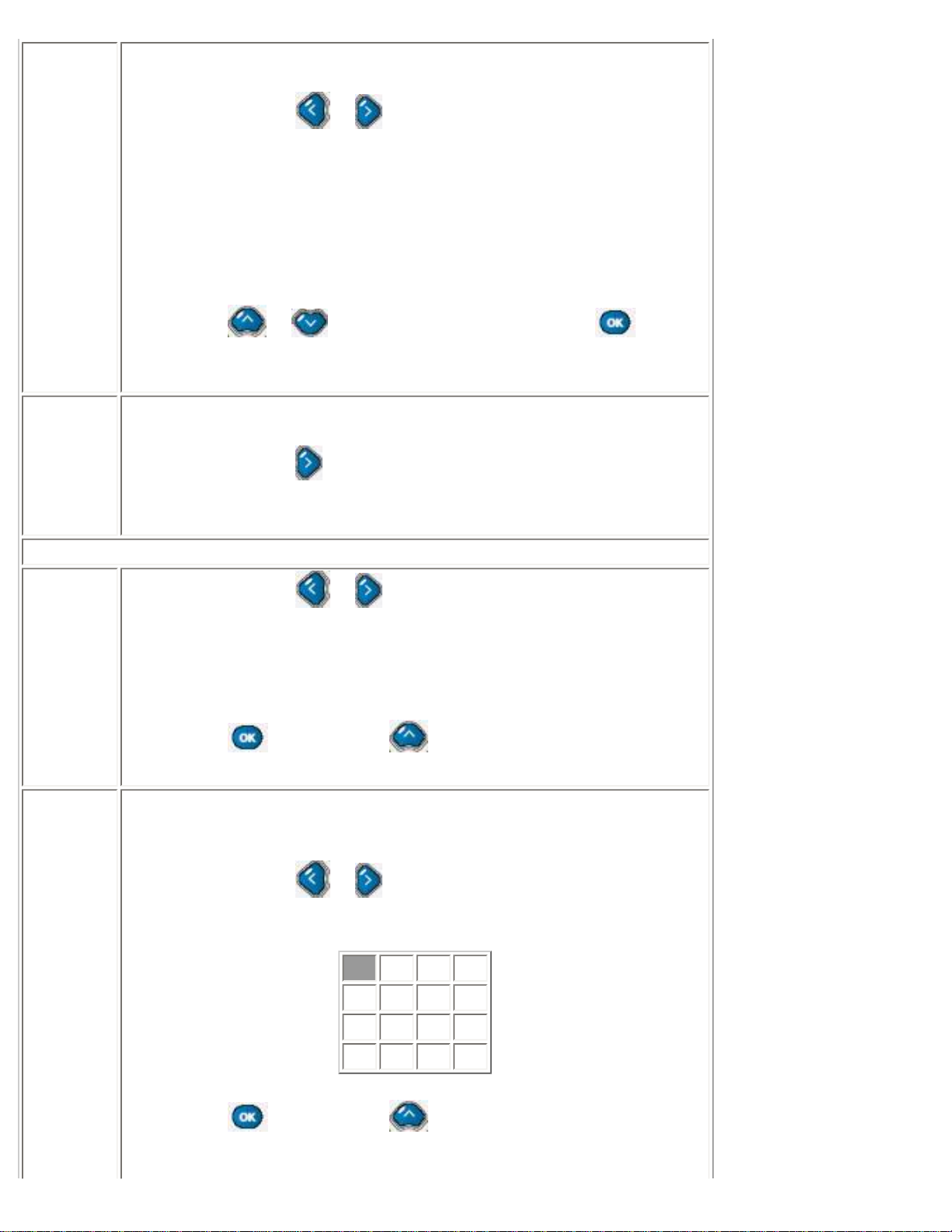
Zoom sub-menu
Zoom Type
● Users can use or to toggle between
❍ Off
❍ 4x4
❍ 3x3
❍ 2x2
❍ 1x5
● Press to confirm and to return to upper level sub-menu.
Zoom ID
This selections is only available when one of zoom types is chosen.
When zoom type is off, this selections is unavailable.
● Users can use or to toggle between IDs. For example,
when 4x4 is chosen, the ID selection are
A1 A2 A3 A3
B1 B2 B3 B4
C1 C2 C3 C4
D1 D2 D3 D4
● Press to confirm and to return to Zoom Type and exit to
upper level sub-menu.
file:///D|/My%20Documents/dfu/BDL4221V/english/420wn6/OSD/osddesc.htm (8 of 22)2005-11-07 12:54:53 PM
Page 29
On Screen Display
TV mode
Source
Choices of video source for main screen.
● Users can use or to toggle between each signal source,
then press
to confirm your select.
❍ PC
❍ DVI
❍ HDCP
❍ TV
❍ AV (CVBS)
❍ S-Video
❍ Ext (Euro connector, Scart)
❍ HD (YP
bPr
)
● Press or to adjacent sub-menu selections to
return to upper level sub-menu.
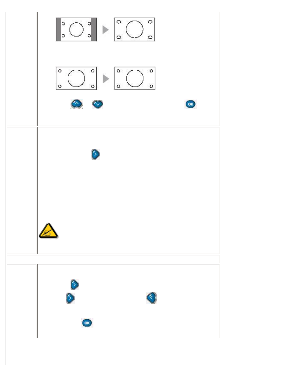
Picture
Format
Selections of image format.
● Users can use or to toggle between
❍ Automatic
❍ 4:3
❍ Zoom 16:9
❍ Wide screen
file:///D|/My%20Documents/dfu/BDL4221V/english/420wn6/OSD/osddesc.htm (9 of 22)2005-11-07 12:54:53 PM
Page 30
On Screen Display
❍ Super wide
● Press or to adjacent sub-menu selections to
return to upper level sub-menu.
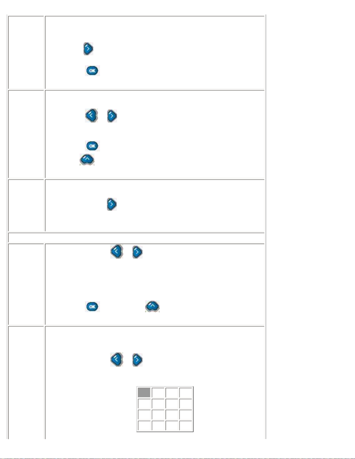
Auto Lock
Lock up specific channels to prevent underage viewers to watch improper
TV content.
● Users can use to enter next level sub-menu.
● When you select this function for the first time, a sub-menu will
appear and ask you to input access code.You can use number
buttons to input a four-digit access code.Then a confirming submenu will appear and ask you to input the same access code once
more to confirm.
● After the first time, each time you try to access this function, a sub-
menu will appear to request for a access code.If the code is
correct, you can start the setting process of this function.
Note: Please remember that 0711 is a default access code.If
you forget the access code you set or someone else has changed your
access code.You can always use 0711 to unlock.
Auto Lock sub-menu
Lock
Program
Lock selected channel from underage viewers.
● Press to enter.
● Use to block the current channel, to unlock this channel.
● Use number buttons to select the channel you wish to block of
unlock.
● Then, use to confirm and return to upper level sub-menu.
file:///D|/My%20Documents/dfu/BDL4221V/english/420wn6/OSD/osddesc.htm (10 of 22)2005-11-07 12:54:53 PM
Page 31
On Screen Display
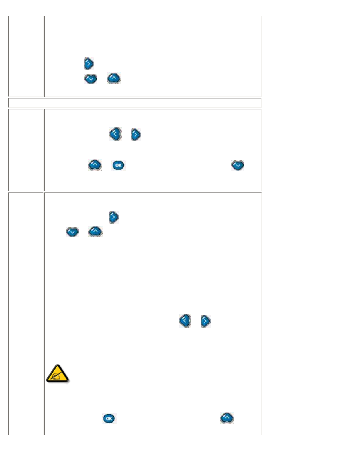
Change
code
Change program lock access code. Users need to set a four digits
access code to enable the Auto Lock function.
● Use to enter code input mode
● Use number buttons to a new four-digit code
● Press to confirm and return to upper level sub menu.
Clear all
Clear all of the locked channels.
● Press or to toggle between
❍ On
❍ Off
● Press to confirm and clear up all locked channel settings.
Use
to adjacent upper level sub-menu selections.
Zoom
Choices for Zoom function.
● User can use to enter next level sub-menu, and Zoom sub-
menu.
Zoom sub-menu
Zoom Type
● Users can use or to toggle between
❍ Off
❍ 4x4
❍ 3x3
❍ 2x2
❍ 1x5
● Press to confirm and to return to upper level sub-menu.
Zoom ID
This selection is only available when one of zoom types is chosen.When
zoom type is off, this selection is unavailable.
● Users can use or to toggle between IDs.For example,
when 4x4 is chosen, the ID selections are
A1 A2 A3 A3
B1 B2 B3 B4
C1 C2 C3 C4
D1 D2 D3 D4
file:///D|/My%20Documents/dfu/BDL4221V/english/420wn6/OSD/osddesc.htm (11 of 22)2005-11-07 12:54:53 PM
Page 32

On Screen Display
● Press to confirm and to return to Zoom Type and exit to
upper level sub-menu.
Install: press to enter sub-menu selections.
Language
Choices of languages in user interfaces.
● Users can use or to toggle between
❍ ENGLISH
❍ ESPAÑOL
❍
❍ DEUTSCH
❍ ITALIANO
❍
● Press to adjacent sub-menu selections or to return
to main menu.
Monitor ID
Assigning a three digits monitor ID to the unit, so it can be identified when
using RS232 to control from remote.
● Use to enter, and or to select 1~9 numbers, to
confirm.
DCR
Dynamic Contrast Ratio, technology to boost display contrast ratio.
● Users can use or to toggle between
❍ On
❍ Off
● Press or to adjacent sub-menu selections.
file:///D|/My%20Documents/dfu/BDL4221V/english/420wn6/OSD/osddesc.htm (12 of 22)2005-11-07 12:54:53 PM
Page 33

On Screen Display
Light
Sensor
Turns on or off the light sensor for automatic brightness control.
● Users can use or to toggle between
❍ On
❍ Off
● Press or to adjacent sub-menu selections.
Remote
Control
Users need to turn off remote control function when they want to use
RS232 protocol to control this unit from afar, so it will remote control
commands not to conflict with RS232 commands.
● Users can use or to toggle between
❍ On
❍ Off
● Press or to adjacent sub-menu selections.
Factory
Reset
To reset monitor TV's settings back to factory default.
● Users can use or to toggle between
❍ No
❍ Yes
● Press to confirm.
Setup:Setup sub-menu is available in TV modes only. Press
to enter the sub-
menu selections.
TV mode (North America model)
file:///D|/My%20Documents/dfu/BDL4221V/english/420wn6/OSD/osddesc.htm (13 of 22)2005-11-07 12:54:53 PM
Page 34

On Screen Display
Tuner
Mode
Choose of tuner signal inputs.
● Users can press or to toggle between
❍ Antenna
❍ Cable
❍ Auto
● Then, press to adjacent sub-menu selections or
to return to main menu.
Auto
Program
Scan all existing channels from your tuner input.
● Press to start.
● Press or to adjacent sub-menu selections, to
return to main menu.
Channel
Edit
Choices to add or delete channels from available channels.
● Press to enter Channel Edit sub-menu.
● In Channel selection, use or to choose the channel that
you wish to add or delete.
● Then, press to next selection, use or to toggle
between
❍ Activate (add)
❍ Skip (delete)
● Repeat the above two steps to add or delete other channels,or,
press
to confirm and return to upper level sub-menu.
● Press or to adjacent sub-menu selections.
Manual
Fine Tune
In case of weak signal situations, manually fine-tune channel signals to
get the best display quality.
● Users can use or to fine tune
● Press or to adjacent sub-menu selections, to
return to main menu.
file:///D|/My%20Documents/dfu/BDL4221V/english/420wn6/OSD/osddesc.htm (14 of 22)2005-11-07 12:54:53 PM
Page 35
On Screen Display
Rating
Movie or TV broadcasters add rating signal in the TV or movie
broadcasted.Users can use this function to set up an automatic program
rating and blocking mechanism to prevent underage viewers to watch
improper movie or TV contents.
● Press to enter Rating sub-menu.
● Press or to adjacent sub-menu selections.
Rating sub-menu
Block
Option
To enable or disable the TV or Movie block function.
● Users can use or to toggle between
❍ On
❍ Off
● Press or to return to upper level sub- menu , to
adjacent sub-menu selections.
Moving
Rating
There are seven movie ratings.
● Users can use to enter movie rating sub-menu, and use
or to choose between
❍ G: all ages admitted
❍ PG: Parental guidance suggested
❍ PG13: Parents strongly cautioned
❍ R: Restricted
❍ NC: No children under the age of 17 will be admitted
❍ X: Adults only
(More information will be seen at the end of this section)
● In each rating selection, users can use or to toggle
between
❍ On
❍ Off
Note: If a lower level rating is blocked, then all the upper level
rating will be also blocked automatically.For example, if PG is blocked,
then all the rest ratings except G will be blocked.
● Then, press to return to upper level sub- menu, or
file:///D|/My%20Documents/dfu/BDL4221V/english/420wn6/OSD/osddesc.htm (15 of 22)2005-11-07 12:54:53 PM
Page 36

On Screen Display
to adjacent sub-menu selections.
TV Rating
There are six TV ratings.
● Users can use to enter movie rating sub-menu, and use
or to choose between
1) Y: all children
● Users can use or to toggle between
❍ On
❍ Off
2) Y7: Directed to older children
● Users can use or to toggle between
❍ Block
❍ FV: fantasy violence or comic violence
3) G: General audience
● Users can use or to toggle between
❍ On
❍ Off
4) PG: Parental guidance suggested
● Users can use or to toggle between
❍ Block
❍ V: violence
❍ S: sexual situation
❍ L: strong language
❍ D: suggestive dialogue
to block all programs in this rating or part of the programs with specific
contents.
5) 14: Parents strongly cautioned.
● Users can use or to toggle between
❍ Block
❍ V: violence
file:///D|/My%20Documents/dfu/BDL4221V/english/420wn6/OSD/osddesc.htm (16 of 22)2005-11-07 12:54:53 PM
Page 37
On Screen Display
❍ S: sexual situation
❍ L: strong language
❍ D: suggestive dialogue
to block all programs in this rating or part of the programs with specific
contents.
6) MA: Matured audience only.
● Users can use or to toggle between
❍ Block
❍ V: violence
❍ S: sexual situation
❍ L: strong language
❍ D: suggestive dialogue
to block all programs in this rating or part of the programs with specific
contents.
(More information will be seen at the end of this section)
Note: If a lower level rating is blocked, then all the upper level
rating will be also blocked automatically. For example, if Y7 is blocked,
then all the rest ratings except Y will be blocked.
● Then, press to return to upper level sub- menu, or
to adjacent sub-menu selections.
Closed
Caption
Closed caption are captions that are hidden in the video signal, invisible
without a special decoder. It allows hearing impaired TV viewers to read
ongoing program dialogues or audio effects.
● Users can use to enter Closed Caption sub-menu. Then use
or to choose between
❍ Caption Mode
❍ CC Display
● Press to return to main menu.
Closed Caption sub-menu
file:///D|/My%20Documents/dfu/BDL4221V/english/420wn6/OSD/osddesc.htm (17 of 22)2005-11-07 12:54:53 PM
Page 38
On Screen Display
Caption
Mode
There are nine caption modes to be selected.
● Users can use or to toggle between
❍ CC1
❍ CC2
❍ CC3
❍ CC4
❍ TXT1
❍ TXT2
❍ TXT3
❍ TXT4
❍ CC Mute
● Then, press to confirm and return to upper level sub-menu.
Note: The difference between CC and TXT mode is, CC shows
a few lines of dialogues only while TXT (text) use half or entire page to
display scrolling text information. CC1 ~CC4 are usually showing same
contents in different languages. Text mode likewise.
CC Display
Users can use CC display to turn on/off closed caption which was set
earlier.
● Users can use or to toggle between
❍ On
❍ Off
● Then, press to confirm and return to upper level sub-menu.
About Movie Ratings
The movie rating system is set up by Motion Picture Association of America.The main
reason is to prevent underage viewers to watch improper movie contents.There are
six rating levels, namely G, PG, PG-13, R, NC-17, and X.
file:///D|/My%20Documents/dfu/BDL4221V/english/420wn6/OSD/osddesc.htm (18 of 22)2005-11-07 12:54:53 PM
Page 39
On Screen Display
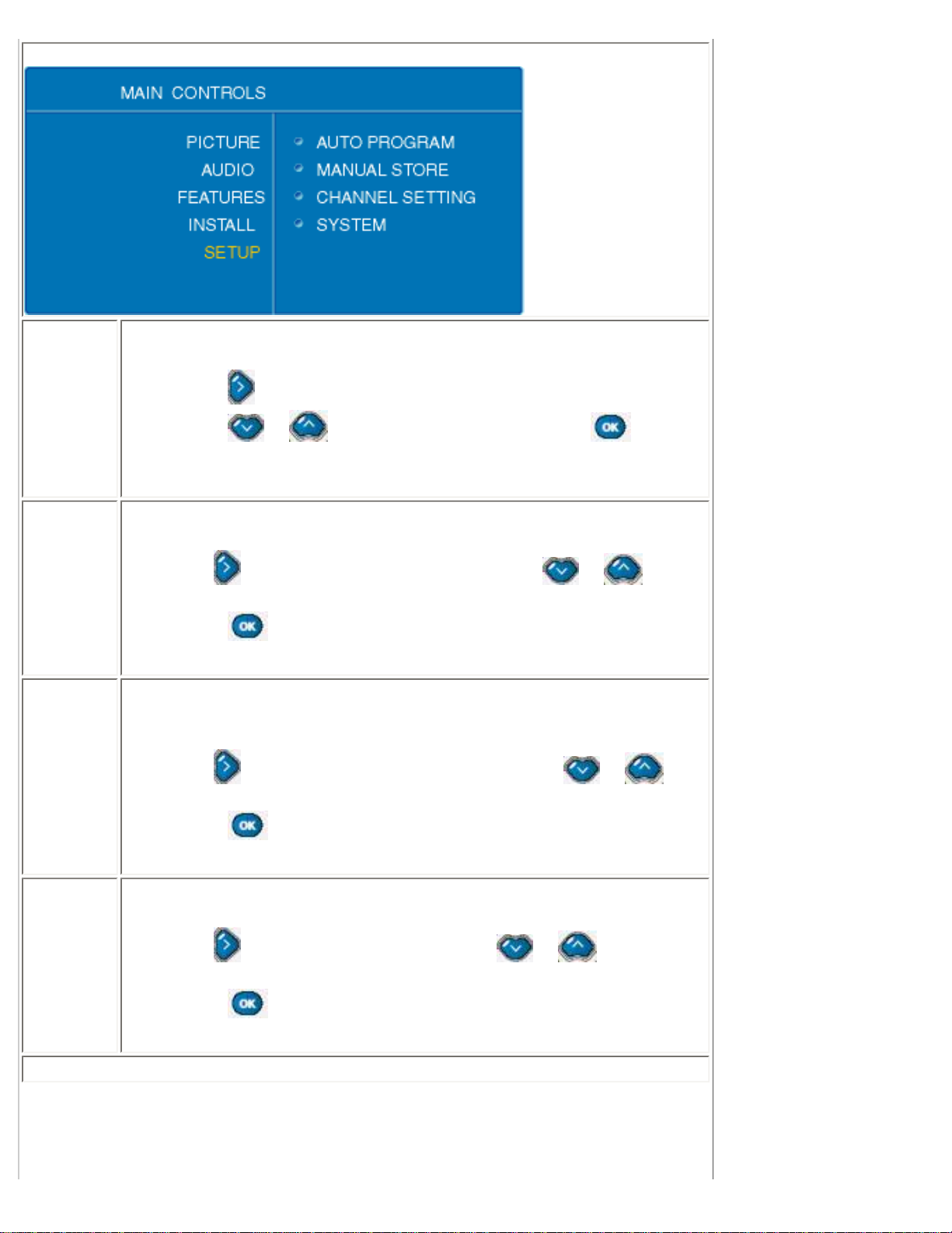
TV mode (Europe, Asia Pacific models)
Auto
Program
Scan all existing channels from your tuner input.
● Press to start.
● Press or to adjacent sub-menu selections, to return
to main menu.
Manual
Store
Select a frequency with specific channel.
● Use to enter Manual Store sub-menu, and or to
select between selections.
● Then, to confirm.
Channel
Setting
Choose channel setting to channel edit, channel swap, neme edit, and
channel sort.
● Use to enter Channel Setting sub-menu, and or to
select between selections.
● Then, to confirm.
System
Select different programs in TV mode.
● Use to enter System sub-menu, and or to select
between selections.
● Then, to confirm.
Manual Store sub-menu
file:///D|/My%20Documents/dfu/BDL4221V/english/420wn6/OSD/osddesc.htm (19 of 22)2005-11-07 12:54:53 PM
Page 40

On Screen Display
System
● Users can use or to toggle between
❍ France: scans pan Europe and French TV systems
❍ Western Europe: scans pan Europe TV systems only.
● Press or to adjacent sub-menu selections, to
confirm and return to upper level sub-menu.
Manual
Store
Select a frequency with specific channel.
● Use to enter, and use or to adjust frequency.
● Then, press or to adjacent sub-menu selections, to
confirm.
Program
Number
Give a channel number to the frequency chose in the above function.
● Use to enter, and use or to select a number.
● Press or to adjacent sub-menu selections, to
confirm.
Fine Tune
Fine tune the channel frequency to get a better display quality.
● Use to enter, and use or to adjust frequency.
● Then, press or to adjacent sub-menu
selections,
to confirm.
Store
● Use to enter storing process.
● A selection of Store? Yes/No will appear.
● Press or to toggle between
❍ Yes
❍ No
● Press to confirm and return to sub-menu.
file:///D|/My%20Documents/dfu/BDL4221V/english/420wn6/OSD/osddesc.htm (20 of 22)2005-11-07 12:54:53 PM
Page 41

On Screen Display
Channel
Edit
Choices to add or delete channels from available channels.
● Press enter Channel Edit sub-menu
● In Channel selection, use or to choose the channel that
you wish to add or delete.
● Then, press to next selection, use or to toggle
between
❍ Activate (add)
❍ Skip (delete)
● Repeat the above two steps to add or delete other channels, or,
● Press to confirm and return to upper level sub-menu
● Press or to adjacent sub-menu selections.
Channel
Swap
To swap channel numbers between two channels.So users can put
preferred channels at front.
● Users can use to enter Manual Store sub-menu,
● or to select between selections.
● Then, to confirm.
Channel Swap sub-menu
From
Choose a channel number to be swapped from.
● Use or to select channel.
● to confirm and return to upper level sub-menu.
To
Choose a target channel number to be swapped to.
● Use or to select channel.
● to confirm and return to upper level sub-menu.
Exchange
Execute channel swap.
● Users can use to execute the swapping move.
file:///D|/My%20Documents/dfu/BDL4221V/english/420wn6/OSD/osddesc.htm (21 of 22)2005-11-07 12:54:53 PM
Page 42

On Screen Display
Name Edit
Modify the channel name from a broadcaster give one to a user preferred
one.
● Users can use to enter
● Use or to select channel.
● Press to name input line.
● Use or to select from A to Z, or to adjacent
alphabet.
● Press to confirm and return to upper level sub-menu.
Channel
Sort
Sort channel name sequence in alphabetical order, from A to Z. Those
channels without a name will be placed at the end of the sequence
according to their frequencies, from small to large.
● Users can use to enter.
● Press to start sorting.
RETURN TO TOP OF THE PAGE
file:///D|/My%20Documents/dfu/BDL4221V/english/420wn6/OSD/osddesc.htm (22 of 22)2005-11-07 12:54:53 PM
Page 43

Remote Control
Remote Control
On Screen Display • Using Your Remote Control
Using Your Remote Control
file:///D|/My%20Documents/dfu/BDL4221V/english/420wn6/OSD/tv_control.htm (1 of 5)2005-11-07 12:54:56 PM
Page 44

Remote Control
1
AV source:
● To select TV/video source in TV and also PIP window.
● If TV is in Standby mode, press this button to switch to ON.
2
Mode:
Screen aspect ratio, switching between 4:3, 16: 9, wide screen, and super
wide.
3
Numerical keys:
● For direct access to programs.
● If TV is in Standby mode, press any number will switch the TV to ON
mode.
4
Previous program:
Jump to previous TV channel you are viewing.
5
Menu:
To turn on or off the On-screen-display (OSD) menu
6
● Move the cursor up in OS
● Channel up
7
● Move the cursor left in OSD
● Adjust volume down
8
Switching between PC and TV mode.
9
Closed Caption:
Functions in North America and Asia Pacific models only.
10
● Move the cursor down in OSD
● Channel down
file:///D|/My%20Documents/dfu/BDL4221V/english/420wn6/OSD/tv_control.htm (2 of 5)2005-11-07 12:54:56 PM
Page 45
Remote Control
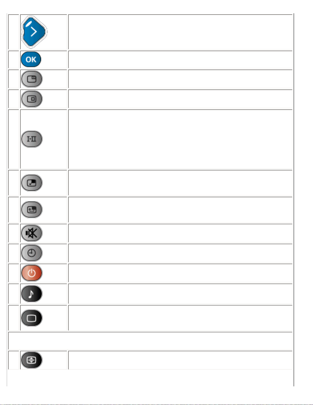
11
● Move the cursor right in OSD
● Adjust volume up
12
Confirm the chosen OSD function
13
Freeze:
Freeze the screen in video mode or PIP.
14
Status:
Display channel number, video/PC mode, and sound mode information.
15
Sound select:
● To switch between mono and stereo, or to choose between Dual I
and Dual II for bilingual transmissions.
● For TV sets fitted with NICAM, depends on transmission, you can
switch between NICAM stereo and Mono, or between NICAM Dual I,
NICAM Dual II, and Mono.
16
PIP Size:
Adjusts Picture-in-Picture (PIP) window size between small, medium, large,
picture-by-picture (PBP or split screen), and off.
17
PIP position:
Changing PIP window’s location on the screen between upper right, lower
right, lower left, and upper left.
18
Mute:
Disables audio: To enable audio, press the button again.
19
Sleep Timer:
Selects a period of time and the unit will switch off automatically.
20
Standby:
Sets the TV to standby mode temporary.
27
Smart Sound:
Chooses audio effects between Music, Theater, News, and Personal.
28
Smart Picture:
Choose picture settings between Sports, Movie, Weak signal, Night,
Multimedia, and Personal.
The following buttons are using in Teletext mode only, which are available in Europe and some
of the Asia Pacific TV systems.
21
Teletext Enlarge:
Enlarge teletext context to two times larger.
file:///D|/My%20Documents/dfu/BDL4221V/english/420wn6/OSD/tv_control.htm (3 of 5)2005-11-07 12:54:56 PM
Page 46

Remote Control
22
Teletext Mix:
Teletext background become transparent, content mixes with images.
23
Teletext On/Off:
Teletext ON or OFF.
24
Teletext Hold:
Freezes the teletext page.
25
Main Index:
Press the button to return to the main index.
26
Teletext Reveal/Conceal:
To view the concealed text information (e.g. question/answer, quiz, etc.)
send by the teletext provider. Press the button can toggle between conceal
and reveal mode.
These four color buttons allow you to access the item or the page indicated
by corresponding color in teletext.
Warning:
If you are going to control the monitor TV via RS232 interface, to avoid conflict, you
need to disable the remote control first. You can enter the OSD menu, select Install,
remote control to achieve so. After remote control is disabled, you can use buttons on
the unit to enter OSD and enable it, or enable remote control via RS232 command.
RETURN TO TOP OF THE PAGE
file:///D|/My%20Documents/dfu/BDL4221V/english/420wn6/OSD/tv_control.htm (4 of 5)2005-11-07 12:54:56 PM
Page 47

Customer Care and Warranty
Customer Care & Warranty
PLEASE SELECT YOUR COUNTRY/AREA TO REVIEW DETAILS OF YOUR
WARRANTY COVERAGE
WESTERN EUROPE: Austria • Belgium • Cyprus • Denmark • France • Germany • Greece •
Finland • Ireland • Italy • Luxembourg • the Netherlands • Norway • Portugal • Sweden •
Switzerland • Spain • United Kingdom
EASTERN EUROPE: Czech Republic • Hungary • Poland • Russia • Slovakia • Slovenia •
Turkey
LATIN AMERICA: Antilles • Argentina • Brasil • Chile • Colombia • Mexico • Paraguay •
Peru • Uruguay • Venezuela
NORTH AMERICA: Canada • USA
PACIFIC: Australia • New Zealand
ASIA: Bangladesh • China • Hong Kong • India • Indonesia • Japan • Korea • Malaysia •
Pakistan • Philippines • Singapore • Taiwan • Thailand
AFRICA: Morocco • South Africa
MIDDLE EAST: Dubai • Egypt
file:///D|/My%20Documents/dfu/BDL4221V/english/warranty/warranty.htm2005-11-07 12:54:59 PM
Page 48

Download and Print
Download and Print
Installing your LCD monitor driver • Download and Printing Instructions • Installing FPadjust
Program
Installing Your LCD monitor driver
System requirements:
●
PC running Windows® 95, Windows® 98, Windows® 2000 , Windows® Me, Windows® XP
or later
● Find your driver ".inf/.icm/.cat" at : /PC/drivers/
Read the "Readme.txt" file before installing.
This page provides an option to read the manual in .pdf format. PDF files can be downloaded into
your hard disk, then viewed and printed with Acrobat Reader or through your browser.
If you do not have Adobe¨ Acrobat Reader installed, click on the link to install the application.
Adobe® Acrobat Reader for PC / Adobe® Acrobat Reader for Mac.
Download instructions:
To download the file:
1. Click-and-hold your mouse over the icon below. (Win95/98/2000/Me/XP users right-click)
Download
BDL4221V.pdf
2. From the menu that appears, choose 'Save Link As...', 'Save Target As...' or 'Download Link to
Disk'.
file:///D|/My%20Documents/dfu/BDL4221V/english/download/download.htm (1 of 3)2005-11-07 12:55:01 PM
Page 49

Download and Print
3. Choose where you would like to save the file; click 'Save' (if prompted to save as either 'text' or
'source', choose 'source').
Printing instructions:
To print the manual:
1. With the manual file open, follow your printer's instructions and print the pages you need.
RETURN TO TOP OF THE PAGE
Installing FPadjust Program
The FP Adjust program generates alignment patterns which will help you adjust monitor settings
such as CONTRAST, BRIGHTNESS, HORIZONTAL & VERTICAL POSITION, PHASE and CLOCK.
System requirements:
●
PC running Windows® 95, Windows® 98, Windows® 2000, Windows® Me, Windows® XP
or later
To install FPadjust Program:
●
Click on the link or icon to install FPadjustment Program.
or
●
Click-and-hold your mouse over the icon. (Win95/98/2000/Me/XP users right-click)
file:///D|/My%20Documents/dfu/BDL4221V/english/download/download.htm (2 of 3)2005-11-07 12:55:01 PM
Page 50

Download and Print
Download
FP_setup04.exe
●
From the menu that appears, choose 'Save Link As...', 'Save Target As...' or 'Download Link
to Disk'.
● Choose where you would like to save the file; click 'Save' (if prompted to save as either 'text'
or 'source', choose 'source').
● Exit your browser and install the FPadjust Program.
Read the "FP_Readme04.txt" file before installing.
RETURN TO TOP OF THE PAGE
file:///D|/My%20Documents/dfu/BDL4221V/english/download/download.htm (3 of 3)2005-11-07 12:55:01 PM
Page 51

FAQs (Frequently Asked Questions)
FAQs (Frequently Asked Questions)
Safety and Troubleshooting • General FAQs • Screen Adjustments • Compatibility with
Other Peripherals • LCD Panel Technology • Ergonomics, Ecology and Safety Standards •
Troubleshooting • Regulatory Information • Other Related Information
General FAQs
Q:
When I install my monitor what should I do if the screen shows 'Cannot display this video
mode'?
A: Recommended video mode for Philips 42": 1360x768 @60Hz.
1. Unplug all cables, then connect your PC to the monitor that you used
previously.
2. In the Windows Start Menu, select Settings/Control Panel. In the Control Panel
Window, select the Display icon. Inside the Display Control Panel, select the
'Settings' tab. Under the setting tab, in box labeled 'desktop area', move the
slidebar to 1360x768 pixels (42").
3. Open 'Advanced Properties' and set the Refresh Rate to 60Hz, then click OK.
4. Restart your computer and repeat step 2 and 3 to verify that your PC is set at
1360x768@60Hz (42").
5. Shut down your computer, disconnect your old monitor and reconnect your
Philips LCD monitor.
6. Turn on your monitor and then turn on your PC.
Q: What should I do when screen shows: THIS IS 85HZ OVERSCAN, CHANGE COMPUTER
DISPLAY INPUT TO 1360 x 768 @60HZ?
A: It means the signal input from your PC is 85Hz -- outside the range that the
monitor can display. New Generation LCD intelligent monitor capabilities temporarily
override the overscan, providing you with 10 minutes to reset timing to recommended
settings.
Here's how:
file:///D|/My%20Documents/dfu/BDL4221V/english/420wn6/SAFETY/SAF_FAQ.HTM (1 of 9)2005-11-07 12:55:06 PM
Page 52

FAQs (Frequently Asked Questions)
Go to your Windows Start menu. Select Settings, then Control Panel. Select Display.
Move to Settings and click on the Advanced button. Under Adaptor, change the
refresh rate to 56~75.
You have 10 minutes to complete the operation; if you do not complete within 10
minutes, power off and re-power on monitor to enter changes.
Q: What does 'refresh rate' mean in connection with an LCD monitor?
A: The refresh rate is of much less relevance for LCD monitors. LCD monitors display
a stable, flicker-free image at 60Hz. There is no visible difference between 85Hz and
60Hz.
Q: What are the .inf and .icm files on the CD-ROM? How do I install the drivers (.inf and .
icm)?
A: These are the driver files for your monitor. Follow the instructions in your user
manual to install the drivers. Your computer may ask you for monitor drivers (.inf and .
icm files) or a driver disk when you first install your monitor. Follow the instructions to
insert the ( companion CD-ROM) included in this package. Monitor drivers (.inf and .
icm files) will be installed automatically.
Q: How do I adjust the resolution?
A: Your video card/graphic driver and monitor together determine the available
resolutions. You can select the desired resolution under Windows® Control Panel
with the "Display properties"
.
Q: What if I get lost when I am making monitor adjustments?
A: Simply press the OK button, then select 'Reset' to recall all of the original factory
settings.
file:///D|/My%20Documents/dfu/BDL4221V/english/420wn6/SAFETY/SAF_FAQ.HTM (2 of 9)2005-11-07 12:55:06 PM
Page 53

FAQs (Frequently Asked Questions)
Q: What is the Auto function?
A: The AUTO adjustment key restores the optimal screen position, phase and clock
settings at the press of a single button – without the need to navigate through OSD
menus and control keys.
Note: Auto function is available in selected models only.
Q: My Monitor has no power (Power LED does not light up). What should I do?
A: Make sure the AC power cord is connected to the Monitor.
Q: Will the LCD monitor accept an interlaced signal under PC models?
A: No. If an Interlace signal is used, the screen displays both odd and even horizontal
scanning lines at the same time, thus distorting the picture.
Q: What does the Refresh Rate mean for LCD?
A: Unlike CRT display technology, in which the speed of the electron beam is swept
from the top to the bottom of the screen determines flicker, an active matrix display
uses an active element (TFT) to control each individual pixel and the refresh rate is
therefore not really applicable to LCD technology.
Q: Will the LCD screen be resistant to scratches?
A: A protective coating is applied to the surface of the LCD, which is durable to a
certain extent (approximately up to the hardness of a 2H pencil). In general, it is
recommended that the panel surface is not subject to any excessive shocks or
scratches. An optional protective cover with greater scratch resistance is also
available.
file:///D|/My%20Documents/dfu/BDL4221V/english/420wn6/SAFETY/SAF_FAQ.HTM (3 of 9)2005-11-07 12:55:06 PM
Page 54

FAQs (Frequently Asked Questions)
Q: How should I clean the LCD surface?
A: For normal cleaning, use a clean, soft cloth. For extensive cleaning, please use
isopropyl alcohol. Do not use other solvents such as ethyl alcohol, ethanol, acetone,
hexane, etc.
Q: Can the Philips LCD Monitor be mounted on the wall or used as a touch panel?
A: Yes. Philips LCD monitors have this optional feature. The standard VESA mount
holes on the back cover allows the user to mount the Philips monitor on any VESA
standard ARM or accessories. Touch panels are being developed for future
applications. Check with your Philips sales representative for more information.
RETURN TO TOP OF THE PAGE
Screen Adjustments
Q:
What is the FPadjust program on the CD-ROM?
A: The FPadjust program generates alignment patterns that help you adjust monitor
settings such as Contrast, Brightness, Horizontal Position, Vertical Position, Phase
and Clock for optimal performance.
Q: When I install my monitor, how do I get the best performance from the monitor?
A:
1.
For best performance, make sure your display settings are set at
1360x768@60Hz for 42". Note: You can check the current display settings by
pressing the OSD OK button once. The current display mode is shown in
product information in OSD main controls.
2. To install the Flat Panel Adjust (FPadjust) program located on the monitor
setup CD-ROM, open the CD-ROM and double-click the FP_setup04.exe icon.
This will install FP Adjust automatically and place a shortcut on your desktop.
3. Run FPadjust by double clicking the shortcut. Follow the instructions step by
step to optimize image performance with your system's video controller.
file:///D|/My%20Documents/dfu/BDL4221V/english/420wn6/SAFETY/SAF_FAQ.HTM (4 of 9)2005-11-07 12:55:06 PM
Page 55

FAQs (Frequently Asked Questions)
Q: How do LCDs compare to CRTs in terms of radiation?
A: Because LCDs do not use an electron gun, they do not generate the same amount
of radiation at the screen surface.
RETURN TO TOP OF THE PAGE
Compatibility with other Peripherals
Q:
Can I connect my LCD monitor to any PC, workstation or Mac?
A: Yes. All Philips LCD monitors are fully compatible with standard PCs, Macs and
workstations. You may need a cable adapter to connect the monitor to your Mac
system. Please contact your dealer/retailer for more information.
Q: Are Philips LCD monitors Plug-and-Play?
A: Yes, the monitors are Plug-and-Play compatible with Windows® 95, 98, 2000 and
XP.
Q: What is USB (Universal Serial Bus)?
A: Think of USB as a smart plug for PC peripherals. USB automatically determines
resources (like driver software and bus bandwidth) required by peripherals. USB
makes necessary resources available without user intervention. There are three main
benefits of USB. USB eliminates "case anxiety," the fear of removing the computer
case to install circuit board cards -- that often requires adjustment of complicated IRQ
settings -- for add-on peripherals. USB does away with "port gridlock." Without USB,
PCs are normally limited to one printer, two Com port devices (usually a mouse and
modem), one Enhanced Parallel Port add-on (scanner or video camera, for example),
and a joystick. More and more peripherals for multimedia computers come on the
market every day. With USB, up to 127 devices can run simultaneously on one
computer. USB permits "hot plug-in." No need to shut down, plug in, reboot and run
file:///D|/My%20Documents/dfu/BDL4221V/english/420wn6/SAFETY/SAF_FAQ.HTM (5 of 9)2005-11-07 12:55:06 PM
Page 56

FAQs (Frequently Asked Questions)
set up to install peripherals. No need to go through the reverse process to unplug a
device. Bottom line: USB transforms today's "Plug-and-Pray" into true Plug-and-Play!
Please refer to glossary for more information about USB.
Q: What is a USB hub ?
A: A USB hub provides additional connections to the Universal Serial Bus. A hub's
upstream port connects a hub to the host, usually a PC. Multiple downstream ports in
a hub allows connection to another hub or device, such as a USB keyboard, camera
or printer.
RETURN TO TOP OF THE PAGE
LCD Panel Technology
Q:
What is a Liquid Crystal Display?
A: A Liquid Crystal Display (LCD) is an optical device that is commonly used to
display ASCII characters and images on digital items such as watches, calculators,
portable game consoles, etc. LCD is the technology used for displays in notebooks
and other small computers. Like light-emitting diode and gas-plasma technologies,
LCD allows displays to be much thinner than cathode ray tube (CRT) technology.
LCD consumes much less power than LED and gas-displays because it works on the
principle of blocking light rather than emitting it.
Q: How are LCDs made?
A: LCDs are created from two glass plates separated from each other at a distance
of a few microns. The plates are filled with liquid crystal and then sealed together.
The top plate is colored with an RGB pattern to make the color filter. Polarizers are
then glued to both plates. This combination is sometimes called 'glass' or 'cell.' The
LCD cell is assembled into a 'module' by adding the backlight, driver electronics and
frame.
Q: What is polarization ?
file:///D|/My%20Documents/dfu/BDL4221V/english/420wn6/SAFETY/SAF_FAQ.HTM (6 of 9)2005-11-07 12:55:06 PM
Page 57

FAQs (Frequently Asked Questions)
A: Polarization is basically directing light to shine in one direction. Light is
electromagnetic waves. Electric and magnetic fields oscillate in a direction
perpendicular to the propagation of the light beam. The direction of these fields is
called the 'polarization direction'. Normal or non-polarized light has fields in several
directions; polarized light has a field in only one direction.
Q: What differentiates passive matrix LCDs from active matrix LCDs?
A: An LCD is made with either a passive matrix or an active matrix display grid. An
active matrix has a transistor located at each pixel intersection, requiring less current
to control the luminance of a pixel. For this reason, the current in an active matrix
display can be switched on and off more frequently, improving the screen refresh time
(your mouse pointer will appear to move more smoothly across the screen, for
example). The passive matrix LCD has a grid of conductors with pixels located at
each intersection in the grid.
Q: How does a TFT LCD Panel work?
A: On each column and row of the TFT LCD panel, a data source drive and a gate
drive are attached, respectively. The TFT drain of each cell is connected to the
electrode. The molecular arrangement of liquid crystal elements differ according to
whether it is impressed with voltage or not. It varies the direction of polarized light and
the amount of light by letting it through different arrays of liquid crystal elements.
When two polarized filters are arranged vertically on a polarized light pole, the light
that passes through the upper polarized panel is turned 90 degrees along with the
spiral structure of the liquid crystal molecules and goes through the polarized filter at
the bottom. When impressed with voltage, liquid crystal molecules are arranged
vertically from the original spiral structure and the direction of the light is not turned
through 90 degrees. In this case, light that comes through the top polarized panel
may not go through the polarized panel at the bottom.
Q: What are the advantages of TFT LCD compared with CRT?
A: In a CRT monitor, a gun shoots electrons and general light by colliding polarized
electrons on fluorescent glass. Therefore, CRT monitors basically operate with an
analog RGB signal. A TFT LCD monitor is a device that displays an input image by
operating a liquid crystal panel. The TFT has a fundamentally different structure than
a CRT: Each cell has an active matrix structure and independent active elements. A
TFT LCD has two glass panels and the space between them is filled with liquid
file:///D|/My%20Documents/dfu/BDL4221V/english/420wn6/SAFETY/SAF_FAQ.HTM (7 of 9)2005-11-07 12:55:06 PM
Page 58

FAQs (Frequently Asked Questions)
crystal. When each cell is connected with electrodes and impressed with voltage, the
molecular structure of the liquid crystal is altered and controls the amount of inlet
lighting to display images. A TFT LCD has several advantages over a CRT, since it
can be very thin and no flickering occurs because it does not use the scanning
method.
Q: Why is vertical frequency of 60Hz optimal for an LCD monitor?
A: Unlike a CDT monitor, the TFT LCD panel has a fixed resolution. For example, an
XGA monitor has 1024x3 (R, G, B) x 768 pixels and a higher resolution may not be
available without additional software processing. The panel is designed to optimize
the display for a 65MHz dot clock, one of the standards for XGA displays. Since the
vertical/horizontal frequency for this dot clock is 60Hz/48kHz, the optimum frequency
for this monitor is 60Hz.
Q: What kind of wide-angle technology is available? How does it work?
A: The TFT LCD panel is an element that controls/displays the inlet of a backlight
using the dual-refraction of a liquid crystal. Using the property that the projection of
inlet light refracts toward the major axis of the liquid element, it controls the direction
of inlet light and displays it. Since the refraction ratio of inlet light on liquid crystal
varies with the inlet angle of the light, the viewing angle of a TFT is much narrower
than that of a CDT. Usually, the viewing angle refers to the point where the contrast
ration is 10. Many ways to widen the viewing angle are currently being developed and
the most common approach is to use a wide viewing angle film, which widens the
viewing angle by varying the refraction ratio. IPS (In Plane Switching) or MVA (Multi
Vertical Aligned) is also used to give a wider viewing angle.
Q: Why is there no flicker on an LCD Monitor?
A: Technically speaking, LCDs do flicker, but the cause of the phenomenon is
different from that of a CRT monitor -- and it has no impact of the ease of viewing.
Flickering in an LCD monitor relates to usually undetectable luminance caused by the
difference between positive and negative voltage. On the other hand, CRT flickering
that can irritate the human eye occurs when the on/off action of the fluorescent object
becomes visible. Since the reaction speed of liquid crystal in an LCD panel is much
slower, this troublesome form of flickering is not present in an LCD display.
Q: Why is an LCD monitor virtually free of Electro Magnetic Interference?
file:///D|/My%20Documents/dfu/BDL4221V/english/420wn6/SAFETY/SAF_FAQ.HTM (8 of 9)2005-11-07 12:55:06 PM
Page 59

FAQs (Frequently Asked Questions)
A: Unlike a CRT, an LCD monitor does not have key parts that generate Electro
Magnetic Interference, especially magnetic fields. Also, since an LCD display utilizes
relatively low power, its power supply is extremely quiet.
RETURN TO TOP OF THE PAGE
Ergonomics, Ecology and Safety Standards
Q:
What is the CE mark?
A: The CE (Conformité Européenne) mark is required to be displayed on all regulated
products offered for sale on the European market. This 'CE' mark means that a
product complies with the relevant European Directive. A European Directive is a
European 'Law' that relates to health, safety, environment and consumer protection,
much the same as the U.S. National Electrical Code and UL Standards.
Q: Does the LCD monitor conform to general safety standards?
A: Yes. Philips LCD monitors conform to the guidelines of MPR-II and TCO 99/03
standards for the control of radiation, electromagnetic waves, energy reduction,
electrical safety in the work environment and recyclability. The specification page
provides detailed data on safety standards.
More information is provided in the Regulatory Information section.
RETURN TO TOP OF THE PAGE
file:///D|/My%20Documents/dfu/BDL4221V/english/420wn6/SAFETY/SAF_FAQ.HTM (9 of 9)2005-11-07 12:55:06 PM
Page 60

Troubleshooting
Troubleshooting
Safety and Troubleshooting • FAQs • Common Problems • TV and Audio Problems • Video
Problems • Remote Control Problems • Product Specific Problems • OSD Warning Message
• Regulatory Information • Other Related Information
This page deals with problems that can be corrected by the user. If the problem still persists after
you have tried these solutions, contact your nearest Philips dealer.
Common Problems
Symptoms
Having this
problem?
Check these items
No Video/ Power
LED off
No picture, the
LCD Monitor TV is
not working
● Check connection integrity at both ends of the
video cable and/or power cord.
● Electric outlet verification
● Ensure AC power at the rear of the monitor
TV is switched on.
No Video/ Power
LED on
No picture or no
brightness
● Increase brightness and contrast controls.
● Perform the LCD Monitor TV self-test feature
check.
● Check for bent or broken pins in video cable
connector.
Poor Focus Picture is fuzzy,
blurry or ghosting
● Auto adjust image through Menu -> Image
Setting -> Auto Adjust.
● Adjust Phase and Clock controls via OSD.
● Eliminate video extension cables.
● Perform the LCD Monitor TV factory reset (via
Menu -> Factory Reset -> All Settings).
● Lower video resolution or increase font size.
file:///D|/My%20Documents/dfu/BDL4221V/english/420wn6/SAFETY/saf_troub.htm (1 of 7)2005-11-07 12:55:07 PM
Page 61

Troubleshooting
Shaky/Jittery Video Wavy picture or
fine movement
● Auto adjust image through Menu -> Image
Setting -> Auto Adjust
● Adjust Phase and Clock controls via OSD
● Perform the LCD Monitor TV factory reset (via
Menu -> Factory Reset -> All Settings)
● Check environmental factors
● Relocate and test in other room
Missing Pixels LCD screen has
spots
● Cycle power on-off
● These are pixels that are permanently off and
is a natural defect that occurs in LCD
technology
Stuck-on Pixels LCD screen has
bright spots
● Cycle power on-off
● These are pixels that are permanently on and
is a natural defect that occurs in LCD
technology
Brightness Problems Picture too dim or
too bright
● Perform the LCD Monitor TV factory reset (via
Menu -> Factory Reset -> All Settings)
● Auto adjust image through Menu -> Image
Setting -> Auto Adjust
● Adjust brightness & contrast controls
Note: When operating in DVI mode, the
contrast adjustment is not available.
Geometric Distortion Screen not
centered correctly
● Perform the LCD Monitor TV reset on
"Position Settings Only"
● Auto adjust image through Menu -> Image
Setting -> Auto Adjust
● Adjust the centering controls
● Ensure the LCD Monitor TV is in proper video
mode
Note: When operating in DVI mode, the
positioning adjustments are not
available.
file:///D|/My%20Documents/dfu/BDL4221V/english/420wn6/SAFETY/saf_troub.htm (2 of 7)2005-11-07 12:55:07 PM
Page 62

Troubleshooting
Horizontal/Vertical
Lines
Screen has one or
more lines
● Perform the LCD Monitor TV reset
● Auto adjust image through Menu -> Image
Setting -> Auto Adjust
● Adjust Phase and Clock controls via OSD
● Check for bent or broken pins in the video
cable connector
Note: When operating in DVI mode, the
Pixel Clock and Phase adjustments are
not available.
Sync Problems Screen is
scrambled or
appears torn
● Perform the LCD Monitor TV reset
● Push Auto Adjust button
● Adjust Phase and Clock controls via OSD
● Check for bent or broken pins
● Boot up in the "safe mode"
LCD Scratched Screen has
scratches or
smudges
● Turn the LCD Monitor TV off and clean the
screen
Safety Related
Issues
Visible signs of
smoke or sparks
● Do not perform any troubleshooting steps
● The LCD Monitor TV needs to be replaced
Intermittent Problems The LCD Monitor
TV malfunctions
on & off
● Ensure the LCD Monitor TV is in proper video
mode
● Ensure video cable connection between
computer and the LCD monitor TV is secured
● Perform the LCD Monitor TV factory reset (via
Menu -> Factory Reset -> All Settings)
● Perform the LCD Monitor TV self-test feature
check to determine if the intermittent problem
occurs in self-test mode
TV and Audio Problems
file:///D|/My%20Documents/dfu/BDL4221V/english/420wn6/SAFETY/saf_troub.htm (3 of 7)2005-11-07 12:55:07 PM
Page 63

Troubleshooting
Poor TV signal
reception
Abnormal picture
seen from the
screen
● The proximity of mountains or high buildings
may be responsible for ghost pictures,
echoing or shadows. In this case, try manually
adjusting your pictures: see 'fine tuning' or
adjust the direction of the outside aerial.
No TV picture
No picture when
TV input was
selected
● Have you connected the aerial socket
properly? Have you chosen the right system?
Poorly connected SCART cables or aerial
sockets are often the cause of picture or
sound problems (sometimes the connectors
can become half disconnected if the LCD
Monitor TV set is moved or turned). Check all
connections.
No sound
No sound output
when a program
with sound was
playing
● Ensure that the audio cables are firmly
connected to both the audio input connectors
on your the LCD Monitor TV and audio output
connectors on your PC or Video player.
● If on certain TV channels you receive a
picture but no sound, this means that you do
not have the correct TV system. Modify the
SYSTEM setting.
Video Problems
No Video
No signal indicator
is displayed.
● Check Video Input Selection
❍ Composite: Yellow colored RCA jack
❍ S-Video: Typically a round 4 pin jack
❍ Component: Typically 3 RCA jacks of
Green, Red and Blue.
● Make sure you did not plug the video cable to
video output port behind the LCD monitor TV.
Low Quality DVD
playback
Picture not crisp
and some color
distortion
● Check DVD connection
❍ Composite gives good picture
❍ S-Video gives better picture
❍ Component gives best picture
file:///D|/My%20Documents/dfu/BDL4221V/english/420wn6/SAFETY/saf_troub.htm (4 of 7)2005-11-07 12:55:07 PM
Page 64

Troubleshooting
No sound
See video but no
audio
● Check if the LCD Monitor TV volume is turn
off of muted.
● Connect the audio cable securely.
● Audio cable is connected incorrectly.
● Verify that the audio source is selected
correctly in the OSD.
Remote Control Problems
Remote control does
not work properly
No response from
the LCD Monitor
TV when remote
is pressed
● Point the remote control directly at the remote
sensor on the LCD Monitor TV.
● Replace both batteries with new ones.
● Make sure the remote control is not disabled
(for disable/enable the remote control, please
refer to the section of Remote Control).
Product Specific Problems
Screen image is too
small
Image is centered
on screen, but
does not fill entire
viewing area
● Perform the LCD Monitor TV factory reset (via
Menu -> Factory Reset -> All Settings).
Cannot adjust the
LCD Monitor TV with
the buttons at the
side of the unit
OSD does not
appear on the
screen
● Turn the LCD Monitor TV off and unplug the
power cord and then plug back and power on.
For further assistance, refer to the Consumer Information Centers list and contact your local
Philips distributor.
RETURN TO TOP OF THE PAGE
OSD Warning Messages
A warning message may appear on the screen indicating the LCD Monitor TV current status.
file:///D|/My%20Documents/dfu/BDL4221V/english/420wn6/SAFETY/saf_troub.htm (5 of 7)2005-11-07 12:55:07 PM
Page 65

Troubleshooting
When user sees this warning message, it means
that the LCD Monitor TV is in adjustment process.
A warning message may appear on the screen
indicating that the LCD Monitor TV is out of sync
range.
See Specifications for the Horizontal and Vertical
frequency ranges addressable by this the LCD
Monitor TV. Recommended mode is 1360 x 768
@ 60Hz.
This message means that there is no video input
signal.
The LCD Monitor TV is in a power saving mode
(in PC mode).
The main OSD menu is unlocked.
The main OSD menu is locked.
file:///D|/My%20Documents/dfu/BDL4221V/english/420wn6/SAFETY/saf_troub.htm (6 of 7)2005-11-07 12:55:07 PM
Page 66

Troubleshooting
RETURN TO TOP OF THE PAGE
file:///D|/My%20Documents/dfu/BDL4221V/english/420wn6/SAFETY/saf_troub.htm (7 of 7)2005-11-07 12:55:07 PM
Page 67

Regulatory Information
Regulatory Information
CE Declaration of Conformity • Display Power Management Signaling • Federal Communications
Commission (FCC) Notice (U.S. Only) • Commission Federale de la Communication (FCC
Declaration) • EN 55022 Compliance (Czech Republic Only) • VCCI Class 2 Notice (Japan Only) •
MIC Notice (South Korea Only) • Polish Center for Testing and Certification Notice • North Europe
(Nordic Countries) Information • BSMI Notice (Taiwan Only) • Ergonomie Hinweis (nur Deutschland)
• Philips End-of-Life Disposal • Information for UK only • Waste Electrical and Electronic Equipment-
WEEE
Safety and Troubleshooting • Troubleshooting • Other Related Information • Frequently Asked
Questions (FAQs)
CE Declaration of Conformity
Philips Consumer Electronics declare under our responsibility that the product is in conformity with the
following standards
- EN60950-1:2001 (Safety requirement of Information Technology Equipment)
- EN55022:1998 (Radio Disturbance requirement of Information Technology Equipment)
- EN55024:1998 (Immunity requirement of Information Technology Equipment)
- EN61000-3-2:2000 (Limits for Harmonic Current Emission)
- EN61000-3-3:1995 (Limitation of Voltage Fluctuation and Flicker)
- EN55013:1990+A12+A13+A14 (Radio Disturbance requirement of Sound and Television Receivers and
associated)
- EN55020:1994+A12 (Immunity requirement of Sound and Television Receivers and associated)
- IEC Guide 112:2000 ( Guide on the Safety of Multimedia Equipment) following provisions of directives
applicable
- 73/23/EEC (Low Voltage Directive)
- 89/336/EEC (EMC Directive)
- 93/68/EEC (Amendment of EMC and Low Voltage Directive)
and is produced by a manufacturing organization on ISO9000 level.
The product also comply with the following standards
- ISO9241-3, ISO9241-7, ISO9241-8 (Ergonomic requirement for Visual Display)
- ISO13406-2 (Ergonomic requirement for Flat panels)
- GS EK1-2000 (GS specification)
- prEN50279:1998 (Low Frequency Electric and Magnetic fields for Visual Display)
- MPR-II (MPR:1990:8/1990:10 Low Frequency Electric and Magnetic fields)
- TCO99, TCO03 (Requirement for Environment Labelling of Ergonomics, Energy, Ecology and Emission,
TCO: Swedish Confederation of Professional Employees) for TCO versions
file:///D|/My%20Documents/dfu/BDL4221V/english/420wn6/SAFETY/REGS/REGULAT.HTM (1 of 11)2005-11-07 12:55:08 PM
Page 68

Regulatory Information
RETURN TO TOP OF THE PAGE
Display Power Management Signaling
BDL4221V
This monitor is equipped with a function for saving energy which supports the VESA Display
Power Management Signaling (DPMS) standard. This means that the monitor must be
connected to a computer which supports VESA DPMS to fulfill the requirements in the NUTEK
specification 803299/94. Time settings are adjusted from the system unit by software.
NUTEK VESA State LED Indicator Power Consumption
Normal operation ON Blue 100 W (typical)
Power Saving
Alternative 2
One step
OFF(Sleep) Amber < 5 W
Switch OFF OFF < 3 W
We recommend you switch off the monitor when it is not in use for quite a long time.
RETURN TO TOP OF THE PAGE
Federal Communications Commission (FCC) Notice (U.S. Only)
file:///D|/My%20Documents/dfu/BDL4221V/english/420wn6/SAFETY/REGS/REGULAT.HTM (2 of 11)2005-11-07 12:55:08 PM
Page 69

Regulatory Information
This equipment has been tested and found to comply with the limits for a Class B
digital device, pursuant to Part 15 of the FCC Rules. These limits are designed to
provide reasonable protection against harmful interference in a residential
installation. This equipment generates, uses and can radiate radio frequency energy
and, if not installed and used in accordance with the instructions, may cause harmful
interference to radio communications. However, there is no guarantee that
interference will not occur in a particular installation. If this equipment does cause
harmful interference to radio or television reception, which can be determined by
turning the equipment off and on, the user is encouraged to try to correct the
interference by one or more of the following measures:
● Reorient or relocate the receiving antenna.
● Increase the separation between the equipment and receiver.
● Connect the equipment into an outlet on a circuit different from that to which the receiver is connected.
● Consult the dealer or an experienced radio/TV technician for help.
Changes or modifications not expressly approved by the party responsible for
compliance could void the user's authority to operate the equipment.
Use only RF shielded cable that was supplied with the monitor when connecting this monitor to a computer
device.
To prevent damage which may result in fire or shock hazard, do not expose this appliance to rain or
excessive moisture.
THIS CLASS B DIGITAL APPARATUS MEETS ALL REQUIREMENTS OF THE CANADIAN
INTERFERENCE-CAUSING EQUIPMENT REGULATIONS.
RETURN TO TOP OF THE PAGE
Commission Federale de la Communication (FCC Declaration)
file:///D|/My%20Documents/dfu/BDL4221V/english/420wn6/SAFETY/REGS/REGULAT.HTM (3 of 11)2005-11-07 12:55:08 PM
Page 70

Regulatory Information
Cet équipement a été testé et déclaré conforme auxlimites des appareils numériques
de class B,aux termes de l'article 15 Des règles de la FCC. Ces limites sont conçues
de façon à fourir une protection raisonnable contre les interférences nuisibles dans le
cadre d'une installation résidentielle. CET appareil produit, utilise et peut émettre des
hyperfréquences qui, si l'appareil n'est pas installé et utilisé selon les consignes
données, peuvent causer des interférences nuisibles aux communications radio.
Cependant, rien ne peut garantir l'absence d'interférences dans le cadre d'une
installation particulière. Si cet appareil est la cause d'interférences nuisibles pour la
réception des signaux de radio ou de télévision, ce qui peut être décelé en fermant
l'équipement, puis en le remettant en fonction, l'utilisateur pourrait essayer de
corriger la situation en prenant les mesures suivantes:
● Réorienter ou déplacer l'antenne de réception.
● Augmenter la distance entre l'équipement et le récepteur.
● Brancher l'équipement sur un autre circuit que celui utilisé par le récepteur.
● Demander l'aide du marchand ou d'un technicien chevronné en radio/télévision.
Toutes modifications n'ayant pas reçu l'approbation des services compétents en
matière de conformité est susceptible d'interdire à l'utilisateur l'usage du présent
équipement.
N'utiliser que des câbles RF armés pour les connections avec des ordinateurs ou périphériques.
CET APPAREIL NUMERIQUE DE LA CLASSE B RESPECTE TOUTES LES EXIGENCES DU REGLEMENT
SUR LE MATERIEL BROUILLEUR DU CANADA.
RETURN TO TOP OF THE PAGE
EN 55022 Compliance (Czech Republic Only)
file:///D|/My%20Documents/dfu/BDL4221V/english/420wn6/SAFETY/REGS/REGULAT.HTM (4 of 11)2005-11-07 12:55:08 PM
Page 71

Regulatory Information
RETURN TO TOP OF THE PAGE
VCCI Notice (Japan Only)
This is a Class B product based on the standard of the Voluntary Control Council for Interference (VCCI) for
Information technology equipment. If this equipment is used near a radio or television receiver in a domestic
environment, it may cause radio Interference. Install and use the equipment according to the instruction
manual.
Class B ITE
RETURN TO TOP OF THE PAGE
MIC Notice (South Korea Only)
Class B Device
file:///D|/My%20Documents/dfu/BDL4221V/english/420wn6/SAFETY/REGS/REGULAT.HTM (5 of 11)2005-11-07 12:55:08 PM
Page 72
Regulatory Information
Please note that this device has been approved for non-business purposes and may be used in any
environment, including residential areas.
RETURN TO TOP OF THE PAGE
Polish Center for Testing and Certification Notice
The equipment should draw power from a socket with an attached protection circuit (a three-prong socket).
All equipment that works together (computer, monitor, printer, and so on) should have the same power supply
source.
The phasing conductor of the room's electrical installation should have a reserve short-circuit protection
device in the form of a fuse with a nominal value no larger than 16 amperes (A).
To completely switch off the equipment, the power supply cable must be removed from the power supply
socket, which should be located near the equipment and easily accessible.
A protection mark "B" confirms that the equipment is in compliance with the protection usage requirements of
standards PN-93/T-42107 and PN-89/E-06251.
file:///D|/My%20Documents/dfu/BDL4221V/english/420wn6/SAFETY/REGS/REGULAT.HTM (6 of 11)2005-11-07 12:55:08 PM
Page 73

Regulatory Information
RETURN TO TOP OF THE PAGE
North Europe (Nordic Countries) Information
Placering/Ventilation
VARNING:
FÖRSÄKRA DIG OM ATT HUVUDBRYTARE OCH UTTAG ÄR LÄTÅTKOMLIGA, NÄR
DU STÄLLER DIN UTRUSTNING PÅPLATS.
Placering/Ventilation
ADVARSEL:
SØRG VED PLACERINGEN FOR, AT NETLEDNINGENS STIK OG STIKKONTAKT
ER NEMT TILGÆNGELIGE.
Paikka/Ilmankierto
VAROITUS:
SIJOITA LAITE SITEN, ETTÄ VERKKOJOHTO VOIDAAN TARVITTAESSA HELPOSTI
IRROTTAA PISTORASIASTA.
Plassering/Ventilasjon
ADVARSEL:
NÅR DETTE UTSTYRET PLASSERES, MÅ DU PASSE PÅ AT KONTAKTENE FOR
STØMTILFØRSEL ER LETTE Å NÅ.
file:///D|/My%20Documents/dfu/BDL4221V/english/420wn6/SAFETY/REGS/REGULAT.HTM (7 of 11)2005-11-07 12:55:08 PM
Page 74
Regulatory Information
RETURN TO TOP OF THE PAGE
BSMI Notice (Taiwan Only)
RETURN TO TOP OF THE PAGE
Ergonomie Hinweis (nur Deutschland)
Damit Ihr Monitor immer den in der Zulassung geforderten Werten entspricht, ist darauf zu achten, daß
1. Reparaturen nur durch Fachpersonal durchgeführt werden.
2. nur original-Ersatzteile verwendet werden.
3. bei Ersatz der Bildröhre nur eine bauartgleiche eingebaut wird.
Aus ergonomischen Gründen wird empfohlen, die Grundfarben Blau und Rot nicht auf dunklem
Untergrund zu verwenden (schlechte Lesbarkeit und erhöhte Augenbelastung bei zu geringem
Zeichenkontrast wären die Folge).
Der arbeitsplatzbezogene Schalldruckpegel nach DIN 45 635 beträgt 70dB (A) oder weniger.
ACHTUNG: BEIM AUFSTELLEN DIESES GERÄTES DARAUF ACHTEN, DAß
NETZSTECKER UND NETZKABELANSCHLUß LEICHT ZUGÄNGLICH SIND.
RETURN TO TOP OF THE PAGE
End-of-Life Disposal
Your new monitor contains materials that can be recycled and reused. Specialized companies can recycle
file:///D|/My%20Documents/dfu/BDL4221V/english/420wn6/SAFETY/REGS/REGULAT.HTM (8 of 11)2005-11-07 12:55:08 PM
Page 75

Regulatory Information
your product to increase the amount of reusable materials and to minimize the amount to be disposed of.
Please find out about the local regulations on how to dispose of your old monitor from your local Philips
dealer.
(For customers in Canada and U.S.A.)
This product may contain lead and/or mercury. Dispose of in accordance to local-state and federal
regulations.
For additional information on recycling contact www.eia.org (Consumer Education Initiative)
RETURN TO TOP OF THE PAGE
Information for UK only
WARNING - THIS APPLIANCE MUST BE
EARTHED.
Important:
This apparatus is supplied with an approved
moulded 13A plug. To change a fuse in this type
of plug proceed as follows:
1. Remove fuse cover and fuse.
2. Fit new fuse which should be a BS 1362 5A,A.
S.T.A. or BSI approved type.
3. Refit the fuse cover.
If the fitted plug is not suitable for your socket
outlets, it should be cut off and an appropriate 3pin plug fitted in its place.
If the mains plug contains a fuse, this should
have a value of 5A. If a plug without a fuse is
used, the fuse at the distribution board should
not be greater than 5A.
Note: The severed plug must be destroyed to
avoid a possible shock hazard should it be
inserted into a 13A socket elsewhere.
file:///D|/My%20Documents/dfu/BDL4221V/english/420wn6/SAFETY/REGS/REGULAT.HTM (9 of 11)2005-11-07 12:55:08 PM
Page 76
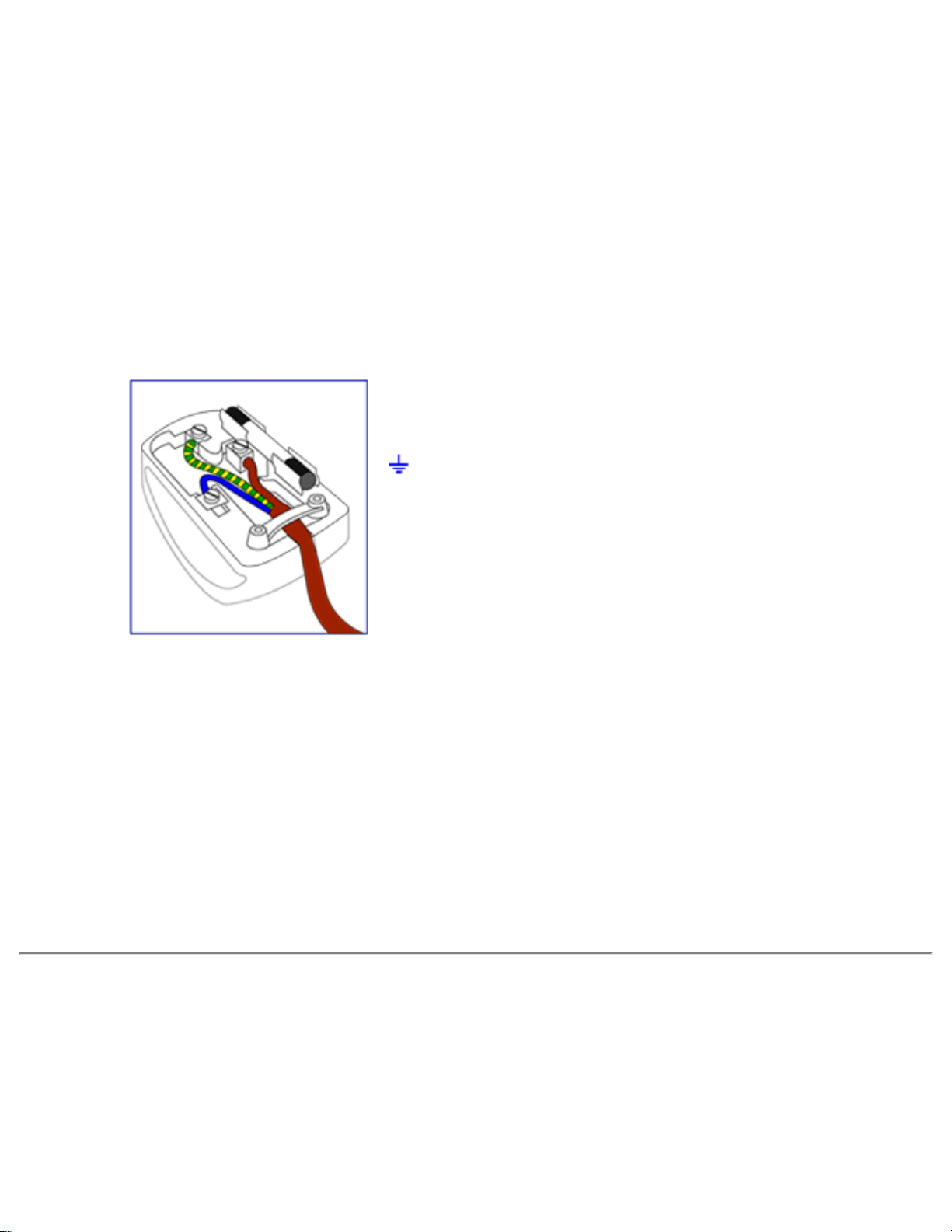
Regulatory Information
How to connect a plug
The wires in the mains lead are coloured in
accordance with the following code:
BLUE - "NEUTRAL" ("N")
BROWN - "LIVE" ("L")
GREEN & YELLOW - "EARTH" ("E")
1. The GREEN AND YELLOW wire must be
connected to the terminal in the plug which is
marked with the letter "E" or by the Earth symbol
or coloured GREEN or GREEN AND
YELLOW.
2. The BLUE wire must be connected to the
terminal which is marked with the letter "N" or
coloured BLACK.
3. The BROWN wire must be connected to the
terminal which marked with the letter "L" or
coloured RED.
Before replacing the plug cover, make certain
that the cord grip is clamped over the sheath of
the lead - not simply over the three wires.
RETURN TO TOP OF THE PAGE
Waste Electrical and Electronic Equipment-WEEE
Attention users in European Union private households
file:///D|/My%20Documents/dfu/BDL4221V/english/420wn6/SAFETY/REGS/REGULAT.HTM (10 of 11)2005-11-07 12:55:08 PM
Page 77

Regulatory Information
This marking on the product or on its packaging illustrates that, under European Directive
2002/96/EG governing used electrical and electronic appliances, this product may not be disposed of with
normal household waste. You are responsible for disposal of this equipment through a designated waste
electrical and electronic equipment collection. To determine the locations for dropping off such waste
electrical and electronic, contact your local government office, the waste disposal organization that serves
your household or the store at which you purchased the product.
RETURN TO TOP OF THE PAGE
file:///D|/My%20Documents/dfu/BDL4221V/english/420wn6/SAFETY/REGS/REGULAT.HTM (11 of 11)2005-11-07 12:55:08 PM
Page 78

Other Related Information
Other Related Information
Safety and Troubleshooting • FAQs • Troubleshooting • Regulatory Information • Information
for Users in the U. S. • Information for Users Outside the U.S
Information for Users in the U. S.
For units set at 115 V :
Use a UL Listed Cord Set consisting of a minimum 18 AWG, Type SVT or SJT three conductor cord
a maximum of 15-feet long and a parallel blade, grounding type attachment plug rated 15 A, 125 V.
For units set at 230 V:
Use a UL Listed Cord Set consisting of a minimum 18 AWG, Type SVT or SJT three conductor cord
a maximum of 15-feet long and a tandem blade, grounding type attachment plug rated 15 A, 250 V.
Information for Users outside the U.S.
For units set at 230 V:
Use a Cord Set consisting of a minimum 18 AWG cord and grounding type attachment plug rated
15 A, 250 V. The Cord Set should have the appropriate safety approvals for the country in which
the equipment will be installed and / or be marked HAR.
RETURN TO TOP OF THE PAGE
file:///D|/My%20Documents/dfu/BDL4221V/english/420wn6/SAFETY/saf_other.htm2005-11-07 12:55:08 PM
Page 79

Philips Pixel Defect Policy
Philips Pixel Defect Policy
Product Features • Technical Specifications • Resolution and Preset Modes • Automatic
Power Saving • Physical Specification • Pin Assignment • Product Views
Philips' LCD Panel Pixel Defect Policy
Philips strives to deliver the highest quality products. We use some of the industry's most advanced
manufacturing processes and practise stringent quality control. However, pixel or sub pixel defects
on the TFT LCD panels used in flat panel monitors are sometimes unavoidable. No manufacturer
can guarantee that all panels will be free from pixel defects, but Philips guarantees that any monitor
with an unacceptable number of defects will be repaired or replaced under warranty. This notice
explains the different types of pixel defects and defines acceptable defect levels for each type. In
order to qualify for repair or replacement under warranty, the number of pixel defects on a TFT LCD
panel must exceed these acceptable levels. For example, no more than 0.0004% of the sub pixels
on a 15" XGA monitor may be defective. Furthermore, Philips sets even higher quality standards for
certain types or combinations of pixel defects that are more noticeable than others. This policy is
valid worldwide.
Pixels and Sub pixels
A pixel, or picture element, is composed of three sub pixels in the primary colors of red, green and
blue. Many pixels together form an image. When all sub pixels of a pixel are lit, the three colored
subpixels together appear as a single white pixel. When all are dark, the three colored sub pixels
together appear as a single black pixel. Other combinations of lit and dark sub pixels appear as
single pixels of other colors.
file:///D|/My%20Documents/dfu/BDL4221V/english/420wn6/PRODUCT/PIXEL.HTM (1 of 4)2005-11-07 12:55:14 PM
Page 80

Philips Pixel Defect Policy
Types of Pixel Defects
Pixel and sub pixel defects appear on the screen in different ways. There are two categories of pixel
defects and several types of sub pixel defects within each category.
Bright Dot Defects Bright dot defects appear as pixels or sub pixels that are always lit or 'on'. That
is, a bright dot is a sub-pixel that stands out on the screen when the monitor displays a dark pattern.
There are the types of bright dot defects:
One lit red, green or blue
sub pixel
Two adjacent lit sub pixels:
- Red + Blue = Purple
- Red + Green = Yellow
- Green + Blue = Cyan (Light Blue)
Three adjacent lit sub pixels
(one white pixel)
A red or blue bright dot must be more than 50 percent brighter than neighboring dots
while a green bright dot is 30 percent brighter than neighboring dots.
Black Dot Defects Black dot defects appear as pixels or sub pixels that are always dark or 'off'. That
is, a dark dot is a sub-pixel that stands out on the screen when the monitor displays a light pattern.
These are the types of black dot defects:
file:///D|/My%20Documents/dfu/BDL4221V/english/420wn6/PRODUCT/PIXEL.HTM (2 of 4)2005-11-07 12:55:14 PM
Page 81

Philips Pixel Defect Policy
One dark sub pixel Two or three adjacent dark sub pixels
Proximity of Pixel Defects
Because pixel and sub pixels defects of the same type that are near to one another may be more
noticeable, Philips also specifies tolerances for the proximity of pixel defects.
Pixel Defect Tolerances
In order to qualify for repair or replacement due to pixel defects during the warranty period, a TFT
LCD panel in a Philips flat panel monitor must have pixel or sub pixel defects exceeding the
tolerances listed in the following tables.
BRIGHT DOT DEFECTS ACCEPTABLE LEVEL
MODEL
BDL4221V
1 lit sub pixel 0
2 adjacent lit sub pixels 0
3 adjacent lit sub pixels (one white pixel) 0
75% ~ 50% of Dot 0
50% ~ Less Dot (Weak Dot) Max 7
Distance between two bright dot defects* N/A
Total bright dot defects of all types 0
file:///D|/My%20Documents/dfu/BDL4221V/english/420wn6/PRODUCT/PIXEL.HTM (3 of 4)2005-11-07 12:55:14 PM
Page 82

Philips Pixel Defect Policy
Tiny bright dots less then 50% R/B, 30% G Max 4
* Bright Dot is defined as dots (sub-pixels) which appeared brightly in the screen when the LCM
displayed with whole pattern & Bright Dot's brightess is defined over 50% of the brightness against
around. (but, Green bright dot is over 30% of brightness against around)
* Here in Tiny Bright Dot is defined as "for Red and Blue" the bright area should be no longer than
1/2 sub-pixel and for green the bright area should be no larger than 1/3 sub-pixel.
BLACK DOT DEFECTS ACCEPTABLE LEVEL
MODEL
BDL4221V
1 dark sub pixel 5 or fewer
2 adjacent dark sub pixels 1 or fewer
3 adjacent dark sub pixels 0
Distance between two black dot defects* 15 mm or more
Total black dot defects of all types 5 or fewer
TOTAL DOT DEFECTS ACCEPTABLE LEVEL
MODEL
BDL4221V
Total bright or black dot defects of all types 5 or fewer
Note:
* 1 or 2 adjacent sub pixel defects = 1 dot defect
All Philips monitors are ISO13406-2 Compliant
RETURN TO TOP OF THE PAGE
file:///D|/My%20Documents/dfu/BDL4221V/english/420wn6/PRODUCT/PIXEL.HTM (4 of 4)2005-11-07 12:55:14 PM
Page 83

[
SERIAL INTERFACE
COMUNICATION PROTOCOL
&
RC CONTROL
Philips
NAME ]
2838 100 05424
140
01
Page 84

[
Contents
1. Introduction...........................................................................................................................4
1.1 Purpose.........................................................................................................................4
1.2 Scope............................................................................................................................4
1.3 Definitions, Abbreviations and Acronyms .....................................................................4
1.4 References....................................................................................................................4
2. Enabling The IR Remote Control..........................................................................................5
2.1 Monitor Address............................................................................................................5
2.2 Enabling and disabling the IR remote control(Reserved) .............................................5
2.3 Changing the monitor address(Reserved)....................................................................5
2.4 Notice(Reserved)..........................................................................................................5
3. Serial Interface Communication Protocol .............................................................................7
3.1 General specifications...................................................................................................7
3.1.1 Protocol definition .................................................................................................7
3.1.2 Communication characteristics.............................................................................7
3.1.3 RS232 pin assignment..........................................................................................7
3.1.4 RS232 settings......................................................................................................7
3.2 Data frame....................................................................................................................8
3.2.1 Poll sequence: frame format.................................................................................8
3.2.2 Acknowledge to poll sequence: frame format.......................................................8
3.2.3 General sequence: frame format ..........................................................................9
3.2.4 Acknowledge to general sequence: frame format.................................................9
3.3 Available Commands..................................................................................................10
3.3.1 Geometry Group .................................................................................................11
3.3.1.1 VIDEO MODE .................................................................................................11
3.3.1.2 PIP SIZE .........................................................................................................11
3.3.1.3 PIP POSITION ................................................................................................12
3.3.1.4 ZOOM Type ....................................................................................................12
3.3.1.5 ZOOM ID.........................................................................................................13
3.3.2 Miscellaneous Group ..........................................................................................13
3.3.2.1 OPERATION HOURS.....................................................................................13
3.3.2.2 STANDBY.......................................................................................................14
3.3.2.3 LIGHT SENSOR .............................................................................................14
3.3.2.4 FACTORY RESET..........................................................................................15
3.3.2.5 SLEEP TIMER ................................................................................................16
3.3.2.6 TV SYSTEM....................................................................................................16
3.3.2.7 CHANNEL SEARCH.......................................................................................17
3.3.2.8 REMOTE CONTROLLER ...............................................................................17
3.3.2.9 KEYPAD LOCK CONTROLLER .....................................................................17
3.3.3 Picture Group......................................................................................................18
3.3.3.1 LANGUAGE ....................................................................................................18
3.3.3.2 AUTO ADJUST ...............................................................................................19
3.3.3.3 COLOR SETTING...........................................................................................19
3.3.3.4 VIDEO COLOR ...............................................................................................19
3.3.3.5 INPUT SELECT ..............................................................................................20
Philips
NAME ]
2838 100 05424
140
02
Page 85

[
3.3.3.6 PIP VIDEO SOURCE......................................................................................21
3.3.3.7 CHANNEL SELECTION..................................................................................22
3.3.4 Audio Group........................................................................................................22
3.3.4.1 SMART SOUND..............................................................................................22
3.3.4.2 VOLUME.........................................................................................................23
3.3.4.3 MUTE..............................................................................................................23
Philips
NAME ]
2838 100 05424
140
03
Page 86

[
1. Introduction
1.1 Purpose
This document describes how to operate the BDS Monitor Series, using the IR remote
control unit (using standard Philips RC5 code) and the RS-232 Serial Communication
Interface. This document defines all the command and messages exchanged between
the master and the slave monitors for BDS. It also describes the ways to send or read
the commands or the messages.
1.2 Scope
This document is the reference for design, implementation and testing the RC and
RS232 communication module for Philips BDS project.
1.3 Definitions, Abbreviations and Acronyms
SICP stands for “Serial Interface Communication Protocol”.
1.4 References
Philips
NAME ]
2838 100 05424
140
04
Page 87

[
2. Enabling The IR Remote Control
2.1 Monitor Address
To allow individual control, a 3-digit address (decimal format) is assigned to each
monitor that can be modified by the user.
The default address set in the factory is 000.
2.2 Enabling and disabling the IR remote control(Reserved)
If the remote controller is disabled by the SICP command in section 3.3.2.9, the remote
controller doesn’t work since the monitor is powered on. It is possible to enable or
disable the remote control device on the addressed monitor by sending the following key
code:
<UP>1<UP> XXX Enable remote control on the addressed (XXX) monitor
<DN>0<DN> XXX Disable remote control on the addressed (XXX) monitor
Where <UP> and <DN> stand for the “UP” and “DOWN” cursor buttons on the IR remote
controller (see also Fig. 1
seconds, or the input sequence will be reset.
]). The input of two consecutive buttons cannot exceed 3
2.3 Changing the monitor address(Reserved)
It is possible to modify the monitor address by means of the following two commands:
<UP>9<UP> NNN Set a new address (NNN), also enabling the remote control
<DN>9<DN> NNN Set a new address (NNN), also disabling the remote control
The input of two consecutive buttons cannot exceed 3 seconds, or the input sequence
will be reset.
When using the above commands, please be sure that only the relevant monitor is
switched on, in order to avoid interference with the other ones.
2.4 Notice(Reserved)
If the panel is on stand-by, it wakes up after receiving one of the above commands. If not
used for more than 30 seconds (that counts since the last button input is received), the
IR interface is automatically disabled.
Philips
NAME ]
2838 100 05424
140
05
Page 88

[
Fig. 1 Remote controllers for BDS PAL and NTSC model on the left and right, respectively.
Philips
NAME ]
2838 100 05424
140
06
Page 89

[
3. Serial Interface Communication Protocol
3.1 General specifications
3.1.1 Protocol definition
Communication to the main monitor microprocessor is possible through the serial port,
which support a communication protocol dedicated to BDS only. The protocol is
specifically designed to allow data communication in half duplex multi-point
environments, but it can also be used for half duplex point-to-point RS-232
communication.
3.1.2 Communication characteristics
A half duplex communication is implemented starting from the concept of a master-slave
structure, where the monitor is supposed to be the slave.
The first action is always taken by the master, which can be either a built-in PC-based
video controller in a MASTER monitor or any external device (acting a server) interfaced
to the monitor. After sending a command or a request in the appropriate format (see
section 3.2), the master receives form the slave an acknowledgement, which tells the
transmitter whether the command is not valid (or not executable, anyway) or it is
accepted.
In case of a request, the requested information is sent back and it becomes the
acknowledgement by itself.
If the poll sequence has been sent, the acknowledgement tells the transmitter the
monitor status, i.e. whether it is ready or busy and other information.
3.1.3 RS232 pin assignment
There is a 9-pin male connector on the set for RS232 communication. The pin
assignment is as following table.
3.1.4 RS232 settings
This section describes the parameters used during the whole communication process.
Baud rate 57600 bps
Data bits 8 bits
Parity None
Stop bit 1
Flow Control None
Pin No. Function Description
1 GND Signal Ground
2 RxD Receive Data
3 TxD Transmit Data
4 NC Not Connected
5 GND Signal Ground
6 NC Not Connected
7 NC Not Connected
8 NC Not Connected
9 NC Not Connected
Philips
NAME ]
2838 100 05424
140
07
Page 90

[
3.2 Data frame
3.2.1 Poll sequence: frame format
The poll sequence must be transmitted before sending any command, to check whether
the monitor is ready to accept a command or it is busy.
The poll message in enclosed in a frame that has the following format:
<Start> <Address> <E> <Stop>
where:
<Start> = <Esc> <$>, i.e. ASCII characters [1Bh] and [24h].
<Address> = 3 ASCII characters each of which ranging from [30h] to [39h], which are
used as monitor address.
<E> = the ASCII character [45h].
<Stop> = <;>, i.e. the ASCII character [3Bh].
3.2.2 Acknowledge to poll sequence: frame format
Once the monitor has received the poll sequence, it returns the following message:
<Ack Flag> <Address> <Stauts> <Stop>
where:
<Ack Flag> = <Esc> <%>, i.e. ASCII characters [1Bh] and [25h].
<Address> = 3 ASCII characters each of which ranging from [30h] to [39h], which are
used as monitor address.
<Status> = 2 ASCII characters (ranging from [30h] to [39h], i.e. digits <0> to <9>,
and from [41h] to [46h]), i.e. letters <A> to <F>), representing the most
significant nibble (bit 7 to bit 4) and the least significant nibble (bit 3 to
bit 0) of the Status byte, respectively.
The meaning of the bits in the status byte is as follows:
Bit [7]: set to 0 (not used, reserved)
Bit [6]: set to 0 (not used, reserved)
Bit [5]: set to 0 (not used, reserved)
Bit [4]: set to 0 (not used, reserved)
Bit [3]: set to 0 (not used, reserved)
Bit [2]: Overheated 0 = Normal 1 = Overheated
Bit [1]: Standby 0 = Normal 1 = Standby
Bit [0]: Ready 0 = Not Ready 1 = Ready
<Stop> = <;>, i.e. the ASCII character [3Bh].
Philips
NAME ]
2838 100 05424
140
08
Page 91

[
Note: While Standby bit is set, the SICP engine accepts only STANDBY command in
miscellaneous group is accepted.
3.2.3 General sequence: frame format
A message can be sent to the monitor to execute a command or to ask for any
information; each message is enclosed in a frame, which consists of the following:
<Start> <Address> <Group> <Command> <Data1> <Data2> ... <DataN> <Stop>
where:
<Start> = <Esc> <$>, i.e. ASCII characters [1Bh] and [24h].
<Address> = 3 ASCII characters each of which ranging from [30h] to [39h], which are
used as monitor address.
<Group> = An ASCII character that identifies the command type selected among
the list below:
<G> [47h] = Geometry Group
<M> [4Dh] = Miscellaneous Group
<P> [50h] = Picture Group
<A> [41h] = Audio Group
<D> [44h] = Debug Group(Reserved)
<Command> = Two ASCII characters (ranging from [30h] to [39h], i.e. digits <0> to
<9>, and from [41h] to [5Ah]), i.e. letters <A> to <Z>), defining the
command.
<Data1> ... = Two ASCII characters (ranging from [30h] to [39h], i.e. digits <0> to
<9>, and from [41h] to [46h]), i.e. letters <A> to <F>), representing the
hex value of the data, or one ASCII characters when data are text
strings.
Write commands may become a request for the current value when
only <Data1> = <?> (i.e. [3Fh]) is sent.
<Stop> = <;>, i.e. the ASCII character [3Bh].
3.2.4 Acknowledge to general sequence: frame format
Once the monitor has received a general command sequence, it returns a message that
is one of the following when no data are expected as part of the answerback:
<Ack>
<Nack>
In case data are expected, then the message becomes:
Philips
NAME ]
2838 100 05424
140
09
Page 92
[
<Ack Flag> <Address> <Group> <Command> <Data1> <Data2>...<DataN> <Stop>
where:
<Ack> = The ASCII character [06h], to tell the transmitter that the command has
been acknowledged.
<Nack> = The ASCII characters [15h], to tell the transmitter that the command
has not been acknowledged, because the command itself is not valid
for any reason.
<Ack Flag> = <Esc> <%>, i.e. ASCII characters [1Bh] and [25h].
<Address> = 3 ASCII characters each of which ranging from [30h] to [39h], which are
used as monitor address.
<Group> = An ASCII character which identifies the command type, i.e. the same
identifier of the general command sequence that is being
acknowledged.
<Command> = Two ASCII characters (ranging from [30h] to [39h], i.e. digits <0> to
<9>, and from [41h] to [5Ah]), i.e. letters <A> to <Z>), defining the
command, i.e. the same identifier of the general command sequence
that is being acknowledged.
<Data1>... = Two ASCII characters (ranging from [30h] to [39h], i.e. digits <0> to
<9>, and from [41h] to [46h]), i.e. letters <A> to <F>), representing the
hex value of the data, or one ASCII characters when data are text
strings.
<Stop> = <;>, i.e. the ASCII character [3Bh].
3.3 Available Commands
Note:
1. Write commands may become a request for the current value when only <Data1>
= <?> (i.e. [3Fh]) is sent.
2. A character <X> means a “don’t care” value in this section.
3. There is an availability table attached to each command. See the following table.
(1) Each gray shaded cell in the table means the source is not available for the
corresponding model. “TV TUNER” input is not available in BASIC model for
example.
(2) A dot, ‘
model. For instance, the command is available in EXT input, PAL model.
Philips
NAME ]
•‘, means the command is available for the corresponding source and
Model
Source
PC ANALOG
PC DIGITAL
(DVI)
HDCP
PAL NTSC AP CHINA
140
10
2838 100 05424
Page 93
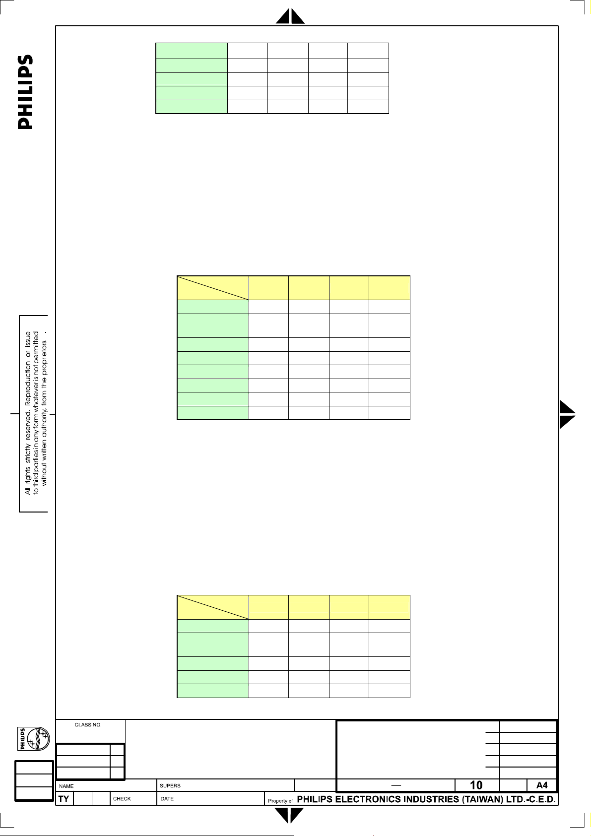
[
TV TUNER
COMPOSITE
S VIDEO
EXT
HDTV
3.3.1 Geometry Group
3.3.1.1 VIDEO MODE
Command: VM
Function: Set the format of the screen output for video inputs.
Data Range:
[00h] – WIDE SCREEN(STANDARD MODE)
[01h] – 4:3
[02h] – ZOOM 16:9 (FULL SCREEN)
[03h] – SUPER WIDE (NONLINEAR SCALING)
Source
PC ANALOG
PC DIGITAL
(DVI)
HDCP
TV TUNER
COMPOSITE
S VIDEO
EXT
HDTV
•
Model
PAL NTSC AP CHINA
• • • •
• • • •
• • • •
• • • •
• • • •
• • • •
3.3.1.2 PIP SIZE
Command: PS
Function: Control the PIP size.
Data Range:
[00h] – PIP OFF
[01h] – Small size
[02h] – Medium size
[03h] – Large size
[04h] – PBP size
Philips
NAME ]
Model
Source
PC ANALOG
PC DIGITAL
(DVI)
HDCP
TV TUNER
COMPOSITE
PAL NTSC AP CHINA
• • • •
• • • •
140
11
2838 100 05424
Page 94
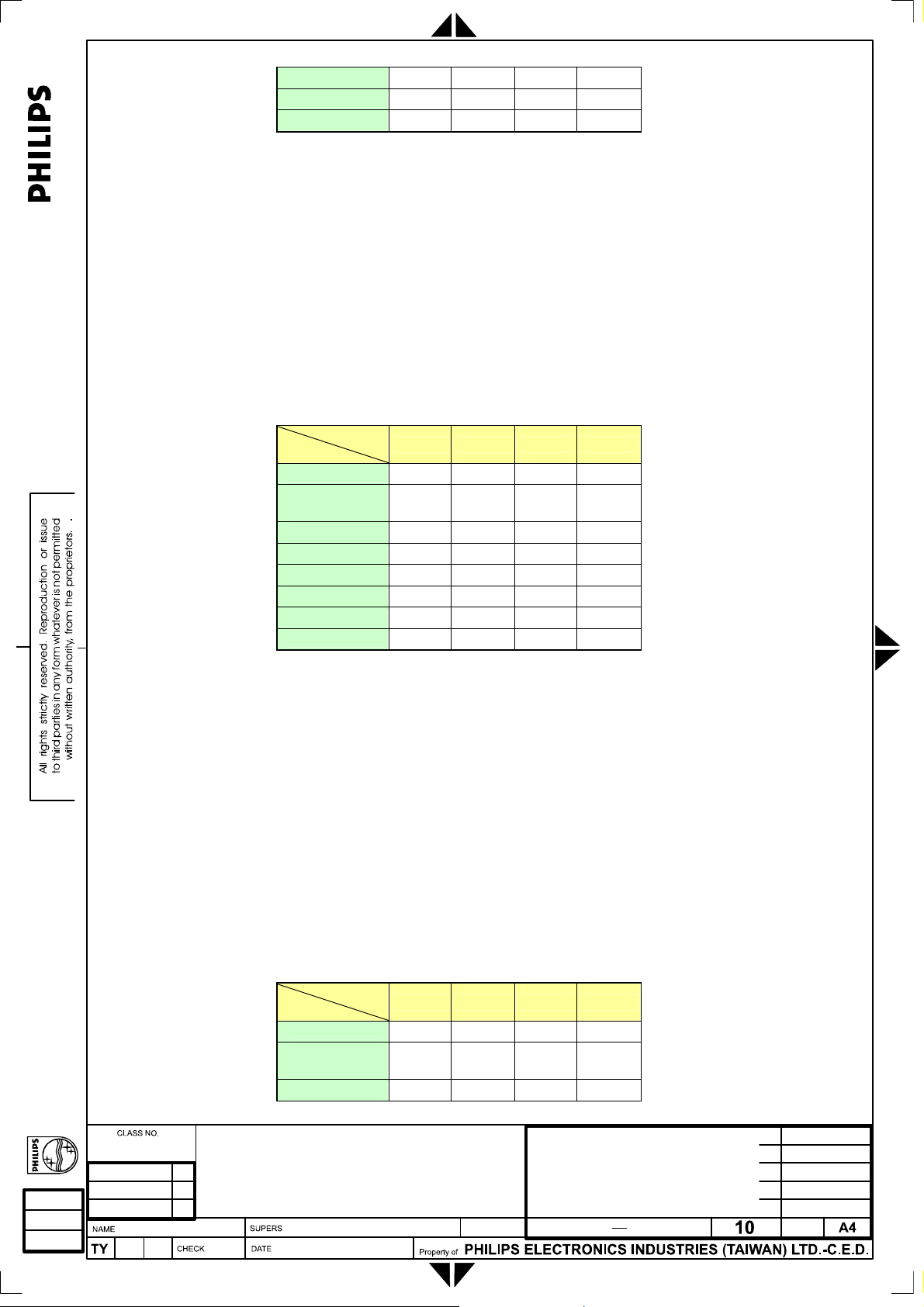
[
S VIDEO
EXT
HDTV
3.3.1.3 PIP POSITION
Command: PP
Function: Control the PIP position.
Data Range:
[00h] – Upper left corner
[01h] – Upper right corner
[02h] – Bottom right corner
[03h] – Bottom left corner
This command is only supported in PC Analog/Digital inputs and when the
PIP is not OFF.
Source
PC ANALOG
PC DIGITAL
(DVI)
HDCP
TV TUNER
COMPOSITE
S VIDEO
EXT
HDTV
Model
PAL NTSC AP CHINA
• • • •
• • • •
3.3.1.4 ZOOM Type
Command: ZT
Function: Select Zoom type.
Data Range:
[00h] – Zoom type 1x1(zoom off)
[01h] – Zoom type 4x4
[02h] – Zoom type 3x3
[03h] – Zoom type 2x2
[04h] – Zoom type 1x5
Source
PC ANALOG
PC DIGITAL
(DVI)
HDCP
Philips
NAME ]
Model
PAL NTSC AP CHINA
• • • •
• • • •
• • • •
140
12
2838 100 05424
Page 95
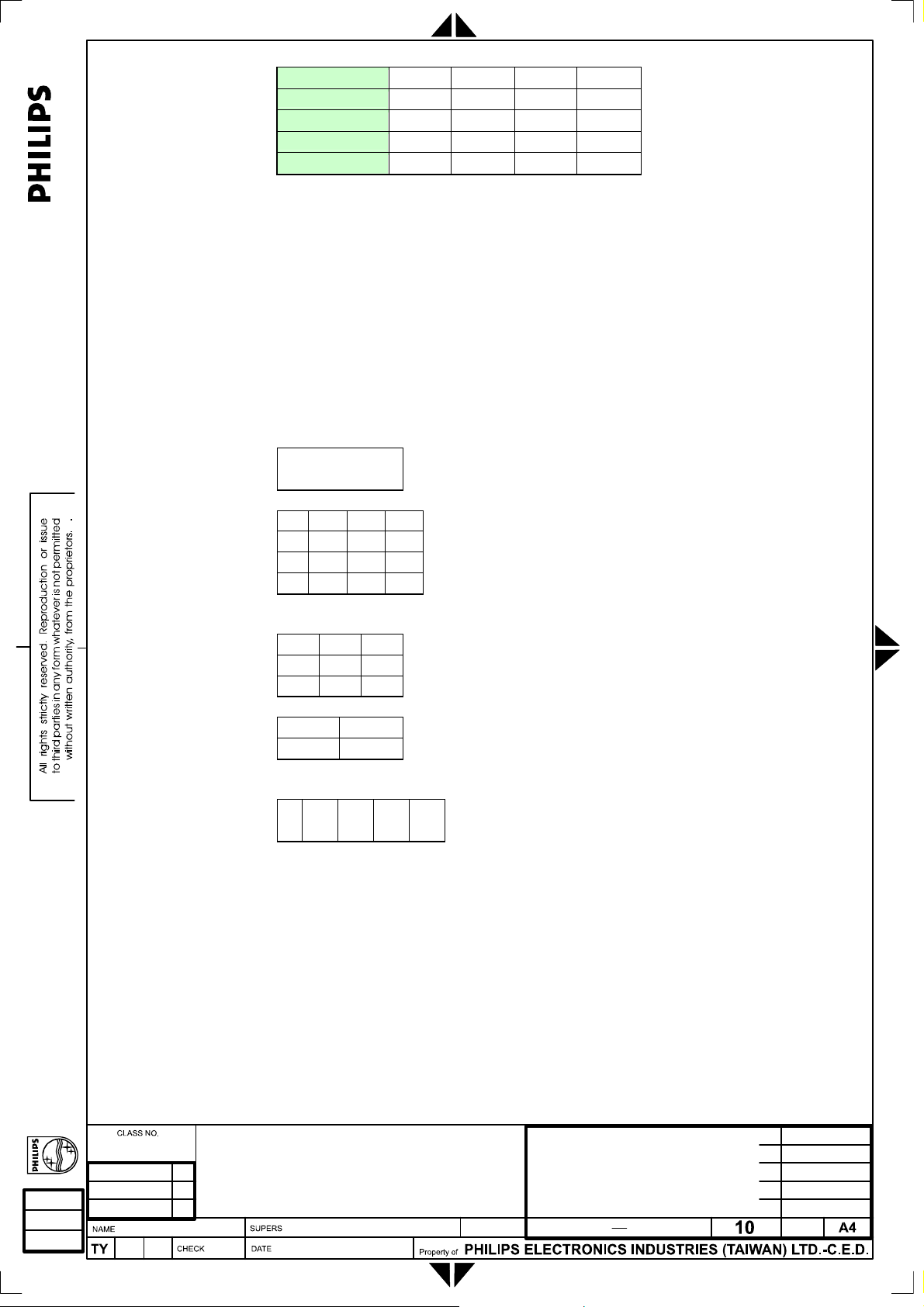
[
TV TUNER
COMPOSITE
S VIDEO
EXT
HDTV
• • • •
• • • •
• • • •
• • • •
• • • •
3.3.1.5 ZOOM ID
Command: ZD
Function: Select Zoom ID .
Data Range: It depend on zoom type.
[00h] : [00h] ----- Zoom type 1x1(Zoom off)
[00h] : [0Fh] ----- Zoom type 4x4
[00h] : [08h] ----- Zoom type 3x3
[00h] : [03h] ----- Zoom type 2x2
[00h] : [04h] ----- Zoom type 1x5
0
•0 •1 •2 •3
•4 •5 •6 •7
•8 •9 •A •B
•C •D •E •F
•0 •1 •2
•3 •4 •5
•6 •7 •8
•0 •1
•2 •3
•0 •1 •2 •3 •4
3.3.2 Miscellaneous Group
3.3.2.1 OPERATION HOURS Command: OH
Function: Operation hours of the target monitor.
Data Range:
[00000d] to [65535d] (5 digits)
This a “query only” command.
Philips
NAME ]
140
13
2838 100 05424
Page 96

[
3.3.2.2 STANDBY
Command: SB
Function: Standby ON/OFF.
Data Range:
[00h] – Standby OFF
[01h] – Standby ON
“Standby ON” means the set enters standby mode.
Query is not supported in this command.
Model
Source
PC ANALOG
PC DIGITAL
(DVI)
HDCP
TV TUNER
COMPOSITE
S VIDEO
EXT
HDTV
Model
Source
PC ANALOG
PC DIGITAL
(DVI)
HDCP
TV TUNER
COMPOSITE
S VIDEO
EXT
HDTV
PAL NTSC AP CHINA
PAL NTSC AP CHINA
• • • •
• • • •
• • • •
• • • •
• • • •
• • • •
3.3.2.3 LIGHT SENSOR
Command: LS
Function: Light sensor ON/OFF.
Data Range:
[00h] – Light Sensor OFF
[01h] – Light Sensor ON
Enabling this feature enables the automatically brightness control for more
comfortable viewing.
Model
Source
PC ANALOG
PC DIGITAL
(DVI)
PAL NTSC AP CHINA
• • • •
• • • •
Philips
NAME ]
2838 100 05424
140
14
Page 97
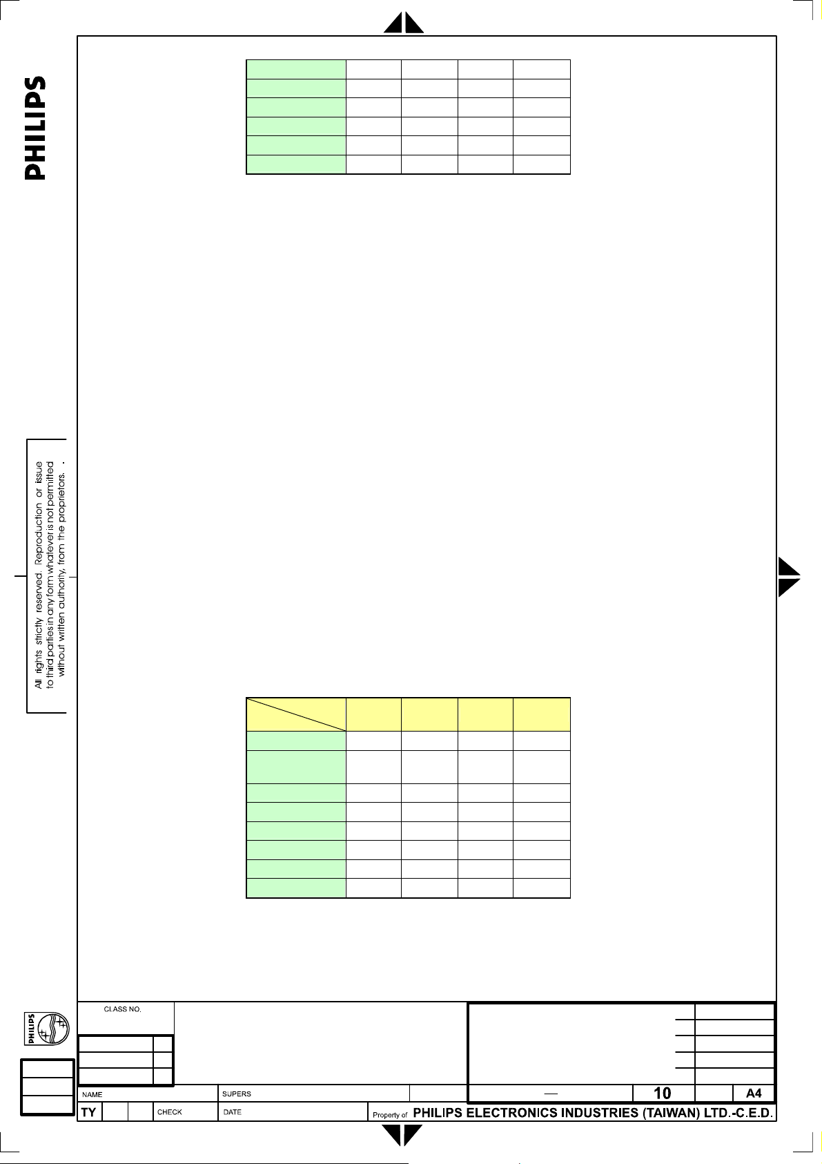
[
HDCP
TV TUNER
COMPOSITE
S VIDEO
EXT
HDTV
3.3.2.4 FACTORY RESET
Command: RE
Function: Reset system to default state.
Data Range:
The following values are applied only if PC analog/digital input is
selected.
[00h] – Position settings only
Recall all those settings of the current timing, including
This option has no effect in PC digital input.
[01h] – Color settings only
Reset color related settings including:
Set color temperature to “NORMAL Color”,
Set brightness and contrast level to 50%, and
[02h] – All settings
Recall all position and color related settings.
There is no data required for HDCP/Tuner/ CVBS/ S-video/EXT/HDTV
input. The reset function for these input sources sets the brightness/ color/
contrast/ sharpness to default values, tint to 50% level, video mode to
“16:9 / Normal Mode”, recalls the treble/ bass/ spatial effect values for the
current smart sound setting, and set the balance to the middle.
Query is not supported in this command.
Source
PC ANALOG
PC DIGITAL
(DVI)
HDCP
TV TUNER
COMPOSITE
S VIDEO
EXT
HDTV
• • • •
• • • •
• • • •
• • • •
• • • •
• • • •
horizontal/vertical position, phase and clock.
Model
PAL NTSC AP CHINA
• • • •
• • • •
• • • •
• • • •
• • • •
• • • •
• • • •
• • • •
Philips
NAME ]
2838 100 05424
140
15
Page 98
[
3.3.2.5 SLEEP TIMER
Command: SL
Function: Set the sleep timer for all video inputs.
Data Range:
[00h] – OFF
[01h] – 15 minutes
[02h] – 30 minutes
[03h] – 45 minutes
[04h] – 60 minutes
[05h] – 90 minutes
[06h] – 120 minutes
[07h] – 180 minutes
[08h] – 240 minutes
Query is not applicable in this command.
This command is not supported in PC Analog/Digital inputs.
Source
PC ANALOG
PC DIGITAL
(DVI)
HDCP
TV TUNER
COMPOSITE
S VIDEO
EXT
HDTV
Model
PAL NTSC AP CHINA
• • • •
• • • •
• • • •
• • • •
• • • •
• • • •
3.3.2.6 TV SYSTEM
Command: TS
Function: Select TV system used for tuner input.
Data Range:
[00h] – EUROPE
[01h] – FRANCE L
This feature is only supported in PAL model.
Query is not applicable in this command.
Source
PC ANALOG
PC DIGITAL
(DVI)
HDCP
TV TUNER
COMPOSITE
S VIDEO
EXT
HDTV
Model
PAL NTSC AP CHINA
•
Philips
NAME ]
2838 100 05424
140
16
Page 99

[
3.3.2.7 CHANNEL SEARCH
Command: SE
Function: Automatically search all existing channels.
Data Range:
No data is required for this command.
Query is not applicable in this command.
This command is only supported in TV models.
Source
PC ANALOG
PC DIGITAL
(DVI)
HDCP
TV TUNER
COMPOSITE
S VIDEO
EXT
HDTV
Model
PAL NTSC AP CHINA
• • • •
3.3.2.8 REMOTE CONTROLLER
Command: RC
Function: Enable/Disable remote controller.
Data Range:
[00h] – Disable.
[01h] – Enable.
Once the remote controller is disabled by this command, the controller can
be reactivated for a period of time by the procedure described in section
2.2.
Query is not supported in this command.
Model
Source
PC ANALOG
PC DIGITAL
(DVI)
HDCP
TV TUNER
COMPOSITE
S VIDEO
EXT
HDTV
PAL NTSC AP CHINA
• • • •
• • • •
• • • •
• • • •
• • • •
• • • •
• • • •
• • • •
3.3.2.9 KEYPAD LOCK CONTROLLER
Command: KL
Function: Enable/Disable keypad controller.
Data Range:
Philips
NAME ]
2838 100 05424
140
17
Page 100

[
[00h] – Enable keypad function.
[01h] – Disable keypad function.
Once the keypad controller is disabled by this command, the controller
can be reactivated for a period of time from wake up or power on
Query is not supported in this command.
Model
Source
PC ANALOG
PC DIGITAL
(DVI)
HDCP
TV TUNER
COMPOSITE
S VIDEO
EXT
HDTV
PAL NTSC AP CHINA
• • • •
• • • •
• • • •
• • • •
• • • •
• • • •
• • • •
• • • •
3.3.3 Picture Group
3.3.3.1 LANGUAGE
Command: LA
Function: Select the OSD language.
Data Range:
[00h] – English
[01h] – Spanish
[02h] – French
[03h] – Deutsch
[04h] – Italian
[05h] – Simplified Chinese
Simplified Chinese is only supported in AP and CHINA model.
Source
PC ANALOG
PC DIGITAL
(DVI)
HDCP
TV TUNER
COMPOSITE
S VIDEO
EXT
HDTV
Model
PAL NTSC AP CHINA
• • • •
• • • •
• • • •
• • • •
• • • •
• • • •
• • • •
• • • •
Philips
NAME ]
2838 100 05424
140
18
 Loading...