

Page 1

32 inch WXGA TFT LCD Monitor/TV
Service
Chassis: BDS
Service
Service
BDL3221V/00
BDL3221V/27
BDL3221VS/00
320WN6QS/93
320WN6QS/97
TABLE OF CONTENTS
Description Page
Important Safety Notice---- ------------------------------ 2
Technical Data----------------------------------------------3
Instalation&On Screen Display---------------------4~12
Circuit Description ----13
Lock/unlock,Aging,Factory mode ---------------------14
Philips Pixel Defect Policy 15
Mechanical Instructions----------------------------16~17
Color adjustment -----------------------------------------18
Warning Message ----------------------------------------19
Troubleshooting--------------------------------------20~21
Electrical instruction --------------------------------22~26
DDC Instructions-------------------------------------27~33
DDC DATA --------------------------------------------34~35
ISP Instructions --------------------------------------36~37
Failure mode of panel------------------------------------38
------------------------------------
------------------------------
Horizontal frequencies
30-63kHz
Description Page
Wiring&Block Diagram-----------------------------39~40
Scaler Diagram&C.B.A. ---------------------------41~58
Power Diagram&C.B.A. ---------------------------59~61
Control Diagram&C.B.A.-------------------------------62
DSUB Diagram&C.B.A.---------------------------------63
IR Diagram & C.B.A. ------------------------------------64
Exploded View -------------------------------------------65
Spare& parts list-----------------66~71
General product specification ------------------72~103
Repair tips ----------------------------------------104~105
Repair Flow chart--------------------------------106~107
Different parts list--------------------------------------108
Updated for 320WN6QS------------------------------109
Safety Test Requirments -----------------------------110
Revision List --------------------------------------------111
Recommended
SAFETY NOTICE
ANY PERSON ATTEMPTING TO SERVICE THIS CHASSIS MUST FAMILIARIZE HIMSELF WITH THE CHASSIS
AND BE AWARE OF THE NECESSARY SAFETY PRECAUTIONS TO BE USED WHEN SERVICING ELECTRONIC
EQUIPMENT CONTAINING HIGH VOLTAGES.
CAUTION: USE A SEPARATE ISOLATION TRANSFORMER FOR THIS UNIT WHEN SERVICING.
REFER TO BACK COVER FOR IMPORTANT SAFETY GUIDELINES
Published by BCU Monitors Printed in Suzhou Copyright reserved Subject to modification K Aug. 05 2005
GB
3138 106 10486
Page 2

2
BDL3221 LCD/TV
Go to cover page
Proper service and repair is important to the safe,
reliable operation of all Philips Consumer Electronics
Company** Equipment. The service procedures
recommended by Philips and described in this service
manual are effective methods of performing service
operations. Some of these service operations require
the use of tools specially designed for the purpose. The
special tools should be used when and as
recommended.
It is important to note that this manual contains various
CAUTIONS and NOTICES which should be carefully
read in order to minimize the risk of personal injury to
service personnel. The possibility exists that improper
service methods may damage the equipment. It is also
important to understand that these CAUTIONS and
NOTICES ARE NOT EXHAUSTIVE. Philips could not
possibly know, evaluate and advise the service trade of
all conceivable ways in which service might be done or
of the possible hazardous consequences of each way.
Consequently, Philips has not undertaken any such
broad evaluation. Accordingly, a servicer who uses a
service procedure or tool which is not recommended by
Philips must first satisfy himself thoroughly that neither
his safety nor the safe operation of the equipment will
be jeopardized by the service method selected.
* * Hereafter throughout this manual, Philips Consumer
Electronics Company will be referred to as Philips.
WARNING
Critical components having special safety
characteristics are identified with a by the Ref. No.
in the parts list and enclosed within a broken line*
(where several critical components are grouped in one
area) along with the safety symbol on the
schematics or exploded views.
Important Safety Notice
!
!
Take care during handling the LCD module with
backlight unit
- Must mount the module using mounting holes
arranged in four corners.
- Do not press on the panel, edge of the frame
strongly or electric shock as this will result in damage
to the screen.
- Do not scratch or press on the panel with any sharp
objects, such as pencil or pen as this may result in
damage to the panel.
- Protect the module from the ESD as it may damage
the electronic circuit (C-MOS).
- Make certain that treatment person s body are
grounded through wrist band.
Use of substitute replacement parts which do not have
the same specified safety characteristics may create
shock, fire, or other hazards.
Under no circumstances should the original design be
modified or altered without written permission from
Philips. Philips assumes no liability, express or implied,
arising out of any unauthorized modification of design.
Servicer assumes all liability.
* Broken Line
Page 3

Technical Data
BDL3221 LCD/TV
Go to cover page
3
LCD panel
Type NO : LC320W01 A6K3 (Supplier LPL)
Display area(mm) : 697.685mm x 392.256mm
Number of Pixels : 1366(H) x 768(V)
Pitch ( mm ) : 0.170mm(H) x 0.510mum(V)
Color pixel arrangement : RGB vertical stripe
Display operating mode : Normally black
Color depth : 16,7M colors ( 8 bits)
Brightness (cd/m^2) : 500(Center 1 points, Ty p.)
Viewing angle(CR>10) : Viewing angle free(R/L 178(Typ.),U/D
178(Typ.))
Surface treatment : Hard coating(3H),Anti-glare treatment
of the front polarize
Electrical interface : LVDS
Response Time (ms, Typ) : TrR:8,TrD:10(Gray to Gray)
Contrastratio :Typical1000:1withAI
Outline Dimension : 760 mm(H) x 450 mm(V) x 48(D)
mm (Typ.)
Module weight (g) : 7200g(Typ.)
Backlight : 20 EEFL
Power supply
AC-input : 90V ~ 264VAC,50/60±2Hz
Power consumption : 100W/Typ(at PC mode),
130W/Typ(at TV mode).
Power cord length : 1.8M
Power cord type : European type and UK type
Power indicator : LED (On: Blue ,Sleeping
mode: A mber )
Auto power saving : < 5W
Horizontal scan : 30 ~ 63KHz
Vertical scan : 50 ~ 75 Hz
Power Management Definition
VESA Mode Video H-sync V-sync Power Used LE D color
Active On Yes Yes 100 W (typ.) Blue
Sleep Off No No <5W Amber
Switch Off Off - - <3W Off
Pin Assignment
Pin No. Description
1
2
3
4
5
6
7
8
9
10
11
12
13
14
15
16
17
18
19
20
21
22
23
24
T.M.D.S. data2-
T.M.D.S. data2+
T.M.D.S. data2 shield
No Connect
No Connect
DDC clock
DDC data
No Connect
T.M.D.S. data1-
T.M.D.S. data1+
T.M.D.S. data1 shield
No Connect
No Connect
+5V Power
Ground (for +5V) - Cable detect
Hot plug detect
T.M.D.S. data0-
T.M.D.S. data0+
T.M.D.S. data0 shield
No Connect
No Connect
T.M.D.S clock shield
T.M.D.S. clock+
T.M.D.S. clock-
Environmental conditions
Operating
- Temperature : 0 to 40
- Humidity : 10 to 90%
- Altitude : 0-12,000 feet
- Air pressure : 645 mBAR
- (guaranteed optical performance) : 5 to 35
- (guaranteed functional performance) : 5 to 40
Storage
- Temperature : -20 to 50
- Humidity : 10- 90% (non-condensing )
- Air pressure : 600-1100 mBAR
Note: recommend at 0 to 35°C, Humidity less than 60 %
Shipping
- Temperature :( -20 to 60
- Humidity : 5- 90% (non-condensing )
- Altitude : 0-40000 feet ( non operating )
Air pressure : 188-1100 Mbar
)
Pin No.
2
3
4
5
6
7
8
Assignment
Red video input
1
Green video input
Blue video input
GND
Cable detect
Red video GND
Green video GND
Blue video GND
Input DVI-D connector pin
Pin No.
9
10
11
12
13
14
15
Assignment
DDC +5V
GND
GND
Serial data line (SDA)
H-sync
V-sync
Data clock line (SCL)
Page 4

4
BDL3221 LCD/TV
Go to cover page
Installation
Installing your LCD Monitor/TV
Side View (Left)
1 INPUT Selecting input source
2 Increase or decrease the channel number or
moving up or down to highlight the function in OSD
3 Increase or decrease the level of audio volume or
moving left or right to highlight the sub-menu in the
selected function of OSD
4 MENU Open the OSD or confirm the selected function
5 DC power switch On/Off
Side View (Right)
1 AC in AC power in
2 Speakers output External speakers output
3 D-Sub output PC analog D-Sub input
4 DVI-D input PC digital input
5 D-Sub input PC analog D-Sub input
6 RS232 input RS232 network connection
Input
7 RS232 output RS232 network connection
output for the use of loop
through function
8 PC audio PC stereo audio input
9 Audio input for component signal Audio (left and right) input for
component signal input
10 Component input Component (YPbPr ) signal
input
11 Composite output Composite (CVBS) output for
the use of loop through
function
12 Audio output for composite output Audio (left and right) out put
for compo site signal out put.
13 External / EURO-AV SCART connection (for the
use of European model only)
14 Kensington lock Kensington lock
Accessory Pack
Unpack all the parts
Item Description
1 Audio input for composite input Audio (left and right) in put for
compo site signal in put.
2 Composite input Composite (CVBS) signal input
3 S-Video input S-Video signal input
4 Earphone output Earphone output
5 TV tuner TV tuner input (available in TV
version only)
Rear View
Power cable
Remote control & batteries
DVI-D cable
VGA signal cable
E-DFU pack
Accessories below are available for TV model only
Item Description
Base
Screw pack
2x10 W Detachable Speakers
Page 5

Installation
BDL3221 LCD/TV
Go to cover page
5
Setting up and connecting your monitor/TV
- Connecting the monitor/TV
Connect the cables to the rear of your monitor/TV according to
·
the numbers:
TV model
- Connect to PC
Connect the cables to the back of your computer by following step
·
1~5.
If your monitor displays the computer image the installation has been
·
completed successfully.
If installation was not successful, see the Troubleshooting section.
·
For installation of the monitor driver for Microsoft Windows , see the
·
Monitor Driver Installation section (Getting Started).
R
· Connect to DVD/VCR /VCD through composite video (CVBS)
· Connect to DVD/VCR /VCD through component video (YPbPr)
Connecting to Cable TV
Antenna
- Connect to DVD/VCD/VCR
Connect to DVD/VCR/VCD through S-VIDEO
Connect to DVD/VCR/VCD through S-VIDEO·
· Connect to DVD/VCR /VCD through SCART (for Europe only)
Progressive video and HDTV connections for digital high-definition
picture
Page 6

6
BDL3221 LCD/TV
On Screen Display
Go to cover page
On Screen Display Controls
An overall view of the On-Screen Display (OSD) structure is shown
below. You can use it as a reference for further adjusting your
Monitor/TV.
There are two different modes of OSD available for different models:
PC Mode
·
TV Mode
·
Main menu
There is a slight difference between PC mode and TV mode: Setup
selection is available in TV mode only.
Page 7

On Screen Display
BDL3221 LCD/TV
Go to cover page
7
Page 8

8
BDL3221 LCD/TV
Go to cover page
On Screen Display
Page 9

On Screen Display
BDL3221 LCD/TV
Go to cover page
9
Page 10

10
BDL3221 LCD/TV
Go to cover page
On Screen Display
Page 11

On Screen Display
BDL3221 LCD/TV
Go to cover page
11
Page 12

12
BDL3221 LCD/TV
Go to cover page
On Screen Display
Page 13

Circuit Description
This LCD TV monitor use BDS platform for the video and audio processing.
It can support PC analog, digital signal and TV signal.
It support PIP function that is TV picture on PC graphic or TV picture on DVI (support HDCP).
It's output resolution is up to 1366X768 75Hz for WXGA panel.
It can support DVI HDCP digital signal input and also support TV (RF) , CVBS/ RG B signal ( from
SCART1 I/O) , YPbPr ( from Cinch I/O for SDTV and HDTV) , CVBS/YC ( Audio shared ) , It has one
headphone output.
The Y Pb Pr signal input (from Cinch I/O) support 480I, 480P, 720P, 1080i 60Hz and 576I,
576P, 720P, 1080I 50Hz HDTV input.
It also have PVR output function , support and monitor all the CVBS signal output with L/R sound.
This LCD monitor TV use MST5151A as Scaler engine, which has embedded Analog D-sub, digital DVI(HDMI) decoder,
scaling input signal for panel, OSD and advanced 3D de-interlace. The DDR SDRAM is used to accomplish video frame
rate conversion and PIP function.
The external CPU is used for back light control, RC receiver, keypad input, I/O switch control , IIC
communication and TV tuning control, MSP3450G sound decoder control, SAA7119 video decoder
control , Columbus IC ( 3D -comb filter ) control , and Audio AMP TPA3008D2 control.
Video decoder SAA7119 is used for TV video processing and convert it with CCIR 656/8bits digital format
and send to Columbus IC for 3D comb filter processing and noise reduction processing , after that then send
to Scaler for de-interlace process.
BDL3221 LCD/TV
13
Go to cover page
Columbus IC is a combination of Enhanced 2D / 3D Comb filter for both PAL and NTSC , and a Spatial /
Temporal noise reduction system for both colour and luminance signals .
One audio decoder MSP3450G is used for TV sound processing, and output to Class D audio amplifier
TPA3008D (2 X10W) audio output. This audio decoder is a global sound decoder for Nafta AP, China and European market.
In NAFTA model CC,V-chip data is decoded in SAA5264PS/M3/1437 and the display the CC information via
mixed at SAA7119 with the input signal.
The V-Chip is decode by SAA5264PS/M3/1437 and control via the MCU.
In Europe model "Teletext display". Data decode is done by SAA5264PS/M3/1437, output RGB/FB is to
video decoder input for text overlapping.
Page 14
14
BDL3221 LCD/TV
Go to cover page
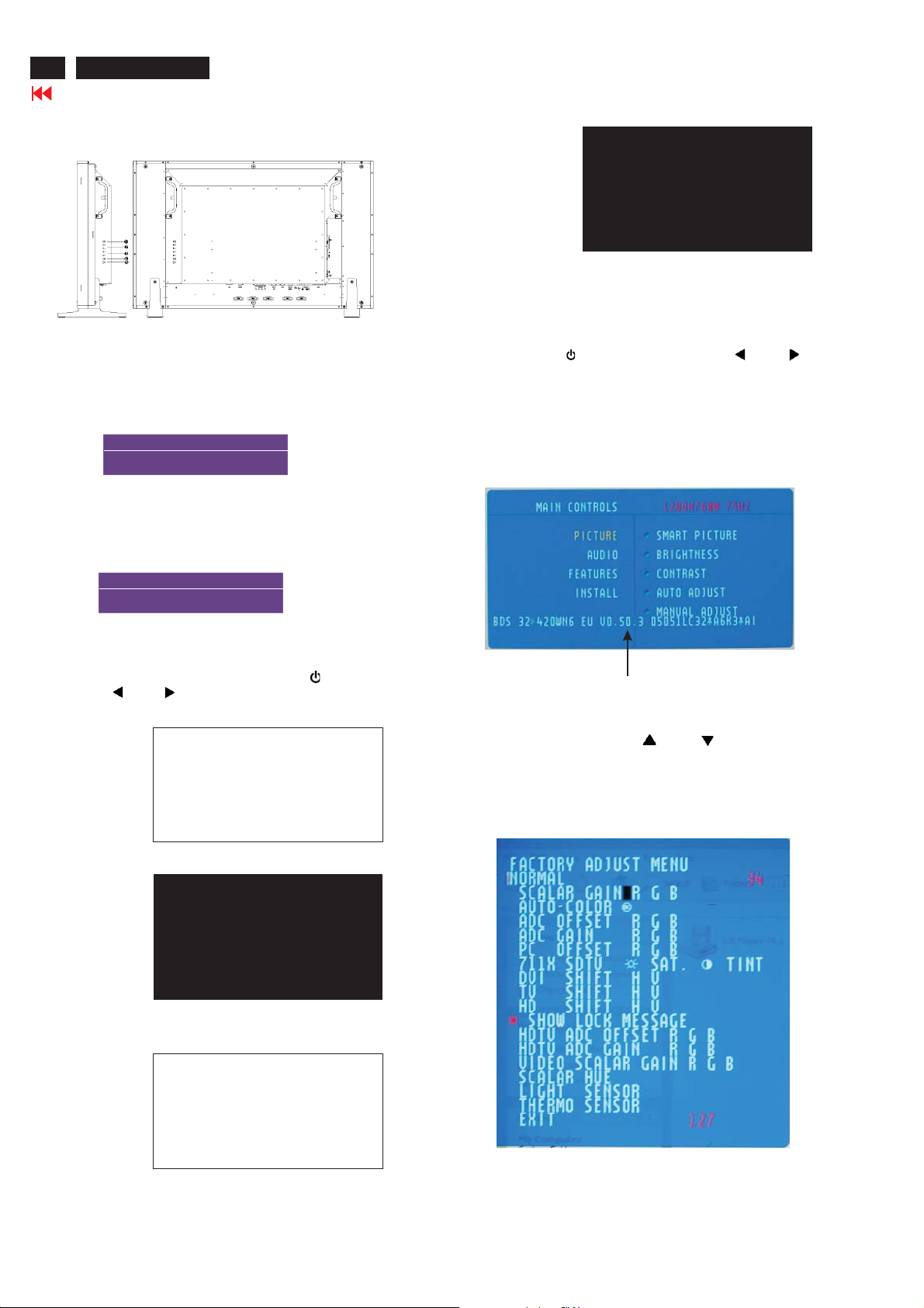
Lock/Unlock,Aging,Factory Mode
Side View (Left)
To Lock/Unlock OSD FUNCTION(User Mode)
The OSD function can be locked by pressing"MENU"button(1) for
more than 15 seconds, the screen shows following windows for 3
seconds.Everytime when you press"MENU" button, this message
appears on the screen automatically.
ATTENTION
OSD MAIN MENU LOCKED
Unlock OSD function
Unlocked OSD function can be released by pressing "MENU"
button for more than 15 seconds again.
ATTENTION
OSD MAIN MENU UNLOCKED
After 50 seconds,
bring up:
----------
---------repeatly
Connect Signal cable again=> go back to normal display
Access Factory Mode
1). Turn off monitor.
2).
Press power " " button.Then quickly push " " and " ",and
hold this two buttons , then the screen comes out "Waiting For
Automatic Adjustment ",then the screen will be black for one
second untill comes out "Windows screen"] => then release this
two buttons.
3). Press "MENU" button, wait until the OSD menu with
Characters "BDS 32*420WN6 EU V0.50.3 05051LC32*A
6K3*A1" (below OSD menu) come on the Screen of the
monitor.
Access Aging Mode
Step1:D
Step 2 :
quickly push " "and " ",and hold this two buttons
out " AGING screen"] => then release all buttons.
Bring up:
After 50 seconds,
bring up:
isconnect Interface Cable between Monitor and PC.
Turn off LCD monitor.Then press power " " button.Then
AGING...
AGING...
After 5 seconds,
bring up:
untill comes
Factory Mode indicator
Factory Menu
Cursor can move on gray color area
Hot key function: by pressing " " and " " key
Simultaneously at User Mode (or Factory Mode)
(PS: The OffsetRGBfunction can be used on reduce or eliminate
snowy noise on the background when the resolution of video signal
is 1280*768 vertical 75Hz. Slightly increase or decrease the value
until snowy noise completely disappear.
AGING...
Page 15

Philips Pixel Defect Policy
BDL3221 LCD/TV
Go to cover page
15
Philips' Flat Panel Monitors Pixel Defect Policy
Philips strives to deliver the highest quality products. We
use some of the industry's most advanced manufacturing
processes and practice stringent quality control. However,
pixel or sub pixel defects on the TFT LCD panels used in
flat panel monitors are sometimes unavoidable. No
manufacturer can guarantee that all panels will be free
from pixel defects, but Philips guarantees that any monitor
with an unacceptable number of defects will be repaired or
replaced under warranty. This notice explains the different
types of pixel defects and defines acceptable defect levels
for each type. In order to qualify for repair or replacement
under warranty, the number of pixel defects on a TFT LCD
panel must exceed these acceptable levels. For example,
no more than 0.0004% of the sub pixels on a 15" XGA
monitor may be defective. Furthermore, Philips sets even
higher quality standards for certain types or combinations
of pixel defects that are more noticeable than others. This
policy is valid worldwide.
Black Dot Defects Black dot defects appear as pixels or sub
pixels that are always dark or 'off'. These are the types of black
dot defects:
One dark sub pixel Two or three adjacent dark sub pixels
Proximity of Pixel Defects
Because pixel and sub pixels defects of the same type that are
near to one another may be more noticeable, Philips also specifies
tolerances for the proximity of pixel defects.
Pixel Defect Tolerances
In order to qualify for repair or replacement due to pixel defects
during the warranty period, a TFT LCD panel in a Philips flat panel
monitor must have pixel or sub pixel defects exceeding the
tolerances listed in the following tables.
Pixels and Sub pixels
A pixel, or picture element, is composed of three sub pixels
in the primary colors of red, green and blue. Many pixels
together form an image. When all sub pixels of a pixel are lit,
the three colored sub pixels together appear as a single
white pixel. When all are dark, the three colored sub pixels
together appear as a single black pixel. Other combinations
of lit and dark sub pixels appear as single pixels of other
colors.
Types of Pixel Defects
Pixel and sub pixel defects appear on the screen in different
ways. There are two categories of pixel defects and several
types of sub pixel defects within each category. Bright dot
defects appear as pixels or sub pixels that are always lit or
'on'. These are the types of bright dot defects:
One lit red,
green or
blue sub pixel
Two adjacent lit
sub pixels:
- Red+ Blue =Purple
- Red+ Green =Yellow
- Green+ Blue =Cyan
(Light Blue)
Three adjacent lit
sub pixels
(one white pixel)
* Bright Dot is defined as dots (sub-pixels) which appeared brightly in
the screen when the LCM displayed with whole pattern & Bright Dot's
brightess is defined over 50% of the brightness against around. (but,
Green bright dot is over 30% of brightness against around)
* Here in Tiny Bright Dot is defined as "for Red and Blue" the bright
area should be no longer than 1/2 sub-pixel and for green the bright
area should be no larger than 1/3 sub-pixel.
Note:
* 1 or 2 adjacent sub pixel defects = 1 dot defect
All Philips monitors are ISO13406-2 Compliant
Page 16

16
BDL3221 LCD/TV
Go to cover page
Mechanical Instruction
Front view
Back view
Step 1. Remove the tands.
sound boxs and s
Step 2: Remove the Back Cover Assy
a. Unscrew 20 screws as shown in Fig.6.
b. Unscrew 8 screws as shown in Fig.7.
c. Unscrew 9 screws as shown in Fig.8.
d. Remove the and BACK COVER ASSY in Fig.9.
Fig.1
Fig.6
Fig.2
Fig.7
a. Remove the sound boxs.
Unscrew the 4 screws as Fig.3
b. Remove the stands.
Unscrew the 6 screws as Fig.4 and Fig.5 .
Fig.8
Fig.3
Step 3. Remove the Scaler ,IR and Power board.
a. Unscrew the 12 screws and disconnect the 9 cables as Fig.9
and Fig.10.
b. Remove the Scaler ,IR and Power board as Fig. 11.
Fig.4
Fig.9
Fig.5
Fig.10
Page 17

Step 4. Remove the LCD panel.
Mechanical Instruction
BDL3221 LCD/TV
Go to cover page
17
a. Unscrew
b. Remove the as Fig.12.
c. Remove FRONT BEZEL ASSY(B) as Fig.13.
LCD Panel
1050 823827717361 LCD LC320W01-A6K1.
the 4 screws and disconnect the 2 cables as Fig. 11.
BOTTOM MAIN FRAME
Fig. 11
Fig. 12
Fig. 13
In warranty, it is not allowed to disassembly the LCD panel, even the
backlight unit defect.
Out of warranty, the replacment of backlight unit is a correct way
when the defect is cused by backlight (CCFL,Lamp).
Page 18

18
BDL3221 LCD/TV
Go to cover page
Color Adjustment
Alignment procedure
1. Turn on the LCD monitor.
2.Turn on the Timing/pattern generator. See Fig.1
3. Preset LCD color Analyzer CA-110
-Remove the lens protective cover of probe CA-A30.
-Set measuring/viewing selector to measuring position for reset
analyzer.(zero calibration) as Fig.2
- Turn on the color analyzer (CA-110)
-Press 0-CAL button to starting reset analyzer.
Cover (black)Cover (black)
Measurement viewing selectorMeasurement viewing selector
Fig. 2
Fig. 1
Fig. 2
4. Access Factory Mode
1). Turn off monitor.
2).
Press power " " button.Then quickly push " " and " ",and
hold this two buttons , then the screen comes out "Waiting For
Automatic Adjustment ",then the screen will be black for one
second untill comes out "Windows screen"] => then release this
two buttons.
3). Press "MENU" button, wait until the OSD menu with
Characters "BDS 32*420WN6 EU V0.50.3 05051LC32*A
6K3*A1" (below OSD menu) come on the Screen of the
monitor.
Clear imageClear image
Measurement/viewing selectorMeasurement/viewing selector
Fig.5
5.Display
Press " " or " " button to select . Change the value
by " " or " " key until the X,Y co-ordinates as below
5.1 Auto color adjustment (B)
Apply a 1360x768/60Hz signal with 32-gray levels pattern, Set
smart picture at "Normal" , and Brightness to 50% and Contrast to
50%. Set AUTO-COLOR function for auto ADC offset and gain
setup. Adjust the R. G. B offset, and gain to calibrate the color
smoothly and 32-gray level distinguishable. Check all factory presetting modes.
5.2 Adjustment of WHITE-D (B)
Apply a 1360*768 / 60Hz signal with white pattern, set brightness
control at 50%, and contrast control at 50%. Adjust the R, G, B SubGain, for he screen center, the 1931 CIE chromaticity (X, Y) c oordinates shall be;
9300°K6500°K
x (center) 0.283 ± 0.005 0.313 ± 0.005
y (center) 0.297 ± 0.005 0.329 ± 0.005
Note:
1. Use Minolta CA-110 for color coordinates and luminance check.
2.Set Light Senor off before W-D adjustment.
3. Luminance> 400 cd/m
color and PC Brightness control; Contrast control at 100%
4.Set smart picture at normal ,brightness &contrast to 50% after
alignment.
5.Set Light senor off after Light senor check.
2
in the center of the screen at 6500(NORAML)
Factory Mode indicator
4). Press button, then select factory mode indicator by"MENU" " "
button .Press"MENU" button to bring up submenu windows as below:
Fig. 3
Fig. 4
Page 19

Warning Message
BDL3221 LCD/TV
Go to cover page
Read and follow these instructions when connecting and using your computer monitor:
Operation:
·
Keep the monitor out of direct sunlight and away from stoves or any other heat source.
·
Remove any object that could fall into ventilation holes or prevent proper cooling of the monitor's electronics.
·
Do not block the ventilation holes on the cabinet.
·
When positioning the monitor, make sure the power plug and outlet are easily accessible.
·
If turning off the monitor by detaching the power cable or DC power cord, wait for 6 seconds before attaching the power cable or DC power
cord for normal operation.
·
Please use approved power cord provided by Philips all the time. If your power cord is missing, please contact with your local service
center. (Please refer to Customer Care Consumer Information Center)
·
Do not subject the LCD monitor to severe vibration or high impact conditions during operation.
·
Do not knock or drop the monitor during operation or transportation.
Maintenance:
·
To protect your display from possible damage, do not put excessive pressure on the LCD panel. When moving your monitor, grasp the frame
to lift; do not lift the monitor by placing your hand or fingers on the LCD panel.
·
Unplug the monitor if you are not going to use it for an extensive period of time.
·
Unplug the monitor if you need to clean it with a slightly damp cloth. The screen may be wiped with a dry cloth when the power is off.
However, never use organic solvent, such as, alcohol, or ammonia-based liquids to clean your monitor.
·
To avoid the risk of shock or permanent damage to the set, do not expose the monitor to dust, rain, water, or excessive moisture environment.
·
If your monitor gets wet, wipe it with dry cloth as soon as possible.
·
If foreign substance or water gets in your monitor, please turn the power off immediately and disconnect the power cord. Then, remove the
foreign substance or water, and send it to the maintenance center.
·
Do not store or use the LCD monitor in locations exposed to heat, direct sunlight or extreme cold.
·
In order to maintain the best performance of your monitor and use it for a longer ligetime, please use the monitor in a location that falls within
the following temperature and humidity ranges.
Temperature: 5-40 C 41-104 F
Humidity: 20-80% RH
O
O
19
Service:
·
The casing cover should be opened only by qualified service personnel.
·
If there is any need for any document for repair or integration, please contact with your local service center. (please refer to the chapter
of "Consumer Information Center")
·
For transportation information, please refer to "Physical Specifications".
·
Do not leave your monitor in a car/trunk under direct sun light.
Page 20

20
BDL3221 LCD/TV
Troubleshooting
Go to cover page
This page deals with problems that can be corrected by the user. If the problem still persists after you have tried these solutions, contact your
nearest Philips dealer.
Common Problems
Symptoms
No Video/ Power
LED off
No Video/ Power
LED on
Poor Focus
Shaky/Jittery
Video
Missing Pixels
Stuck-on Pixels
Brightness
Problems
Having this problem?
No picture, the LCD Monitor
TV is not working
No picture or no brightness
Picture is fuzzy, blurry or
ghosting
Wavy picture or fine
movement
LCD screen has spots
LCD screen has bright spots
Picture too dim or too bright
Check these items
·
Check connection integrity at both ends of the video cable and/or power cord.
·
Electric outlet verification
·
Ensure AC power at the rear of the monitor TV is switched on.
·
Increase brightness and contrast controls.
·
Perform the LCD Monitor TV self-test feature check.
·
Check for bent or broken pins in video cable connector.
·
Auto adjust image through Menu -> Image Setting -> Auto Adjust.
·
Adjust Phase and Clock controls via OSD.
·
Eliminate video extension cables.
·
Perform the LCD Monitor TV factory reset (via Menu -> Factory Reset -> All Settings).
·
Lower video resolution or increase font size.
·
Auto adjust image through Menu -> Image Setting -> Auto Adjust
·
Adjust Phase and Clock controls via OSD
·
Perform the LCD Monitor TV factory reset (via Menu -> Factory Reset -> All Settings)
·
Check environmental factors
·
Relocate and test in other room
··Cycle power on-off
These are pixels that are permanently off and is a natural defect that occurs in
LCD technology
··Cycle power on-off
These are pixels that are permanently on and is a natural defect that occurs in
LCD technology
·
Perform the LCD Monitor TV factory reset (via Menu -> Factory Reset -> All Settings)
·
Auto adjust image through Menu -> Image Setting -> Auto Adjust
·
Adjust brightness & contrast controls
Note: When operating in DVI mode, the contrast adjustment is not available.
Geometric
Distortion
Horizontal/Vertical
Lines
Sync Problems
LCD Scratched
Safety Related
Issues
Intermittent
Problems
Screen not centered
correctly
Screen has one or more lines
Screen is scrambled or
appears torn
Screen has scratches or
smudges
Visible signs of smoke or
sparks
The LCD Monitor TV
malfunctions on & off
·
Perform the LCD Monitor TV reset on "Position Settings Only"
·
Auto adjust image through Menu -> Image Setting -> Auto Adjust
·
Adjust the centering controls
·
Ensure the LCD Monitor TV is in proper video mode
Note: When operating in DVI mode, the positioning adjustments are not available.
·
Perform the LCD Monitor TV reset
·
Auto adjust image through Menu -> Image Setting -> Auto Adjust
·
Adjust Phase and Clock controls via OSD
·
Perform the LCD Monitor TV self-test feature check and determine if these lines are also in
self-test mode
·
Check for bent or broken pins in the video cable connector
Note: When operating in DVI mode, the Pixel Clock and Phase adjustments are
not available.
·
Perform the LCD Monitor TV reset
·
Push Auto Adjust button
·
Adjust Phase and Clock controls via OSD
·
Perform the LCD Monitor TV self-test feature check to determine if scrambled screen
appears in self-test mode
·
Check for bent or broken pins
·
Boot up in the "safe mode"
· Turn the LCD Monitor TV off and clean the screen
··Do not perform any troubleshooting steps
The LCD Monitor TV needs to be replaced
·
Ensure the LCD Monitor TV is in proper video mode
·
Ensure video cable connection between computer and the LCD monitor TV is secured
·
Perform the LCD Monitor TV factory reset (via Menu -> Factory Reset -> All Settings)
·
Perform the LCD Monitor TV self-test feature check to determine if the intermittent problem
occurs in self-test mode
Page 21

Troubleshooting
TV and Audio Problems
Poor TV signal
reception
No TV picture
No sound
Video Problems
No Video
Low Quality DVD
playback
Stuck-on Pixels
No sound
Remote Control Problems
Remote control
does not work
properly
Product Specific Problems
Screen image is too
small
For further assistance, refer to the Consumer Information Centers list and contact your local Philips distributor.
Abnormal picture seen
from the screen
No picture when TV input
was selected
No sound output when a
program with sound was
playing
No signal indicator is
displayed.
Picture not crisp and some
color distortion
LCD screen has bright spots
See video but no audio
No response from the LCD
Monitor TV when remote is
pressed
Image is centered on screen,
but does not fill entire viewing
area
· The proximity of mountains or high buildings may be responsible for ghost pictures, echoing
or shadows. In this case, try manually adjusting your pictures: see 'fine tuning' or adjust the
direction of the outside aerial. For Asia users in non-NTSC area: Does your antenna enable
you to receive broadcasts in this frequency range (UHF or VHF band)? In the event of
difficult reception (snowy pictures) switch the NR on the PICTURE menu to ON.
· Have you connected the aerial socket properly? Have you chosen the right system? Poorly
connected SCART cables or aerial sockets are often the cause of picture or sound
problems (sometimes the connectors can become half disconnected if the LCD Monitor TV
set is moved or turned). Check all connections.
··Ensure that the audio cables are firmly connected to both the audio input connectors on your
the LCD Monitor TV and audio output connectors on your PC or Video player.
If on certain TV channels you receive a picture but no sound, this means that you do not
have the correct TV system. Modify the SYSTEM setting.
··Check Video Input Selection
Make sure you did not plug the video cable to video output port behind the LCD monitor TV.
· Check DVD connection
·
Check if the LCD Monitor TV volume is turn off of muted.
·
Connect the audio cable securely.
·
Audio cable is connected incorrectly.
·
Verify that the audio source is selected correctly in the OSD.
·
Point the remote control directly at the remote sensor on the LCD Monitor TV.
·
Replace both batteries with new ones.
·
Make sure the remote control is not disabled (for disable/enable the remote control, please
refer to the section of Remote Control).
· Perform the LCD Monitor TV factory reset (via Menu -> Factory Reset -> All Settings).
Composite: Yellow colored RCA jack
S-Video: Typically a round 4 pin jack
Component: Typically 3 RCA jacks of Green, Red and Blue.
Composite gives good picture
S-Video gives better picture
Component gives best picture
BDL3221 LCD/TV
Go to cover page
21
OSD Warning Messages
A warning message may appear on the screen indicating the LCD Monitor TV current status.
When user sees this warning message, it means that the LCD Monitor TV is in adjustment process.
A warning message may appear on the screen indicating that the LCD Monitor TV is out of sync range.
See Specifications for the Horizontal and Vertical frequency ranges addressable by this the LCD Monitor TV.
Recommended mode is 1360 x 768 @ 60Hz.
This message means that there is no video input signal.
The LCD Monitor TV is in a power saving mode (in PC mode).
The main OSD menu is unlocked.
The main OSD menu is locked.
Page 22

22
BDL3221 LCD/TV
Go to cover page
Electrical Instructions
1. General points
1.1 During the test and measuring, supply a distortion free AC
mains voltage to the apparatus via an isolated transformer
with low internal resistance.
1.2 All measurements mentioned hereafter are carried out at
a normal mains voltage (90 - 142 VAC for NAFTA version,
195 -264 VAC for EUROPEAN version, or 90 - 264 VAC
for the model with full range power supply, unless
otherwise stated.)
1.3 All voltages are to be measurement or applied with respect
to ground,unless otherwis e stated.
1.4 The test has to be done on a complete set including LCD
panel in a room with temperature of 25 +/- 5 degree C.
1.5 All values mentioned in these test instruction are only
applicable of a well aligned apparatus, with correct signal.
1.6 The letters symbols (B) and (S) placed behind the test
instruction denotes
(B): carried out 100% inspection at assembly line
(S): carried out test by sampling
1.7 The white balance (color temperature), has to be tested
in subdued lighted room.
1.8 Repetitive power on/off cycle are allowed except it should
be avoided within 6 sec.
2. Input and output signal
2.1.1 PC Signal type
a. Analog Video : 15 pin D-sub ,0.7 Vp-p linear, positive
polarity&separ ate sync.( TTL level,
positive or negative polarity)
b. Digital Video : DVI-Digital interface with 4 channels
TMDS signal
c. Audio signal : 3.5mm stereo mini-jack
Level: - Nominal : 0.5 V rms.
-Maximum :1.5Vrms.
- Impedance > 10 k W.
d.Signal source: Pattern generator format as attachment table
1 to 12.Reference generator : CHROMA 2200
or 2250
2.1.2 TV Signal type(Video Model: w/o RF signal input)
RF Signal : Aerial input / 10mV(80dBuV)
Video signal : CVBS input ( RCA jack) / 1Vpp (300mV-sync,
700mV-video.) S video input / 1VppY-signal,
300mVpp C-signal
SCARTx1: CVBS, RGB signal
HD in(YPbPr input)/ 1Vpp Y signal, 350mVpp
Pb,Pr signal
HDCP:Digital interface with 4 channels TMDS
signal
Audio signal : Audio (1) R/L for AV IN(AV and S-Video).
Level: - Nominal : 0.5 V rms.
- Maximum : 1.5 V rms.
- Impedance > 10 k W.
Audio (2) R/L for SCART IN
Level: - Nominal : 0.5 V rms.
-Maximum :1.5Vrms.
- Impedance > 10 k W .
Audio (3) R/L for HD Video IN.
Level: - N ominal : 0.5 V rms.
-Maximum :1.5Vrms.
- Impedance > 10 kW.
2.1.3 CVBS output:
Video: CVB S output 1Vpp / Impedanc e : 75 W.
Audio: R/L output (from CVBS)
Level: - Nominal : 0.5 V rms.
-Maximum :1.5Vrms.
- Impedance < 1 k W.
2.1.4 Headphone
Audio: R/L output -10mW at 32 W.
3.5mm stereo jack with switc h
Impedance is between 8 and 600 ? .
2.2 PC Input signal mode
2.2.1 PRESET VIDEO RESOLUTION
The analogue c olor LCD monitor must be capable of
displaying standard resolutions within the vertical
frequency range of 50 - 75 Hz, and horizontal scan
range of 30 - 63 KHz .
Use the CHROMA-2250 generator as the standard signal
timing s ource.
Dot r ate
(MHz)
1 25.175 31.469 VGA-1 640*350 70.086
2 25.175 31.469 IBM VGA 640 * 480 59.940
3 31.500 37.500 VGA 640 * 480 75.000
4 28.322 31.469 VGA 720*400 70.087
5 36.000 35.156 VESA 800 * 600 56.250
6 40.000 37.879 VESA 800 * 600 60.317
7 49.500 46.875 VESA 800 * 600 75.000
8 65.000 48.363 VESA 1024 * 768 60.004
9 78.750 60.023 VESA 1024 * 768 75.029
10 74.500 47.772 WXGA 1280 * 720 59.855 CVT
11 79.500 47.776 WXGA 1280 * 768 59.870 CVT
12 84.75 47.720 VSEA 1360 * 768 59.799 CVT
Resolution recommend on 1360x768 @ 60Hz
Remark: Mode 1,3,4,5,7,9,11 wil l ru n auto adjus t ment o n l y, an d W/O
QA checking
2.3.1 Table 2.3.1 for NA FTA model
CH
A03 61.25MHz 65.75MHz NTSC M Color Circle
A06 83.25MHz 87.75MHz NTSC M Red Raster
A09 187.25MHz 191.75MHz NTSC M Circle Pattern
A11 199.25MHz 203.75MHz NTSC M Cross Hatch
A13 211.25MHz 215.75MHz NTSC M
A52 699.25MHz 703.75MHz NTSC M Color Bar
A69 801.25MHz 805.75MHz NTSC M 100% White
C70 499.25MHz 503.75MHz NTSC M Checkerboard
H.freq
(KHz)
Signal Distribution Table (NTSC)
Freq u en c y C arrier s
Video Soun d
Mode Resolution V.freq (Hz) Remark
TV System
Table 2.3.1
Patt ern
Two White
Window
Page 23

Electrical Instructions
BDL3221 LCD/TV
Go to cover page
23
2.3.2 Table 2.3.2 for WE model
PRG CH
0
1 AU37 590.25MHz 595.75MHz PAL B(UK) Pure White
2 AU2 64.25MHz 69.75MHz PAL B(UK) Circle Pattern
3 E7 189.25MHz 194.75MHz PAL B(CCIR) Circle Pattern
4 G47 679.25MHz 684.75MHz PAL G(CCIR) Circle Pattern
5 I23 487.25MHz 493.75MHz PAL I(UK) Circle Pattern
6 E12 224.25MHz 229.75MHz PAL B(CCIR) Color Bar
7 AU7 182.25MHz 187.75MHz PAL B(UK) Color Bar
8 G68 847.25MHz 852.75MHz PAL G(CCIR) 100% White
9 AU9 196.25MHz 201.75MHz PAL B(UK) Checkerboard
10 AU10 209.25 MHz 214.75 MHz PAL B(UK) Crosshatch
11 AU0 46.25MHz 51.75MHz PAL B(UK) Color Bar
12 AU2 64.25MHz 69.75MHz PAL B(UK) Color Bar
13 AU5 102.25 MHz 107.75 MHz PAL B(UK) Crosshatch
14 AU5A 138.25MHz 143.75MHz PAL B(UK) Color Bar
15
AU7 182.25MHz 187.75MHz PAL B(UK) Pure White
16 AU9 196.25MHz 201.75MHz PAL B(UK) Pure White
17 AU10 209.25MHz 214.75MHz PAL B(UK) Circle Pattern
18 I23 487.25MHz 493.75MHz PAL I(UK) Circle Pattern
19
20 AU37 590.25MHz 595.75MHz PAL G (UK) Circle Pattern
21 I40 623.25MHz 629.75MHz PAL I(UK) Color Bar
22 CH44 655.25MHz 661.75MHz PAL DK(UK) Color Bar
23 I60 783.25MHz 789.75MHz PAL I(UK) 100% White
24 I66 831.25MHz 837.75MHz PAL I(UK) Checkerboard
25 K21 471.25 MHz 477.75 MHz SEC K1(CC IR) Crosshatc h
28 G28 527.25MHz 532.75MHz PAL G(UK) Color Bar
Signal Distribution Table ( PAL )
Frequency Carriers
Video Sound
G28 527.25MHz 532.75MHz PAL G(CC IR) Circle Pattern
Table 2.3.2
TV System
Patt ern
2.3.3 Table 2.3.3 for AP-Multi model
Signal Distribution Table (PAL and NTSC)
PRG CH
Freq u en c y C arrier s
Video Sound
TV System
Patt ern
0
1 AU37 590.25MHz 595.75MHz PAL B(UK) Pure White
2 AU2 64.25MHz 69. 75MHz PAL B(UK) Circle Pattern
3 E7 189.25MHz 194.75MHz PAL B(CCIR) Circle Pattern
4 G47 679.25MHz 684.75MHz PAL G(CCIR) Circle Pattern
5 I23 487.25MHz 493.75MHz PAL I (UK) Circle Pattern
6
M58 735.25MHz 739.75MHz
NTSC
M(CCIR)
Color Bar
7 AU7 182.25MHz 187.75MHz PAL B(UK) Color Bar
8 K21 471.25MHz 477.75MHz PAL G (CCIR) 100% White
9 AU9 196.25MHz 201.75MHz PAL B(UK) Checkerboard
10 AU10 209.25 MHz 214.75 MHz PAL B(UK) Crosshatch
11 E12 224.25MHz 229.75MHz PAL B(CCIR) Color Bar
12 G34 575.25MHz 580.75MHz PAL G(CCIR) Color Bar
13 G62 799.25 MHz 804.75 MHz PAL G(CCIR) Crosshatch
14
C4 77.25MHz 83.75MHz PAL D(CCIR) Color Bar
28 G28 527.25MHz 532.75MHz PAL G(UK) Color Bar
2.3.4 TV Table 2.3.4 for China model
Signal Distribution Table (PAL D)
PRG CH
Frequency Carriers
Video Sound
TV System
Patt ern
1 C4 65.25MHz 71.75MHz PAL D(CCIR) Full Write
2 E7 184.25MHz 190.75MHz PAL D(CCIR) Circle Pattern
3 E12 224.25MHz 230.75MHz PAL D(CCIR) Color Bar
4 K21 471.25MHz 477.75MHz PAL D (CCIR) Full Write
5 G34 511.25MHz 517.75MHz PAL D(CCIR) Circle Pattern
6 G62 547.25MHz 553.75MHz PAL D(CCIR) Color Bar
7 M58 551.25MHz 557.75MHz PAL D(CCIR) Crosshatch
8 G47 615.25MHz 621.75MHz PAL D(CCIR) Color Bar
Table 2.3.4
2.4 HD input mode
2.4.1 HD detail timing
Item 1920X1080i
Pixel rate 74.25MHz
Horizont al
Frequency
Active 1920 pixels
Blank 280 pixels
Period 2200 pix els
Pulse
delay
Pulse
width
Vertical
Frequency
Active 1080 lines
Blank 45 lines
Period 1125 lines
Pulse
delay
Pulse
width
EQ before 0 line 0 line 0 line 0 line
EQ after 1 line 0 line 1 line 0 line
Scan Interlace Progressive Interlace Progressive
Sync type ACS ACS ACS ACS
Video kind Analog
(For Quantune Data setting with Q801GD or 802G in YpbPr mode)
60Hz
(13.468 ns)
33.75KHz 45KHz 28.125KHz 37.5KHz
(25.859 us)
(3.771 us)
(29.630 us)
44 pixels
(0.593 us)
44 pixels
(0.593 us)
60 Hz 60 Hz 50 Hz 50 Hz
(42.000 ms)
(1.333 ms)
(33.333 ms)
2lines
(0.059 ms)
5lines
(0.148 ms)
YPbPr (ITUR BT.709)
1280X720P
60Hz
74.25MHz
(13.468 ns)
1280 pix els
(17.239 us)
370 pixels
(4.983 us)
1650 pix els
(22.222 us)
70 pixels
(0.943 us)
40 pixels
(0.539 us)
720 lines
(16.0 ms)
30 lines
(0.667 ms)
750 lines
(16.667 ms)
5lines
(0.111 ms )
5lines
(0.111 ms)
Analog
YPbPr (ITUR BT.709)
1920X1080i
50Hz
74.25MHz
( 13.468ns )
1920 pix els
(25.859 us)
720 pixels
(9.697us)
2640 pix els
(35.556 us )
484 pixels
(6.519us)
44 pixels
(0.593us)
1080 lines
(38.4ms)
45 lines
(1.6 ms )
1125 lines
(40ms)
2lines
(0.071ms)
5lines
(0.178 ms )
Analog
YPbPr (ITURBT.709)
1280X720P
50Hz
74.25MHz
(13.468 ns)
1280 pix els
(17.239 us)
700 pixels
(9.428 us)
1980 pix els
(26.667 us)
400 pixels
(5.387 us)
40 pixels
(0.539 us)
720 lines
(19.2 ms)
30 lines
(0.8 ms)
750 lines
(20 ms)
5lines
(0.133 ms )
5lines
(0.133 ms)
Analog
YPbPr (ITUR BT.709)
Table 2.3.3
Page 24

24
BDL3221 LCD/TV
Go to cover page
Electrical Instructions
Item 720X576P
Pixel rate 27 MHz
Horizontal
Frequency
Active 720 pixels
Blank 144 pixels
Period 864 pixels
Pulse
delay
Pulse
width
Vertical
Frequency
Active 576 lines
Blank 49 lines
Period 625 lines
Pulse
delay
Pulse
width
EQbefore 0line 0line 2line 3line
EQ after 0 line 0 line 2 line 3 line
Scan Progressive Progressive Interlace Interlace
Sync type ACS ACS ACS ACS
Video kind Analog
50Hz
(37.037 ns)
31.25 KHz 31.5KHz 15.625KHz 15.734KHz
(26.667 us)
(5.333 us)
(42.000 us)
12 pixels
(0.444 us)
64 pixels
(2.370 us)
50 Hz 60 Hz 50 Hz 59.94 Hz
(18.442 ms)
(1.568 ms )
(20.000 ms)
5lines
(0.160 ms)
5lines
(0.160 ms)
YPbPr
(SMPTE
RP177)
720X480P
60Hz
27.027MHz
(37.000 ns)
720 pixels
(26.640 us)
138 pixels
(5.106 us)
858 pixels
(31.746 us)
16 pixels
(0.592 us)
62 pixels
(2.294 us)
480 lines
(15.238 ms)
45 lines
(1.429 ms)
525 lines
(16.667 ms)
9lines
(0.287 ms)
6lines
(0.190 ms)
Analog
YPbPr
(SMPTE
RP177)
720X576i
50Hz
13.5MHz
( 74.074 ns )
720 pixels
(53.333 us)
144 pixels
(10.667
us )
864 pixels
( 64.00 us )
12 pixels
(0.889us)
63 pixels
(4.667us)
576 lines
(36.864
ms )
49 lines
(3.136 ms )
625 lines
(40ms)
2lines
(0.128ms)
3lines
(0.192 ms )
Analog
YPbPr
(SMPTE
RP177 )
720X480i
60Hz
13.5MHz
(74.074ns)
720 pixels
(53.333 us)
138 pixels
(10.222
us )
858 pixels
(63.556
us )
19 pixels
(1.407us)
62 pixels
(4.593us)
480 lines
(30.507
ms )
45 lines
(2.860 ms )
525 lines
(33.367
ms )
4lines
(0.254ms)
3lines
(0.191 ms )
Analog
YPbPr
(SMPTE
RP177 )
Cool/9300°K Nor m al/6500°K War m/5700°K
x (center) 0.283 ± 0.005 0.313 ± 0.005 0.328 ± 0.005
y (center) 0.297 ± 0.005 0.329 ± 0.005 0.344 ± 0.005
Table 4.2.2.1: Reading with Minolta CA-110.
2. Check the gray level color poor & noise condition and chromaticity
Note: 1. Use Minolta CA-110 for color coordinates and luminance
check.
2.Set Light Senor off before W-D adjustment.
3.Luminance> 400 cd/m
2
in the center of the screen at
6500(NOR AML)color and PC Brightness control; Contrast
control at 100%
4.Set smart picture at normal ,brightness &contrast to 50%
after
alignment.
5.Set Light senor off after Light senor check.
4.3 Check the digital interface cable (B)
Check the 32 gray level color poor & noise condition.
Table 2
3. Power supply
3.1 Setup the AC I/P at 264 VAC and 90VAC , and pow er board provide
two DC Out put
1.The DC output voltage is 24V ± 1V DC for Inverter and Scaler
board Measured point betw een pin3(+24V) and pin6(GND) at
item 1001 of scaler board
2.The DC output voltage is 16V ± 1VDCforScalerandAudio
board Measured point betw een pin1(+16V) and pin6(GND) at
item 1001 of scaler board
3.2 Any adjustment is not needed.
4. PC mode Display Adjustment
4.1 Display quality adjustment
Use timing mode as describe in 2.2, and use the POPO (pix el on
pixel off) pattern to adjust the clock until no stripe and adjust the
phase until clear picture.
Adjust all pre-load 12 modes, but ignore the wave interference on
non-60 Hz modes.
4.2 WHITE-D adjus t m ent (B )
4.2.1 At factory mode apply 1360X768 @60Hz mode with 32 gray pattern.
Set smar t picture at "Normal" , and Brightness to 50% and Contrast
to 50%.
Set AUTO-COLOR function for auto ADC offset and gain setup.
4.2.2 Apply full white pattern , adjust the Cool, Normal & Warm SCA LER
GAIN RG B to reach W/D and luminance in factory mode.(See fig.1)
1. Check (X, Y) co-ordinates as below :
Fig.1
Fig.2
Page 25

Electrical Instructions
BDL3221 LCD/TV
Go to cover page
25
5. TV Mode display adjust
5.1 White balance adjustment (B)
5.1.1 General s et-up :
Equipment Requirements: Color analyzer.
Input requirements:
Input Signal Type : RF signal
1.Set to NTSC system, frequency=187.25MHZ ( for NAFTA
model ), with white pattern of 100%
2. Set to PAL B/G system, frequency=64.25MHz ( for WE
model ) with white pattern of 100%
Input Signal Strength : 10mV (80 dBuV) terminal voltage.
Input Injection Point : TV Tuner input
Alignment method:
Initial Set-up :
1.Set 711X SDTV Brightness=135; Sat. =64, C ontrast =50
in Factory mode(can be fine tuned).
2. Set Smart picture as "Personal"
3. Apply "100% Full White" pattern by TV pattern generator.
Alignment : Set the VIDEO SCALER GAIN R G
B=SCALER GAIN R G B in Factory Mode(See Fig 2.)[ Enter
factory menu : press VOL+ and VOL- keys together around
six seconds or use factory command by Industrial PC.
1. Check (X, Y) co-ordinates in factory mode as below:
Cool/9300°K No rmal/6500°K Warm/5700°K
x (center) 0.283 ± 0.015 0.313 ± 0.015 0.328 ± 0.015
y (center) 0.297 ± 0.015 0.329 ± 0.015 0.344 ± 0.015
Table 5.1.1 Reading with Minolta CA-110.
2.Set TV Color temperature in Factory model as Cool, and
check smart picture at "Sports" after factory alignment.
3.Check the gray pattern should be distinguished and color
bar is correct.
4.Set TV DCR at ON.
6. HDTV Mode display adjust
6.1 White balance adjustment (B)
General set-up:
Equipment: Quantum Data Pattern Generator 801GD or 802G.
Apply 1080i, RGBW(Infocus2) gray pattern.
Or FLUKE 54200, apply 576i(PAL B/G), DIGITAL
SCAN/DIGI_ADC1 pattern.
Alignment method:
Initial S et-up : 1.Set Smart picture as "Personal", Brightness=50,
Color=50, Contrast=50)
2.Set AUTO-COLOR function for HDTV ADC offset &
gain setup.
Alignments : 1. Apply "100% Full White" pattern by Quantum DATA
802G pattern generator.
Check (X, Y) co-ordinates as below:
If chromaticity (X, Y) co- ordinates is out of specification, re-alignment
Video scalar R/G/B gain from 127/127/127.
2. Set smart picture at sports after HDTV alignment.
3.Check the gray pattern should be distinguished and
color bar is correct
7. Pres et DVI HDCP K ey
7.1 Download HDCP Key
The 284 bytes HDCP key should be download to the set via I/F
cable using ATE at factory Alignment tools
7.2 DVI Vid eo HDCP K ey Test
7.2.1 Use pattern generator
Equipment: Quantum 802R or 802BT or equiv alent equipments.
Pattern : Standard HDCP Pattern (It’s color bar)
Timing : 720 X 480P 60Hz
720 X 576P 50Hz
1280X 720P 50Hz
1280X 720P 60Hz
1920X1080i 50Hz
1920X1080i 60Hz
Result : The PASS information should be shown on the screen.
7.2.2 Use DVD Player:
Equipment: 1.Pioneer (model: DV-S969AVi) or equivalent
equipments.
2.DVDdiskwith" MacroVision"protection.
Result : The picture should be shown Normally.
8. Preset EEPROM data
EEPROM data has to be preset data according following table.
8.1 Fac t ory m o de preset.
Function
SCALER GAIN 127 127 127
ADC Off set R/G/B 127 127 127
ADC Gain R/G/B 127 127 127
PC OFFs et R/G/B 127 127 127
7119 ? br ightness #1
7119 Satur at ion #1
7119 contrast
7119 TINT
DVI SHIFT V
Regular
TV shif t V
HD SHIFT V
HD ADC OFFset R G B 127 127 127
HD ADC GAIN R G B 127 127 127
Vid eo Scaler Gain 127 127 127
Scal er Hue 50
Pres et value
#1
#1
#2 #2DVI SHIFT H
#2 #2
NTSC PAL
171 193TV shif t H
11 2
#3 #3HD SHIFT H
#3 #3
Picture Mode x y
Personal
0.283 ± 0.015 0.298 ± 0.015
Page 26

26
BDL3221 LCD/TV
Go to cover page
Electrical Instructions
#1
PERSONAL / COOL
PAL
TV
AV
S-Vid eo
EXT
8.2 Smart picture & Smart sound:
8.2.1 Final TV mode out box setting.
Notice : These setting only could modify in factory mode for user , excluding "Personal" , these menus should be
NTSC
SECAM
PAL
NTSC
SECAM
PAL 137 64 54 24
NTSC 134 64 64 24
SECAM 113 64 77 24
PAL 136 64 62 24
NTSC 138 64 55 24
SECAM 115 64 77 24
SmartPicture :Sports
Color Temp i n Fac tor y mode
: COOL
blanking.
? SAT.
135 64 50 24
127 64 64 24
111 64 77 24
140 64 56 24
132 64 64 24
111 64 77 24
TINT
#2
480P 576P 720P/
50Hz
DVI shift H(HDCP) 22 22 96 54 103 48
DVIshiftV(HDCP)455043426162
#3
480i 480P 576i 576P 720P/
HD shift H 152 153 164 163 105 144 77 75
HD shift V 39 40 52 53 39 38 58 59
Smart Sound : Personal
SOUND VOLUME : 25
BASE : 50
TREBLE : 50
Balance :0
Virtual SURROUND : OFF
AVL : Yes
720P/
60Hz
50Hz
1080i/
50Hz
720P/
60Hz
1080i/
60Hz
1080i/
50Hz
1080i/
60Hz
PERSONAL
MOVIES
SPORTS
WEAK SIGNAL
MULTIMEDIA
NIGHT
Smart Picture
BRIGHTNESS 50
COLOR 50
CONTRAST 50
SHARPNESS 51
TINT 50
BRIGHTNESS 60
COLOR 49
CONTRAST 58
SHARPNESS 64
TINT 50
BRIGHTNESS 50
COLOR 55
CONTRAST 63
SHARPNESS 64
TINT 50
BRIGHTNESS 60
COLOR 45
CONTRAST 50
SHARPNESS 58
TINT 50
BRIGHTNESS 38
COLOR 55
CONTRAST 55
SHARPNESS 64
TINT 50
BRIGHTNESS 50
COLOR 50
CONTRAST 50
SHARPNESS 51
TINT 50
EQ Setting
PERSONAL
NEWS
MUSIC
THEATRE
Smart Sound
EQ BAND1 120Hz +0
EQ BAND2 500Hz
EQ BAND3 1.5KHz
EQ BAND4 5KHz +0
EQ BAND5 10KHz +0
EQ BAND1 120Hz -30
EQ BAND2 500Hz 0
EQ BAND3 1.5KHz +20
EQ BAND4 5KHz +0
EQ BAND5 10KHz -30
EQ BAND1 120Hz +30
EQ BAND2 500Hz +10
EQ BAND3 1.5KHz -20
EQ BAND4 5KHz +10
EQ BAND5 10KHz +30
EQ BAND1 120Hz +45
EQ BAND2 500Hz +0
EQ BAND3 1.5KHz -20
EQ BAND4 5KHz +10
EQ BAND5 10KHz
+0
+0
Page 27

DDC Instructions
BDL3221 LCD/TV
Go to cover page
27
General
DDC Data Re-programming
In case the DDC data memory IC or main EEPROM which storage all
factory settings were replaced due to a defect, the serial numbers have
to be re-programmed "Analog DDC IC, Digital DDC IC & EEPROM".
It is advised to re-soldered DDC IC and main EEPROM from the old
board onto the new board if circuit board have been replaced, in this case
the DDC data does not need to be re-programmed.
Additional information
Additional information about DDC (Display Data Channel) may be
obtained from Video Electronics Standards Association (VESA).
Extended Display Identification Data(EDID) information may be also
obtained from VESA.
System and equipment requirements
1. An i486 (or above) personal computer or compatible.
2. Microsoft operation system Windows 95/98 .
Y o Install the EDID_PORT_Tool under Win2000/XP . As
ou have t
Fig. 1 .
A. Cody the "UserPort.sys" to C:\WINNT\system32\drivers(win2000)
C:\WINDOWS\system32\drivers(winXP)
B. Running " io.exe" everytime, Before you start to programming
edid data .
Fig. 1
Fig. 1
Note: The alignment box has already build-in a batteries socket for
using batteries (8~12V) as power source. Pull out the socket by
remove four screws at the rear of box. Please do not forget that
remove batteries after programming. The energy of batteries can
only drive circuits for a short period of time.
To Printer port
DC 8~12V
To Monitor
D-sub/DVI cable
Power
indicator
Fig. 3
Pin assignment
A. 15-pin D-Sub Connector
PIN No. SIGNAL
1 Red video input
2 Green video input / sync on green
3 Blue video input
4GND
5 GND - Cable detect
6RedvideoGND
7 Green video GND
8 Blue video GND
9DDC+3.3Vor+5V
10 Logic GND
11 GND
12 Serial data line (SDA)
13 H-sync / H+V
14 V-sync
15 Data clock line (SCL)
B. Input DVI -D Connector pin
3. EDID46.EXE program
4. A/D Alignment kits (12NC: 3138 106 10396):
inclusion : a. Alignment box x1 (Fig. 2)
b. Printer cable x1
c. (D-Sub) to (D-Sub) cable x1
D. (D-Sub) to (DVI) cable x1
Fig. 2
Pin No. Description
1 T.M.D.S. data2-
2 T.M.D.S. data2+
3 T.M.D.S. data2 shield
4 No Connect
5 No Connect
6 DDC clock
7 DDC data
8 No Connect
9 T.M.D.S. data1-
10 T.M.D.S. data1+
11 T.M.D.S. data1 shield
12 No Connect
13 No Connect
14 +5V Power
15 Ground (for +5V) - Cable detect
16 Hot plug detect
17 T.M.D.S. data0-
18 T.M.D.S. data0+
19 T.M.D.S. data0 shield
20 No Connect
21 No Connect
22 T.M.D.S clock shield
23 T.M.D.S. clock+
24 T.M.D.S. clock-
Page 28

28
BDL3221 LCD/TV
Go to cover page
DDC Instructions
Configuration and procedure
There is no Hardware DDC (DDC IC) anymore. Main EEPROM stores
all factory settings and DDC data (EDID code) which is also called
Software DDC. The following section describes the connection and
procedure for Software DDC application. The main EEPROM can be reprogrammed by enabling '' factory memory data write'' function on the
DDC program (EDID46.EXE).
Initialize alignment box
In order to avoid that monitor entering power saving mode due
to sync will cut off by alignment box, it is necessary to initialize
alignment box before running programming software
(EDID46.EXE). Following steps show you the procedures and
connection.
Step 1: Supply 8-12V DC power source to the Alignment box by
plugging a DC power cord .
Step 2: Connecting printer cable and D-Sub cable of monitor as Fig. 4
PC
1= Power connector
2= D-SUB connector
3. At the submenu, type the letter of your computer's hard disk drive
followed by :EDID46 (for example, C:\EDID46, as shown in Fig. 6).
1
Fig. 6
4. Click OK button. The main menu appears (as shown in Fig. 7).
This is for initialize alignment box.
DC Power
8-12 V
Fig. 5
----->
2
----->
To printer port (LTP1)
Step 3: Installation of EDID46.EXE
Method 1: Start on DDC program
Start Microsoft Windows.
1. The Program"EDID46.EXE" in service manual cd-rom be copyed to C:\ .
2. Click , choose Run at start menu of Windows as shown
In Fig. 5.
Printer
Port
To
Monitor
To P C
1
Fig. 4
Fig. 7
Note 1: If the connection is improper, you will see the following error
message (as shown in Fig. 8) before entering the main menu.
Meanwhile, the (read EDID) function will be disable. At this
time, please make sure all cables are connected correctly and
fixedly, and the procedure has been performed properly.
Fig. 8
Note 2: During the loading, EDID46 will verify the EDID data which just
loaded from monitor before proceed any further function, once
the data structure of EDID can not be recognized, the following
error message will appear on the screen as below. Please
confirm following steps to avoid this message.
1. The data structure of EDID was incorrect.
2. DDC IC that you are trying to load data is empty.
3. Wrong communication channel has set at configuration setup
windows.
4. Cables loosed or poor contact of connection.
Fig. 9
Page 29

DDC Instructions
Re-programming Analog DDC IC
Step 1: After initialize alignment box, connecting all
cables and box as shown in Fig. 10.
PC
1=Power connector
2= D-S UB connector
BDL3221 LCD/TV
Go to cover page
29
DC Power
8-12V
To printer port (LTP1)
To PC Video port (D-sub)
Printer
Port
To
Monitor
To PC
1
2
----->
----->
Step 2: Read DDC data from monitor
1. Click icon as shown in Fig. 11 from the tool bar to bring up
the Channels "Configuration Setup" windows as shown in Fig. 11.
=====>
Click this button
Fig. 11
2. Select the DDC2Bi as the communication channel.
As shown in Fig. 12.
Fig. 10
Fig. 13
Step 3: Modify DDC data (verify EDID version, week,
year)
Click (new function) icon from the tool bar, bring up
Step 1 of 9 as shown in Fig. 14 .
EDID46 DDC application provides the function selection and
Select and fill out,
If necessary.
Fig. 14
Step 4: Modify DDC data (Monitor Serial No.)
1. Click Next , bring up Fig. 15.
Fig. 12
3. Click OK button to confirm your selection.
4. Click icon (Read EDID function) to read DDC EDID data from
monitor. The EDID codes will display on screen as shown in Fig. 13.
Fig. 15
Page 30

30
BDL3221 LCD/TV
Go to cover page
DDC Instructions
2. Click Next , bring up Fig.16.
3. Click Next , bring up Fig.17.
5. Click Next , bring up Fig.19.
Fig. 19
Fig. 16
6. Click Next , bring up Fig. 20.
In this step, please confirm the Descriptor Data Type is
Monitor Range Limits, and all the items are same as below.
4. Click Next , bring up Fig.18.
Fig. 17
Fig. 18
Fig. 20
7. Click Next , bring up Fig. 21.
Fig. 21
Page 31
DDC Instructions
BDL3221 LCD/TV
Go to cover page
31
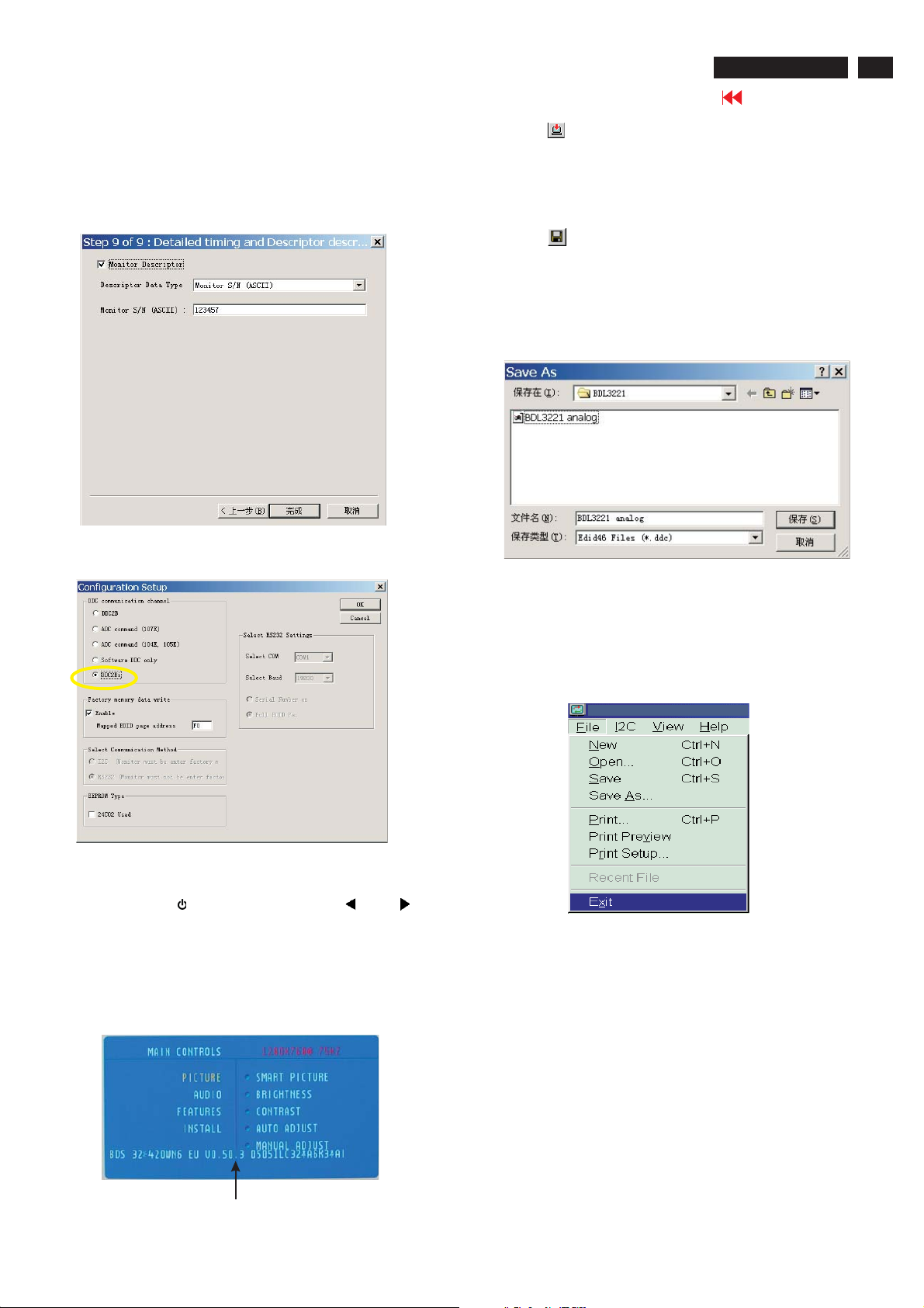
8. Click Next , bring up Fig. 22.
- Click Finish to exit the Step window.
- Serial number can be filled up at this moment (for example,
123457).
NOTE: You must modify the Serial NO. In step 9, otherwise the Serial NO.
In OSD Couldn't be modified correctly.
Fig. 22
Step 5: Write DDC data
1. Configuration should be as Fig. 23. And press OK.
4). Click (Write EDID) icon from the tool bar to write DDC data. Then
wait for a few minutes,DDC data will be finished Writing.
Step 6: Save DDC data
Sometimes, you may need to save DDC data as a text file
for using in other IC chip. To save DDC data, follow the
steps below:
1. Click (Save) icon (or click "file"-> "save as") from the tool
bar and give a file name as shown in Fig. 25.
The file type is EDID46 file (*.ddc) which can be open in
WordPad. By using WordPad, the texts of DDC data & table
(128 bytes, hex code) can be modified. If DDC TEXTS &
HEX Table ar completely correct, it can be saved as .ddc flie
to re-load it into DDC IC for DDC Data application.
Fig. 25
2. Access Factory Mode
1). Turn off monitor.
2).
Press power " " button.Then quickly push " " and " ",and
hold this two buttons , then the screen comes out "Waiting For
Automatic Adjustment ",then the screen will be black for one
second untill comes out "Windows screen"] => then release this
two buttons.
3). Press "MENU" button, wait until the OSD menu with
Characters "BDS 32*420WN6 EU V0.50.3 05051LC32*A
6K3*A1" (below OSD menu) come on the Screen of the
monitor.
2. Click Save.
Step 7: Exit DDC program
Pull down the File menu and select Exit as shown in Fig. 26.
Fig. 23
Fig. 26
Step 8: Turn off the monitor, exit the factory mode.
Factory Mode indicator
4) Push Menu to exit OSD menu.""
Fig. 24
Page 32
32
BDL3221 LCD/TV
Go to cover page
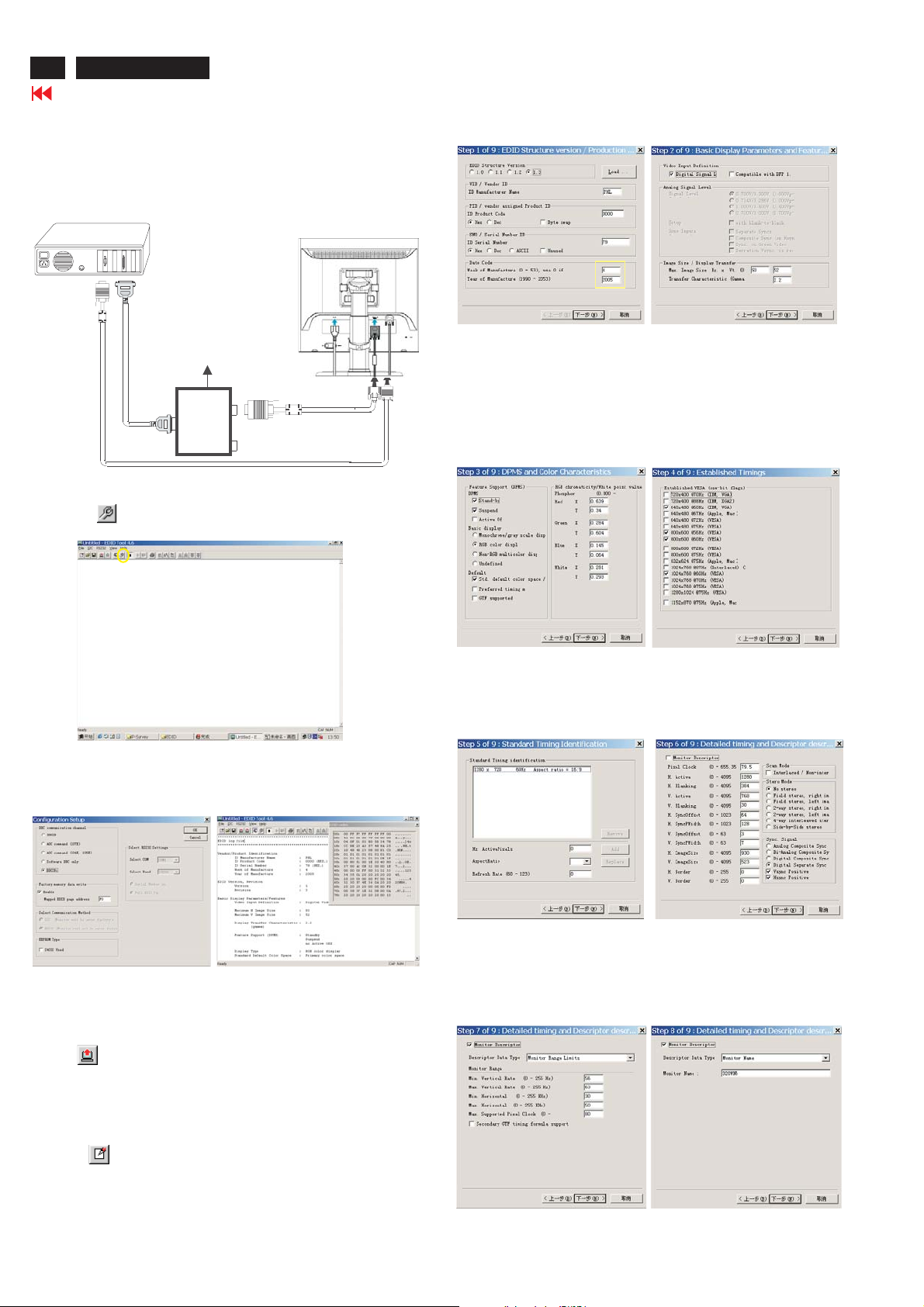
Re-programming Digital DDC IC
Step 1: After initialize alignment box, connecting all
cables and box as shown in Fig. 27.
PC
1=DVI-D connector
2=D-sub connector
3=Power Plug
DDC Instructions
Select and fill out,
If necessary.
DC Power
8 12V~
To video card
To printer port (LTP1)
Printer
Port
D-sub to DVI-D cable
To
Monitor
Step 2: Read DDC data from monitor
D-sub cable
3
1
2
Fig. 27
1. Click icon as shown in Fig. 11 from the tool bar to bring up
the Channels "Configuration Setup" windows as shown in Fig. 28.
=====>
Click this button
Fig. 28
2. Select the DDC2Bi as the communication channel.
As shown in Fig. 29.
Fig. 31
Step 4: Modify DDC data (Monitor Serial No.)
1. Click Next , bring up Fig. 32.
2. Click Next , bring up Fig. 33.
3. Click Next , bring up Fig. 34.
Fig. 33
4. Click Next , bring up Fig. 35.
5. Click Next , bring up Fig. 36.
Fig. 34
Fig. 32
Fig. 29
Fig. 30
3. Click OK button to confirm your selection.
4. Click icon (Read EDID function) to read DDC EDID data from
monitor. The EDID codes will display on screen as shown in Fig. 30.
Step 3: Modify DDC data (verify EDID version, week,
year)
Click (new function) icon from the tool bar, bring up
Step 1 of 9 as shown in Fig. 31 .
EDID46 DDC application provides the function selection and
text change (select & fill out) from Step 1 to Step 9.
Fig. 35
6. Click Next , bring up Fig. 37.
In this step, please confirm the Descriptor Data Type is
Monitor Range Limits, and all the items are same as below.
7. Click Next , bring up Fig. 38.
Fig. 37
Fig. 36
Fig. 38
Page 33
DDC Instructions
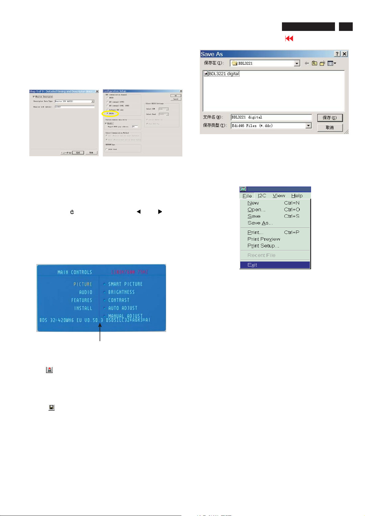
8. Click Next , bring up Fig. 39.
- Click Finish to exit the Step window.
- Serial number can be filled up at this moment (for example,
123457).
NOTE: You must modify the Serial NO. In step 9, otherwise the
Serial NO. In OSD Couldn't be modified correctly.
2. Click Save.
BDL3221 LCD/TV
Fig.42
33
Go to cover page
Fig. 39
Fig. 40
Step 5: Write DDC data
1. Configuration should be as Fig. 40. And press OK.
2. Access Factory Mode
1). Turn off monitor.
2).
Press power " " button.Then quickly push " " and " ",and
hold this two buttons , then the screen comes out "Waiting For
Automatic Adjustment ",then the screen will be black for one
second untill comes out "Windows screen"] => then release this
two buttons.
3). Press "MENU" button, wait until the OSD menu with
Characters "BDS 32*420WN6 EU V0.50.3 05051LC32*A
6K3*A1" (below OSD menu) come on the Screen of the
monitor.
Step 7: Exit DDC program
Pull down the File menu and select Exit as shown in Fig. 43.
Fig. 43
Step 8: Turn off the monitor, exit the factory mode.
Factory Mode indicator
Fig. 41
4) Push Menu to exit OSD menu.""
3. Click (Write EDID) icon from the tool bar to write DDC data. Then
wait for 20-30 seconds ,DDC data will be finished Writing.
Step 6: Save DDC data
Sometimes, you may need to save DDC data as a text file for using
in other IC chip. To save DDC data, follow the steps below:
1. Click (Save) icon (or click "file"-> "save as") from the tool bar and
give a file name as shown in Fig. 42.
The file type is EDID46 file (*.ddc) which can be open in WordPad. By
using WordPad, the texts of DDC data & table (128 bytes, hex
code) can be modified. If DDC TEXTS & HEX Table ar completely
correct, it can be saved as *.ddc flie to re-load it into DDC IC for DDC
Data application.
Page 34

34
BDL3221 LCD/TV
Go to cover page
DDC DATA
THE DISPLAY DATACHANNEL (DDC_2B) CONTENT INCLUDING:
(FOR BDL3221 ANALOG FOR LPL PANEL)
**********************************************************************
EDID log file
**********************************************************************
Vendor/Product Identification
ID Manufacturer Name : PHL
ID Product Code : 3408 (HEX. swap)
ID Serial Number : 79 (HEX.)
Week of Manufacture : 6
Year of Manufacture : 2005
EDID Version, Revision
Version : 1
Revision : 3
Basic Display Parameters/Features
Video Input Definition : Analog Video Input
0.700V/0.000V (0.70Vpp)
without Blank-to-Black Setup
Separate Sync
without Composite Sync
without Sync on Green
no Serration required
Maximum H Image Size : 69
Maximum V Image Size : 39
Display Transfer Characteristic : 2.2
(gamma)
Feature Support (DPMS) : Standby
Suspend
no Active Off
Display Type : RGB color display
Standard Default Color Space : Primary color space
Flags : Non-interlaced
: Normal Display, No stereo
: Digital Separate sync.
: Positive Vertical Sync.
: Positive Horizontal Sync.
Detailed Timing #2
Pixel Clock (MHz) : 84.75
H Active (pixels) : 1360
H Blanking (pixels) : 416
V Active (lines) : 768
V Blanking (lines) : 30
H Sync Offset (F Porch) (pixels) : 72
H Sync Pulse Width (pixels) : 136
V Sync Offset (F Porch) (lines) : 3
V Sync Pulse Width (lines) : 5
H Image Size (mm) : 697
V Image Size (mm) : 392
H Border (pixels) : 0
V Border (lines) : 0
Flags : Non-interlaced
: Normal Display, No stereo
: Digital Separate sync.
: Positive Vertical Sync.
: Positive Horizontal Sync.
Monitor Descriptor #3
Monitor Name : 320WN6
Monitor Descriptor #4
Monitor Range Limits
Min. Vt rate Hz : 50
Max. Vt rate Hz : 75
Min. Horiz. rate kHz : 30
Max. Horiz. rate kHz : 63
Max. Supported Pixel : 80
No secondary GTF timing formula supported.
Color Characteristics
Red X coordinate : 0.64
Red Y coordinate : 0.343
Green X coordinate : 0.28
Green Y coordinate : 0.605
Blue X coordinate : 0.145
Blue Y coordinate : 0.065
White X coordinate : 0.285
White Y coordinate : 0.293
Established Timings
Established Timings I : 640 x 480 @60Hz (IBM,VGA)
800 x 600 @56Hz (VESA)
800 x 600 @60Hz (VESA)
Established Timings II : 1024 x 768 @60Hz (VESA)
Manufacturer's timings :
Standard Timing Identification #1
Horizontal active pixels : 1280
Aspect Ratio : 16:9
Refresh Rate : 60
Detailed Timing #1
Pixel Clock (MHz) : 79.5
H Active (pixels) : 1280
H Blanking (pixels) : 384
V Active (lines) : 768
V Blanking (lines) : 30
H Sync Offset (F Porch) (pixels) : 64
H Sync Pulse Width (pixels) : 128
V Sync Offset (F Porch) (lines) : 3
V Sync Pulse Width (lines) : 7
H Image Size (mm) : 697
V Image Size (mm) : 392
H Border (pixels) : 0
V Border (lines) : 0
Extension Flag : 0
Check sum : 96 (HEX.)
**********************************************************************
EDID data (128 bytes)
**********************************************************************
0: 00 1: ff 2: ff 3: ff 4: ff 5: ff 6: ff 7: 00
8: 41 9: 0c 10: 34 11: 08 12: 79 13: 00 14: 00 15: 00
16: 06 17: 0f 18: 01 19: 03 20: 68 21: 45 22: 27 23: 78
24: cc 25: fc 26: 30 27: a3 28: 57 29: 47 30: 9b 31: 25
32: 10 33: 49 34: 4b 35: 23 36: 08 37: 00 38: 81 39: c0
40: 01 41: 01 42: 01 43: 01 44: 01 45: 01 46: 01 47: 01
48: 01 49: 01 50: 01 51: 01 52: 01 53: 01 54: 0e 55: 1f
56: 00 57: 80 58: 51 59: 00 60: 1e 61: 30 62: 40 63: 80
64: 37 65: 00 66: b9 67: 88 68: 21 69: 00 70: 00 71: 1e
72: 1b 73: 21 74: 50 75: a0 76: 51 77: 00 78: 1e 79: 30
80: 48 81: 88 82: 35 83: 00 84: b9 85: 88 86: 21 87: 00
88: 00 89: 1e 90: 00 91: 00 92: 00 93: fc 94: 00 95: 33
96: 32 97: 30 98: 57 99: 4e 100: 36 101: 0a 102: 20 103: 20
104: 20 105: 20 106: 20 107: 20 108: 00 109: 00 110: 00 111: fd
112: 00 113: 32 114: 4b 115: 1e 116: 3f 117: 08 118: 00 119: 0a
120: 20 121: 20 122: 20 123: 20 124: 20 125: 20 126: 00 127: 96
Page 35

DDC DATA
BDL3221 LCD/TV
Go to cover page
35
THE DISPLAY DATACHANNEL (DDC_2B) CONTENT INCLUDING:
(FOR BDL3221 DIGITAL FOR LPL PANEL)
**********************************************************************
EDID log file
**********************************************************************
Vendor/Product Identification
ID Manufacturer Name : PHL
ID Product Code : 3408 (HEX. swap)
ID Serial Number : 79 (HEX.)
Week of Manufacture : 6
Year of Manufacture : 2005
EDID Version, Revision
Version : 1
Revision : 3
Basic Display Parameters/Features
Video Input Definition : Digital Video Input
Maximum H Image Size : 69
Maximum V Image Size : 39
Display Transfer Characteristic : 2.2
(gamma)
Feature Support (DPMS) : Standby
Suspend
no Active Off
Display Type : RGB color display
Standard Default Color Space : Primary color space
Color Characteristics
Red X coordinate : 0.64
Red Y coordinate : 0.343
Green X coordinate : 0.28
Green Y coordinate : 0.605
Blue X coordinate : 0.145
Blue Y coordinate : 0.065
White X coordinate : 0.285
White Y coordinate : 0.293
Detailed Timing #2
Pixel Clock (MHz) : 84.75
H Active (pixels) : 1360
H Blanking (pixels) : 416
V Active (lines) : 768
V Blanking (lines) : 30
H Sync Offset (F Porch) (pixels) : 72
H Sync Pulse Width (pixels) : 136
V Sync Offset (F Porch) (lines) : 3
V Sync Pulse Width (lines) : 5
H Image Size (mm) : 697
V Image Size (mm) : 392
H Border (pixels) : 0
V Border (lines) : 0
Flags : Non-interlaced
: Normal Display, No stereo
: Digital Separate sync.
: Positive Vertical Sync.
: Positive Horizontal Sync.
Monitor Descriptor #3
Monitor Name : 320WN6
Monitor Descriptor #4
Monitor Range Limits
Min. Vt rate Hz : 50
Max. Vt rate Hz : 75
Min. Horiz. rate kHz : 30
Max. Horiz. rate kHz : 63
Max. Supported Pixel : 80
No secondary GTF timing formula supported.
Extension Flag : 0
Check sum : DF (HEX.)
**********************************************************************
EDID data (128 bytes)
**********************************************************************
Established Timings
Established Timings I : 640 x 480 @60Hz (IBM,VGA)
800 x 600 @56Hz (VESA)
800 x 600 @60Hz (VESA)
Established Timings II : 1024 x 768 @60Hz (VESA)
Manufacturer's timings :
Standard Timing Identification #1
Horizontal active pixels : 1280
Aspect Ratio : 16:9
Refresh Rate : 60
Detailed Timing #1
Pixel Clock (Mhz) : 74.5
H Active (pixels) : 1920
H Blanking (pixels) : 280
V Active (lines) : 1080
V Blanking (lines) : 45
H Sync Offset (F Porch) (pixels) : 44
H Sync Pulse Width (pixels) : 44
V Sync Offset (F Porch) (lines) : 2
V Sync Pulse Width (lines) : 5
H Image Size (mm) : 697
V Image Size (mm) : 392
H Border (pixels) : 0
V Border (lines) : 0
Flags : Interlaced
: Normal Display, No stereo
: Digital Separate sync.
: Positive Vertical Sync.
: Positive Horizontal Sync.
0: 00 1: ff 2: ff 3: ff 4: ff 5: ff 6: ff 7: 00
8: 41 9: 0c 10: 34 11: 08 12: 79 13: 00 14: 00 15: 00
16: 06 17: 0f 18: 01 19: 03 20: 80 21: 45 22: 27 23: 78
24: cc 25: fc 26: 30 27: a3 28: 57 29: 47 30: 9b 31: 25
32: 10 33: 49 34: 4b 35: 23 36: 08 37: 00 38: 81 39: c0
40: 01 41: 01 42: 01 43: 01 44: 01 45: 01 46: 01 47: 01
48: 01 49: 01 50: 01 51: 01 52: 01 53: 01 54: 1a 55: 1d
56: 80 57: 18 58: 71 59: 38 60: 2d 61: 40 62: 2c 63: 2c
64: 25 65: 00 66: b9 67: 88 68: 21 69: 00 70: 00 71: 9e
72: 1b 73: 21 74: 50 75: a0 76: 51 77: 00 78: 1e 79: 30
80: 48 81: 88 82: 35 83: 00 84: b9 85: 88 86: 21 87: 00
88: 00 89: 1e 90: 00 91: 00 92: 00 93: fc 94: 00 95: 33
96: 32 97: 30 98: 57 99: 4e 100: 36 101: 0a 102: 20 103: 20
104: 20 105: 20 106: 20 107: 20 108: 00 109: 00 110: 00 111: fd
112: 00 113: 32 114: 4b 115: 1e 116: 3f 117: 08 118: 00 119: 0a
120: 20 121: 20 122: 20 123: 20 124: 20 125: 20 126: 00 127: df
Page 36
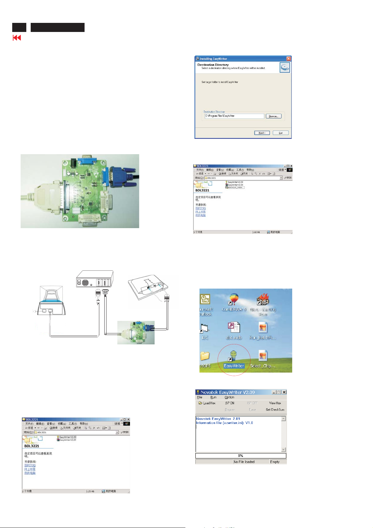
36
BDL3221 LCD/TV
ISP Instructions
Go to cover page
Configuration and procedure
"Easywriter " The software is provided by Novatek to upgrade the
firmware of CPU.
It is a windows-based program, which cannot be run in MS-DOS.
DDC2BI_ISP TOOL (3138 149 53161) is for the interface between
"Parallel Port of PC" and "15 pin-D-SUB connector of Monitor".
System and equipment requirements
1. An i486 (or above) personal computer or compatible.
2. Microsoft operation system Windows 95/98/2000/XP.
3. ISP Software " Easywrite "
4. as shown in Fig. 1
DDC2BI_ISP TOOL (3138 106 10396)
D-SUB to monitor
Parallel Port to Print Port in PC
Fig. 4
Step 5 :Copy the BDS42AP_V094_5826 to C:\320WN6 as shown in Fig.
5.
Fig. 1
5. Connect and Mains cord to Monitor as shown
in Fig. 2.
Connect to
Mains cord
6. Install and setup the Easywriter program
Step 1 : Make a folder in your PC as shown in Fig. 3.
Step 2 : Copy ISP Software Easywriter into your folder
Step 3 : Unzip Easywriter.zip into your folder as shown in Fig. 3.
Step 4 : Double click the EasywriterV2.09a_user.exe icon to install the
DDC2BI_ISP TOOL
Monitor (A)
Video cable
Fig.2
For example : C:\BDL3221
as shown in Fig.3.
Application as Fig. 4.
PC
To video card
.zip
320WN6 -Monitor (B)
Connect to Mains
cord at this moment.
ISP box
To printer port (LTP1)
D-Sub
------------------------------->
Fig. 5
Update the firmware
1. Double click the Easywriter.exe icon in desktop then appears
window as shown in Fig.7 .
Fig. 6
Fig. 3
Fig. 7
2. Press the Load hex then select the hex as shown in Fig. 8.
Page 37
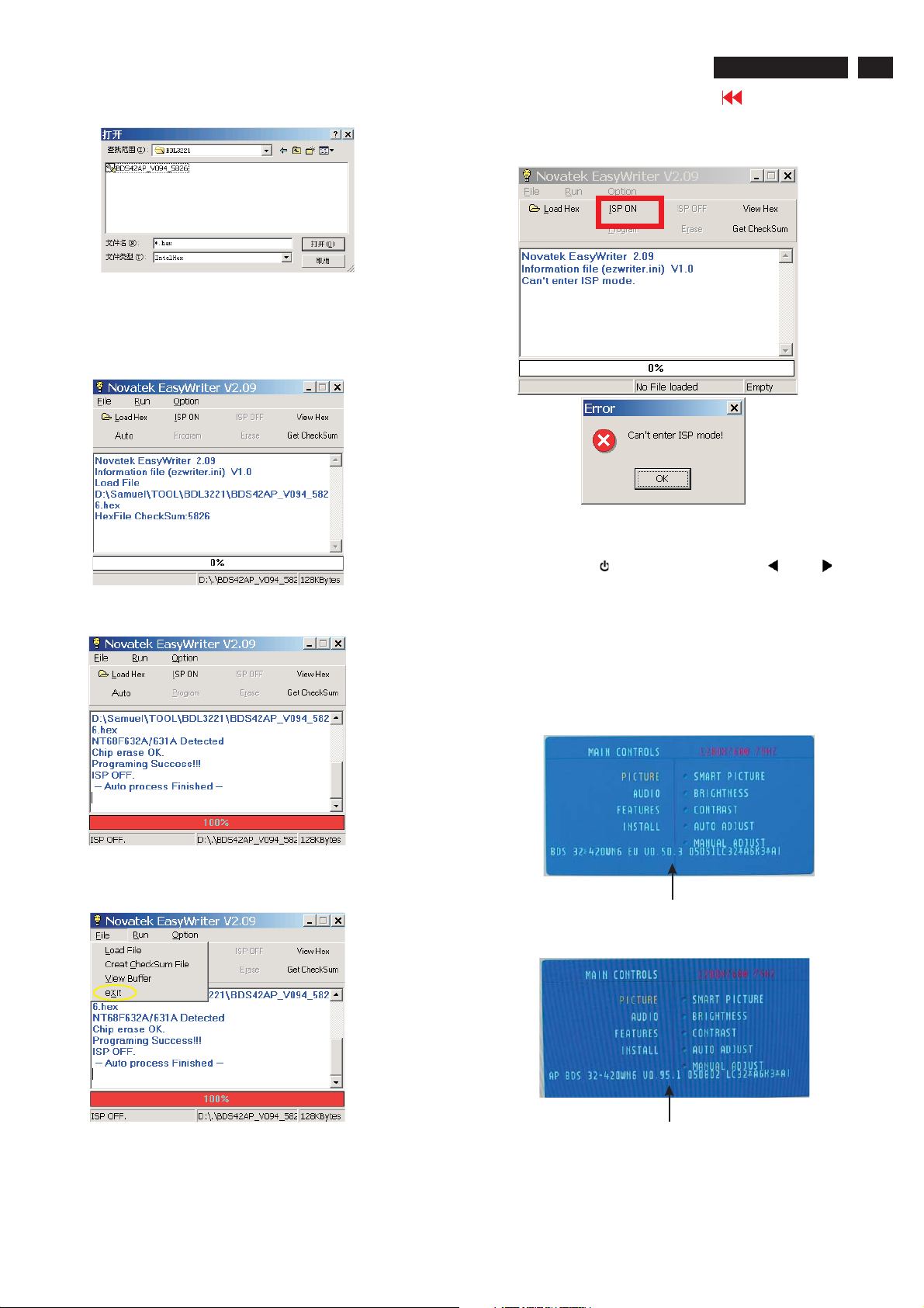
ISP Instructions
Fig. 8
3 Press the AUTO to running program , the firmware be updated
as shown in Fig. 9~10.
BDL3221 LCD/TV
Go to cover page
If there is a warring message coming as shown in Fig 12. , you
have to check the AC power, Video cable, or Novatek MCU.
Fig. 12
5 Check the firmware version
37
Fig. 9
Fig. 10
4 Press the file --> exit to end program , as shown in Fig. 11.
1). Turn off monitor.
Press power " " button.Then quickly push " " and " ",and
2).
hold this two buttons , then the screen comes out "Waiting For
Automatic Adjustment ",then the screen will be black for one
second untill comes out "Windows screen"] => then release this
two buttons.
3). Press "MENU" button, wait until the OSD menu come on the
Screen of the monitor.You will find, after upgrade, the version
have already changed from The former"BDS 32*420WN6 EU
V0.50.3 05051LC32*A6K3*A1" to the Present "AP BDS 32420WN6 V0.95.1 050802 LC32*A6K3*A1"as shown in Fig. 13
and Fig. 14.
Fig. 13
Factory Mode indicator
Fig. 11
Fig. 14
Factory Mode indicator
4) Turn off the monitor, exit the factory mode.
Page 38
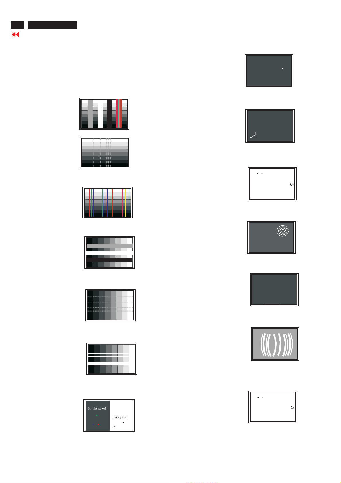
38
BDL3221 LCD/TV
Failure Mode Of Panel
Go to cover page
Quick reference for failure mode of LCD panel
this page presents problems that could be made by LCD panel.
It is not necessary to repair circuit board. Simply follow the mechanical
instruction on this manual to eliminate failure by replace LCD panel.
Polarizer has bubbles
Failure description
Vertical block defect
Vertical dim lines
Vertical lines defect
(Always bright or dark)
Horizontal block defect
Phenomenon
Polarizer has bubbles
Foreign material inside
polarizer. It shows liner or
dot shape.
Concentric circle formed
Horizontal dim lines
Horizontal lines defect
(Always bright or dark)
Has bright or dark pixel
Bottom back light of LCD is
brighter than normal
Back light un-uniformity
Backlight has foreign material.
Black or white color, liner or
circular type
Page 39
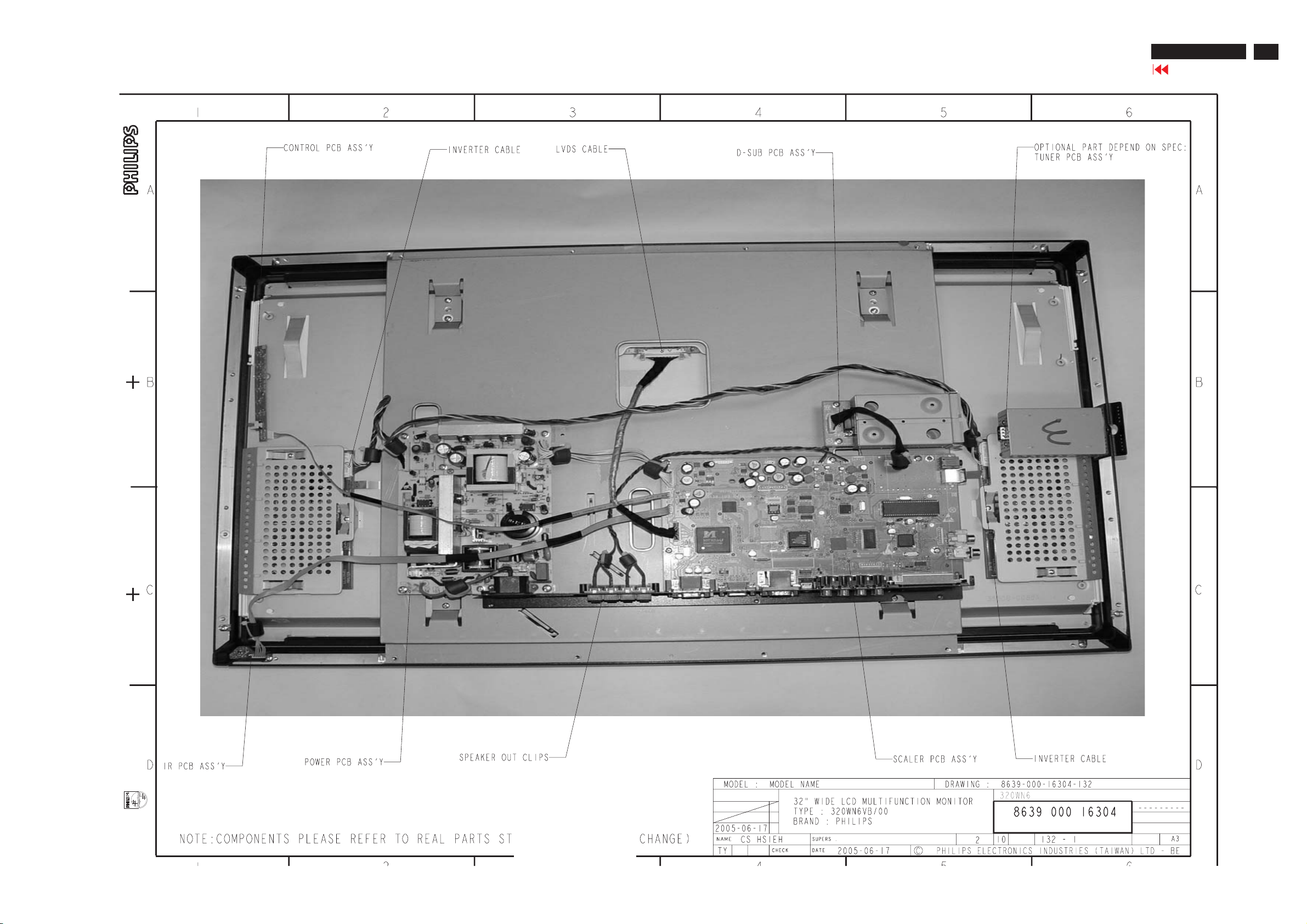
Wiring Diagram
BDL 3221 LCD/TV
Go to cover page
39
Page 40
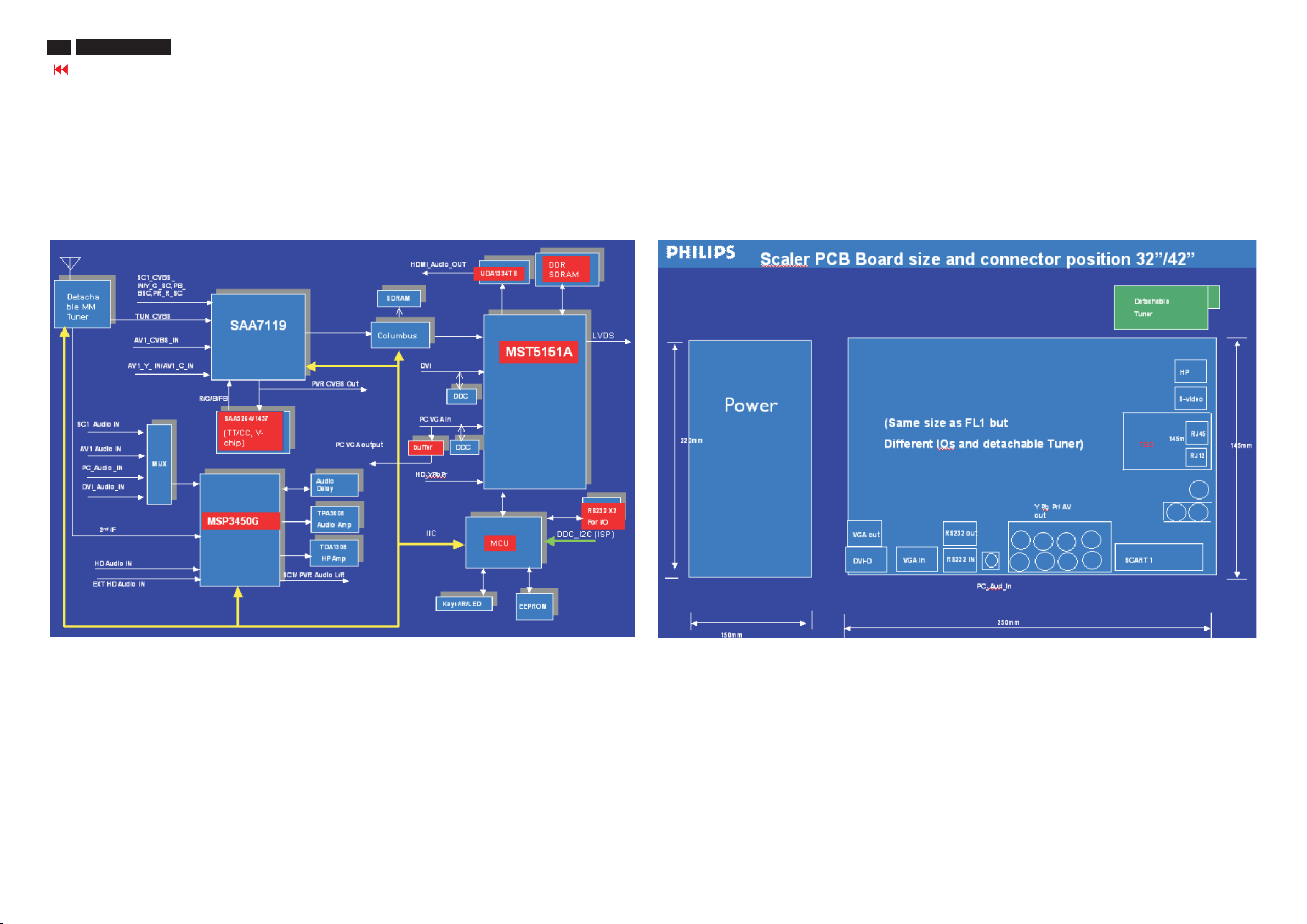
BDL 3221 LCD/TV
40
Go to cover page
Block Diagram
Main board
Architecture of LCD TV Monitor
(BackView ) PCB dimension & connectors position
Page 41
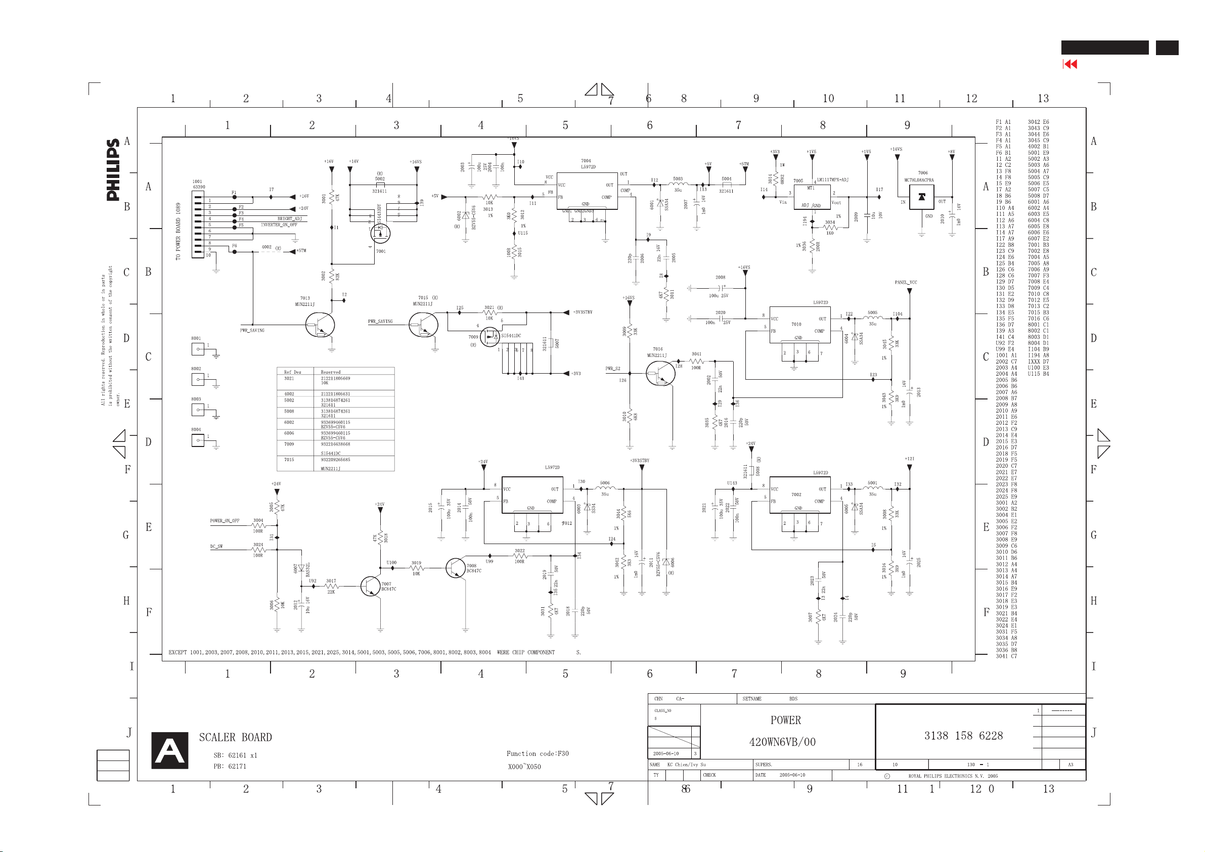
Scaler Diagram-1
BDL 3221 LCD/TV
Go to cover page
41
Page 42
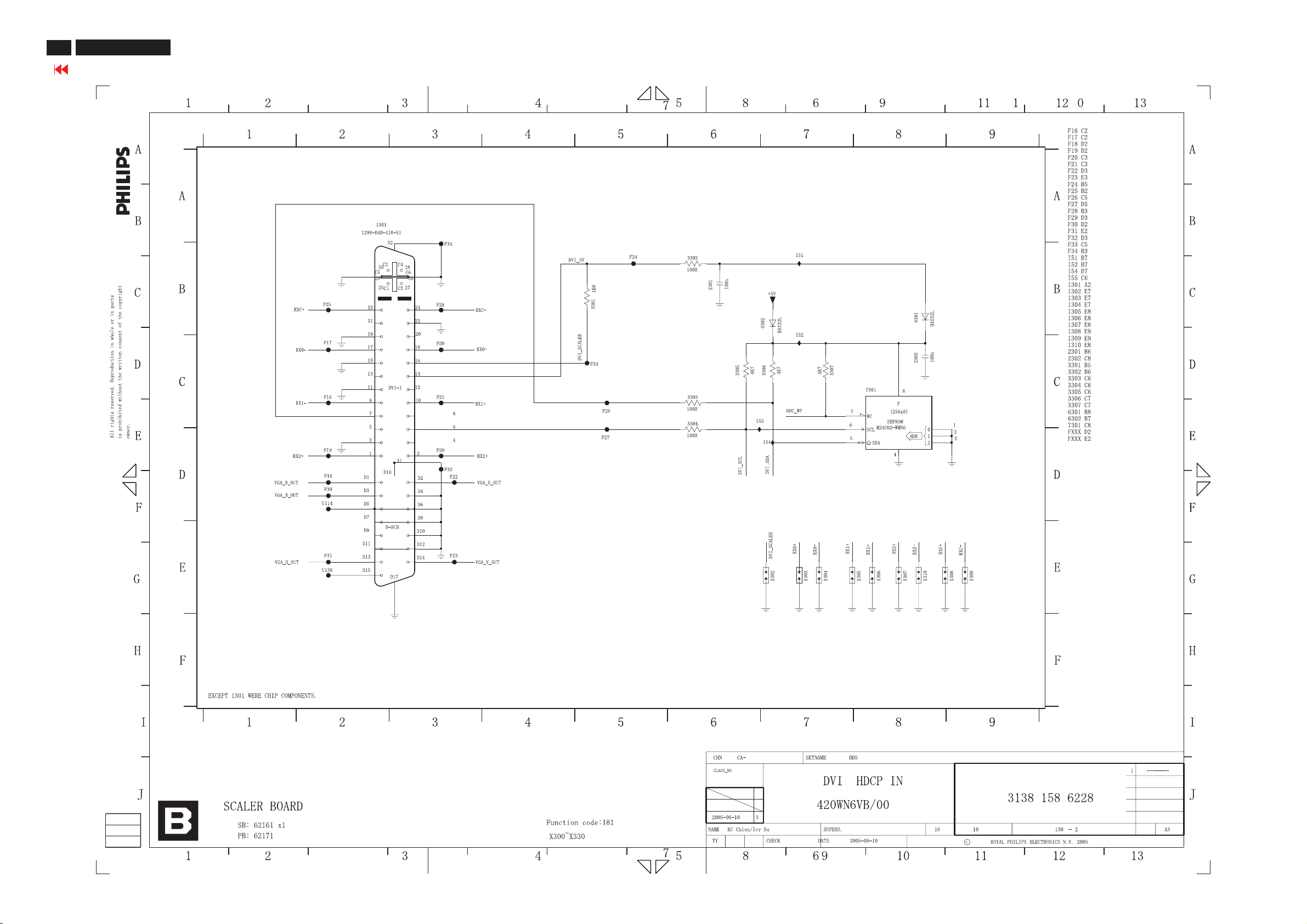
BDL 3221 LCD/TV
42
Go to cover page
Scaler Diagram-2
Page 43
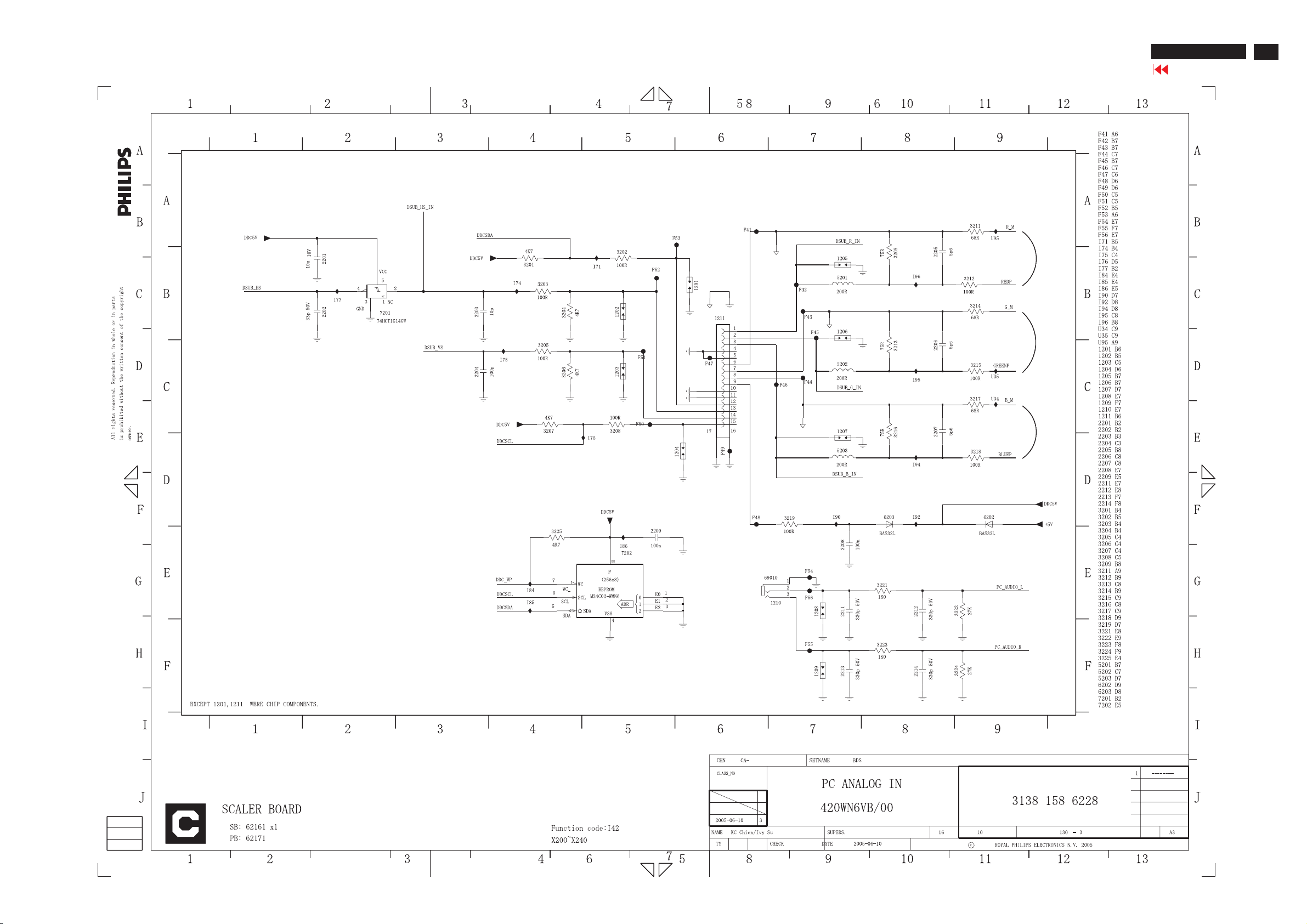
Scaler Diagram-3
BDL 3221 LCD/TV
Go to cover page
43
Page 44
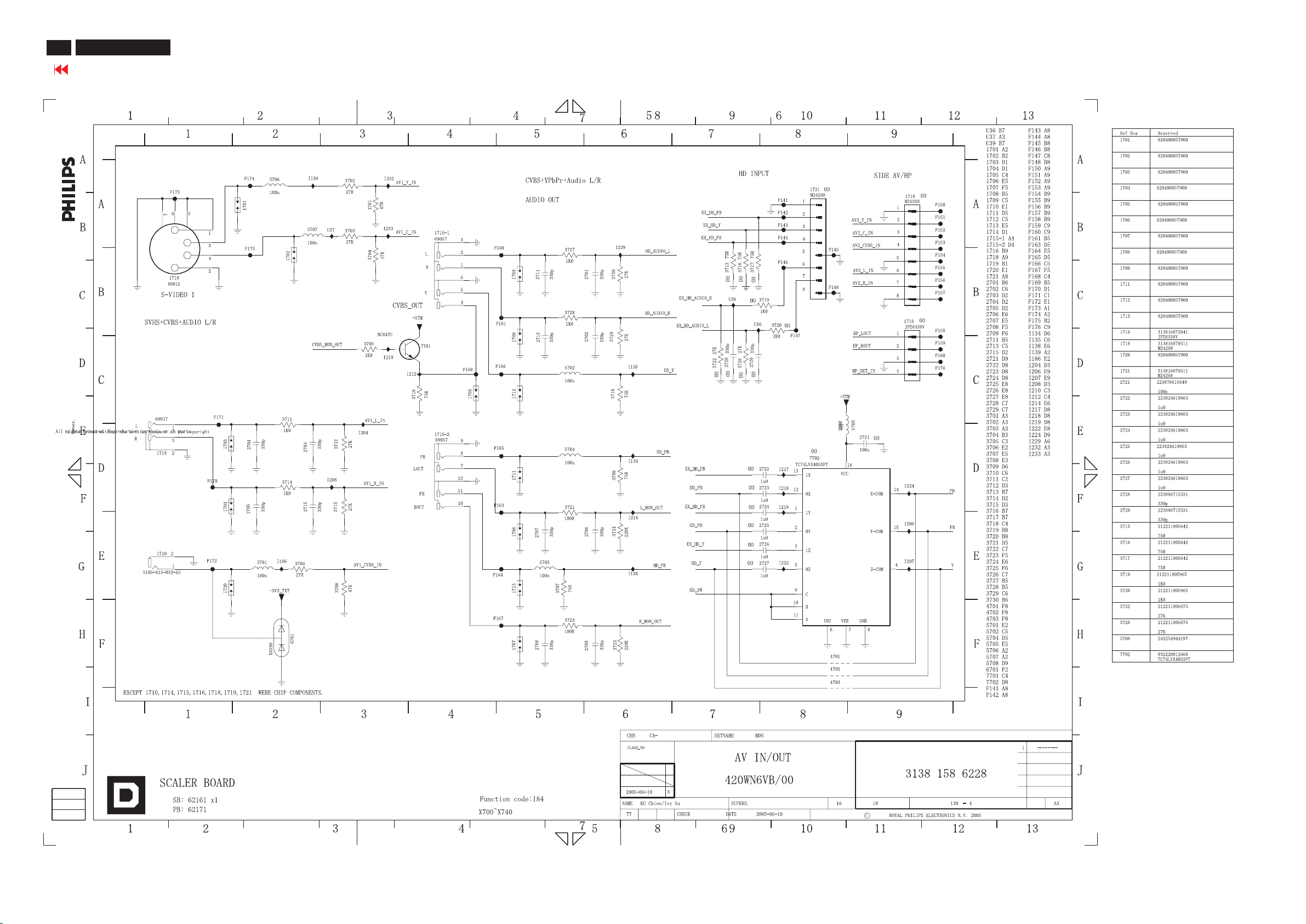
BDL 3221 LCD/TV
44
Go to cover page
Scaler Diagram-4
Page 45
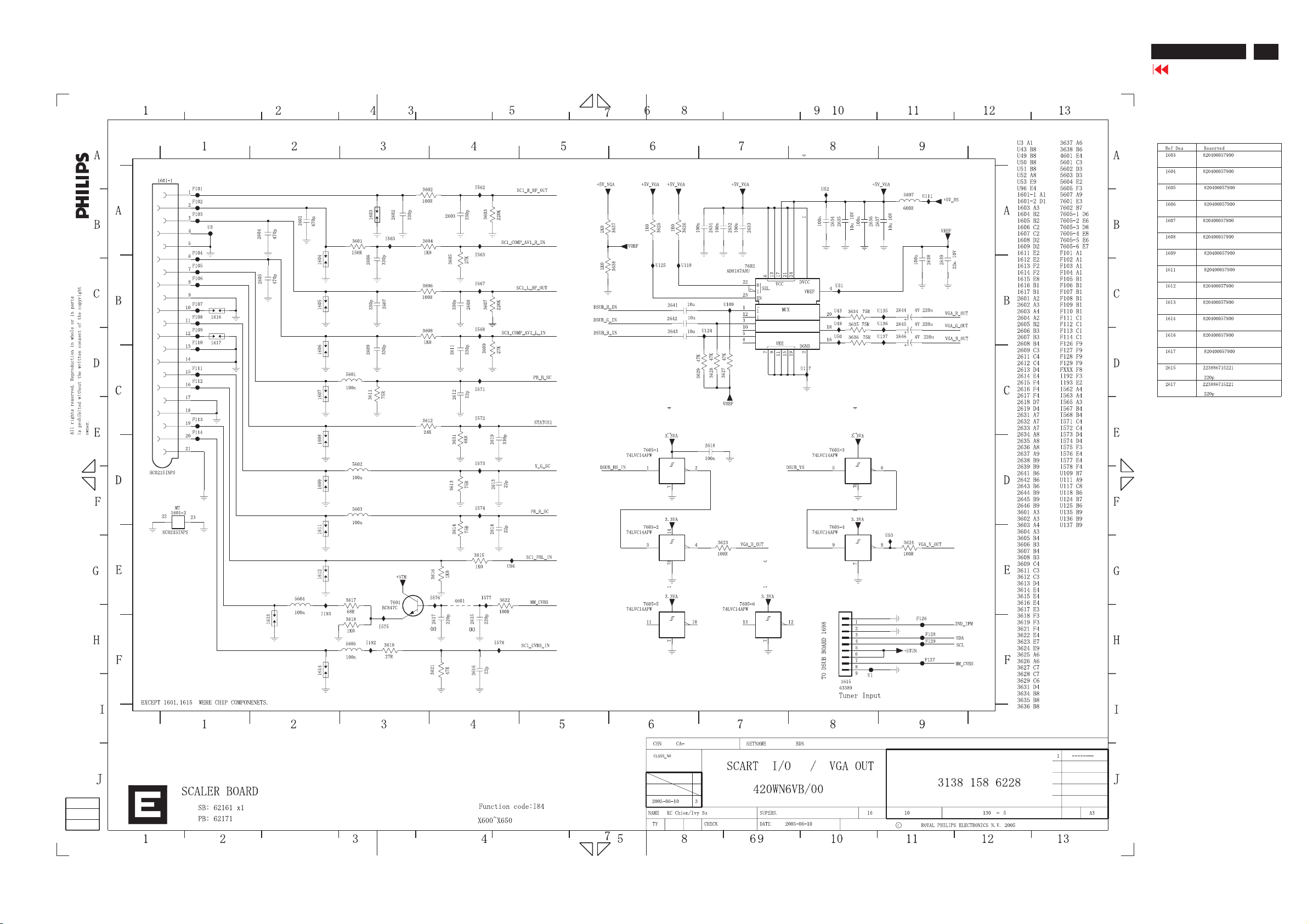
Scaler Diagram-5
BDL 3221 LCD/TV
Go to cover page
45
Page 46
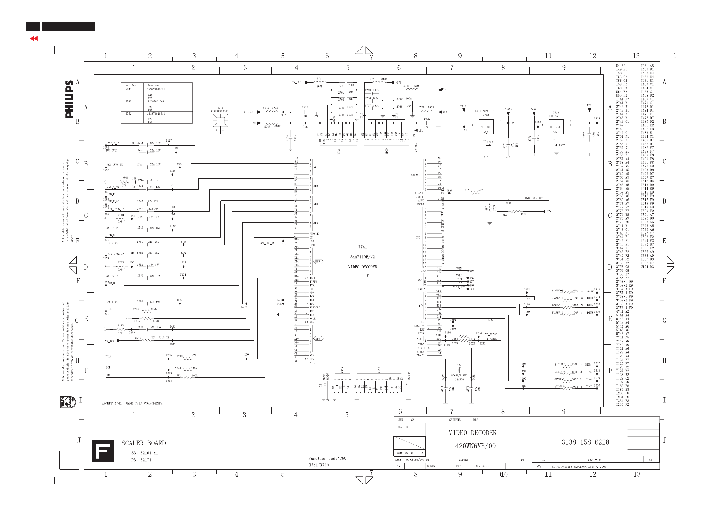
BDL 3221 LCD/TV
46
Go to cover page
Scaler Diagram-6
Page 47
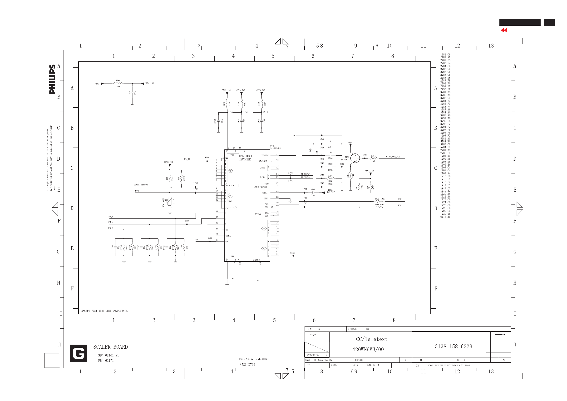
Scaler Diagram-7
BDL 3221 LCD/TV
Go to cover page
47
Page 48
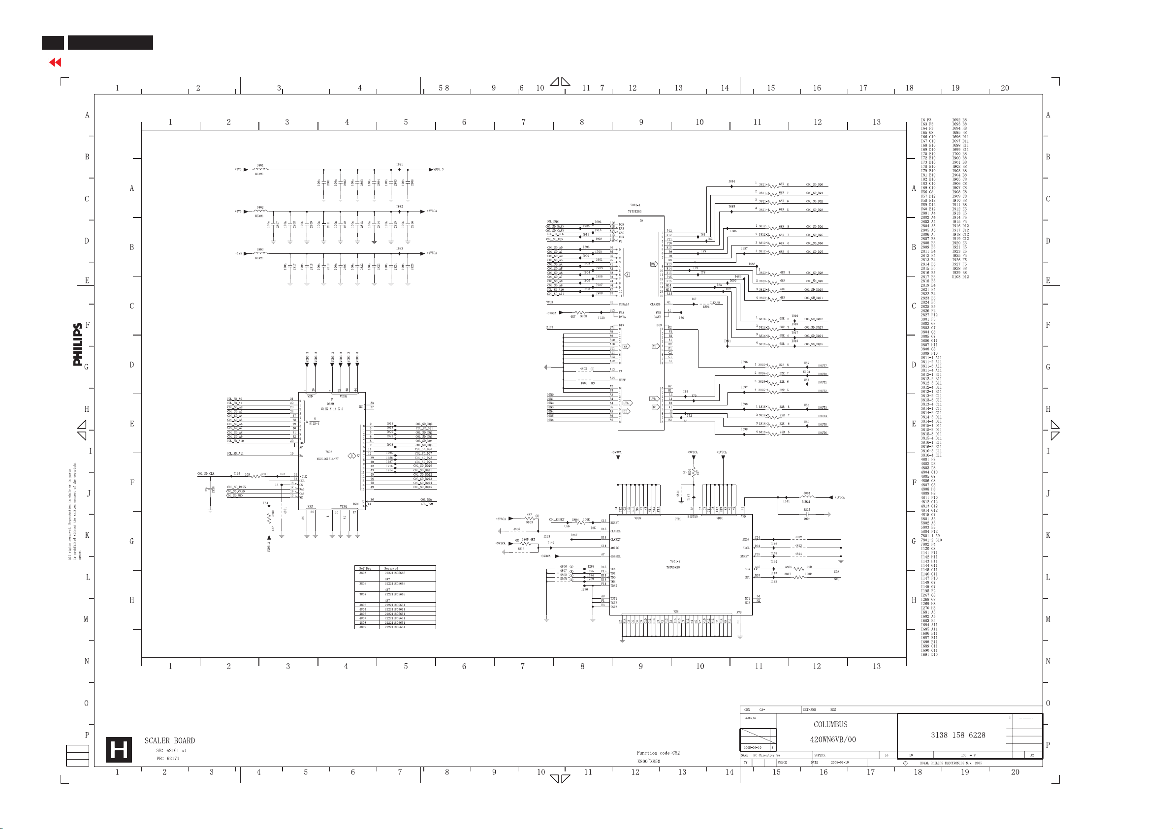
BDL 3221 LCD/TV
48
Go to cover page
Scaler Diagram-8
Page 49

Scaler Diagram-9
BDL 3221 LCD/TV
Go to cover page
49
Page 50
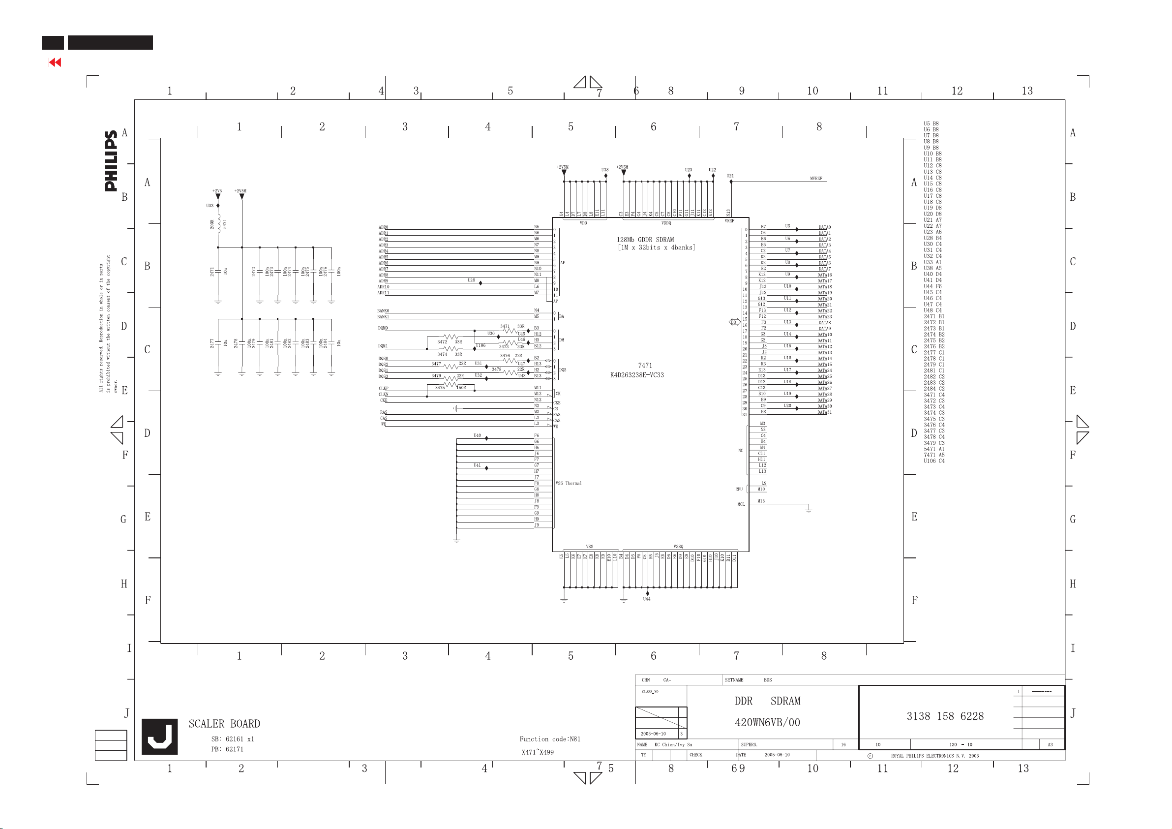
BDL 3221 LCD/TV
50
Go to cover page
Scaler Diagram-10
Page 51
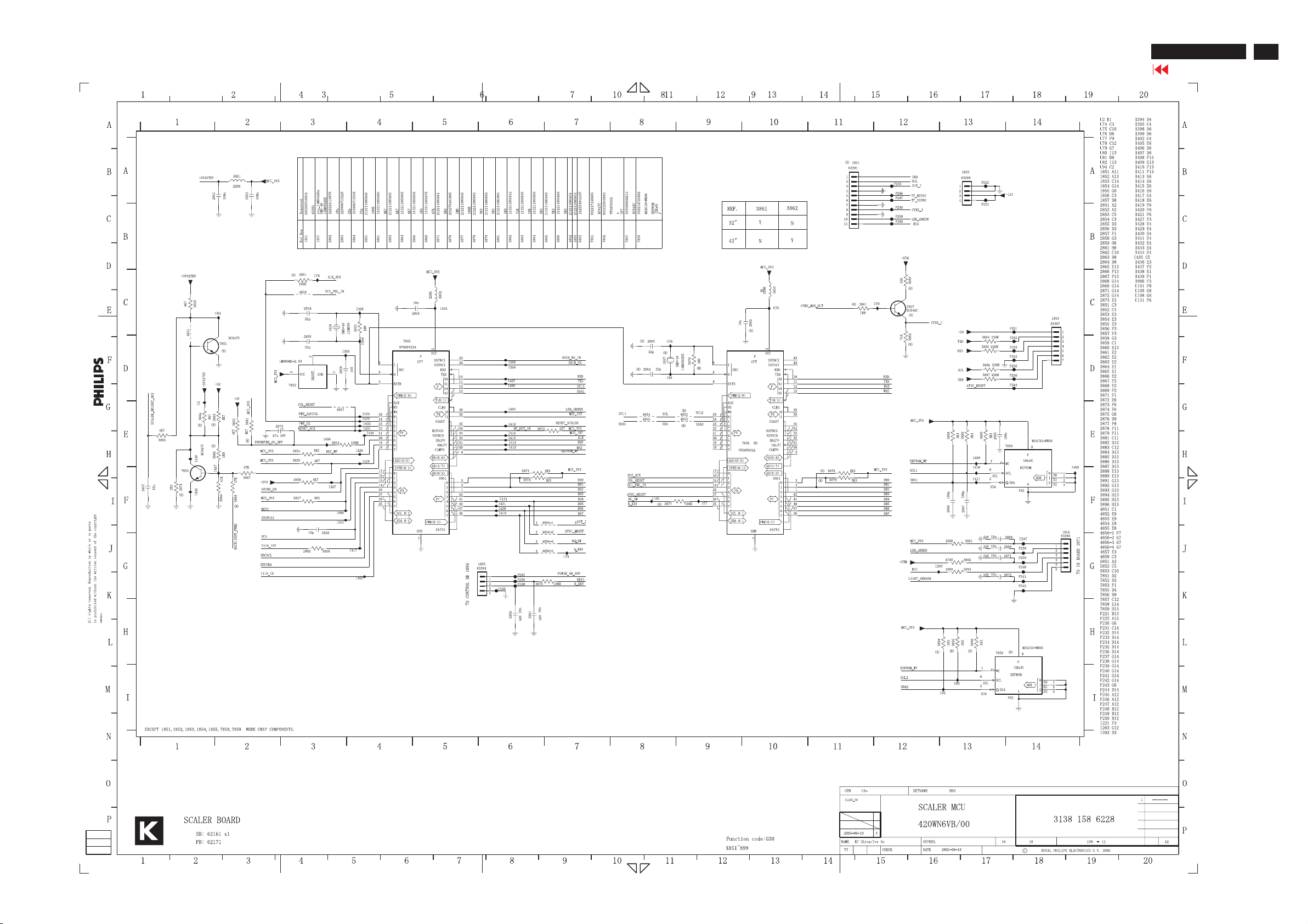
Scaler Diagram-11
BDL 3221 LCD/TV
Go to cover page
51
Page 52
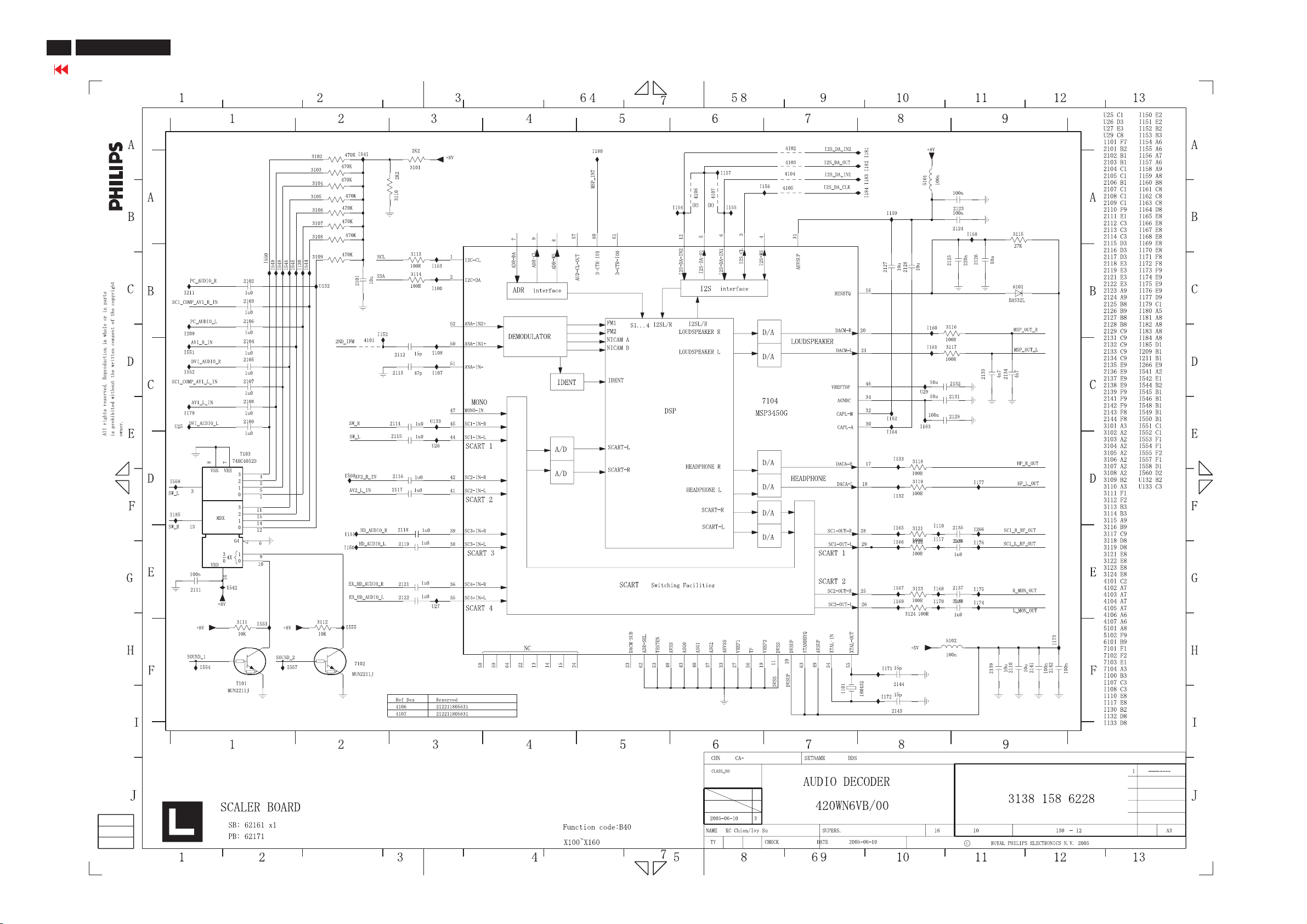
BDL 3221 LCD/TV
52
Go to cover page
Scaler Diagram-12
Page 53
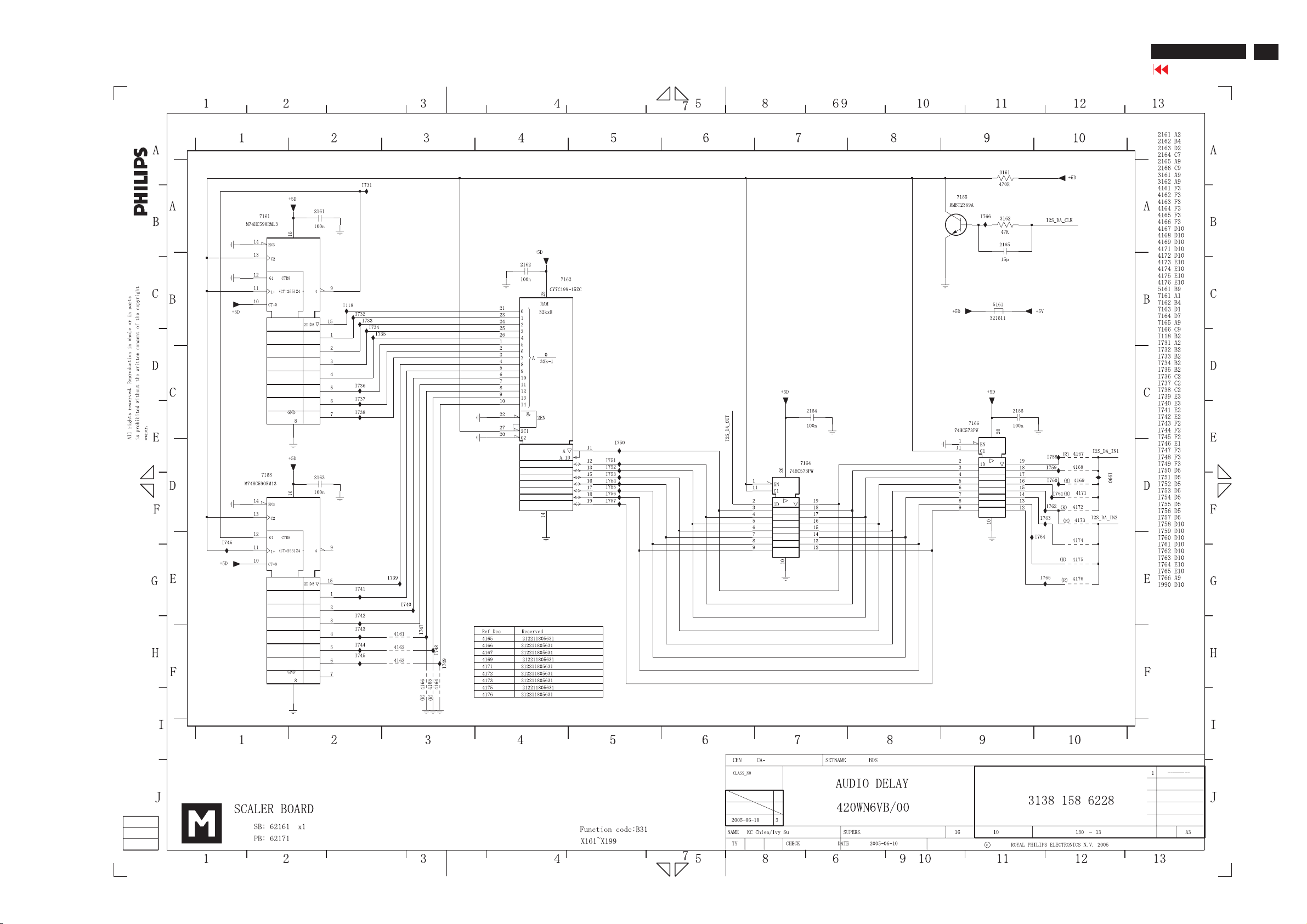
Scaler Diagram-13
BDL 3221 LCD/TV
Go to cover page
53
Page 54
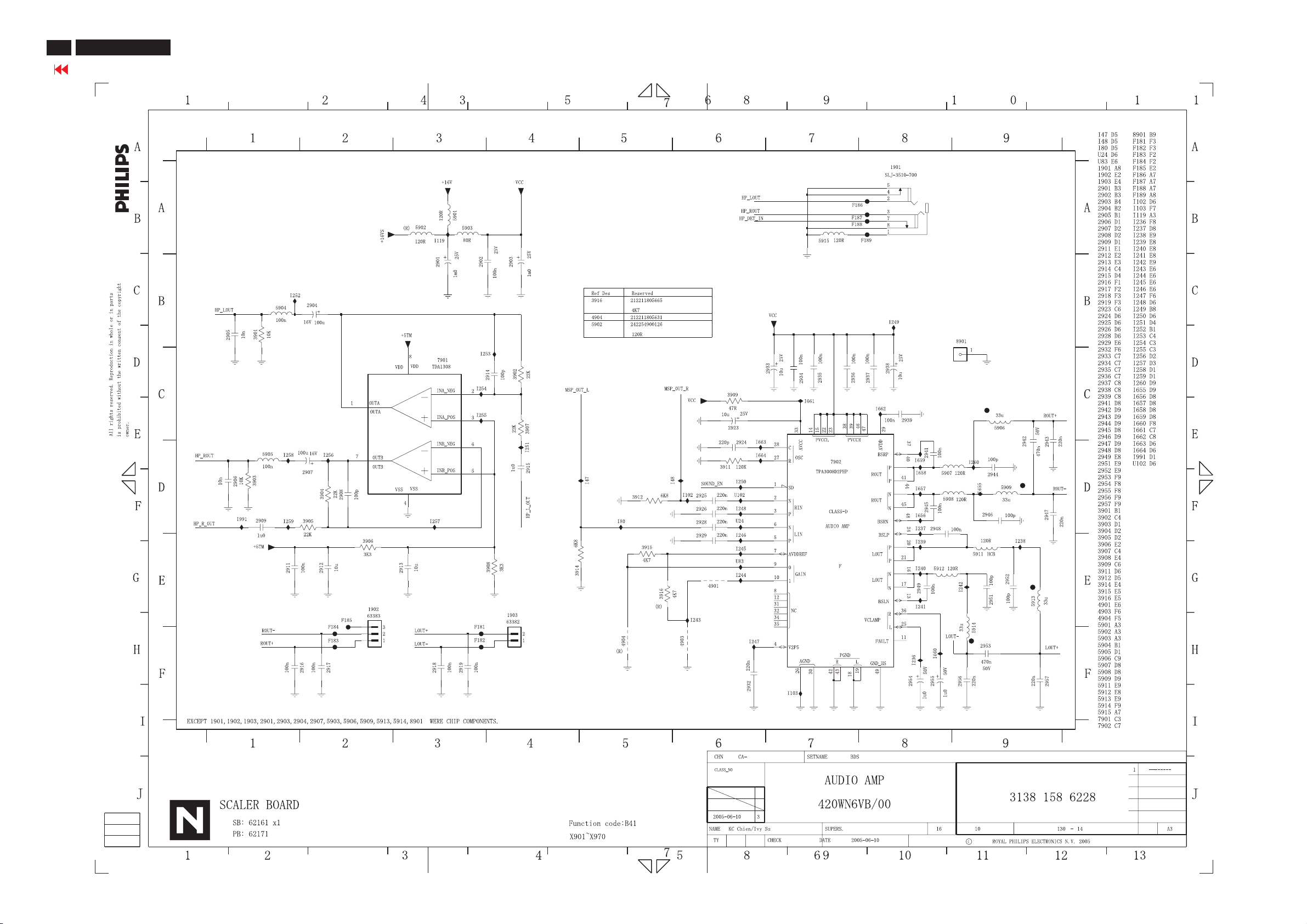
BDL 3221 LCD/TV
54
Go to cover page
Scaler Diagram-14
Page 55
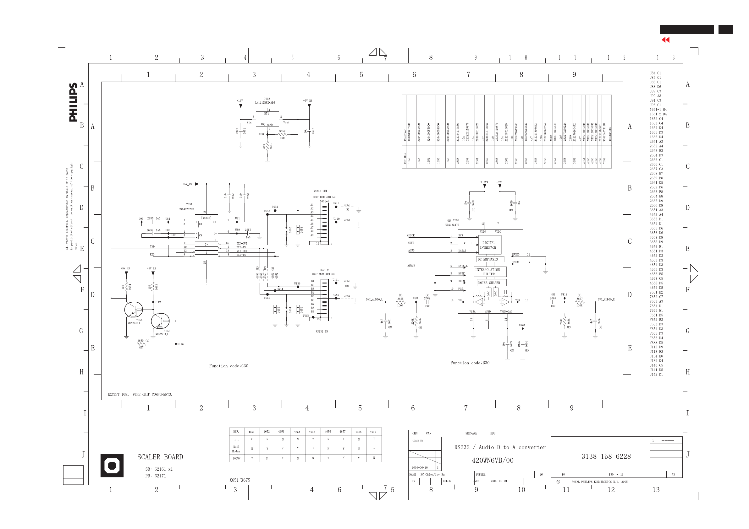
Scaler Diagram-15
BDL 3221 LCD/TV
Go to cover page
55
Page 56
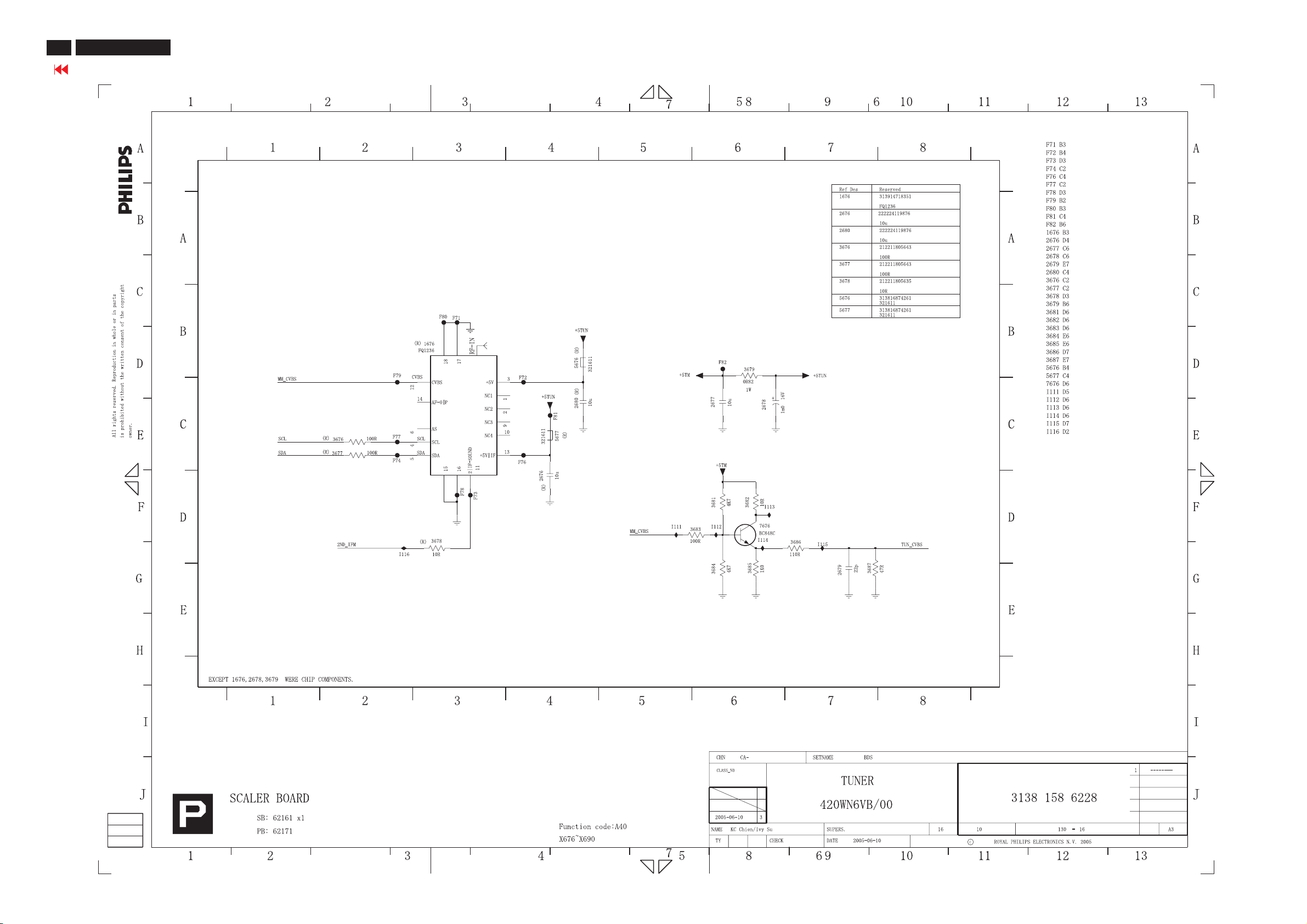
BDL 3221 LCD/TV
56
Go to cover page
Scaler Diagram-16
Page 57
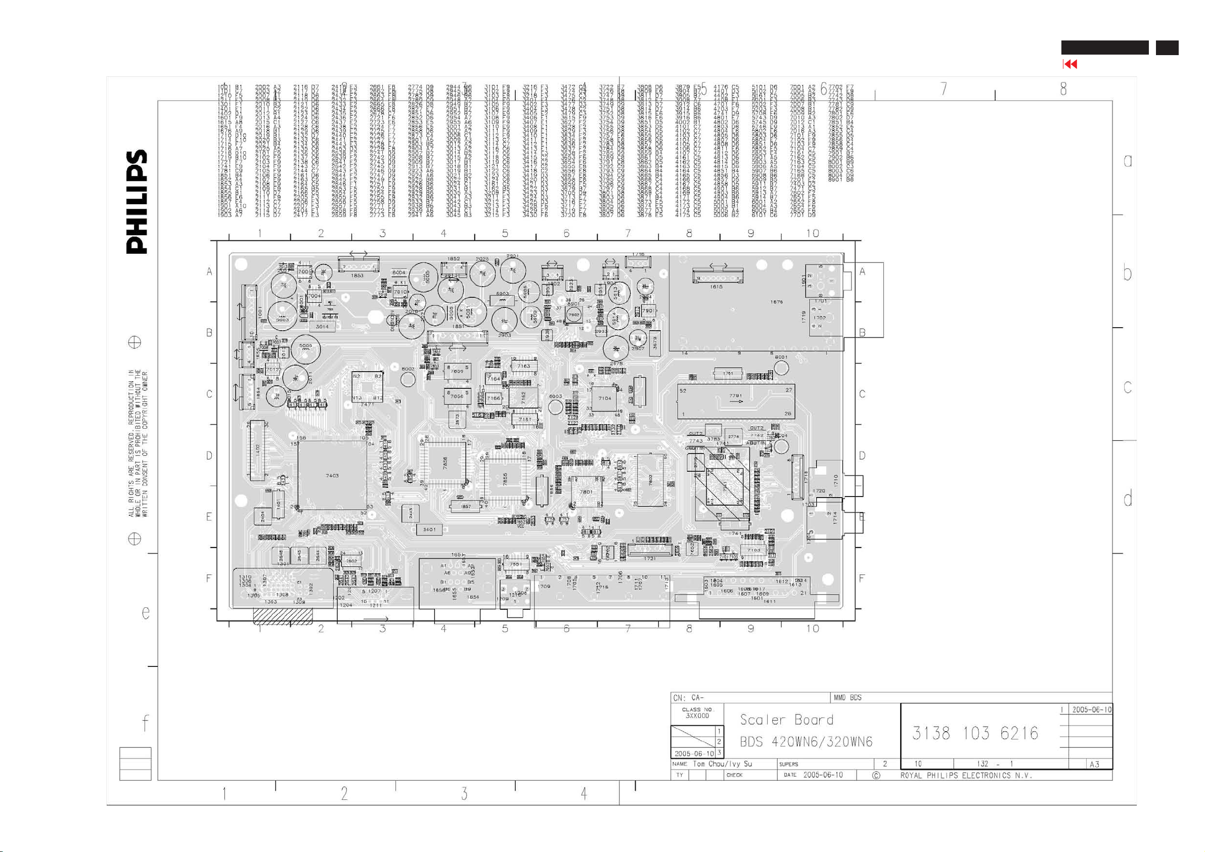
Scaler Board C.B.A.-1
BDL 3221 LCD/TV
Go to cover page
57
Page 58
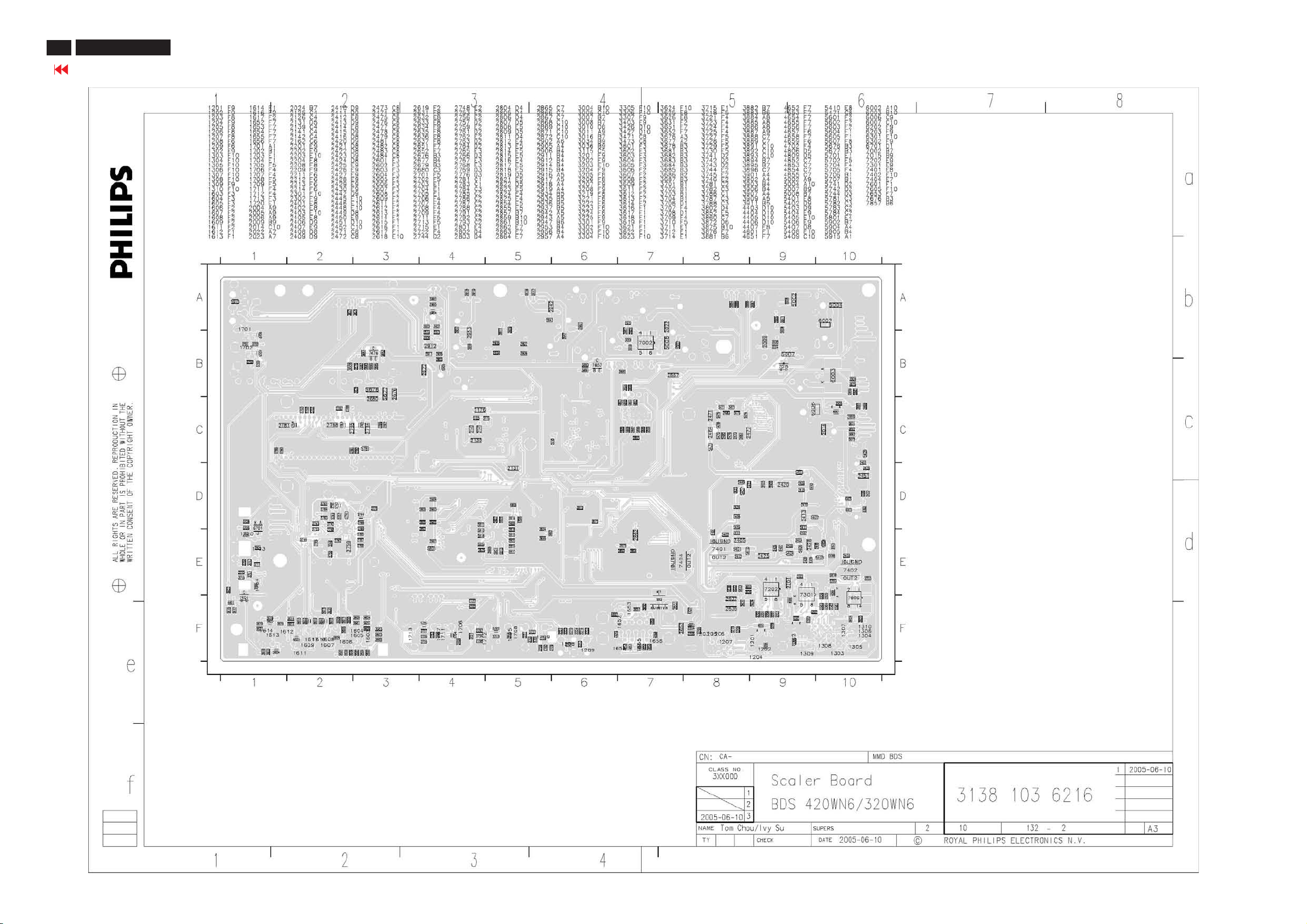
BDL 3221 LCD/TV
58
Go to cover page
Scaler Board C.B.A.-2
Page 59
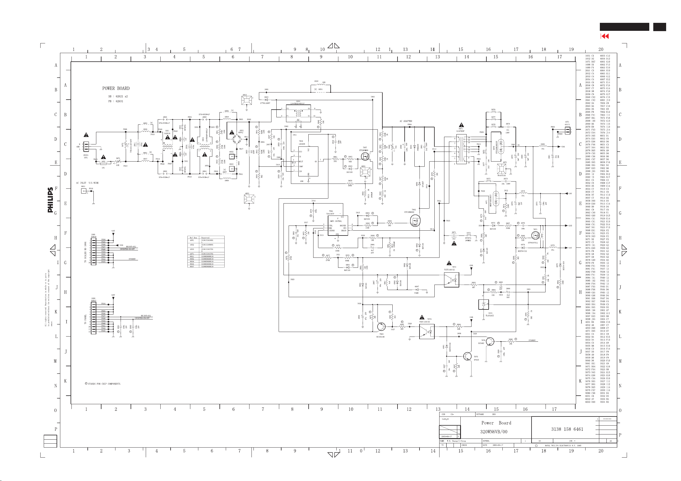
Power Diagram
BDL 3221 LCD/TV
Go to cover page
59
Page 60
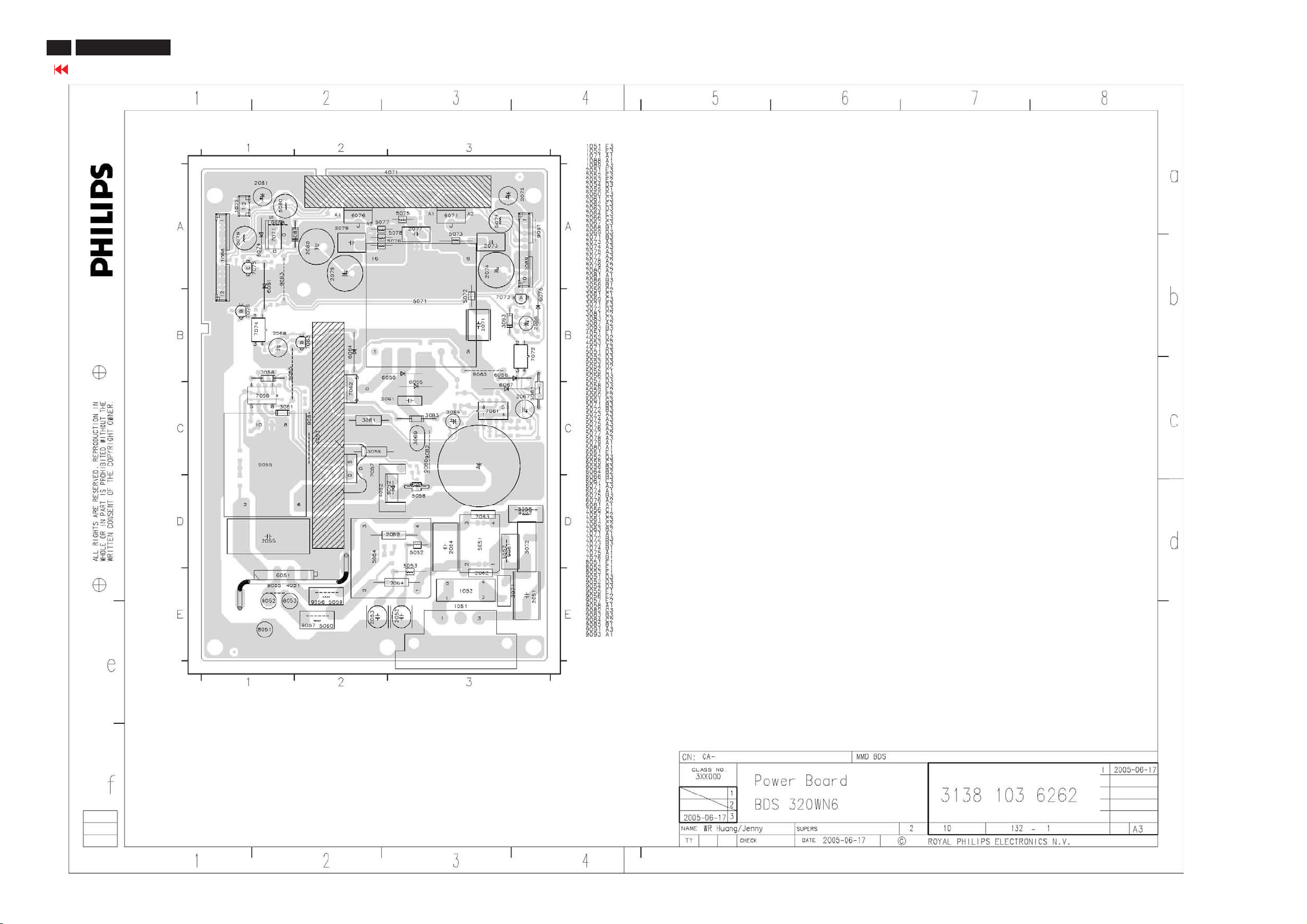
BDL 3221 LCD/TV
60
Go to cover page
Power Board C.B.A.-1
Page 61
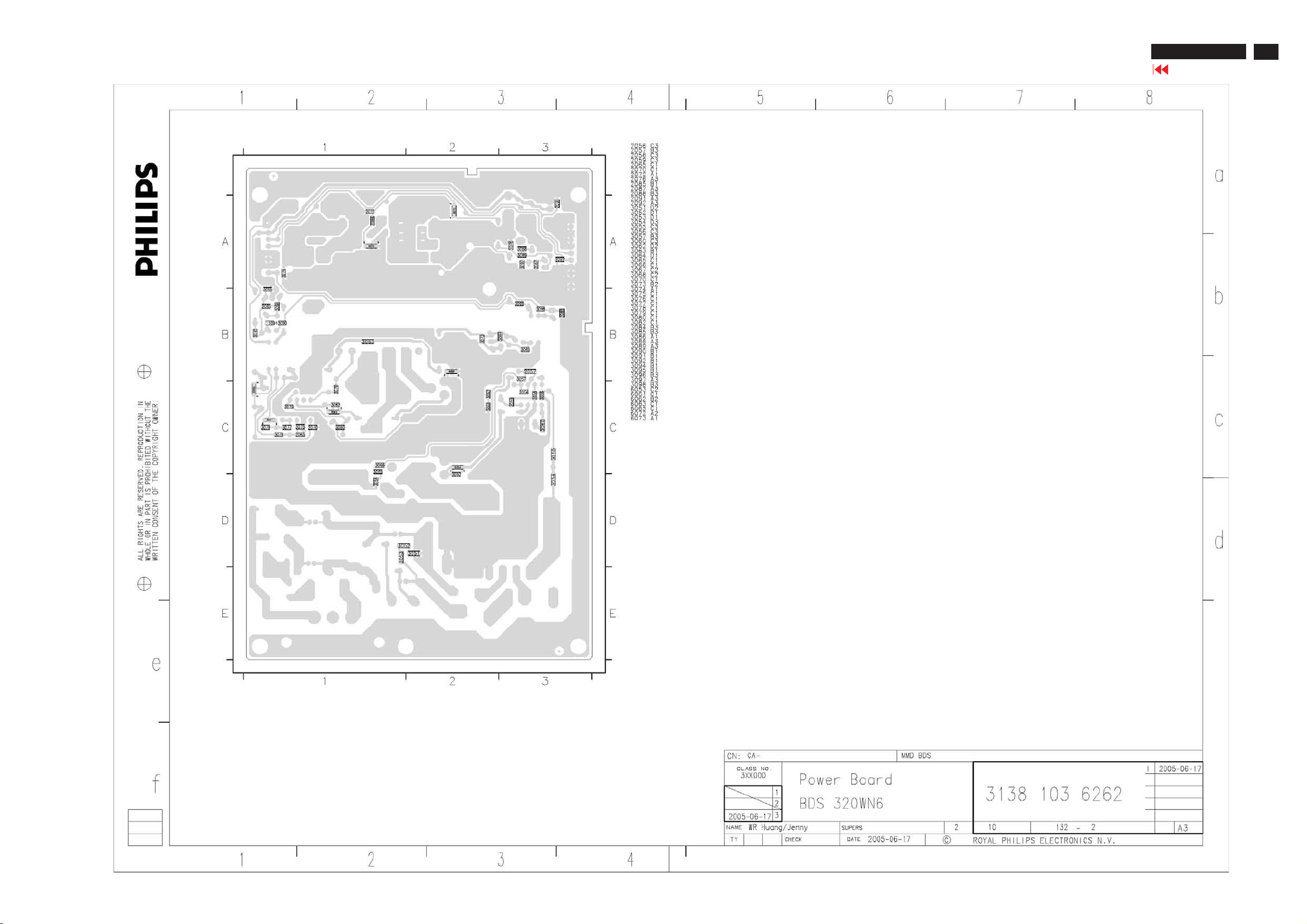
Power Board C.B.A.-2
BDL 3221 LCD/TV
Go to cover page
61
Page 62
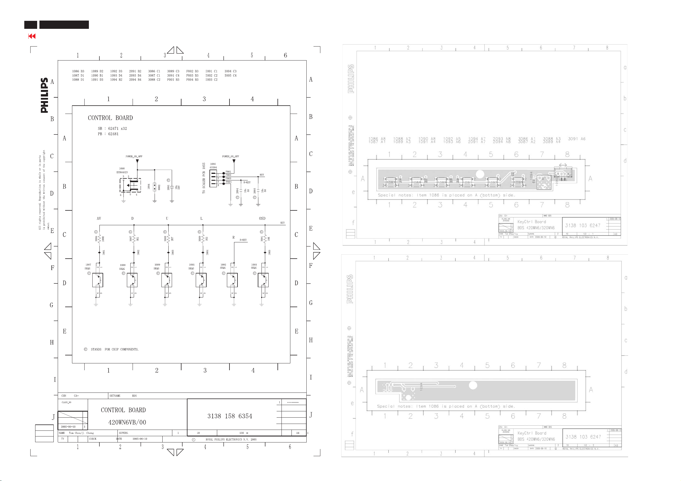
BDL 3221 LCD/TV
62
Go to cover page
Control Diagram&C.B.A
Page 63
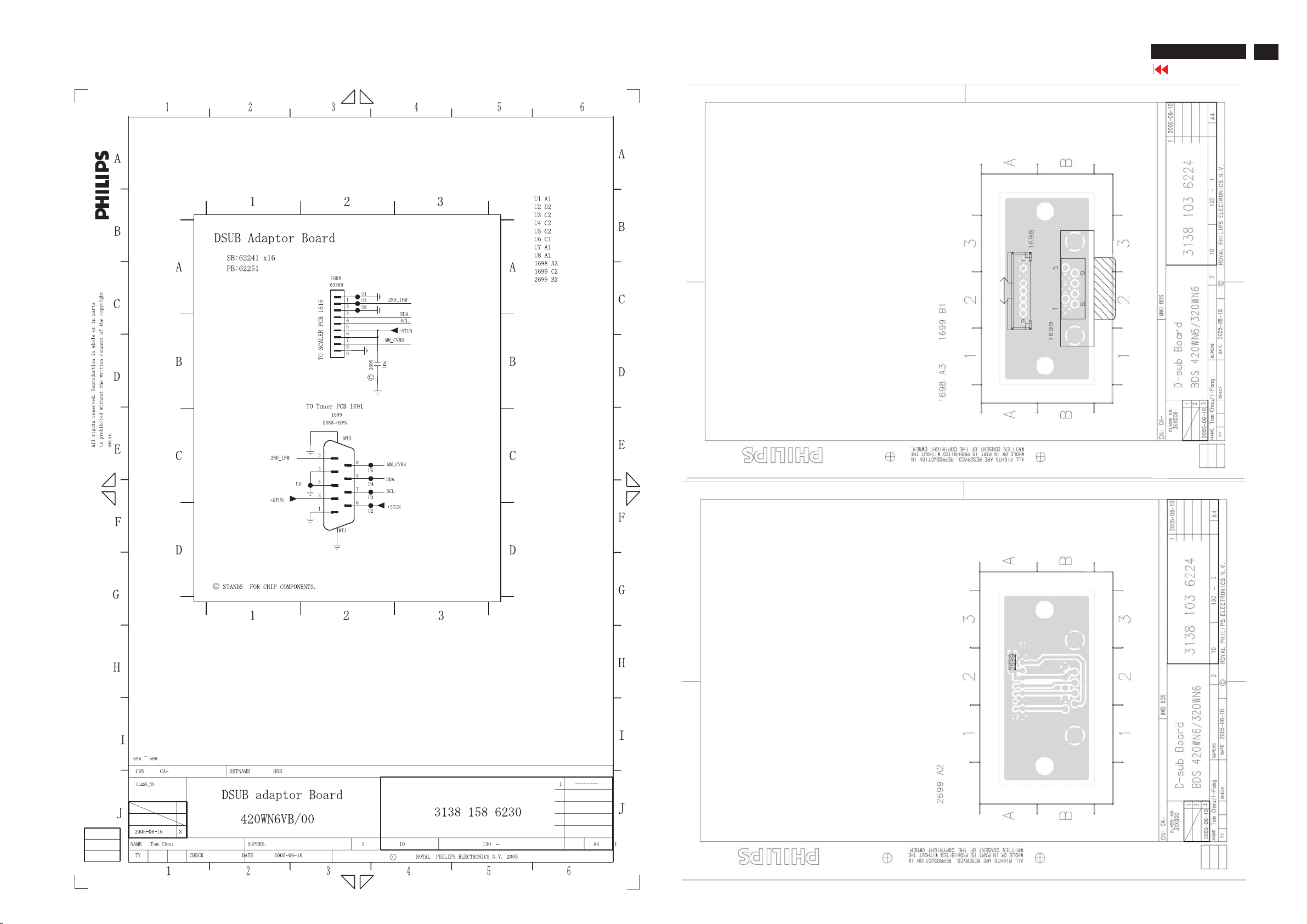
DSUB Diagram&C.B.A
BDL 3221 LCD/TV
Go to cover page
63
Page 64
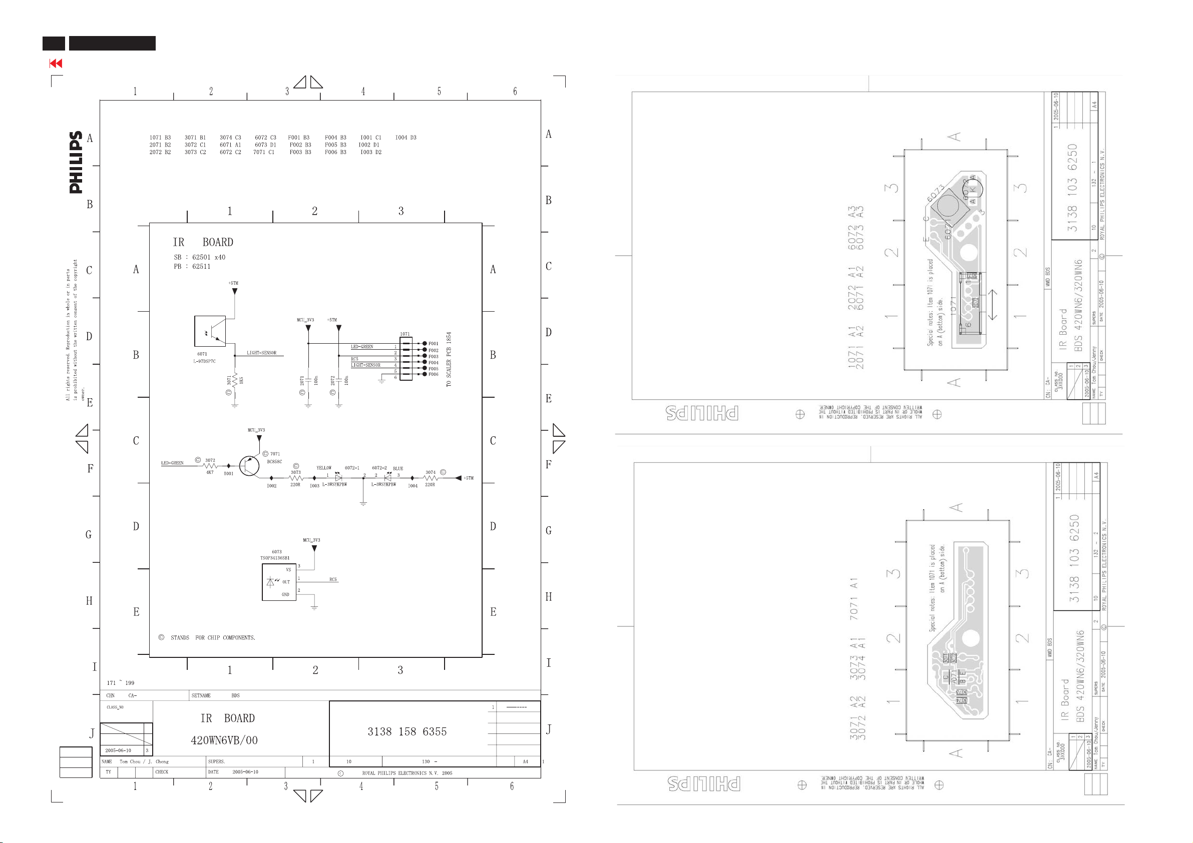
BDL 3221 LCD/TV
64
Go to cover page
IR Diagram&C.B.A
Page 65
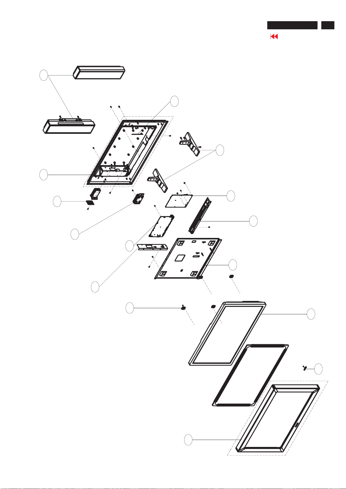
1185
Exploded View
BDL3221 LCD/TV
Go to cover page
65
823827718021
LSP BOX 8R 10W L/R(P302H)
40
313815760441
BACK COVER ASSY
91
313815137571
TV COVER
1053
313815862301
DSUB ADAPOTOR PCB ASSY
1057
313815864721
SCALER ASSY(32-WE)
1055
313815863541
CONTROL PCB ASSY
7
313815760051
BASE ASSY
1058
313815864611
60
POWER PCB ASSY - BDS 32"
94
313815137521
SHIELDING -SCALER BOTTOM
313815137501
BOTTOM MAIN FRAME
313815137511
93
SHIELDING -SCALER RIGHT
95
313815137531
METAL BLOCK-GAP
30
313815760041
FRONT BEZEL ASSY(B)
1050
823827717361
LCD LC320W01-A6K1
1056
313815863551
IR PCB ASSY
Page 66
66
BDL3221 LCD/TV
Go to cover page
Spare Parts List
Model: BDL3221V/00(LPL) 12NC: 8639 000 16304
Mechanical Parts
7 313815760051 BASE ASSY
30 313815760041 FRONT BEZEL ASSY(B)
31 313815161951 FRONT BEZEL
32 313815416701 FRONT CORNER-B/R(BLACK)
33 313815416691 FRONT CORNER-T/R(BLACK)
34 313815410821 LENS
37 313815321431 RUBBER STRIP
38 313815321441 RUBBER-650X15X2
39 313815321451 RUBBER - 360X15X2
40 313815760441 BACK COVER ASSY
41 313815137491 BACK COVER
42 313815410812 CONTROL BOTTON
44 313815416431 HANDLE CLIP
46 313815137431 HANDLE HOLDER
47 313815137421 HANDLE
60 313815137501 BOTTOM MAIN FRAME
91 313815137571 TV COVER
93 313815137511 SHIELDING -SCALER RIGHT
94 313815137521 SHIELDING -SCALER BOTTOM
95 313815137531 METAL BLOCK-GAP
221 313815137381 TV HOUSING
452 313815640741 BOTTOM SLIP BOARD
464 314105631521 SMALL PLASTIC HANDLE
1176 313923811281 PROD ASSY RC1124134/01 PKD
1180 313815864841 MAIN FRAME+WIRE ASSY
Packing Parts
129 313810650281 P.E. BAG (INSTR. BOOK)
455 313815640731 P.E. BAG
456 313815640751 CARTON
457 313815640701 CUSHION-TOP
458 313815640711 CUSHION-BTM
Accessory
145 313811708821 E-D.F.U.(32")
1171 313818871672 MAINSCORD UK 10A 1M8 DET BK
1172 313812874931 MAINSCORD
1173 313819872601 CORD DVI 18+1/1M8/DVI 18+1 B
1175 313819871451 CORD SUB-D 15/1M8/SUB-D 15 B
miscellanea
126 313815567771 RATING LABEL
291 313815567691 LABEL(LG-WE)
292 313815567691 LABEL(LG-WE)
615 313811708611 HEX CODE OF F/W(NO MATL REQ)
1001 242202518823 CON V 10P M 2.00 63390
1051 313819876041 SOC POW H 3P F AC CABL/100
1052 242208600208 FUSE 5X20 HT 4A 250V IEC
1071 242202518818 CON V 6P M 2.00 63386
1071 243803100099 CON V 2P M 2.50 63171
1086 242202518816 CON V 4P M 2.00 63384
1087 242212803035 SWI TACT SM 1P 1POS SKQGAB
1088 242212803035 SWI TACT SM 1P 1POS SKQGAB
1088 242202518904 CON V 12P M 2.50 64842
1089 242212803035 SWI TACT SM 1P 1POS SKQGAB
1089 242202518903 CON V 10P M 2.50 64840
1090 243812800224 SWI PUSH 2P 0.2A 20V SFPC12
1091 242212803035 SWI TACT SM 1P 1POS SKQGAB
1092 242212803035 SWI TACT SM 1P 1POS SKQGAB
1093 242212803035 SWI TACT SM 1P 1POS SKQGAB
1101 242254301364 RES XTL SM 18M432 16P SMD-49
1185 823827718021 LSP BOX 8R 10W L/R(P302H)
1192 823827718601 SPEAKER CABLE 4P (L/R)
1210 242202605769 SOC PHONE H 1P F 3.5 ST BK
1211 242202518432 SOC SUBD H 15P F SBFR
1251 313815859171 DIODE ASSY GBU6J 6051
1252 313815859181 DIODE ASSY STTH5L06 6052
1253 313815859191 DIODE ASSY( 6071,6076)
1254 313815859211 POW TRANS ASSY 7057/ 7062
1255 313815864731 CPU ASSY (LG-WE)
1256 313815864741 EEPROM ASSY (LG-WE)
1301 242203300558 SOC COMBI H 44P F DVI-I/SUBD
1401 243854300086 RES XTL SM 14M318 18P HC49/S
1402 242202518804 CON V 30P M 1.25 SM 60948
1507 242248680958 SOC IC V 52P F 1.77 DIL
1509 243803100435 SOC IC V 8P F 2.54 DIL
1601 313818876611 SOC EURO H 21P F SHE L-GRND
1615 242202518822 CON V 9P M 2.00 63389
1651 242202519075 SOC SUBD H 9P+9P M GN 1297
1698 242202518822 CON V 9P M 2.00 63389
1699 242202518954 SOC SUBD H 9P F BK 1211
1710 242202605803 SOC CINCH H 1P F 1L1 YE
1714 243803100428 SOC CINCH H 2P F 2L1 WHRD
1715 242202605554 SOC CINCH H 8P F 2L4
1719 242202605745 SOC MDIN H 4P F SH 1481-723
1741 243854300089 RES XTL SM 24M576 16P HC49/S
1781 243854300079 RES XTL SM 12MHZ 32P SMD-49
1852 242202518816 CON V 4P M 2.00 63384
1853 242202518819 CON V 7P M 2.00 63387
1854 242202518818 CON V 6P M 2.00 63386
1855 242202518816 CON V 4P M 2.00 63384
1856 242254301508 RES XTL SM 11M059 20P SMD-49
1901 313816877251 EARPHONE JACK
1902 242202518815 CON V 3P M 2.00 63383
1903 242202518814 CON V 2P M 2.00 63382
4444 313810610485 CD ROM - SERVICE MANUAL
4444 313810610486 SERVICE MANUAL
8055 313819876161 CBLE-390 10/160/10-020 AWG26
8152 313819876122 CBLE-019 9/130/9-019 AWG28
8174 313819876151 CBLE-130 30/270/30-033 AWG28
8175 313819876191 CBLE-392 12/620+200/12-022
8177 313819876171 CBLE-014 4/420/4-014 AWG28
8178 313819876181 CBLE-016 6/480/6-016 AWG28
LCD Panel
1050 823827717361 LCD LC320W01-A6K1
PCB A ssy
1053 313815862301 DSUB ADAPOTOR PCB ASSY
1055 313815863541 CONTROL PCB ASSY
1056 313815863551 IR PCB ASSY
1057 313815864721 SCALER ASSY(32-WE)
1058 313815864611 POWER PCB ASSY - BDS 32"
PCB A ssy
1057 313815864721 SCALER ASSY(32-WE)
2002 223858619807 CER2 0603 Y5V 50V 22N P8020
2003 203803513313 ELCAP RGA 25V S 100U PM20
2004 223858619812 CER2 0603 Y5V 50V 100N P8020
2005 223878616641 CER2 0603 X7R 16V 22N PM10
2006 223886715221 CER1 0603 NP0 50V 220P PM5
2007 202203100074 ELCAP KM 16V S 1000U PM20
2008 203803513313 ELCAP RGA 25V S 100U PM20
2009 222224119876 CER2 1206 Y5V 10V 10U P8020
2010 202203100074 ELCAP KM 16V S 1000U PM20
2011 202203100074 ELCAP KM 16V S 1000U PM20
2012 202203100207 ELCAP SM RVS 16V 10U PM20
2013 202203100074 ELCAP KM 16V S 1000U PM20
2014 223858115649 CER2 1206 X7R 50V 100N PM10
2015 203803511407 ELCAP REA 35V S 100U PM20
2016 223886715221 CER1 0603 NP0 50V 220P PM5
2018 223886715221 CER1 0603 NP0 50V 220P PM5
2019 223858619807 CER2 0603 Y5V 50V 22N P8020
2020 223891619849 CER2 0603 Y5V 25V 100N P8020
2021 202202000982 ELCAP GS 35V S 100U PM20
2022 223858115649 CER2 1206 X7R 50V 100N PM10
2023 223858619807 CER2 0603 Y5V 50V 22N P8020
2024 223886715221 CER1 0603 NP0 50V 220P PM5
2025 202203100074 ELCAP KM 16V S 1000U PM20
2101 222224119876 CER2 1206 Y5V 10V 10U P8020
2102 223824619863 CER2 0603 Y5V 10V 1U P8020
2103 223824619863 CER2 0603 Y5V 10V 1U P8020
2104 223824619863 CER2 0603 Y5V 10V 1U P8020
2105 223824619863 CER2 0603 Y5V 10V 1U P8020
2106 223824619863 CER2 0603 Y5V 10V 1U P8020
2107 223824619863 CER2 0603 Y5V 10V 1U P8020
2108 223824619863 CER2 0603 Y5V 10V 1U P8020
2109 223824619863 CER2 0603 Y5V 10V 1U P8020
2110 222224119876 CER2 1206 Y5V 10V 10U P8020
2111 222258015649 CER2 0805 X7R 50V 100N PM10
2112 223886715159 CER1 0603 NP0 50V 15P PM5
2113 223886715479 CER1 0603 NP0 50V 47P PM5
2114 223824619863 CER2 0603 Y5V 10V 1U P8020
2115 223824619863 CER2 0603 Y5V 10V 1U P8020
2116 223824619863 CER2 0603 Y5V 10V 1U P8020
2117 223824619863 CER2 0603 Y5V 10V 1U P8020
2118 223824619863 CER2 0603 Y5V 10V 1U P8020
2119 223824619863 CER2 0603 Y5V 10V 1U P8020
2121 223824619863 CER2 0603 Y5V 10V 1U P8020
2122 223824619863 CER2 0603 Y5V 10V 1U P8020
2123 222258015649 CER2 0805 X7R 50V 100N PM10
2124 222258015649 CER2 0805 X7R 50V 100N PM10
2125 223824615654 CER2 0603 X7R 10V 220N PM10
2126 222224119876 CER2 1206 Y5V 10V 10U P8020
2127 222224119876 CER2 1206 Y5V 10V 10U P8020
2128 222224119876 CER2 1206 Y5V 10V 10U P8020
2129 223878615649 CER2 0603 X7R 16V 100N PM10
2131 222224119876 CER2 1206 Y5V 10V 10U P8020
2132 222224119876 CER2 1206 Y5V 10V 10U P8020
2133 223858615632 CER2 0603 X7R 50V 4N7 PM10
2134 223858615632 CER2 0603 X7R 50V 4N7 PM10
2135 223824619863 CER2 0603 Y5V 10V 1U P8020
2136 223824619863 CER2 0603 Y5V 10V 1U P8020
2137 223824619863 CER2 0603 Y5V 10V 1U P8020
2138 223824619863 CER2 0603 Y5V 10V 1U P8020
2139 222224119876 CER2 1206 Y5V 10V 10U P8020
2141 222258015649 CER2 0805 X7R 50V 100N PM10
2142 222258015649 CER2 0805 X7R 50V 100N PM10
2143 223886715159 CER1 0603 NP0 50V 15P PM5
2144 223886715159 CER1 0603 NP0 50V 15P PM5
2161 223878615649 CER2 0603 X7R 16V 100N PM10
2162 223878615649 CER2 0603 X7R 16V 100N PM10
2163 223878615649 CER2 0603 X7R 16V 100N PM10
2164 223878615649 CER2 0603 X7R 16V 100N PM10
2165 223886715159 CER1 0603 NP0 50V 15P PM5
2166 223878615649 CER2 0603 X7R 16V 100N PM10
2201 222224119876 CER2 1206 Y5V 10V 10U P8020
2202 223886715339 CER1 0603 NP0 50V 33P PM5
2203 223886715109 CER1 0603 NP0 50V 10P PM5
2204 223886715101 CER1 0603 NP0 50V 100P PM5
2205 223886715568 CER1 0603 NP0 50V 5P6 PM0P5
2206 223886715568 CER1 0603 NP0 50V 5P6 PM0P5
2207 223886715568 CER1 0603 NP0 50V 5P6 PM0P5
2208 223878615649 CER2 0603 X7R 16V 100N PM10
2209 223891619849 CER2 0603 Y5V 25V 100N P8020
2211 223886715331 CER1 0603 NP0 50V 330P PM5
2212 223886715331 CER1 0603 NP0 50V 330P PM5
2213 223886715331 CER1 0603 NP0 50V 330P PM5
2214 223886715331 CER1 0603 NP0 50V 330P PM5
2301 223878615649 CER2 0603 X7R 16V 100N PM10
2302 223878615649 CER2 0603 X7R 16V 100N PM10
2401 223878615649 CER2 0603 X7R 16V 100N PM10
2402 223858615636 CER2 0603 X7R 50V 10N PM10
2403 223878615649 CER2 0603 X7R 16V 100N PM10
2404 202002191726 ELCAP SM RVS 16V 47U PM20
2405 222224119876 CER2 1206 Y5V 10V 10U P8020
2406 223878615649 CER2 0603 X7R 16V 100N PM10
2407 223878615649 CER2 0603 X7R 16V 100N PM10
2408 223878615649 CER2 0603 X7R 16V 100N PM10
Page 67

Spare Parts List
BDL3221 LCD/TV
Go to cover page
67
2409 223878615649 CER2 0603 X7R 16V 100N PM10
2410 223878615649 CER2 0603 X7R 16V 100N PM10
2411 223878615649 CER2 0603 X7R 16V 100N PM10
2412 223878615649 CER2 0603 X7R 16V 100N PM10
2413 222224119876 CER2 1206 Y5V 10V 10U P8020
2414 223878615649 CER2 0603 X7R 16V 100N PM10
2415 223878615649 CER2 0603 X7R 16V 100N PM10
2416 223858615636 CER2 0603 X7R 50V 10N PM10
2417 223878615649 CER2 0603 X7R 16V 100N PM10
2418 223878615649 CER2 0603 X7R 16V 100N PM10
2419 223878615645 CER2 0603 X7R 16V 47N PM10
2420 222224119876 CER2 1206 Y5V 10V 10U P8020
2421 223878615649 CER2 0603 X7R 16V 100N PM10
2422 223878615649 CER2 0603 X7R 16V 100N PM10
2423 223878615649 CER2 0603 X7R 16V 100N PM10
2424 223878615649 CER2 0603 X7R 16V 100N PM10
2425 222224119876 CER2 1206 Y5V 10V 10U P8020
2426 223878615649 CER2 0603 X7R 16V 100N PM10
2427 223878615649 CER2 0603 X7R 16V 100N PM10
2428 222224119876 CER2 1206 Y5V 10V 10U P8020
2429 223878615649 CER2 0603 X7R 16V 100N PM10
2430 223878615649 CER2 0603 X7R 16V 100N PM10
2431 223878615645 CER2 0603 X7R 16V 47N PM10
2432 223886715181 CER1 0603 NP0 50V 180P PM5
2433 223858615623 CER2 0603 X7R 50V 1N PM10
2434 223878615645 CER2 0603 X7R 16V 47N PM10
2435 223878615645 CER2 0603 X7R 16V 47N PM10
2436 223858615623 CER2 0603 X7R 50V 1N PM10
2437 223878615645 CER2 0603 X7R 16V 47N PM10
2438 223878615645 CER2 0603 X7R 16V 47N PM10
2439 223878615645 CER2 0603 X7R 16V 47N PM10
2440 223878615645 CER2 0603 X7R 16V 47N PM10
2441 223878615645 CER2 0603 X7R 16V 47N PM10
2442 223878615649 CER2 0603 X7R 16V 100N PM10
2443 202002191726 ELCAP SM RVS 16V 47U PM20
2445 223886715229 CER1 0603 NP0 50V 22P PM5
2446 223886715229 CER1 0603 NP0 50V 22P PM5
2448 223878615649 CER2 0603 X7R 16V 100N PM10
2449 223878615649 CER2 0603 X7R 16V 100N PM10
2450 223878615649 CER2 0603 X7R 16V 100N PM10
2451 222224119876 CER2 1206 Y5V 10V 10U P8020
2452 223878619854 CER2 0603 Y5V 16V 220N P8020
2453 223878615649 CER2 0603 X7R 16V 100N PM10
2471 222224119876 CER2 1206 Y5V 10V 10U P8020
2472 223878615649 CER2 0603 X7R 16V 100N PM10
2473 223878615649 CER2 0603 X7R 16V 100N PM10
2474 223878615649 CER2 0603 X7R 16V 100N PM10
2475 223878615649 CER2 0603 X7R 16V 100N PM10
2476 223878615649 CER2 0603 X7R 16V 100N PM10
2477 222224119876 CER2 1206 Y5V 10V 10U P8020
2478 223878615649 CER2 0603 X7R 16V 100N PM10
2479 223878615649 CER2 0603 X7R 16V 100N PM10
2481 223878615649 CER2 0603 X7R 16V 100N PM10
2482 223878615649 CER2 0603 X7R 16V 100N PM10
2483 223878615649 CER2 0603 X7R 16V 100N PM10
2484 222224119876 CER2 1206 Y5V 10V 10U P8020
2601 223886715471 CER1 0603 NP0 50V 470P PM5
2602 223886715331 CER1 0603 NP0 50V 330P PM5
2603 223886715331 CER1 0603 NP0 50V 330P PM5
2604 223886715471 CER1 0603 NP0 50V 470P PM5
2605 223886715471 CER1 0603 NP0 50V 470P PM5
2606 223886715331 CER1 0603 NP0 50V 330P PM5
2607 223886715331 CER1 0603 NP0 50V 330P PM5
2608 223886715331 CER1 0603 NP0 50V 330P PM5
2609 223886715331 CER1 0603 NP0 50V 330P PM5
2611 223886715331 CER1 0603 NP0 50V 330P PM5
2612 223886715229 CER1 0603 NP0 50V 22P PM5
2613 223886715229 CER1 0603 NP0 50V 22P PM5
2614 223886715229 CER1 0603 NP0 50V 22P PM5
2616 223886715229 CER1 0603 NP0 50V 22P PM5
2618 223878615649 CER2 0603 X7R 16V 100N PM10
2619 223886715331 CER1 0603 NP0 50V 330P PM5
2631 223858619812 CER2 0603 Y5V 50V 100N P8020
2632 223858619812 CER2 0603 Y5V 50V 100N P8020
2633 223858619812 CER2 0603 Y5V 50V 100N P8020
2634 223858619812 CER2 0603 Y5V 50V 100N P8020
2635 222224119876 CER2 1206 Y5V 10V 10U P8020
2636 223858619812 CER2 0603 Y5V 50V 100N P8020
2637 222224119876 CER2 1206 Y5V 10V 10U P8020
2638 223858619812 CER2 0603 Y5V 50V 100N P8020
2639 222224119881 CER2 1206 Y5V 10V 22U P8020
2641 222224119876 CER2 1206 Y5V 10V 10U P8020
2642 222224119876 CER2 1206 Y5V 10V 10U P8020
2643 222224119876 CER2 1206 Y5V 10V 10U P8020
2644 202202001027 ELCAP SM LV 4V 220U PM20
2645 202202001027 ELCAP SM LV 4V 220U PM20
2646 202202001027 ELCAP SM LV 4V 220U PM20
2651 222258015649 CER2 0805 X7R 50V 100N PM10
2652 222224119876 CER2 1206 Y5V 10V 10U P8020
2653 223824619863 CER2 0603 Y5V 10V 1U P8020
2654 223824619863 CER2 0603 Y5V 10V 1U P8020
2655 223824619863 CER2 0603 Y5V 10V 1U P8020
2656 223824619863 CER2 0603 Y5V 10V 1U P8020
2657 223824619863 CER2 0603 Y5V 10V 1U P8020
2677 222224119876 CER2 1206 Y5V 10V 10U P8020
2678 202203100074 ELCAP KM 16V S 1000U PM20
2679 223886715229 CER1 0603 NP0 50V 22P PM5
2701 223886715331 CER1 0603 NP0 50V 330P PM5
2702 223886715331 CER1 0603 NP0 50V 330P PM5
2703 223886715331 CER1 0603 NP0 50V 330P PM5
2704 223886715331 CER1 0603 NP0 50V 330P PM5
2705 223886715331 CER1 0603 NP0 50V 330P PM5
2706 223886715331 CER1 0603 NP0 50V 330P PM5
2707 223886715331 CER1 0603 NP0 50V 330P PM5
2708 223886715331 CER1 0603 NP0 50V 330P PM5
2709 223886715331 CER1 0603 NP0 50V 330P PM5
2711 223886715331 CER1 0603 NP0 50V 330P PM5
2713 223886715331 CER1 0603 NP0 50V 330P PM5
2715 223886715331 CER1 0603 NP0 50V 330P PM5
2742 223878616641 CER2 0603 X7R 16V 22N PM10
2743 223878616641 CER2 0603 X7R 16V 22N PM10
2744 223878616641 CER2 0603 X7R 16V 22N PM10
2746 223878616641 CER2 0603 X7R 16V 22N PM10
2747 223878616641 CER2 0603 X7R 16V 22N PM10
2748 223878616641 CER2 0603 X7R 16V 22N PM10
2749 223878616641 CER2 0603 X7R 16V 22N PM10
2751 223878616641 CER2 0603 X7R 16V 22N PM10
2753 223878616641 CER2 0603 X7R 16V 22N PM10
2754 223878616641 CER2 0603 X7R 16V 22N PM10
2755 223878616641 CER2 0603 X7R 16V 22N PM10
2756 223878616641 CER2 0603 X7R 16V 22N PM10
2757 223878615649 CER2 0603 X7R 16V 100N PM10
2758 223878615649 CER2 0603 X7R 16V 100N PM10
2759 222224119876 CER2 1206 Y5V 10V 10U P8020
2761 223878615649 CER2 0603 X7R 16V 100N PM10
2762 223878615649 CER2 0603 X7R 16V 100N PM10
2763 223878615649 CER2 0603 X7R 16V 100N PM10
2764 223878615649 CER2 0603 X7R 16V 100N PM10
2765 223878615649 CER2 0603 X7R 16V 100N PM10
2766 223878615649 CER2 0603 X7R 16V 100N PM10
2767 223878615649 CER2 0603 X7R 16V 100N PM10
2768 223878615649 CER2 0603 X7R 16V 100N PM10
2769 223878615649 CER2 0603 X7R 16V 100N PM10
2771 223878615649 CER2 0603 X7R 16V 100N PM10
2772 223886715279 CER1 0603 NP0 50V 27P PM5
2773 223886715279 CER1 0603 NP0 50V 27P PM5
2774 202002191726 ELCAP SM RVS 16V 47U PM20
2775 202002191726 ELCAP SM RVS 16V 47U PM20
2776 223878615649 CER2 0603 X7R 16V 100N PM10
2781 222224119876 CER2 1206 Y5V 10V 10U P8020
2782 223878615649 CER2 0603 X7R 16V 100N PM10
2783 223878615649 CER2 0603 X7R 16V 100N PM10
2784 222224119876 CER2 1206 Y5V 10V 10U P8020
2785 222224119876 CER2 1206 Y5V 10V 10U P8020
2786 223886715159 CER1 0603 NP0 50V 15P PM5
2787 223886715159 CER1 0603 NP0 50V 15P PM5
2788 222224119876 CER2 1206 Y5V 10V 10U P8020
2789 222224119876 CER2 1206 Y5V 10V 10U P8020
2791 223886715109 CER1 0603 NP0 50V 10P PM5
2792 223886715109 CER1 0603 NP0 50V 10P PM5
2793 223886715109 CER1 0603 NP0 50V 10P PM5
2801 223878615649 CER2 0603 X7R 16V 100N PM10
2802 223878615649 CER2 0603 X7R 16V 100N PM10
2803 223878615649 CER2 0603 X7R 16V 100N PM10
2804 223878615649 CER2 0603 X7R 16V 100N PM10
2805 223878615649 CER2 0603 X7R 16V 100N PM10
2806 223878615649 CER2 0603 X7R 16V 100N PM10
2807 223878615649 CER2 0603 X7R 16V 100N PM10
2808 223878615649 CER2 0603 X7R 16V 100N PM10
2809 223878615649 CER2 0603 X7R 16V 100N PM10
2811 223878615649 CER2 0603 X7R 16V 100N PM10
2812 223878615649 CER2 0603 X7R 16V 100N PM10
2813 223878615649 CER2 0603 X7R 16V 100N PM10
2814 223878615649 CER2 0603 X7R 16V 100N PM10
2815 223878615649 CER2 0603 X7R 16V 100N PM10
2816 223878615649 CER2 0603 X7R 16V 100N PM10
2817 223878615649 CER2 0603 X7R 16V 100N PM10
2818 223878615649 CER2 0603 X7R 16V 100N PM10
2819 223878615649 CER2 0603 X7R 16V 100N PM10
2821 223878615649 CER2 0603 X7R 16V 100N PM10
2822 223878615649 CER2 0603 X7R 16V 100N PM10
2823 223878615649 CER2 0603 X7R 16V 100N PM10
2824 223878615649 CER2 0603 X7R 16V 100N PM10
2825 223878615649 CER2 0603 X7R 16V 100N PM10
2826 223886715339 CER1 0603 NP0 50V 33P PM5
2827 223878615649 CER2 0603 X7R 16V 100N PM10
2851 223878615649 CER2 0603 X7R 16V 100N PM10
2852 223878615649 CER2 0603 X7R 16V 100N PM10
2853 222224119876 CER2 1206 Y5V 10V 10U P8020
2854 223886715229 CER1 0603 NP0 50V 22P PM5
2855 223886715229 CER1 0603 NP0 50V 22P PM5
2856 223858615623 CER2 0603 X7R 50V 1N PM10
2857 222224119876 CER2 1206 Y5V 10V 10U P8020
2858 223886715109 CER1 0603 NP0 50V 10P PM5
2859 223858615636 CER2 0603 X7R 50V 10N PM10
2861 223858615636 CER2 0603 X7R 50V 10N PM10
2865 223878615649 CER2 0603 X7R 16V 100N PM10
2866 223886715101 CER1 0603 NP0 50V 100P PM5
2867 223886715101 CER1 0603 NP0 50V 100P PM5
2868 223858615636 CER2 0603 X7R 50V 10N PM10
2869 223858015636 CER2 0805 X7R 50V 10N PM10
2871 223858615636 CER2 0603 X7R 50V 10N PM10
2872 223858615636 CER2 0603 X7R 50V 10N PM10
2873 202002191726 ELCAP SM RVS 16V 47U PM20
2901 202203100132 ELCAP LZ 25V S 1000U PM20
2902 223891015649 CER2 0805 X7R 25V 100N PM10
2903 202203100132 ELCAP LZ 25V S 1000U PM20
2904 203803511203 ELCAP REA 16V S 100U PM20
2905 223858615636 CER2 0603 X7R 50V 10N PM10
2906 223858615636 CER2 0603 X7R 50V 10N PM10
2907 203803511203 ELCAP REA 16V S 100U PM20
2908 223886715101 CER1 0603 NP0 50V 100P PM5
2909 223824619863 CER2 0603 Y5V 10V 1U P8020
2911 223878615649 CER2 0603 X7R 16V 100N PM10
2912 222224119876 CER2 1206 Y5V 10V 10U P8020
2913 222224119876 CER2 1206 Y5V 10V 10U P8020
2914 223886715101 CER1 0603 NP0 50V 100P PM5
2915 223824619863 CER2 0603 Y5V 10V 1U P8020
2916 223891619849 CER2 0603 Y5V 25V 100N P8020
2917 223891619849 CER2 0603 Y5V 25V 100N P8020
2918 223891619849 CER2 0603 Y5V 25V 100N P8020
2919 223891619849 CER2 0603 Y5V 25V 100N P8020
2923 202203100182 ELCAP SM RVS 25V 10U PM20
2924 223886715221 CER1 0603 NP0 50V 220P PM5
2925 223878619854 CER2 0603 Y5V 16V 220N P8020
2926 223878619854 CER2 0603 Y5V 16V 220N P8020
2928 223878619854 CER2 0603 Y5V 16V 220N P8020
2929 223878619854 CER2 0603 Y5V 16V 220N P8020
2932 223878619854 CER2 0603 Y5V 16V 220N P8020
Page 68
68
BDL3221 LCD/TV
Go to cover page
Spare Parts List
2933 202203100182 ELCAP SM RVS 25V 10U PM20
2934 223891619849 CER2 0603 Y5V 25V 100N P8020
2935 223891619849 CER2 0603 Y5V 25V 100N P8020
2936 223891619849 CER2 0603 Y5V 25V 100N P8020
2937 223891619849 CER2 0603 Y5V 25V 100N P8020
2938 202203100182 ELCAP SM RVS 25V 10U PM20
2939 223891619849 CER2 0603 Y5V 25V 100N P8020
2941 223878615649 CER2 0603 X7R 16V 100N PM10
2942 223858119716 CER2 1206 Y5V 50V 470N PM20
2943 223878619854 CER2 0603 Y5V 16V 220N P8020
2944 223886715101 CER1 0603 NP0 50V 100P PM5
2945 223878615649 CER2 0603 X7R 16V 100N PM10
2946 223886715101 CER1 0603 NP0 50V 100P PM5
2947 223878619854 CER2 0603 Y5V 16V 220N P8020
2948 223878615649 CER2 0603 X7R 16V 100N PM10
2949 223878615649 CER2 0603 X7R 16V 100N PM10
2951 223886715101 CER1 0603 NP0 50V 100P PM5
2952 223886715101 CER1 0603 NP0 50V 100P PM5
2953 223858119716 CER2 1206 Y5V 50V 470N PM20
2954 202203100231 ELCAP SM HV 50V 1U PM20
2955 202203100231 ELCAP SM HV 50V 1U PM20
2956 223878619854 CER2 0603 Y5V 16V 220N P8020
2957 223878619854 CER2 0603 Y5V 16V 220N P8020
3001 232270260473 RST SM 0603 RC21 47K PM5
3002 212211805682 RST SM 0603 RC0603 82K PM5
3004 232270260101 RST SM 0603 RC21 100R PM5
3005 232270260473 RST SM 0603 RC21 47K PM5
3006 212211805669 RST SM 0603 RC0603 10K PM5
3007 232270260472 RST SM 0603 RC21 4K7 PM5
3008 232270463303 RST SM 0603 RC22H 33K PM1
3009 212211805676 RST SM 0603 RC0603 33K PM5
3010 212211805667 RST SM 0603 RC0603 6K8 PM5
3011 232270260472 RST SM 0603 RC21 4K7 PM5
3012 232270463002 RST SM 0603 RC22H 3K PM1
3013 232270461003 RST SM 0603 RC22H 10K PM1
3014 213810500082 RST MOX 1W RSS S 0R82 PM5
3015 232270461001 RST SM 0603 RC22H 100R PM1
3016 232270463902 RST SM 0603 RC22H 3K9 PM1
3017 232270260223 RST SM 0603 RC21 22K PM5
3018 232270260473 RST SM 0603 RC21 47K PM5
3019 212211805669 RST SM 0603 RC0603 10K PM5
3022 232270260101 RST SM 0603 RC21 100R PM5
3024 232270260101 RST SM 0603 RC21 100R PM5
3031 232270260472 RST SM 0603 RC21 4K7 PM5
3034 232270461002 RST SM 0603 RC22H 1K PM1
3035 232270260472 RST SM 0603 RC21 4K7 PM5
3036 232270462001 RST SM 0603 RC22H 200R PM1
3041 232270260101 RST SM 0603 RC21 100R PM5
3042 232270463302 RST SM 0603 RC22H 3K3 PM1
3043 232270463902 RST SM 0603 RC22H 3K9 PM1
3044 232270465602 RST SM 0603 RC22H 5K6 PM1
3045 232270463303 RST SM 0603 RC22H 33K PM1
3101 232270260222 RST SM 0603 RC21 2K2 PM5
3102 212211805687 RST SM 0603 RC0603 470K PM5
3103 212211805687 RST SM 0603 RC0603 470K PM5
3104 212211805687 RST SM 0603 RC0603 470K PM5
3105 212211805687 RST SM 0603 RC0603 470K PM5
3106 212211805687 RST SM 0603 RC0603 470K PM5
3107 212211805687 RST SM 0603 RC0603 470K PM5
3108 212211805687 RST SM 0603 RC0603 470K PM5
3109 212211805687 RST SM 0603 RC0603 470K PM5
3110 232270260222 RST SM 0603 RC21 2K2 PM5
3111 212211805669 RST SM 0603 RC0603 10K PM5
3112 212211805669 RST SM 0603 RC0603 10K PM5
3113 232270260101 RST SM 0603 RC21 100R PM5
3114 232270260101 RST SM 0603 RC21 100R PM5
3115 232270260273 RST SM 0603 RC21 27K PM5
3116 232270260101 RST SM 0603 RC21 100R PM5
3117 232270260101 RST SM 0603 RC21 100R PM5
3118 232270260101 RST SM 0603 RC21 100R PM5
3119 232270260101 RST SM 0603 RC21 100R PM5
3121 232270260101 RST SM 0603 RC21 100R PM5
3122 232270260101 RST SM 0603 RC21 100R PM5
3123 232270260101 RST SM 0603 RC21 100R PM5
3124 232270260101 RST SM 0603 RC21 100R PM5
3161 232270260471 RST SM 0603 RC21 470R PM5
3162 232270260473 RST SM 0603 RC21 47K PM5
3201 232270260472 RST SM 0603 RC21 4K7 PM5
3202 232270260101 RST SM 0603 RC21 100R PM5
3203 232270260101 RST SM 0603 RC21 100R PM5
3204 232270260472 RST SM 0603 RC21 4K7 PM5
3205 232270260101 RST SM 0603 RC21 100R PM5
3206 232270260472 RST SM 0603 RC21 4K7 PM5
3207 232270260472 RST SM 0603 RC21 4K7 PM5
3208 232270260101 RST SM 0603 RC21 100R PM5
3209 212211805642 RST SM 0603 RC0603 75R PM5
3211 232270260689 RST SM 0603 RC21 68R PM5
3212 232270260101 RST SM 0603 RC21 100R PM5
3213 212211805642 RST SM 0603 RC0603 75R PM5
3214 232270260689 RST SM 0603 RC21 68R PM5
3215 232270260101 RST SM 0603 RC21 100R PM5
3216 212211805642 RST SM 0603 RC0603 75R PM5
3217 232270260689 RST SM 0603 RC21 68R PM5
3218 232270260101 RST SM 0603 RC21 100R PM5
3219 232270260101 RST SM 0603 RC21 100R PM5
3221 232270260102 RST SM 0603 RC21 1K PM5
3222 232270260273 RST SM 0603 RC21 27K PM5
3223 232270260102 RST SM 0603 RC21 1K PM5
3224 232270260273 RST SM 0603 RC21 27K PM5
3225 232270260472 RST SM 0603 RC21 4K7 PM5
3301 232270260102 RST SM 0603 RC21 1K PM5
3302 232270260101 RST SM 0603 RC21 100R PM5
3303 232270260101 RST SM 0603 RC21 100R PM5
3304 232270260101 RST SM 0603 RC21 100R PM5
3305 232270260472 RST SM 0603 RC21 4K7 PM5
3306 232270260472 RST SM 0603 RC21 4K7 PM5
3307 232270260472 RST SM 0603 RC21 4K7 PM5
3401 213810500082 RST MOX 1W RSS S 0R82 PM5
3402 232270260101 RST SM 0603 RC21 100R PM5
3403 212211805651 RST SM 0603 RC0603 390R PM5
3404 232270260471 RST SM 0603 RC21 470R PM5
3405 232270260471 RST SM 0603 RC21 470R PM5
3406 212211805635 RST SM 0603 RC0603 10R PM5
3407 212211805635 RST SM 0603 RC0603 10R PM5
3408 212211805635 RST SM 0603 RC0603 10R PM5
3409 212211805635 RST SM 0603 RC0603 10R PM5
3410 212211805635 RST SM 0603 RC0603 10R PM5
3411 212211805635 RST SM 0603 RC0603 10R PM5
3412 212211805635 RST SM 0603 RC0603 10R PM5
3413 212211805635 RST SM 0603 RC0603 10R PM5
3414 235003510101 RST NETW SM ARV24 4X100R PM5
3415 235003510229 RST NETW SM ARV24 4X 22R PM5
3416 235003510229 RST NETW SM ARV24 4X 22R PM5
3417 235003510229 RST NETW SM ARV24 4X 22R PM5
3418 235003510229 RST NETW SM ARV24 4X 22R PM5
3419 235003510229 RST NETW SM ARV24 4X 22R PM5
3420 235003510229 RST NETW SM ARV24 4X 22R PM5
3421 235003510229 RST NETW SM ARV24 4X 22R PM5
3422 235003510229 RST NETW SM ARV24 4X 22R PM5
3423 235003510229 RST NETW SM ARV24 4X 22R PM5
3424 232270461002 RST SM 0603 RC22H 1K PM1
3425 232270461002 RST SM 0603 RC22H 1K PM1
3427 232270260102 RST SM 0603 RC21 1K PM5
3428 232270260689 RST SM 0603 RC21 68R PM5
3429 232270260689 RST SM 0603 RC21 68R PM5
3430 232270260689 RST SM 0603 RC21 68R PM5
3471 232270260339 RST SM 0603 RC21 33R PM5
3472 232270260339 RST SM 0603 RC21 33R PM5
3473 232270260339 RST SM 0603 RC21 33R PM5
3474 232270260339 RST SM 0603 RC21 33R PM5
3475 212211805645 RST SM 0603 RC0603 150R PM5
3476 212211805637 RST SM 0603 RC0603 22R PM5
3477 212211805637 RST SM 0603 RC0603 22R PM5
3478 212211805637 RST SM 0603 RC0603 22R PM5
3479 212211805637 RST SM 0603 RC0603 22R PM5
3601 212211805645 RST SM 0603 RC0603 150R PM5
3602 232270260101 RST SM 0603 RC21 100R PM5
3603 232270260224 RST SM 0603 RC21 220K PM5
3604 232270260102 RST SM 0603 RC21 1K PM5
3605 232270260273 RST SM 0603 RC21 27K PM5
3606 232270260101 RST SM 0603 RC21 100R PM5
3607 232270260224 RST SM 0603 RC21 220K PM5
3608 232270260102 RST SM 0603 RC21 1K PM5
3609 232270260273 RST SM 0603 RC21 27K PM5
3611 212211805642 RST SM 0603 RC0603 75R PM5
3612 232270260243 RST SM 0603 RC21 24K PM5
3613 212211805642 RST SM 0603 RC0603 75R PM5
3614 212211805642 RST SM 0603 RC0603 75R PM5
3615 232270260102 RST SM 0603 RC21 1K PM5
3616 232270260102 RST SM 0603 RC21 1K PM5
3617 232270260689 RST SM 0603 RC21 68R PM5
3618 232270260102 RST SM 0603 RC21 1K PM5
3619 232270462709 RST SM 0603 RC22H 27R PM1
3621 212211805639 RST SM 0603 RC0603 47R PM5
3622 232270260101 RST SM 0603 RC21 100R PM5
3623 232270260101 RST SM 0603 RC21 100R PM5
3624 232270260101 RST SM 0603 RC21 100R PM5
3625 232270260102 RST SM 0603 RC21 1K PM5
3626 232270260102 RST SM 0603 RC21 1K PM5
3627 232270260473 RST SM 0603 RC21 47K PM5
3628 232270260473 RST SM 0603 RC21 47K PM5
3629 232270260473 RST SM 0603 RC21 47K PM5
3631 212211805667 RST SM 0603 RC0603 6K8 PM5
3634 212211805642 RST SM 0603 RC0603 75R PM5
3635 212211805642 RST SM 0603 RC0603 75R PM5
3636 212211805642 RST SM 0603 RC0603 75R PM5
3637 232270461002 RST SM 0603 RC22H 1K PM1
3638 232270461002 RST SM 0603 RC22H 1K PM1
3651 212211805976 RST SM 0603 RC0603 3K PM5
3652 232270461002 RST SM 0603 RC22H 1K PM1
3653 212211805669 RST SM 0603 RC0603 10K PM5
3654 212211805669 RST SM 0603 RC0603 10K PM5
3679 213810500082 RST MOX 1W RSS S 0R82 PM5
3681 232270260472 RST SM 0603 RC21 4K7 PM5
3682 212211805635 RST SM 0603 RC0603 10R PM5
3683 232270260101 RST SM 0603 RC21 100R PM5
3684 232270260472 RST SM 0603 RC21 4K7 PM5
3685 232270260102 RST SM 0603 RC21 1K PM5
3686 213811201111 RST SM 0805 RC05 110R PM5
3687 212211805639 RST SM 0603 RC0603 47R PM5
3701 212211805639 RST SM 0603 RC0603 47R PM5
3702 232270260279 RST SM 0603 RC21 27R PM5
3703 232270260279 RST SM 0603 RC21 27R PM5
3704 212211805639 RST SM 0603 RC0603 47R PM5
3705 232270260102 RST SM 0603 RC21 1K PM5
3706 232270260279 RST SM 0603 RC21 27R PM5
3707 212211805642 RST SM 0603 RC0603 75R PM5
3708 212211805639 RST SM 0603 RC0603 47R PM5
3709 212211805642 RST SM 0603 RC0603 75R PM5
3710 212211805642 RST SM 0603 RC0603 75R PM5
3711 232270260102 RST SM 0603 RC21 1K PM5
3712 232270260273 RST SM 0603 RC21 27K PM5
3714 232270260102 RST SM 0603 RC21 1K PM5
3715 232270260273 RST SM 0603 RC21 27K PM5
3718 212211805642 RST SM 0603 RC0603 75R PM5
3721 232270260101 RST SM 0603 RC21 100R PM5
3723 232270260101 RST SM 0603 RC21 100R PM5
3724 232270260224 RST SM 0603 RC21 220K PM5
3725 232270260224 RST SM 0603 RC21 220K PM5
3727 232270260102 RST SM 0603 RC21 1K PM5
3728 232270260102 RST SM 0603 RC21 1K PM5
3729 232270260273 RST SM 0603 RC21 27K PM5
3730 232270260273 RST SM 0603 RC21 27K PM5
3741 212211805639 RST SM 0603 RC0603 47R PM5
3742 212211805639 RST SM 0603 RC0603 47R PM5
3743 212211805639 RST SM 0603 RC0603 47R PM5
3744 232270260681 RST SM 0603 RC21 680R PM5
3745 232270260511 RST SM 0603 RC21 510R PM5
Page 69
Spare Parts List
BDL3221 LCD/TV
Go to cover page
69
3746 212211805639 RST SM 0603 RC0603 47R PM5
3747 232270260332 RST SM 0603 RC21 3K3 PM5
3748 212211805639 RST SM 0603 RC0603 47R PM5
3749 232270260101 RST SM 0603 RC21 100R PM5
3751 232270260101 RST SM 0603 RC21 100R PM5
3752 232270260472 RST SM 0603 RC21 4K7 PM5
3753 232270260472 RST SM 0603 RC21 4K7 PM5
3754 232270260472 RST SM 0603 RC21 4K7 PM5
3755 232270260101 RST SM 0603 RC21 100R PM5
3756 232270260101 RST SM 0603 RC21 100R PM5
3757 235003510101 RST NETW SM ARV24 4X100R PM5
3758 235003510101 RST NETW SM ARV24 4X100R PM5
3781 232270260472 RST SM 0603 RC21 4K7 PM5
3782 232270260472 RST SM 0603 RC21 4K7 PM5
3783 212261200066 NTC DC TTC-103 S 10K PM5
3784 232270260102 RST SM 0603 RC21 1K PM5
3785 212211805642 RST SM 0603 RC0603 75R PM5
3786 232270260243 RST SM 0603 RC21 24K PM5
3787 232270260472 RST SM 0603 RC21 4K7 PM5
3788 232270260472 RST SM 0603 RC21 4K7 PM5
3789 232270260101 RST SM 0603 RC21 100R PM5
3791 232270260101 RST SM 0603 RC21 100R PM5
3792 212211805645 RST SM 0603 RC0603 150R PM5
3793 212211805645 RST SM 0603 RC0603 150R PM5
3794 212211805645 RST SM 0603 RC0603 150R PM5
3795 212211805659 RST SM 0603 RC0603 1K8 PM5
3796 212211805659 RST SM 0603 RC0603 1K8 PM5
3797 212211805659 RST SM 0603 RC0603 1K8 PM5
3801 212211805635 RST SM 0603 RC0603 10R PM5
3802 232270260472 RST SM 0603 RC21 4K7 PM5
3804 232270260101 RST SM 0603 RC21 100R PM5
3806 232270260101 RST SM 0603 RC21 100R PM5
3807 232270260101 RST SM 0603 RC21 100R PM5
3808 232270260472 RST SM 0603 RC21 4K7 PM5
3811 235003510689 RST NETW SM ARV24 4X 68R PM5
3812 235003510689 RST NETW SM ARV24 4X 68R PM5
3813 235003510689 RST NETW SM ARV24 4X 68R PM5
3814 235003510689 RST NETW SM ARV24 4X 68R PM5
3815 235003510229 RST NETW SM ARV24 4X 22R PM5
3816 235003510229 RST NETW SM ARV24 4X 22R PM5
3852 232270461005 RST SM 0603 RC22H 1M PM1
3853 232270260101 RST SM 0603 RC21 100R PM5
3854 232270260332 RST SM 0603 RC21 3K3 PM5
3855 232270260472 RST SM 0603 RC21 4K7 PM5
3856 232270260472 RST SM 0603 RC21 4K7 PM5
3857 232270260332 RST SM 0603 RC21 3K3 PM5
3858 232270260101 RST SM 0603 RC21 100R PM5
3859 232270260472 RST SM 0603 RC21 4K7 PM5
3860 232270260332 RST SM 0603 RC21 3K3 PM5
3862 232270260472 RST SM 0603 RC21 4K7 PM5
3865 232270260472 RST SM 0603 RC21 4K7 PM5
3867 232270260473 RST SM 0603 RC21 47K PM5
3869 232270260473 RST SM 0603 RC21 47K PM5
3872 232270260472 RST SM 0603 RC21 4K7 PM5
3873 232270260332 RST SM 0603 RC21 3K3 PM5
3874 232270260332 RST SM 0603 RC21 3K3 PM5
3875 232270260101 RST SM 0603 RC21 100R PM5
3884 212211805647 RST SM 0603 RC0603 220R PM5
3885 212211805647 RST SM 0603 RC0603 220R PM5
3886 212211805647 RST SM 0603 RC0603 220R PM5
3887 212211805647 RST SM 0603 RC0603 220R PM5
3888 232270260332 RST SM 0603 RC21 3K3 PM5
3889 232270260332 RST SM 0603 RC21 3K3 PM5
3891 232270260101 RST SM 0603 RC21 100R PM5
3892 232270260471 RST SM 0603 RC21 470R PM5
3893 232270260101 RST SM 0603 RC21 100R PM5
3901 212211805669 RST SM 0603 RC0603 10K PM5
3902 232270260223 RST SM 0603 RC21 22K PM5
3903 212211805669 RST SM 0603 RC0603 10K PM5
3904 232270260223 RST SM 0603 RC21 22K PM5
3905 232270260223 RST SM 0603 RC21 22K PM5
3906 232270260332 RST SM 0603 RC21 3K3 PM5
3907 232270260223 RST SM 0603 RC21 22K PM5
3908 232270260332 RST SM 0603 RC21 3K3 PM5
3909 212211805639 RST SM 0603 RC0603 47R PM5
3911 212211805944 RST SM 0603 RC0603 120K PM5
3912 212211805667 RST SM 0603 RC0603 6K8 PM5
3914 212211805667 RST SM 0603 RC0603 6K8 PM5
3915 232270260472 RST SM 0603 RC21 4K7 PM5
4101 232270296001 RST SM 0603 JUMP. MAX 0R05
4102 232270296001 RST SM 0603 JUMP. MAX 0R05
4103 232270296001 RST SM 0603 JUMP. MAX 0R05
4104 232270296001 RST SM 0603 JUMP. MAX 0R05
4105 232270296001 RST SM 0603 JUMP. MAX 0R05
4161 232270296001 RST SM 0603 JUMP. MAX 0R05
4162 232270296001 RST SM 0603 JUMP. MAX 0R05
4163 232270296001 RST SM 0603 JUMP. MAX 0R05
4164 232270296001 RST SM 0603 JUMP. MAX 0R05
4168 232270296001 RST SM 0603 JUMP. MAX 0R05
4174 232270296001 RST SM 0603 JUMP. MAX 0R05
4402 232270296001 RST SM 0603 JUMP. MAX 0R05
4601 232270296001 RST SM 0603 JUMP. MAX 0R05
4652 232270296001 RST SM 0603 JUMP. MAX 0R05
4654 232270296001 RST SM 0603 JUMP. MAX 0R05
4657 232270296001 RST SM 0603 JUMP. MAX 0R05
4659 232270296001 RST SM 0603 JUMP. MAX 0R05
4701 232270296001 RST SM 0603 JUMP. MAX 0R05
4702 232270296001 RST SM 0603 JUMP. MAX 0R05
4703 232270296001 RST SM 0603 JUMP. MAX 0R05
4801 232270296001 RST SM 0603 JUMP. MAX 0R05
4804 232270296001 RST SM 0603 JUMP. MAX 0R05
4805 232270296001 RST SM 0603 JUMP. MAX 0R05
4811 232270296001 RST SM 0603 JUMP. MAX 0R05
4812 232270296001 RST SM 0603 JUMP. MAX 0R05
4813 232270296001 RST SM 0603 JUMP. MAX 0R05
4814 232270296001 RST SM 0603 JUMP. MAX 0R05
4815 232270296001 RST SM 0603 JUMP. MAX 0R05
4851 232270296001 RST SM 0603 JUMP. MAX 0R05
4854 232270296001 RST SM 0603 JUMP. MAX 0R05
4855 232270296001 RST SM 0603 JUMP. MAX 0R05
4856 235003591001 RST NETW SM ARV24 4X JUMPER
4857 232270296001 RST SM 0603 JUMP. MAX 0R05
4858 232270296001 RST SM 0603 JUMP. MAX 0R05
4901 232270296001 RST SM 0603 JUMP. MAX 0R05
4903 232270296001 RST SM 0603 JUMP. MAX 0R05
5001 313818875771 COI CHOKE 35UH 82M OHM DR10X
5003 313818875771 COI CHOKE 35UH 82M OHM DR10X
5004 242254945579 IND FXD 1206 EMI 100MHZ 100R
5005 313818875771 COI CHOKE 35UH 82M OHM DR10X
5006 313818875771 COI CHOKE 35UH 82M OHM DR10X
5007 242254945579 IND FXD 1206 EMI 100MHZ 100R
5101 242253595853 IND FXD SM 0603 0U10 PM10
5102 242253595853 IND FXD SM 0603 0U10 PM10
5161 242254945579 IND FXD 1206 EMI 100MHZ 100R
5201 242254900449 IND FXD 0805 EMI 100MHZ 200R
5202 242254900449 IND FXD 0805 EMI 100MHZ 200R
5203 242254900449 IND FXD 0805 EMI 100MHZ 200R
5401 242254944197 IND FXD 0805 EMI 100MHZ 220R
5402 242254944197 IND FXD 0805 EMI 100MHZ 220R
5403 242254944197 IND FXD 0805 EMI 100MHZ 220R
5404 242254944197 IND FXD 0805 EMI 100MHZ 220R
5405 242254944197 IND FXD 0805 EMI 100MHZ 220R
5406 242254944197 IND FXD 0805 EMI 100MHZ 220R
5407 242254944197 IND FXD 0805 EMI 100MHZ 220R
5408 242254944197 IND FXD 0805 EMI 100MHZ 220R
5409 242254944197 IND FXD 0805 EMI 100MHZ 220R
5410 242254944197 IND FXD 0805 EMI 100MHZ 220R
5471 242254900449 IND FXD 0805 EMI 100MHZ 200R
5601 242253595853 IND FXD SM 0603 0U10 PM10
5602 242253595853 IND FXD SM 0603 0U10 PM10
5603 242253595853 IND FXD SM 0603 0U10 PM10
5604 242253595853 IND FXD SM 0603 0U10 PM10
5605 242253595853 IND FXD SM 0603 0U10 PM10
5607 242254900442 IND FXD 0603 EMI 100MHZ 600R
5701 242253595853 IND FXD SM 0603 0U10 PM10
5702 242253595853 IND FXD SM 0603 0U10 PM10
5704 242253595853 IND FXD SM 0603 0U10 PM10
5705 242253595853 IND FXD SM 0603 0U10 PM10
5706 242253595853 IND FXD SM 0603 0U10 PM10
5707 242253595853 IND FXD SM 0603 0U10 PM10
5741 242254900449 IND FXD 0805 EMI 100MHZ 200R
5742 242254900442 IND FXD 0603 EMI 100MHZ 600R
5743 242254900442 IND FXD 0603 EMI 100MHZ 600R
5744 242254900442 IND FXD 0603 EMI 100MHZ 600R
5745 242254900442 IND FXD 0603 EMI 100MHZ 600R
5746 242254900442 IND FXD 0603 EMI 100MHZ 600R
5781 242254944197 IND FXD 0805 EMI 100MHZ 220R
5782 242253595853 IND FXD SM 0603 0U10 PM10
5783 242253595853 IND FXD SM 0603 0U10 PM10
5784 242253595853 IND FXD SM 0603 0U10 PM10
5801 242254944197 IND FXD 0805 EMI 100MHZ 220R
5802 242254944197 IND FXD 0805 EMI 100MHZ 220R
5803 242254944197 IND FXD 0805 EMI 100MHZ 220R
5804 242254944197 IND FXD 0805 EMI 100MHZ 220R
5851 242254944197 IND FXD 0805 EMI 100MHZ 220R
5852 242254944197 IND FXD 0805 EMI 100MHZ 220R
5901 242254900126 IND FXD 0805 EMI 100MHZ 120R
5903 243853598058 IND FXD BEAD EMI 100MHZ 80R
5904 242253595853 IND FXD SM 0603 0U10 PM10
5905 242253595853 IND FXD SM 0603 0U10 PM10
5906 242253600782 IND FXD TSL0808 S 33U PM10
5907 242254900126 IND FXD 0805 EMI 100MHZ 120R
5908 242254900126 IND FXD 0805 EMI 100MHZ 120R
5909 242253600782 IND FXD TSL0808 S 33U PM10
5911 242254900126 IND FXD 0805 EMI 100MHZ 120R
5912 242254900126 IND FXD 0805 EMI 100MHZ 120R
5913 242253600782 IND FXD TSL0808 S 33U PM10
5914 242253600782 IND FXD TSL0808 S 33U PM10
5915 242254900126 IND FXD 0805 EMI 100MHZ 120R
6001 932221745685 DIO REC SM SSA34-E3 (VISH)
6003 932208282668 DIO REC SM SS34-E3 (VISH)
6004 932221745685 DIO REC SM SSA34-E3 (VISH)
6005 932221745685 DIO REC SM SSA34-E3 (VISH)
6007 933913910115 DIO SIG SM BAS32L (PHSE)
6101 933913910115 DIO SIG SM BAS32L (PHSE)
6202 933913910115 DIO SIG SM BAS32L (PHSE)
6203 933913910115 DIO SIG SM BAS32L (PHSE)
6301 933913910115 DIO SIG SM BAS32L (PHSE)
6302 933913910115 DIO SIG SM BAS32L (PHSE)
6701 932205042685 DIO SIG SM BAV99LG (ONSE)
7001 932211529668 FET POW SM SI9433DY-E3 (VISH
7002 932219076668 IC SM L5972D (ST00)
7004 932219076668 IC SM L5972D (ST00)
7005 932218295668 IC SM LD1117S (ST00)
7006 932213067676 IC L78L08ACZ (ST00)
7007 933967270685 TRA SIG SM BC847CLG (ONSE)
7008 933967270685 TRA SIG SM BC847CLG (ONSE)
7010 932219076668 IC SM L5972D (ST00)
7012 932219076668 IC SM L5972D (ST00)
7013 932217440685 TRA SIG SM KRC102S (KEC0)
7016 932217440685 TRA SIG SM KRC102S (KEC0)
7101 932217440685 TRA SIG SM KRC102S (KEC0)
7102 932217440685 TRA SIG SM KRC102S (KEC0)
7103 932217891668 IC SM M74HC4052RM (ST00)
7104 823827718301 AUDIO-DECORDER MSP3450G
7161 932219513668 IC SM M74HC590M (ST00)
7162 932215366668 IC SM CY7C199-15ZC (CYPR)
7163 932219513668 IC SM M74HC590M (ST00)
7164 935187000118 IC SM 74HC573PW (PHSE)
7165 933828890215 TRA SIG SM PMBT2369 (PHSE)
7166 935187000118 IC SM 74HC573PW (PHSE)
7201 935245720165 IC SM 74HCT1G14GW (PHSE)
7202 932214526668 IC SM M24C02-WMN6 (ST00)
7301 932214526668 IC SM M24C02-WMN6 (ST00)
7401 932222077668 IC SM AME1117ECGTZ (AME0)
7402 932222076668 IC SM AME1117CCGTZ (AME0)
Page 70
70
BDL3221 LCD/TV
Go to cover page
Spare Parts List
7403 932222593671 IC SM MST5151A-LF (MSTA)
7404 932222075668 IC SM AME1117BCGTZ (AME0)
7471 823827716361 MEMORY IC
7601 933967270685 TRA SIG SM BC847CLG (ONSE)
7602 932220138668 IC SM AD8187ARU (ANA0)
7605 935260739118 IC SM 74LVC14APW (PHSE)
7651 932220869668 IC SM DS14C232CM (NSC0)
7653 932218295668 IC SM LD1117S (ST00)
7654 932217440685 TRA SIG SM KRC102S (KEC0)
7655 932217440685 TRA SIG SM KRC102S (KEC0)
7676 933967310685 TRA SIG SM BC848CLG (ONSE)
7701 933967270685 TRA SIG SM BC847CLG (ONSE)
7741 935276561518 IC SM SAA7119E/V2/G (PHSE)
7742 932222076668 IC SM AME1117CCGTZ (AME0)
7743 932222077668 IC SM AME1117ECGTZ (AME0)
7781 935275732112 IC SAA5264PS/M3/1437 (PHSE)
7782 933967310685 TRA SIG SM BC848CLG (ONSE)
7801 932220476671 IC SM T6TU5XBG-0001(O2)
7802 823827716781 1M16-42S16100A1
7852 932219183685 IC SM LM809M3-2.93 NOPB(NSC0
7853 933967270685 TRA SIG SM BC847CLG (ONSE)
7855 932222010682 IC SM NT68F632ALG (NOVA)
7858 932212209682 IC M24C32-WBN6P (ST00)
7901 935273874115 IC SM TDA1308T/N2 (PHSE)
7902 932222037668 IC SM TPA3008D2PHP (TI00)
PCB A ssy
1058 313815864611 POWER PCB ASSY - BDS 32"
2051 202233000078 CAP MPP 275V S 470N PM10
2052 202055490156 CERSAF CD 250V S 1N PM20
2053 202055490156 CERSAF CD 250V S 1N PM20
2054 202233000078 CAP MPP 275V S 470N PM10
2055 823827718501 1.5MF 450V MPP
2056 222291019856 CER2 0805 Y5V 25V 330N P8020
2057 222224119876 CER2 1206 Y5V 10V 10U P8020
2058 223858015636 CER2 0805 X7R 50V 10N PM10
2059 223891015649 CER2 0805 X7R 25V 100N PM10
2060 202203100426 ELCAP HS 450V S 120U PM20
2061 202055790153 CER2 DC B 500V S 2N2 PM10
2062 242254900673 SURGE PROTECT SPG-201M-A
2063 242254900673 SURGE PROTECT SPG-201M-A
2064 242254900673 SURGE PROTECT SPG-201M-A
2065 223858015643 CER2 0805 X7R 50V 33N PM10
2066 203803521302 ELCAP GS 25V S 4U7 PM20
2067 203803521307 ELCAP GS 25V S 68U PM20
2068 202203100272 ELCAP PF 25V S 47U PM20
2069 242254900673 SURGE PROTECT SPG-201M-A
2070 223891015649 CER2 0805 X7R 25V 100N PM10
2071 202055490158 CERSAF CD 250V S 2N2 PM20
2072 223858015627 CER2 0805 X7R 50V 2N2 PM10
2073 203830150151 CAP PP PPN 100V S 10N PM2
2074 202203100387 ELCAP EB 25V S 2200U PM20
2075 202203100273 ELCAP PF 25V S 100U PM20
2076 223858015649 CER2 0805 X7R 50V 100N PM10
2077 203830150191 CAP PP PPN 100V S 3N3 PM2
2078 203830150159 CAP PP PPN 100V S 12N PM5
2079 202203100428 ELCAP GF 35V S 1000U PM20
2080 202203100428 ELCAP GF 35V S 1000U PM20
2081 203803527502 ELCAP KM 50V S 22U PM20
2085 223858015625 CER2 0805 X7R 50V 1N5 PM10
2086 202202000805 ELCAP GS 50V S 2U2 PM20
2087 223858015636 CER2 0805 X7R 50V 10N PM10
2088 223891015649 CER2 0805 X7R 25V 100N PM10
2091 223891015649 CER2 0805 X7R 25V 100N PM10
2092 223891015649 CER2 0805 X7R 25V 100N PM10
3051 212211805971 RST SM 1206 RC1206 270K PM5
3052 212211805971 RST SM 1206 RC1206 270K PM5
3053 212211805971 RST SM 1206 RC1206 270K PM5
3054 232271161824 RST SM 1206 RC01 820K PM5
3055 232271161824 RST SM 1206 RC01 820K PM5
3056 213811201822 RST SM 0805 RC05 8K2 PM5
3057 232273061333 RST SM 0805 RC11 33K PM5
3058 212210101515 RST CRB CF1/6 A 390R PM5
3059 212010500027 RST MOX 1W RSS A 0R15 PM1
3060 232271161333 RST SM 1206 RC01 33K PM5
3061 213810113228 RST CRB CFR-12 A 2R2 PM5
3062 232273061689 RST SM 0805 RC11 68R PM5
3063 232271161108 RST SM 1206 RC01 1R PM5
3064 232273463304 RST SM 0805 RC12H 330K PM1
3065 232273463304 RST SM 0805 RC12H 330K PM1
3066 232273463304 RST SM 0805 RC12H 330K PM1
3067 232273466201 RST SM 0805 RC12H 620R PM1
3068 232273465602 RST SM 0805 RC12H 5K6 PM1
3069 212255000184 VDR DC 1MA/510V S MAX 845V
3070 232273061102 RST SM 0805 RC11 1K PM5
3071 212261200074 NTC DC SCK-034 S 3R PM15
3072 823827718171 VDR DC 1MA/510 845V R
3073 213811201105 RST SM 0805 RC05 1M PM5
3074 213811201224 RST SM 0805 RC05 220K PM5
3075 232273061102 RST SM 0805 RC11 1K PM5
3076 232273061471 RST SM 0805 RC11 470R PM5
3077 232273061274 RST SM 0805 RC11 270K PM5
3078 232273061474 RST SM 0805 RC11 470K PM5
3079 213811201331 RST SM 0805 RC05 330R PM5
3080 213811201103 RST SM 0805 RC05 10K PM5
3081 212010500027 RST MOX 1W RSS A 0R15 PM1
3082 213811201151 RST SM 0805 RC05 150R PM5
3083 213810113228 RST CRB CFR-12 A 2R2 PM5
3084 213811201222 RST SM 0805 RC05 2K2 PM5
3085 232273061102 RST SM 0805 RC11 1K PM5
3086 213811201152 RST SM 0805 RC05 1K5 PM5
3087 213810113334 RST CRB CFR-12 A 330K PM5
3088 232273061229 RST SM 0805 RC11 22R PM5
3089 213811201222 RST SM 0805 RC05 2K2 PM5
3090 232273461002 RST SM 0805 RC12H 1K PM1
3091 232273461803 RST SM 0805 RC12H 18K PM1
3092 213811201101 RST SM 0805 RC05 100R PM5
3093 212210102197 RST CRB CF1/6 A 4K7 PM5
3094 232273061223 RST SM 0805 RC11 22K PM5
3095 232273462202 RST SM 0805 RC12H 2K2 PM1
3096 232273061223 RST SM 0805 RC11 22K PM5
3097 232273061223 RST SM 0805 RC11 22K PM5
3098 213811201103 RST SM 0805 RC05 10K PM5
5051 242254900499 FIL MAINS 6MH 1A8 S42010
5052 243853598026 IND FXD BEAD EMI 100MHZ 35R
5053 243853598026 IND FXD BEAD EMI 100MHZ 35R
5054 242254900498 FIL MAINS 5MH 2A S4103
5055 242254900497 FIL PFC 430UH 0R19 S4084
5056 313816875411 BEAD
5057 313816875411 BEAD
5058 243853598026 IND FXD BEAD EMI 100MHZ 35R
5059 313816875411 BEAD
5060 313816875411 BEAD
5061 242253597072 IND FXD SP0305 A 6U8 PM10
5071 242254900503 TFM SMT LAYER HJC-S4143 WIRE
5072 243853598026 IND FXD BEAD EMI 100MHZ 35R
5073 243853598026 IND FXD BEAD EMI 100MHZ 35R
5074 242253601187 IND FXD OL1028H S 15U PM10
5075 243853598026 IND FXD BEAD EMI 100MHZ 35R
5076 243853598026 IND FXD BEAD EMI 100MHZ 35R
5077 243853598026 IND FXD BEAD EMI 100MHZ 35R
5078 243853598026 IND FXD BEAD EMI 100MHZ 35R
5079 242253601102 IND FXD OL1028H S 10U PM10
5080 242253601187 IND FXD OL1028H S 15U PM10
6051 931900263671 BRIDGE GBU6J-E3 (VISH)
6052 932220958687 DIO REC STTH5L06FP (ST00)
6053 933952580685 DIO SIG SM BAV103 (VISH)
6055 932214069673 DIO SUP P6KE250A A (VISH)
6056 932222163673 DIO REC UF1007 A (LITO)
6061 933952580685 DIO SIG SM BAV103 (VISH)
6062 933952580685 DIO SIG SM BAV103 (VISH)
6063 933952580685 DIO SIG SM BAV103 (VISH)
6064 933751660673 DIO REC RGP10D-E3 A (VISH)
6065 933952580685 DIO SIG SM BAV103 (VISH)
6066 933751660673 DIO REC RGP10D-E3 A (VISH)
6067 932222228673 DIO SUP P4KE16A-E3 (VISH)
6071 932219932687 DIO REC STPS10H100CFP (ST00)
6072 933952580685 DIO SIG SM BAV103 (VISH)
6073 933952580685 DIO SIG SM BAV103 (VISH)
6074 933117810133 DIO REG BZX79-C12 A (PHSE)
6075 933712760673 DIO REG BZX55-B18 A (VISH)
6076 932219203687 DIO REC STPS20H100CFP (ST00)
6081 933712970673 DIO REG BZX55-C20 A (VISH)
7056 932222284682 IC L6562N (ST00)
7057 932217923687 FET POW STP20NM60 (ST00)
7061 935267356112 IC TEA1507P/N1 (PHSE)
7062 932219657687 FET POW STP10NK80ZFP (ST00)
7063 933953410676 TRA SIG TBC328-40 (TOSJ)
7071 932217439685 TRA SIG SM BC857C (KEC0)
7072 932214014667 OPT CP TCET1103(G) (VISH)
7073 932208697676 IC TL431ACZ S (ST00)
7074 932214014667 OPT CP TCET1103(G) (VISH)
7075 933705890676 TRA SIG BF422 (TOSJ)
7076 933237790126 TRA SIG BC547C (PHSE)
PCB A ssy
1053 313815862301 DSUB ADAPOTOR PCB ASSY
2699 222224119876 CER2 1206 Y5V 10V 10U P8020
PCB A ssy
1055 313815863541 CONTROL PCB ASSY
2091 223858615636 CER2 0603 X7R 50V 10N PM10
2093 223858619805 CER2 0603 Y5V 50V 10N P8020
2094 223858619805 CER2 0603 Y5V 50V 10N P8020
3086 232270260101 RST SM 0603 RC21 100R PM5
3087 232270260512 RST SM 0603 RC21 5K1 PM5
3088 212211805662 RST SM 0603 RC0603 2K7 PM5
3089 232270260122 RST SM 0603 RC21 1K2 PM5
3091 212211805669 RST SM 0603 RC0603 10K PM5
PCB A ssy
1056 313815863551 IR PCB ASSY
2071 223858619812 CER2 0603 Y5V 50V 100N P8020
2072 223858619812 CER2 0603 Y5V 50V 100N P8020
3071 232270260152 RST SM 0603 RC21 1K5 PM5
3072 232270260472 RST SM 0603 RC21 4K7 PM5
3073 212211805647 RST SM 0603 RC0603 220R PM5
3074 212211805647 RST SM 0603 RC0603 220R PM5
6071 932219711682 OPT SEN L-97DSP7C (KIEL)
6072 932219382682 LED VS L-3WSYKPBW (KIEL)
6073 932220313667 IR RECEIVER TSOP34136SB1
Page 71

Recommended Parts List
Recommended Parts List
TYPE:BDL3221V/00
7 313815760051 BASE ASSY
30 313815760041 FRONT BEZEL ASSY(B)
31 313815161951 FRONT BEZEL
32 313815416701 FRONT CORNER-B/R(BLACK)
33 313815416691 FRONT CORNER-T/R(BLACK)
34 313815410821 LENS
37 313815321431 RUBBER STRIP
38 313815321441 RUBBER-650X15X2
39 313815321451 RUBBER - 360X15X2
40 313815760441 BACK COVER ASSY
41 313815137491 BACK COVER
42 313815410812 CONTROL BOTTON
44 313815416431 HANDLE CLIP
46 313815137431 HANDLE HOLDER
47 313815137421 HANDLE
60 313815137501 BOTTOM MAIN FRAME
91 313815137571 TV COVER
93 313815137511 SHIELDING -SCALER RIGHT
94 313815137521 SHIELDING -SCALER BOTTOM
95 313815137531 METAL BLOCK-GAP
126 313815567771 RATING LABEL
145 313811708821 E-D.F.U.(32")
221 313815137381 TV HOUSING
291 313815567691 LABEL(LG-WE)
292 313815567691 LABEL(LG-WE)
452 313815640741 BOTTOM SLIP BOARD
455 313815640731 P.E. BAG
456 313815640751 CARTON
457 313815640701 CUSHION-TOP
458 313815640711 CUSHION-BTM
464 314105631521 SMALL PLASTIC HANDLE
615 313811708611 HEX CODE OF F/W(NO MATL REQ)
1176 313923811281 PROD ASSY RC1124134/01 PKD
7001 932211529668 FET POW SM SI9433DY-E3 (VISH
7002 932219076668 IC SM L5972D (ST00)
7007 933967270685 TRA SIG SM BC847CLG (ONSE)
7013 932217440685 TRA SIG SM KRC102S (KEC0)
7056 932222284682 IC L6562N (ST00)
7057 932217923687 FET POW STP20NM60 (ST00)
7072 932214014667 OPT CP TCET1103(G) (VISH)
7073 932208697676 IC TL431ACZ S (ST00)
7074 932214014667 OPT CP TCET1103(G) (VISH)
7162 932215366668 IC SM CY7C199-15ZC (CYPR)
7202 932214526668 IC SM M24C02-WMN6 (ST00)
7403 932222593671 IC SM MST5151A-LF (MSTA)
7676 933967310685 TRA SIG SM BC848CLG (ONSE)
7743 932222077668 IC SM AME1117ECGTZ (AME0)
7801 932220476671 IC SM T6TU5XBG-0001(O2)
7802 823827716781 1M16-42S16100A1
7852 932219183685 IC SM LM809M3-2.93 NOPB(NSC0
7855 932222010682 IC SM NT68F632ALG (NOVA)
7902 932222037668 IC SM TPA3008D2PHP (TI00)
8055 313819876161 CBLE-390 10/160/10-020 AWG26
8152 313819876122 CBLE-019 9/130/9-019 AWG28
8174 313819876151 CBLE-130 30/270/30-033 AWG28
8175 313819876191 CBLE-392 12/620+200/12-022
8177 313819876171 CBLE-014 4/420/4-014 AWG28
8178 313819876181 CBLE-016 6/480/6-016 AWG28
BDL3221 LCD/TV
Go to cover page
71
Page 72
BDL3221 LCD/TV
72
Go to cover page
GENERAL PRODUCT SPECIFICATION
GENERAL PRODUCT SPECIFICATION
. 32" Multifunction LCD monitor
. PC 15 pins D-SUB analog interface
. PC audio line in with mini-Jack
. TV Tuner, S-Video, RCA AV input/output interface with R/L Audio-in
.SCARTinterface
. DVI digital interface with HDCP support (for TV and PC)
. HD/Component YPbPr with L/R audio input (RCA connector)
. NTSC, PAL,SECAM TV color system
. PC graphic auto picture adjustment
. 12 user modes
. User-friendly OSD menu
. User-friendly remote controller
. Recommend r esolution 1366 x 768 non-interlace at 60 Hz
. WXGA 32" color TFT LCD flat panel
. Anti-glare to reduc e light reflection
. Power management capability
. VESA standard wall mount kit (option)
2005-06-17
Freud Yu
32 inch BDS WXGA TFT LCD Monitor/TV
TYPE : BDL3221V/00
BRAND : PHILIPS
32
2005-06-17
8639 000 16304
590
1
Page 73
GENERAL PRODUCT SPECIFICATION(Continued)
CONTENTS
1.0 Foreword
2.0 Product profile
2.1 LCD
2.2 Scanningfrequencies
2.3 Video dot rate
2.4 Power input
2.5 Power consumption
2.6 Dimensions
2.7 Weight
2.8 Side speaker
2.9 Functions
2.10 Ambient temperature
2.11 Regulatory compliance
3.0 Electrical characteristics
3.1 Interface signals cables
3.2 User interface
3.2.1 Frontand rear control panel
3.2.2 Frontand rear control panel definition
3.2.3 Remote control
3.2.4 OSDMenu
3.2.5 RS232 control
3.3 PC, TV requirement
3.3.1 PC interface
3.3.1.1 Modestoring capacity
3.3.1.2 Horizontal scanning
3.3.1.3 Vertical scanning
3.3.1.4 Inputconnectors
3.3.1.5 Available timings
3.3.2 I/Ointerface
3.3.3 TV
3.3.3.1 TV Tuner
3.3.3.2 Deviation of TV system
3.3.3.3 TV color setting
3.3.3.4 TV audiosetting
3.3.3.5 TV special setting
3.3.4 Electric characteristics of I/O
3.3.4.1 PC Signal type
3.3.4.2 TV Signal type
3.3.4.3 CVBS output
3.3.4.4 Headphoneoutput
3.3.5 Picture in picture
3.3.5.1 Display function
3.3.5.2 Display size
3.3.5.3 Display location
3.3.5.4 Picture by pi
3.3.5.5 Zoom
3.4 Pow er inputconnection
3.5 Pow er management
interface
cture
BDL3221 LCD/TV
Go to cover page
73
4.0 Vis ual ch aracteristi cs
4.1 Test conditions
4.2 PCresolution
4.3 Brightness
4.4 Image size
4.4.1 Actual display size
4.5 Brightness uniformity
4.6 PCwhite color adjustment
32 inch BDS WXGA TFT LCD Monitor/TV
TYPE : BDL3221V/00
BRAND:PHILIPS
2005-06-17
Freud Yu
2005-06-17
32
8639 000 16304
590
2
Page 74
BDL3221 LCD/TV
74
Go to cover page
5.0 Mechanical characteristics
6.0 Environm en t al ch ar ac t er ist i c s
7.0 Reliability
8.0 Quality assurance requirements
GENERAL PRODUCT SPECIFICATION(Continued)
4.7 TV white color adjustment
4.8 TV picture centering
4.9 HD support timing
4.9.1 HD detail timing
5.1 Controls
5.2 Unit dimension / weight
5.3 Tilt and swivel base
5.4 Transportation packages
5.4.1 Shipping dimension / weight
5.4.2 Block unit / palletization
6.1 Susceptibility of display to external environment
6.2 Transportation tests
6.3 Display disturbances from external environment
7.1 Mean time between failures
8.1 Acceptance test
9.0 Serviceability
10.0 Appendices
·
Fig 1
Pattern 1 - Brightness and Uniformity
Pattern 2 - Cross talk patt ern - Gray leave 184 (256 gray level)
Pattern 3 - Cross talk pattern - Center gray lev el 0 (Black)
·
Table 1
·
Table 2
·
Table 3
·
Table 4
WE model:
NAFTA model:
AP model:
China model:
West Europe TV Preload channels
US - Air broadcast channels
US - Cable channels
AP multi TV preload channels
China TV preload channels
2005-06-17
Freud Yu
32 inch BDS WXGA TFT LCD Monitor/TV
TYPE : BDL3221V/00
BRAND : PHILIPS
32
2005-06-17
8639 000 16304
590
3
Page 75
GENERAL PRODUCT SPECIFICATION(Continued)
1.0 FOREWORD
This specificationdescribes a 32" multifunction LCD Monitor, maximumresolutionup to 1366x768/60Hz non-interlaced.
2.0 PRODUCT PROFILE
This32"TFTLCDmonitor/TV can connect to PC'sanalog D-SUBand TV's digital signal through DVI-D connector and it
also have TV, Composite Video, S-Video, S
2.1 LCD
2.1.1 L PLpan el
Type NO : LC320W01 A6K3 (Supplier LPL)
Display area(mm) : 697.685mm x 392.256mm
Number of Pixels : 1366(H) x768(V)
Pitch ( mm ) : 0.170mm(H) x0.510mum(V)
Color pixel arrangement:RGB vertical stripe
Display operatingmode:Normally black
Color depth : 16,7M colors ( 8bits)
Bright
Viewingangle(CR>10) :Viewingangle free(R/L 178(Typ.),U/D 178(Typ.))
Surface treatment:Hard coating(3H),Anti-glare treatmentofthefrontpolarize
Electrical interface : LVDS
Response Time (ms, Ty p) :TrR:8,TrD:10(Gray to Gray)
Contrast ratio:Typical 1000 : 1 with AI
Outl
Module weight (g) :7,200g(Typ.)
Backlight : 20 EEFL
ness (cd/m^2) :500(Center 1 points, Typ.)
ineDimension :760mm(H) x450mm(V) x48(D) mm (Typ.)
cart , PVR outputand HD YPbPr interface.
BDL3221 LCD/TV
Go to cover page
75
2.2 Scanningfrequencies : Hor. : 45 - 50KHz Ver.: 47 - 63 H z
2.3 Video dot rate : <80 MHz
2.4 Power input : 90 - 264 Vac, 50/60 ± 2Hz
2.5 Power consumption :100W/Typ.( at PCmode ) ,130W/Typ.( at TV mode ).
2.6 UnitDimensi
Speaker dimensions : 110mmWx490mmHx 70mmD
2.7 UnitWeight : 19.17 kg (exclude speaker boxs , Incl. Pedestal)
2.8 Speakers & unitweight : 2 x 10 W (weight : 2.8 kg)
2.9 Funct i ons :
PC
TV
ons : 794 mm W x 517 mm H x 244 mm D (Incl. Pedestal, excl. speaker)
·
15 pinsD-subanalog interface with audiomini-Jack input (PCline in).
·
15 pinsD-subanalog output
·
DVI-D Digital interface (support TV DVI HDCPinput)
·
DVI-D Digital interface (Support HDCP) share with PCaudio input.
·
Tuner, Aerial input.
·
HD/ComponentYPbPr inputand audio inputwith RCA jack.
·
Composite video inputand S-Video inputsharewith the same audio.
·
Scart connector support RGB/S-video/ CVBSinputand tuner CVBS output.
·
PVR output (Composite Video and Audiooutput).
·
Headphoneoutput.
2005-06-17
Freud Yu
32 inch BDS WXGA TFT LCD Monitor/TV
TYPE : BDL3221V/00
BRAND:PHILIPS
32
2005-06-17
8639 000 16304
590
4
Page 76
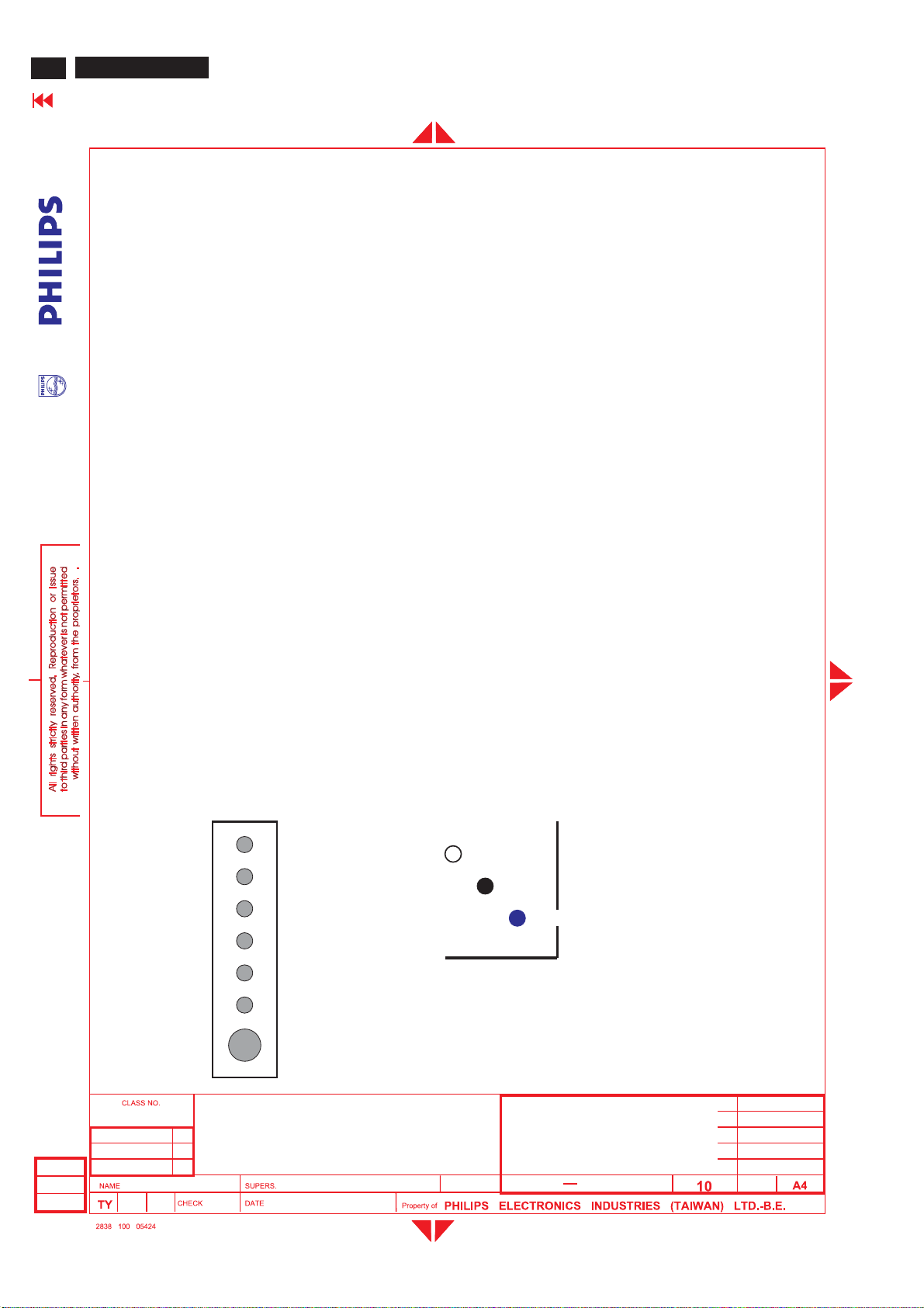
BDL3221 LCD/TV
76
Go to cover page
2.10 A mbi en t t emperat :
2.11 Regulat ory compliance :
3.0 Electrical characteristics
3.1 Interface s i gnals cabl es
GENERAL PRODUCT SPECIFICATION(Continued)
0-40°C
Safety requirement: CCC (China), CSA(Canada), IEC 950 CB Report, SEMKO(Nordic), UL(USA), PSB(Singapore)
EMI requirement: C-tick, CE (Europe), FCC (USA), IC (Canada)
VGA Interface Cable
Length : 1.8 M +/- 50 mm
DVI-D Cable
Length : 1.8 M +/- 50 mm
Stereo RCA R/L audio cable (option)
Length : 1.5 M +/- 50 mm
S-video cable (option)
Length : 1.5 M +/- 50 mm
AV cable (option)
Length : 1.5M +/- 50 mm
SCART cable (option)
Length : 1.5 M +/- 50 mm
Mini Jack stereo cable (option)
Length : 1.5 M +/- 50 mm
YPbPr c able (option)
Length : 1.5M +/- 50mm
Power cord
Length : 1.8 M +/- 50 mm
3.2 Us er in terface
On screen display user control via rear keypad and remote control for PC and TV OSD.
3.2.1 Front and Rear control panel
Rear Control Panel
Input select
Down / Channel -
UP / Channel +
Left/ Volume -
Right / Volume+
OSD
Front Control Panel
Light Sensor
IR receiver
Power LED
2005-06-17
Freud Yu
DC Power Switch
32 inch BDS WXGA TFT LCD Monitor/TV
TYPE : BDL3221V/00
BRAND : PHILIPS
32
2005-06-17
8639 000 16304
590
5
Page 77
GENERAL PRODUCT SPECIFICATION(Continued)
3.2.2 Fron tand Rear control panel def inition:
Front
Power LED:Normal operationàBlue.
Standby modeàAmber.
IR receiver : Sense the signal from RChandset.
Light Sensor : Itwill set the LCD back light brightness automatically accordingtothe
ambientlight.
Rear
BDL3221 LCD/TV
Go to cover page
77
Inputselect : Inputso
Up/Down :Channel upand down,and OSDcursor upand down.
Left/Right : Volume upand down,and OSDcursor left and right.
OSD:Enable OSDmenu(Enter key for PC).
Power SW:DCPower switch.
Power SW:AC Power switch.
3.2.3 Remot e c ontrol
3.2.3.1 The remote control is usedinall PCand TV modes :
I. BeaMonitor:
1. Press Menu Key to call Monitor Menu
2. Press Up/D own/Left/Right Key to select Monitor function
3. Left/Right isVolume Hot Key.
4. Use remote controller to select PCmenu function.
II.BeaTV:
1. Press Menu Key to display TV Menu
2. Press Up/D own/Left/Right Key to select TV function
3. Up/Down Key isCha
4. Left/Right Key isVolume Hot Key.
5. Use remote controller to select TV menu function.
III. Recall ingfromsavingmod e:
urce select key
PC à DVIà HDCP à TVàAVà S-VIDEO àEXTàHD and PCagain.
nnel Hot Key.
In Monitor power savingmode, which noH&Vsync, or noeither H-syncorV-sync inputviaVGA
connector. The monitor will enter "Monitor savingmode".
The way to wake upMonitor
1. whenPCH-syncand V-synchavesignal again ,then Monitor wi
2. press "Source" key on remote controlà change to Video source directly.
In TV power savingmod e, which switched off by RC"Standby" key, SLEEP TIMER function or noTVsignal input for 30
minutes, the monitor will enter "TV standby mode", and LED shows amber color.
The way to wake upMonitor
1. press . "Standby" key on remote control to return orig
2. press "Source" key on remote controlà change to other Video source directly.
Remark :
1. When TV is in savingmode (Amber LED), P ow er off by rear DC power switch key .
2. When DC re-power on,thesetwill still stay in savingmode(as previousmode)
inal Video source
ll wake up.
32 inch BDS WXGA TFT LCD Monitor/TV
2005-06-17
Freud Yu
TYPE : BDL3221V/00
BRAND:PHILIPS
32
2005-06-17
8639 000 16304
590
6
Page 78
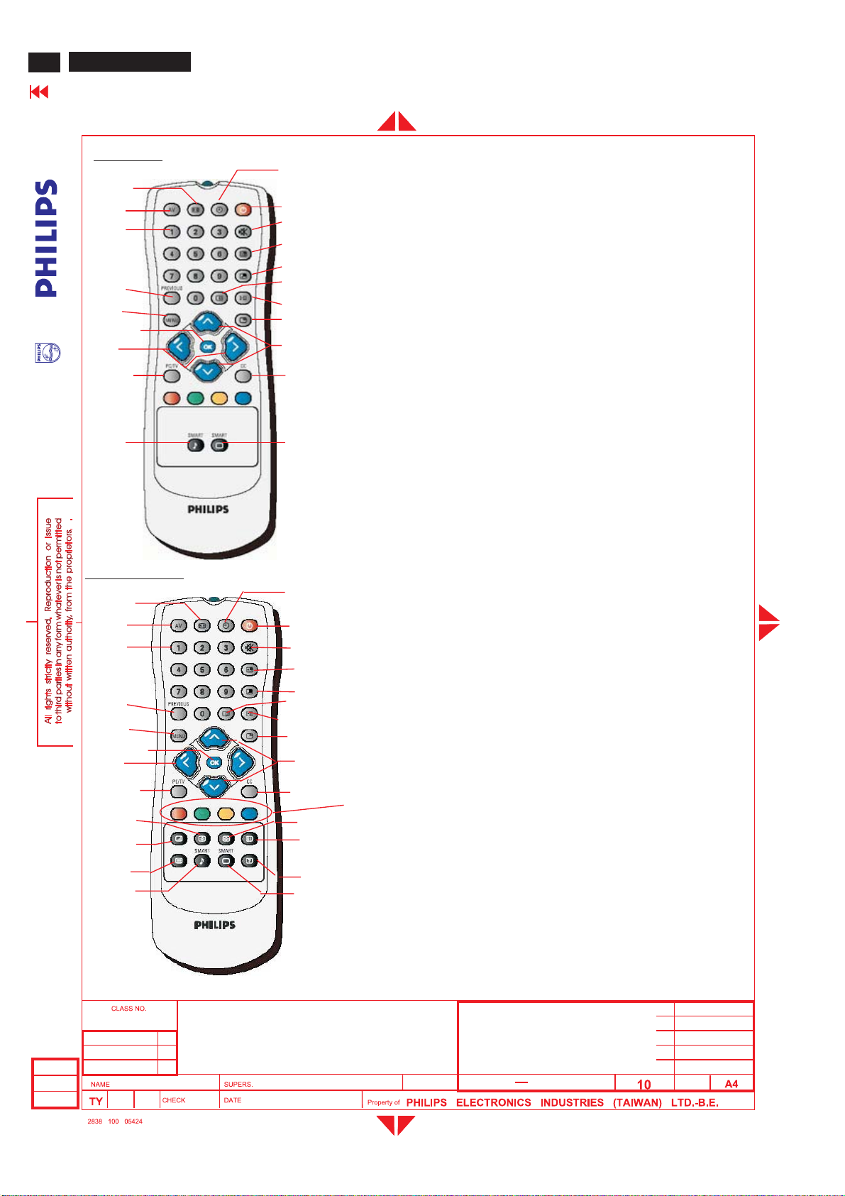
BDL3221 LCD/TV
78
Go to cover page
NAFTA mod el
5
7
9
GENERAL PRODUCT SPECIFICATION(Continued)
3.2.3.2 Remote control key definition
3
4
6
8
10
2
16
15
1
20
17
14
13
19
18
1211
1.Power: Power On/Standby key
2.Sleep timer: 15,30,60, 120,180,240 OFF
3.Display Format: Picture format with Wide screen/4:3/Zoom
4. AV: Source selection
5.Numerica keys : (0~9) ,Channel setting
6.Previous : Return previous program
7.Menu: Main menu s elect
8.OK: Ok key
9.</> : Direction Left/ right for OSD and
10.PC/TV : Source change between PC and TV
11.Smart sound: Smart sound hot key
12.Smart picture: Smart picture hot key
13.CC: Closed caption on/off
14.^ / v : Direction up/down for OSD
15.Freeze picture: Freez e picture function
16.I-II: (2
17.Status OSD : Display OSD status
18.PIP size: PIP size selection
19.PIP position : PIP position hot key
20.Sound mute function
16:9/Supper Wide
adjust ment/VO L+/VOL-
and adjustment/CH+/CH-
nd
audio) Sound select
WE/AP/Chi na Mod el
3
4
5
6
7
8
9
10
11
12
13
14
23
2
22
20
24
1
27
21
26
25
18
15
17
16
1.Power: Power On/Standby key
2.Sleep timer: 15,30,60, 120,180,240 OFF
3.Display Format: Picture format with Wide screen/4:3/Zoom
4. AV: Source selection
5.Numerica keys : (0~9) ,Channel setting
6.Previous : Return previous program
7.Menu: Main menu s elect
8.OK: Ok key
9.</> : Direction Left/ right for OSD and
10.PC/TV : Source change between PC and TV
11.Teletext Enlarge: Teletext Enlarge
12.Teletext Mix : Teletext Mix hot key
13.Teletext On/Off : Teletext On/Off hot key
14. Smart sound: Smart sound hot key
15.Smart picture: Smart picture hot key
16.Reveal/Conceal
17.Teletext OSD main Index
19
18.Teletext Hold
19.Teletext access
20. CC: C losed c aption on/of f (disable)
21. .^ / v : Direction up/down for OSD
22. Status OSD : Display OSD status
23..I-II: (2
24. Freeze picture: Freeze picture function
25. PIP size: PIP size selection
26 .PIP Position: PIP position hot key
27.Sound mute function
16:9/Supper Wide
adjust ment/VO L+/VOL-
and adjustment/CH+/CH-
nd
audio) Sound select
All PC or TV OSD menu function could be accomplished by remote control.
32 inch BDS WXGA TFT LCD Monitor/TV
TYPE : BDL3221V/00
BRAND : PHILIPS
2005-06-17
Freud Yu
32
2005-06-17
590
8639 000 16304
7
Page 79
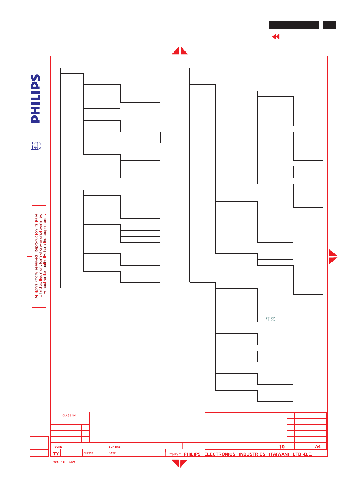
GENERAL PRODUCT SPECIFICATION(Continued)
BDL3221 LCD/TV
Go to cover page
3.2.4 OSDMenu
3.2.4.1 PC Si gnal con trol:
PICTURE
SMART
PICTURE
NORMAL PIP
WARM SIZE
PCMAIN MENU
AUDIO ICON1
BRIGHTNESS SMALL
CONTRAST MEDIUM
AUTOADJUST LARGE
MANUAL
ADJUST S-VIDEO
SMART SOUND ICON2
SETTINGS AV
VIRTUA L
SURROUNDZOOM
AVL OFF
COOL OFF
YES PBP
STORE VIDEO
YES TV
NO AV
PHASE EXT
CLOCK AUDIO
HORIZONTAL PC
VERTICAL PIP
MUSIC SOURCE ICON3
THEATRE PC ICON4
NEWS DVI
PERSONALTV
TREBLES-VIDEO
BASS HD
BA LANCEEXT
ON ZOOM ID
OFF ZOOMTYPE
YES 4X4
NO INSTALL 3X3
FEATUR ES
DISPLA Y
LANGUAGE 2X2
ENGLISH 1X5
DEUTSCH
FRANÇ AIS
ITALIANO
ESPAÑ OL
79
2005-06-17
Freud Yu
32 inch BDS WXGA TFT LCD Monitor/TV
TYPE : BDL3221V/00
BRAND:PHILIPS
32
2005-06-17
MONITOR ID
DCR
LIGHT SENSOR
REMOTE
CONTROL
FACTORY RESET
8639 000 16304
590
ON
OFF
ON
OFF
ON
OFF
NO
YES
8
Page 80
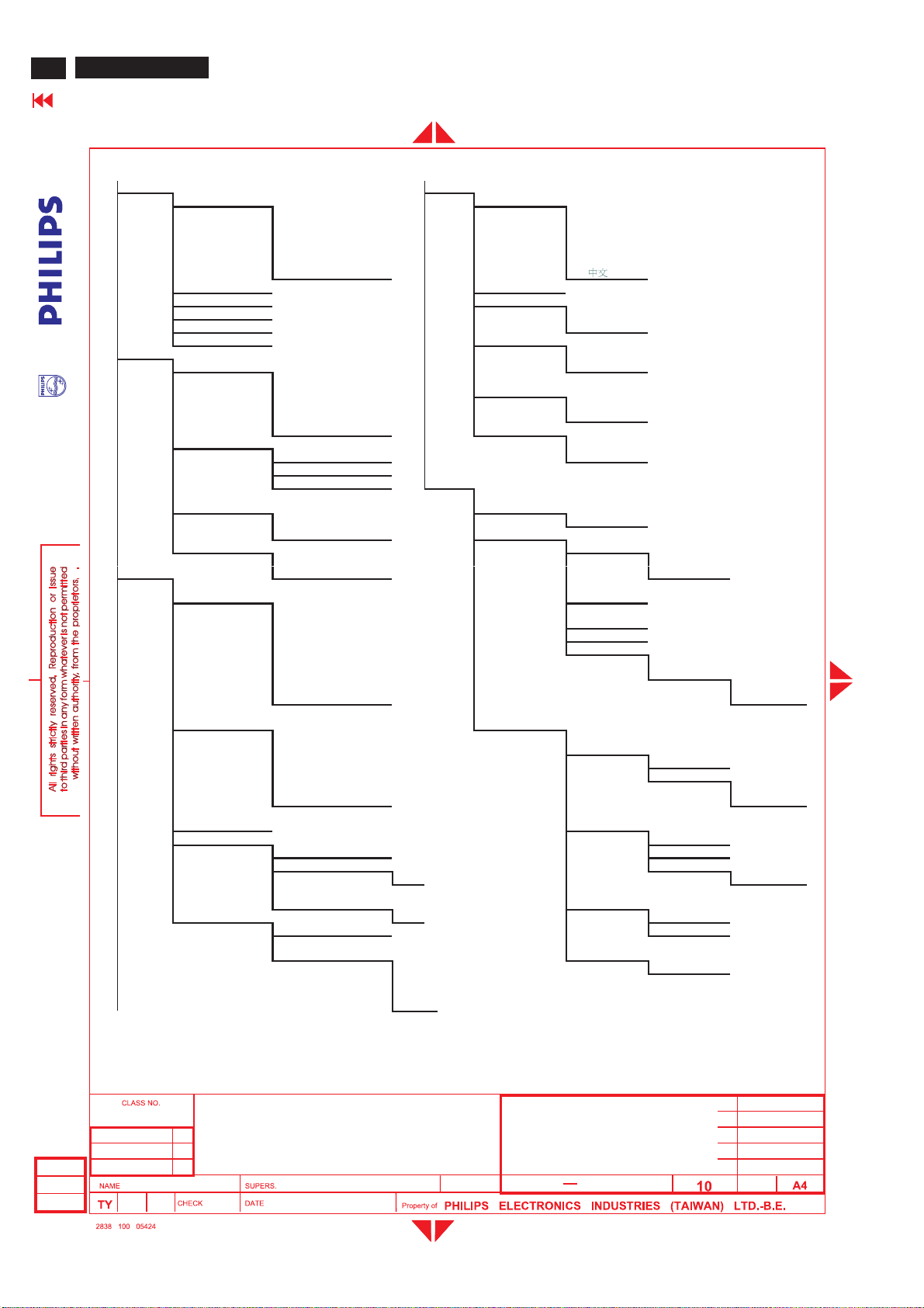
BDL3221 LCD/TV
80
Go to cover page
3.2.4.2 TV Si g n al cont r o l:
WE /AP/Chi na
PICTURE INSTALL
TV MA IN MENU
AUDIO ON
FEATURES NO WEST EUROPE
GENERAL PRODUCT SPECIFICATION(Continued)
SMART PICTURE LANGUAGE
BRIGHTNESS MONITOR ID
CONTRAST DCR
COLOR ON
SHARPNESS OFF
TINT LIGHT SENSOR
SMART SOUND OFF
SETTINGS NO
VIRTUAL
SURROUND
AVL SYSTEM
SOURCE PC
PICTURE FORMAT
PICTURE
ALIGNMENT
AUTO LOCK FROM
ZOOM OFF CHANNEL
SPORTS ENGLISH
MOVIES DEUTSCH
WEAK SIGNAL FRANÇAIS
NIGHT ITALIANO
MULTIMEDIA ESPA Ñ OL
PERSONAL
MUSIC
THEA TRE ON
NEWS OFF
PERSONAL FA CTORY RESET
TREBLE YES
BASS
BALANCE SETUP
ON START
OFF MAN UA L STORE
YES FRANCE
DVI
HDCP
TV FINE TUNE
AV STORE
S-VIDEO YES
HD STORE
EXT YES
AU TOMA TIC
4:3 CHANNEL
ZOOM 16:9 SK IP
WIDESCREEN ACTIVATE
SUPER WIDE SKIP
LOCK PROGRA M TO
CHANGE CODE EXCHANGE
CLEAR ALL ON
ZOOM ID NAME
ZOOM TYPE OFF
YES EXCHANGED
4X4 SORT
3X3
2X2
1X5
REMOTE
CONTROL
AUTO PROGRAM
CHANNEL
SETTING
MAN UA L
STORE
PROGRAM
NUMBER
CHANNEL
EDIT
CHANNEL
SWAP
NAME
EDIT
CHANNEL
SORT
NO
2005-06-17
Freud Yu
32 inch BDS WXGA TFT LCD Monitor/TV
TYPE : BDL3221V/00
BRAND : PHILIPS
32
2005-06-17
8639 000 16304
590
9
Page 81
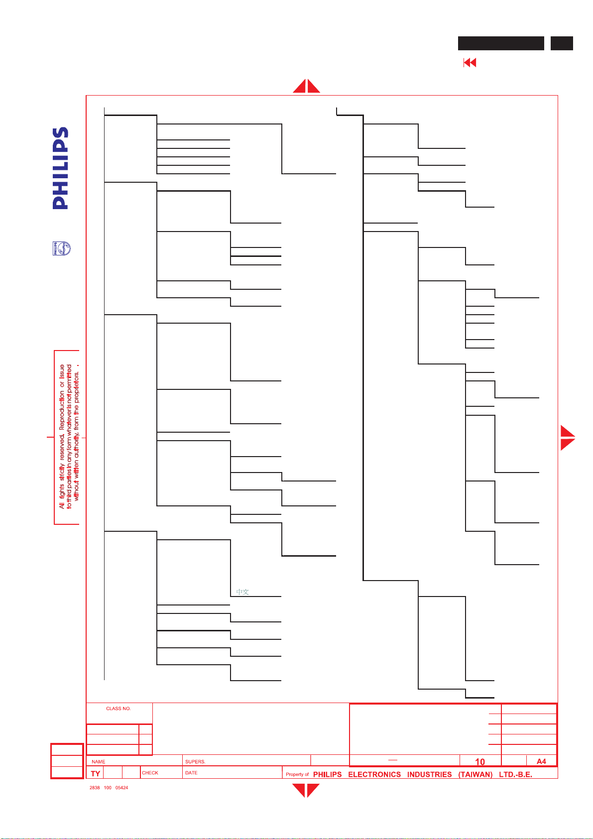
GENERAL PRODUCT SPECIFICATION(Continued)
NAFTA model
PICTURE SETUP
TV MAIN MENU
AUDIO CHANNEL
FEATURES PG13
INSTALL 4X4 TV MA
SMART PICTURE TUNER MODE
BRIGHTNESS MOVIES CABLE
CONTRAST WEAK SIGNA L AUTO
COLOR NIGHT AUTOPROGRAM
SHARPNESS MULTIMEDIA START
TINT PERSONAL CHANNEL EDIT
SMART SOUND MUSIC SKIP
SETTINGSRATING
VIRTUAL SURROUND ON
AVL YES OFF
SOURCE PC R
PICTURE FORMAT AUTOMATIC BLOCK
PICTURE AL IGNMENT V
AUTO LOCK S
ZOOM OFF S
LANGUAGE ENGL ISH 3X3 BLOCK
MONITOR ID CC1
DCR ON CC2
LIGHT SENSOR ON CC4
REMOTE CONTROL ON TXT2
FACTORY RESET NO TXT4
THEATRE ACTIVATE
NEWS SKIP
PERSONAL
TREBLE
BASS ON
BALANCE OFF
OFF G ON
NO PG
DVI
HDCP NC17
TV X
AV
S-VIDEO TV RATING
HD TV Y
EXT TV Y7
4:3 FV
ZOOM 16:9 TV G
WIDESCREEN TV PG
SUPER WIDE BLOCK
LOCK
PROGRAM L
CHANGE
CODE D
CLEA R ALL BLOCK
ZOOM ID L
ZOOMTYPE OFF D
DEUTSCH 2X2 V
FRANÇ AIS 1X5 S
ITALIANO L
ESPANOL
OFF CC3
OFF TXT1
OFF TXT3
YES
SPORTSANTENNA
MANUA L FINE
TUNE
BLOCK
OPTION
MOVIE
RATING
YES TV 14
ON V
CLOSED
CAPTION
CAPTION
MODE
CC DISPLA Y ON
BDL3221 LCD/TV
Go to cover page
CC
MUTE
OFF
81
2005-06-17
Freud Yu
32 inch BDS WXGA TFT LCD Monitor/TV
TYPE : BDL3221V/00
BRAND:PHILIPS
32
2005-06-17
8639 000 16304
590
10
Page 82
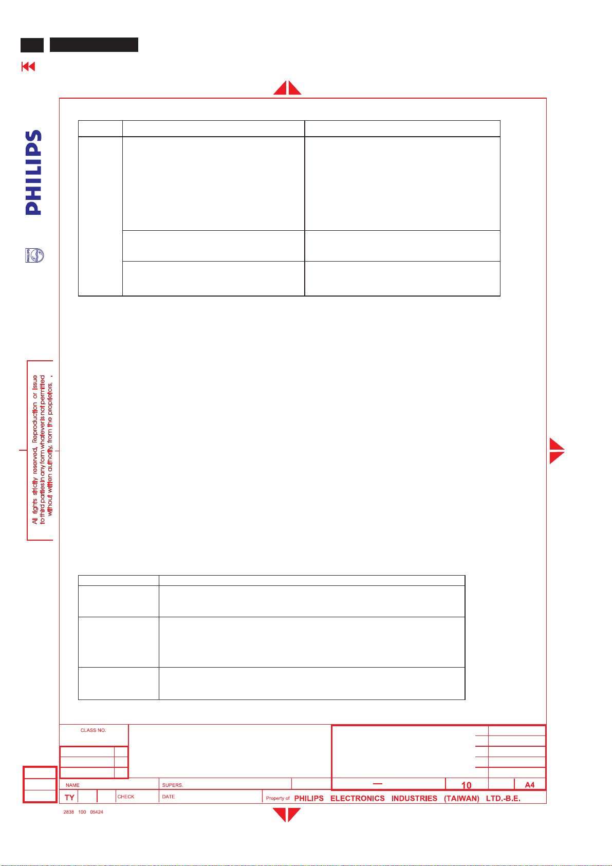
BDL3221 LCD/TV
82
Go to cover page
3.2.4.3 OSD messages
GENERAL PRODUCT SPECIFICATION(Continued)
Message When
·
Dot Rate higher than 103MHz
Horizontal frequency does not fall into
Cannot Display This Video Mode,
Change computer input to 1366x768 @ 60Hz
OSD
attention
signal
No Video Input No video signal input as monitor power on.
Use 1366 x 768 for best Result. When input signal's resolution is below 1366 x 768
· Attention Signal off
Above attention signals can be switched off by pressing "UP" and "DOWN" key together for more than 10
seconds if there is no video signal in. The Attention signal "Attention signals on"or"Attention signal off"
appears for 3 seconds.
between 30 and 61kHz
·
Vertical frequency does not fall
between 56Hz and 75Hz (NonInterlaced)
·
Resolution higher than 1366x768
3.2.4.4 OSD Loc k
OSD function can be locked by
· Pressing "Menu" button for more than 10 seconds while there is video signal in.
The screen automatically shows OSD MAIN MENU LOCKED for 3 seconds.
When users press "Menu" button, OSD Lock MENU will appear, and the default cursor location will be on unlock.
· Using RS232 command.
OSD can be unlocked by
· Pressing front panel "Menu" button for more than 10 seconds while there is video signal in. As the menu button is
pressed, the screen will keep showing OSD MAIN MENU LOCKED until OSD function unlocked. Then, OSD MAIN
MENU UNLOCK will automatically show for 3 seconds.
· Using RS232 command.
3.2.4.5 Hid den fun ction s
The following hidden functions are available for development and service personnel only, not for end customers.
Function Description
OSD lock / unlock
Factory Mode
Press "Menu" button for more than 10 seconds while there is video signal in.
·
To hold "Menu + DOWN" buttons, then Power on while there is
video signal in. Monitor will exit factory mode automatically once
power is off.
·
Press remote control code "062596", then press menu key.
Switch on / off
attention signals
2005-06-17
Freud Yu
To press "UP" and "DOWN" key together for more than 10 seconds while is no
video signal in.
32 inch BDS WXGA TFT LCD Monitor/TV
TYPE : BDL3221V/00
BRAND : PHILIPS
32
2005-06-17
8639 000 16304
590
11
Page 83
GENERAL PRODUCT SPECIFICATION(Continued)
3.2.5 RS232 Con trol
9pin D-Subconnector, for RS232 interface wi th pin assignmentasfollows:
PIN No. SIGNAL
1 Not used
2MRXD
3MTXD
4 Not used
5GND
6 Not used
7 Not used
8 Not used
9 Not used
The communication protocol dividedinto 5 groups. The simulation test program
Can select necessary items to assure RS232 port function well.
Group1(Geometry Gr oup):
HORIZONTAL POSITION
VERTICAL POSITION
SCREEN MOD
VIDEO MODE
PIP SIZE
PIP POSITION
E
BDL3221 LCD/TV
Go to cover page
83
Group2(MiscellaneousGroup):
STATUS
OPERATION HOURS
LIGHT SENSOR
FACTORY RESET
SLEEP TIMER
CLOSEDCAPTION
TV SYSTEM
CHANNEL SEARCH
Group3(Picture Group)
LANGUAGE
BRIGHTNESS
CONTRAST
AU
TOADJUST
PHASE
PIXELCLOCK
COLOR SETTING
REDCOLOR
GREEN COLOR
BLUE COLOR
VIDEO COLOR
SHARPNESS
TINT
COLOR TEMPERATURE
INPUT SELECT
PIP VIDEO SOURCE
Group4(AudioGroup):
SMART SOUND
TREBLE
BASS
BALANC
VOLUME
SURROUND
MUTE
E
Group5(DebugGroup)
2005-06-17
Freud Yu
32 inch BDS WXGA TFT LCD Monitor/TV
TYPE : BDL3221V/00
BRAND:PHILIPS
32
2005-06-17
8639 000 16304
590
12
Page 84
BDL3221 LCD/TV
84
Go to cover page
3.3 PC and TV r equ irem en t
GENERAL PRODUCT SPECIFICATION(Continued)
3.3.1 PC int er f ac e
3.3.1.1 Mode s tor ing capacit y
3.3.1.2 Horizontal scanning
3.3.1.3 Ver tical s c an n ing
3.3.1.4 Inpu t co n necto r s
A. Input analog D-sub connector pin assignment B. Output analog D-sub connector pin assignment
PIN No. SIGNAL (PC)
1Red
2Green
3Blue
4GND
5GND
6RedGND
7GreenGND
8BlueGND
9 +5V (S upply from PC)
10 Sync GND
11 GND
12 Bi-directional data
13 H-sync
14 V-sync
15 Data clock
Pre-set : 12
User modes : 12
New modes : 8
Sync polarity : Positive or Negative
Scanning frequency : 30 - 63 KHz
Sync polarity : Positive or Negative
Scanning frequency : 56 - 75 Hz
PIN No. SIGNAL
1 Red_OUT
2 Green_OUT
3 Blue_OUT
4GND
5GND
6RedGND
7GreenGND
8BlueGND
9GND
10 Sync GND
11 GND
12 GND
13 H-sync_OUT
14 V-sync_OUT
15 GND
- 1.8m 15Pins D-sub male with DDC2B Pin assignments.
32 inch BDS WXGA TFT LCD Monitor/TV
TYPE : BDL3221V/00
BRAND : PHILIPS
2005-06-17
Freud Yu
2005-06-17
32
8639 000 16304
590
13
Page 85
GENERAL PRODUCT SPECIFICATION(Continued)
C. DVI-D : Pin assignment (for PCDVI and Video HDCP)
Pin No. Description
1 RX2-
2 RX2+
3GND
4GND
5GND
6DDCclock
7DDCdata
8GND
9 RX1-
10 RX1+
11 GND
12 GND
13 GND
14 +5V
15 GND
16 +5V
17 RX0-
18 RX0+
19 GND
20 GND
21 GND
22 GND
23 RXC+
24 RXC-
BDL3221 LCD/TV
Go to cover page
85
3.3.1.5 A vailable timings
Remark : Mode 1,3,4,5,7,9,11 will run auto adju stmentonly, and W/O QA checking
MODENO.1 2 3 4
RESOLUTION 640 x 350 640 x 480 640 x 480 720 x 400
Dot clock(MHz) 25.175 25.175 31.500 28.321
f h 31.469kHz 31.469kHz 37.500kHz 31.469kHz
A(us ) 31.778 (800 dots) 31.778 (800 dots) 26.667 (840 dots) 31.78(900dots)
B (us ) 3.813 ( 96 dots) 3.813 ( 96 dots) 2.032 ( 64 dots) 3.813(108dots)
C (us ) 1.907 ( 48 dots) 1.907 ( 48 dots) 3.810 ( 120 dots) 1.907(54dots)
D (us ) 25.422 (640 dots) 25.422 (640 dots) 20.317 ( 640 dots) 25.42(720dots)
E(us ) 0.636 ( 16 dots) 0.636 ( 16 dots) 0.508 ( 16 dots) 0.636(18dots)
f v 70Hz ( 70.086 ) 60Hz ( 59.940 ) 75Hz (75 ) 70Hz(70.087)
O(ms ) 14.268 ( 449 lines) 16.683 (525 lines ) 13.333 (500 lines) 14.27(449 lines)
P(ms ) 0.064 (350 lines ) 0.064 ( 2lines ) 0.080 ( 3lines) 0.064(2lines)
Q (ms ) 1.715 ( 54 lines ) 1.049 ( 33 lines ) 0.427 ( 16 lines) 1.112(34 lines)
R(ms ) 11.122 ( 350lines ) 15.253 (480 lines ) 12.80 (480 lines) 12.71(400 lines)
S(ms ) 0.192 ( 6lines ) 0.317 ( 10 lines) 0.027 ( 1line ) 0.384(13 lines)
SYNC. H/V +/- - / - - / - -/+
POLARITY
SEP . SYNCY Y Y Y
Factory pre-set t iming, size and centering are accordingtothereference
timingcharts,Thelist is as below:
32 inch BDS WXGA TFT LCD Monitor/TV
2005-06-17
Freud Yu
TYPE : BDL3221V/00
BRAND:PHILIPS
32
2005-06-17
8639 000 16304
590
14
Page 86
BDL3221 LCD/TV
86
Go to cover page
GENERAL PRODUCT SPECIFICATION(Continued)
MODE NO. 5 6 7 8
RESOLUTION 800 x 600 800 x 600 800 x 600 1024 x 768
Dot clock(MHz) 36.000 40.000 49.500 65.000
f h 35.156kHz 37.879kHz 46.875kHz 48.363kHz
A ( us ) 28.44 (1024 dots) 26.40 (1056 dots) 21.333 (1056dots) 20.677(1344 dots)
B ( us ) 2.000 ( 72 dots) 3.200 ( 128 dots) 1.616 ( 80 dots) 2.092(136 dots)
C ( us ) 3.556 ( 128 dots) 2.200 ( 88 dots) 3.232 ( 160 dots) 2.462(160 dots)
D ( us ) 22.22 ( 800 dots) 20. 00 ( 800 dots) 16.162 ( 800 dots) 15.754(1024 dots)
E ( us ) 0.667 ( 24 dots) 1.000 ( 40 dots) 0.323 ( 16 dots) 0.369(24 dots)
f v 56Hz ( 56.250) 60Hz ( 60.316) 75Hz ( 75.000) 60.004Hz
O (ms ) 17.78 (625 lines) 16.58 (628 lines) 13.333 (625lines) 16.666(806 lines)
P ( ms ) 0.057 ( 2 lines) 0.106 ( 4 lines) 0.064 ( 3 lines) 0.124(6 lines)
Q (ms ) 0.626 ( 22 lines) 0.607 ( 23 lines) 0.448 ( 21 lines) 0.600(29 lines)
R ( ms ) 17.07 ( 600 lines) 15.84 (600 lines) 12.80 (600lines) 15.880(768 lines)
S ( ms ) 0.028 ( 1 lines) 0.026 ( 1 line ) 0.021 ( 1 line ) 0.062(3 lines)
SYNC. H/V + / + + / + + / + -/-
POLARITY
SEP . SYNC Y Y Y Y
MODE NO. 9 10 11 12
RESOLUTION 1024 x 768 1280 x 720 1280 x 768 1360 x 768
Dot clock(MHz) 78.750 74.5 79.50 84.75
f h 60.023kHz 44.772kHz 47.776kHz 47.720kHz
A ( us ) 16.66 (1312dots) 22.336 (1664 dots) 20.931 (1664 dots) 20.956 (1776dots)
B ( us ) 1.219 ( 96 dots) 1.718 ( 128 dots) 1.610 ( 128 dots) 1.605 ( 136 dots)
C ( us ) 2.235 ( 176 dots) 2.577 ( 192 dots) 2.415 ( 192 dots) 2.454 ( 208 dots)
D ( us ) 13.00 (1024dots) 17. 18 (1280 dots) 16.10 (1280 dots) 16.047(1360dots)
E ( us ) 0.203 ( 16 dots) 0.859 ( 64 dots) 0.805 ( 64 dots) 0.850( 72 dots)
f v 75Hz ( 75.029) 60Hz (59.855) 60Hz (59.87) 60Hz (59.799)
O (ms ) 13.328 (800 lines) 16.707 (748 lines) 16.703 (798 lines) 16.723 (798 lines)
P ( ms ) 0.050 ( 3 lines) 0.117 ( 5 lines) 0.1455 ( 7 lines) 0.105 ( 5 lines)
Q (ms ) 0.466 ( 28 lines) 0.4477 ( 20 lines) 0.4186 ( 20 lines) 0.461( 22 lines)
R ( ms ) 12.795 (768 lines) 16.082 (720 lines) 16.075 (768lines) 16.094 (768 lines)
S ( ms ) 0.017 ( 1 line) 0.067 ( 3 lines) 0.0628 ( 3 lines) 0.063 ( 3 lines)
SYNC. H/V +/+ -/+ -/+ -/+
POLARITY
SEP . SYNC Y Y Y Y
A : H-Total O : V-Total
B:H-Syncwidth P:V-Syncwidth
C : H- Back porch Q :.V- Back porch
D:H-Videowidth R:V-Videolength
E : H- Front porch S :.V- Front porch
CVT CVT CVT
2005-06-17
Freud Yu
32 inch BDS WXGA TFT LCD Monitor/TV
TYPE : BDL3221V/00
BRAND : PHILIPS
32
2005-06-17
8639 000 16304
590
15
Page 87
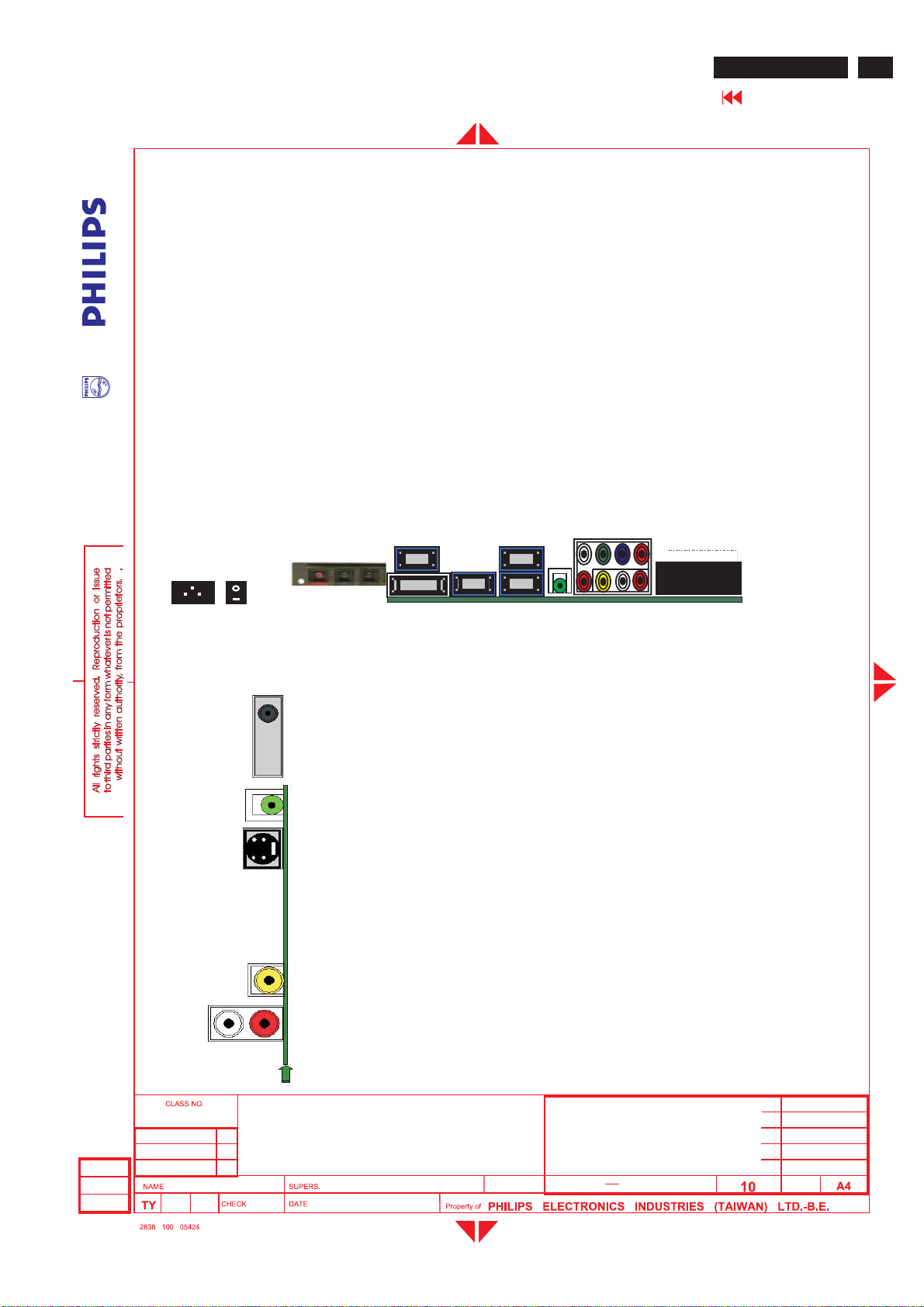
GENERAL PRODUCT SPECIFICATION(Continued)
3.3.2 I/Ointerface
Connectors:
1. Tuner: RTMA M/N system reception for NAFTA model
Multi-standard for WE model
Multi-standardPAL/NTSCforAP model
PAL D/K for Chinamodel
2. DVIIN:DVIinput (PCand TV digital signal s upport HDCP) with share with VGA audio IN .
3. PC IN:VG
4. HD IN:HDTVin putwi th YPbPrformatwith R/L audio in.
5. AV OUT: Composite video output (CVBS) and audio R/L(RCA jack).
6. AV IN :Video (CVBS) and S-Video share with same audio R/L.
7. EXT IN:Vid
8. Headphoneout
9. VGA out: VGA loop through.
10. RS232 in/out:For control .
Location:
Rear down side
Ainput (D-SUBconnectors) with audio R/L(mini-jack).
eo (CVBS), S-Video and RGB input, TV AVoutput.
BDL3221 LCD/TV
Go to cover page
87
AC
Inlet
AC Switch
Rear left Side
Speaker
connector
TUNER Box
Headphoneout
S-video in
VGA
out
DVI
in/
HDCP
VGA
in
RS23
2 out
RS23
2
IN
IN
HD/AudioL/R
in
VGA
audio
in
EX
T
AV
/Audio
L/R
output
2005-06-17
Freud Yu
AV in
S-Video/AV
audioL/Rin
32 inch BDS WXGA TFT LCD Monitor/TV
TYPE : BDL3221V/00
BRAND:PHILIPS
32
2005-06-17
8639 000 16304
590
16
Page 88
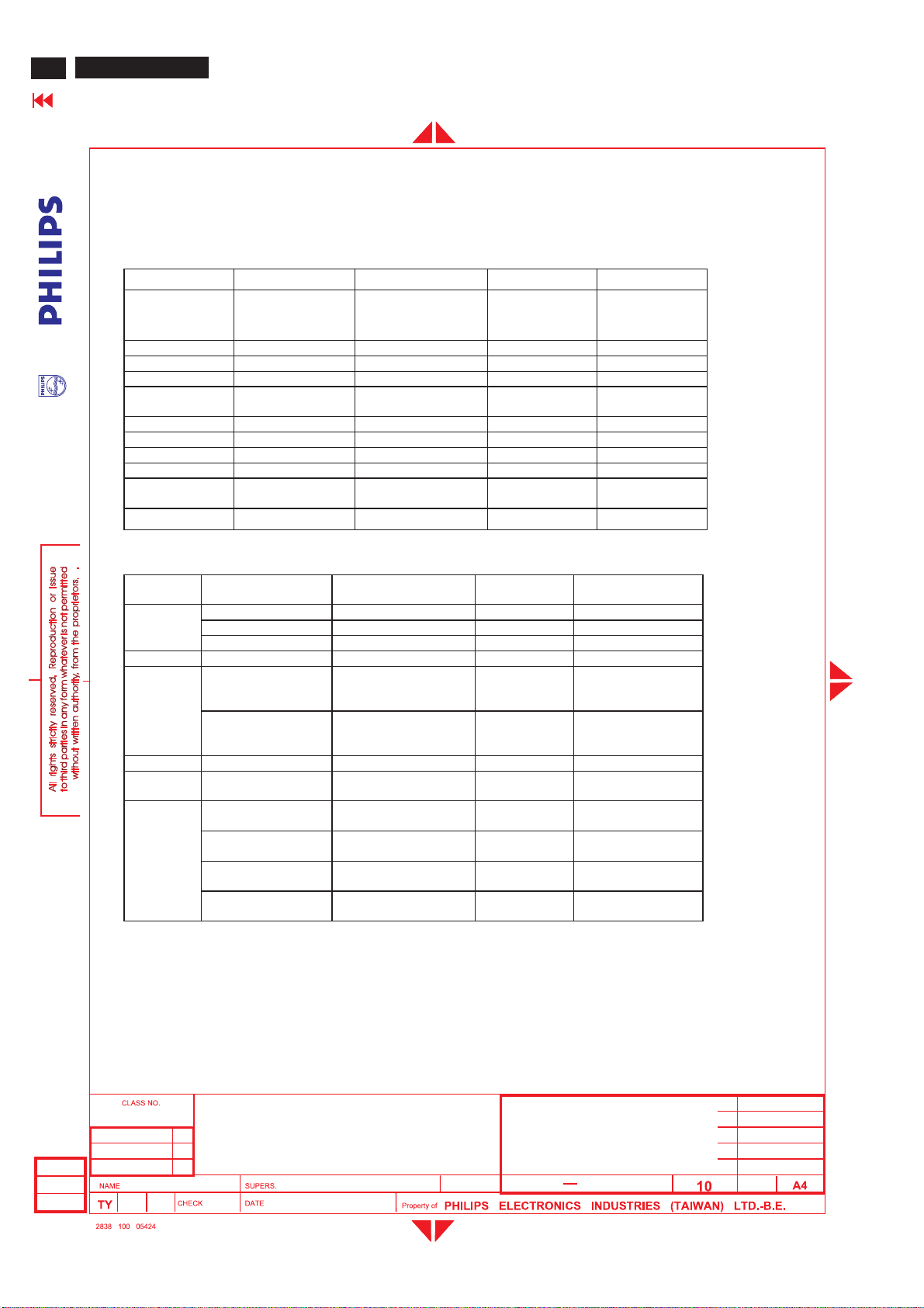
BDL3221 LCD/TV
88
Go to cover page
3.3.3 TV In t erf ac e
3.3.3.1 TV Tu n er RF input : Aerial or Cable Input impedance 75 ?
3.3.3.2 Deviatio n of TV s ystem
GENERAL PRODUCT SPECIFICATION(Continued)
Following table is the deviation of main TV system.
Model W EUROPE America AP China
Tuner FQ1216ME5/I H-5
TV Color system PAL, SECAM NTSC PAL/NTSC PAL
V system B/G, D/K, I, L M B/G, NTSC-M D/K
Sound decoder MSP3450G MSP3450G MSP3450G MSP3450G
CVBS, YC
Color system
Scaler MCU WE version NAFTA version AP version China v ersion
Closed caption N Y N N
V-chip N Y N N
Teletext Y N Y N
Remote controller
(RC5)
Channel number 100 US Air 68, cable 125 100 100
Picture carrier
38.9MHz
Multi Multi Multi Multi
WE version NAFTA version WE version WE version
FQ1236/F H-5
Picture carrier
45.75MHz
FQ1216PN/I H-5
Picture carrier
38.9MHz
FQ1256/I H-3
Picture carrier
38MHz
Following table is the detail TV System list.
TV system Position of sound
M
N 4.5 BTSC-stereo SAP PAL Argentina
B/G
L 6.5/5.85 AM-Mono/NICAM SECAM-L France
I 6.0/6.552 FM-Mono/NICAM PAL Great Britain, Hong
D/K
3.3.3.3 TV c olo r sett i ng
carrier(MHz)
4.5/4.724212 FM-Stereo (A2) NTSC Korea
4.5 FM-FM (EIA-J) NTSC Japan
4.5 BTSC-stereo SAP NTSC USA
5.5/5.7421875 FM-stereo (A2) PAL Germany, Austria,
5.5/5.85 FM-Mono/NICAM PAL Belgium, Spain,
6.5/6.2578125 FM-Stereo
6.5/6.7421875 FM-Stereo
6.5/5.7421875 FM-Stereo
6.5/5.85 FM-Mono/
There are three color for factory to select and the pr eset color is cool.
Sound system Color system Country
Switzerland, Italy,
Netherlands.
Denmark, Finland,
Norway, Sweden.
Kong, Ireland.
SECAM-East Slovak. Rep.
(A2, D/K1)
PAL None
(A2, D/K2)
SECAM-East Poland
(A2, D/K3)
PAL China, Hungary
NICAM (D/K, NICAM)
3.3.3.4 TV audio s et ting
2005-06-17
Freud Yu
Sound power outputs:
- Stereo: 2 x 10 Watts, THD 10%
Sound controls:
32 inch BDS WXGA TFT LCD Monitor/TV
TYPE : BDL3221V/00
BRAND : PHILIPS
32
2005-06-17
8639 000 16304
590
17
Page 89
GENERAL PRODUCT SPECIFICATION(Continued)
- Treble
-Bass
-Balance
-Volume adjust
- Surround sound on/off
-Mute on/off (Speaker on/off )
- Smart sound ( Personal , News , Music,Theater)
Sound mute :
-Whennovideo recognition on terrestrial tuner signal,
the sound must be muted
3.3.3.5 TV special setting
BDL3221 LCD/TV
Go to cover page
89
Teletext : (For WE,Tuner ,CVBSinputsource only)
Close Captio n,V-chip (For NAFTA---Tuner ,CVBSinputsource only)
3.3.4 Electriccharacteristics of I/O
3.3.4.1 PC Si gnal type
Analog Video : 0.7 Vp-p linear, positive polari
Separate Sync. : TTL level, separate, positive or negative polarity
Signal source : pattern generator format as attachment. (Table 1 to 6)
Reference generator: CHROMA 2200 or 2250
PC Audio input
Location: Rear down side
Specification
-TXTon/off
- Enlarge
-Hold
- Reveal
-Mix
-Quick search from color keys
- CC-1 .... CC-4 , CC_MUTEdecodingand display
- TXT1.....TXT4 Text mode
-support violence ratingand checking(V-chip)
ty
AudioL/Rinput
- Nominal :0.5Vrms.
-Maximum:1.5Vrms.
- Impedance > 10 k W.
3.3.4.2 TV Signal ty pe
2005-06-17
Freud Yu
Note : the inp
Connectortype:3.5mmmini Jack
ESD-protected :15kV
utwill be overloaded when the signal > 1.5 V rms.
32 inch BDS WXGA TFT LCD Monitor/TV
TYPE : BDL3221V/00
BRAND:PHILIPS
32
2005-06-17
8639 000 16304
590
18
Page 90
BDL3221 LCD/TV
90
Go to cover page
GENERAL PRODUCT SPECIFICATION(Continued)
RF signal
Aerial input / 10mV(80dBuV)
HD / Component Y Pb Pr Video input , Audio input
S-Vi deo Video input, Audio input
Specification
AV input
Location : Rear down side
Specification
Video - Y : 700mV, Pb, Pr, : +/- 350mV,
- Impedance : 75 W
Audio: L/R input
- Nominal : 0.5 V r ms.
-Maximum:1.5Vrms.
- Impedance > 10 k W.
Note : the input will be overloaded when the signal > 1.5 V rms.
Connector type : RCA Jack
ESD-protected : 15 kV
Location : side
Video - Y : 1Vpp , C : 300 mV pp
- Impedance : 75? .
Audio L/R input (share with Composite Audio input )
- Nominal : 0.5 V r ms.
-Maximum:1.5Vrms.
-Impedance > 10 k W .
Note : the input will be overloaded when the signal > 1.5 V rms.
Connector type : RCA Jack
ESD-protected : 15 kV
Location : Side
Specific ation
Video - CVBS Source signal 1 Vpp
- Impedance : 75 W.
Audio L/R input (share with S-Video Audio input )
- Nominal : 0.5 V r ms.
-Maximum :1.5Vrms.
-Impedance > 10 k W.
Note : the input will be overloaded when the signal > 1.5 V rms.
2005-06-17
Freud Yu
Connector type : RCA Jack
ESD-protected : 15 kV
SCART input / output: ( f or WE model only )
Location : Rear down side
Specification : CV BS Video Audio signals input and output
FULL SCART according EN50049-1A3
The sound output s ignal on the connector must
bemutedincaseofnoterrestrialvideoinput
Connector ty pe : 21 pin black Euro connector
ESD protected : 15KV
SCART Pin assignment ( for WE model only )
32 inch BDS WXGA TFT LCD Monitor/TV
TYPE : BDL3221V/00
BRAND : PHILIPS
2005-06-17
32
8639 000 16304
590
19
Page 91
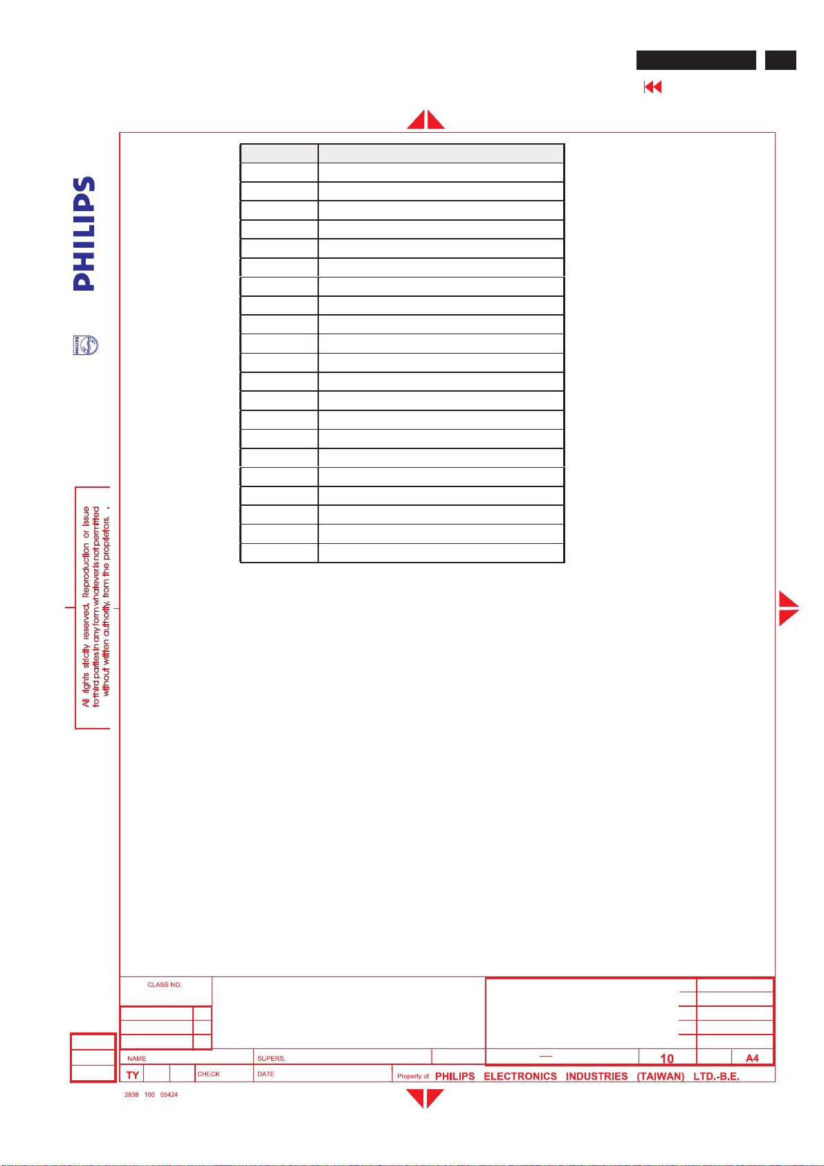
GENERAL PRODUCT SPECIFICATION(Continued)
PIN No. SIGNAL
1 AudiooutputB( right )
2 Audio inputB( right )
3 Audiooutput A(left )
4Ground (audio )
5Ground ( blue )
6 Audio input A(left )
7Blue input
8 Function select
9Ground ( green)
10 Comms data 2
11 Greeninput
12 Comms data 1
13 Ground ( red)
14 Ground ( blanking )
15 Redinput
16 RGB switchingcontrol
17 Ground ( video input&output )
18 Ground ( RGB switchingcontrol )
19 Video output ( composite )
20 Video input ( composite )
21 Common ground ( shield)
3.3.4.3 CVBS ou tput:
Location : Rear down side
Specification
Video - CVBS output. 1 Vpp ( from CVBS source )
- Impedance : 75 W .
AudioL/R output ( from CVBS source )
- Nominal : 0.5 V rms.
-Maximu m:1.5Vrms.
-Impedance > 10K W .
BDL3221 LCD/TV
Go to cover page
91
3.3.4.4 Head
3.3.5 Picture in Picture
3.3.5.1 Display function
·
PIP can only be functional for video and TV monitors.
·
PIP factory default isCVBS video input.
·
A black PIP display window will be s hownif there is n
32 inch BDS WXGA TFT LCD Monitor/TV
TYPE : BDL3221V/00
BRAND:PHILIPS
2005-06-17
Freud Yu
Connector type : RCA Jack
ESD-protected :15kV
phoneoutput:
Audio: R/L output 10mW at 32 W.
3.5mm stereo jack with switch
Impedance is between 8and 600
2005-06-17
ovideo signal inputwhile PIP on.
8639 000 16304
32
590
20
Page 92
BDL3221 LCD/TV
92
Go to cover page
GENERAL PRODUCT SPECIFICATION(Continued)
3.3.5.2 Display size
3.4 Power input connection
3.5 Power management
·
There are 4 different size of PIP, Small , medium , large and PBP
·
Press PIP key to start up the picture-in-picture display in small size. They will be operated in a carousel sequence:
·
PIP OFF > PIP small > PIP medium > PIP large > PBP > PIP OFF > ....
3.3.5.3 Display location
·
The location of PIP should be adjustable and be at the four corners of the monitor.
·
Press Menu key and select the PIP item in Feature menu, then access DISPLAY for PIP location adjustment.
3.3.5.4 Picture by Picture
·
The display is equally divided into two parts, one displays PC graphics, and another displays video input. This
selection item can be under PIP selection to reduce complexity of the menu.
3.3.5.5 Zoom
·
Four zoom modes will be provided: 4x4, 3x3, 2x2, and 1x5.
·
Zoom ID: Users can use either RS232C or OSD (via remote control) to select which portion of the entire image
to be shown. The ID will be designated as A1, A2, ..., B1, B2, in a row by row way.
Power cord length : 1.8 M
Power cord type : 3 leads power cord with protective earth plug.
PC mode
The power consumption and the status indication of the set with power management function are as follows:
STATUS Horizontal Vertical 120VAC230V
On Pulse Pulse (Typical 100W) BLUE
Stand-by No Pulse Pulse < 5 W < 5W Amber
Suspend Pulse No Pulse < 5 W < 5W Amber
Off No Pulse No Pulse < 5 W < 5 W Amber
DC Power switch off - - < 3 W < 3 W -
Power Spec
AC
LED
TV mode
The power consumption and the status indication of the set with power management function are as follows,
STATUS 120VAC230V
On (Typical 130W) BLUE
Stand-by < 5 W < 5 W Amber
DC Power switch off < 3W < 3W -
In Monitor power saving mode
Which no H&V sync or absent either H-sync or V-sync input via VGA connector. The monitor will enter "Monitor saving
mode". The way to wake up or change source:
1. H-sync and V-sync have signal again.
2. Press "Source" key on remote control, change to video source directly.
In TV power saving mode
Which switched off by RC "Power" key, SLEEP TIMER function or no TV signal input for 30 minutes, the monitor will
enter "TV standby mode" and LED shows amber color. The way to wake up:
1. Press "Power" key on remote control to return original video source.
2.Press "Source" key on remote control, change to video source directly.
,
,
Power Spec
LED
AC
32 inch BDS WXGA TFT LCD Monitor/TV
2005-06-17
Freud Yu
TYPE : BDL3221V/00
BRAND : PHILIPS
32
2005-06-17
8639 000 16304
590
21
Page 93
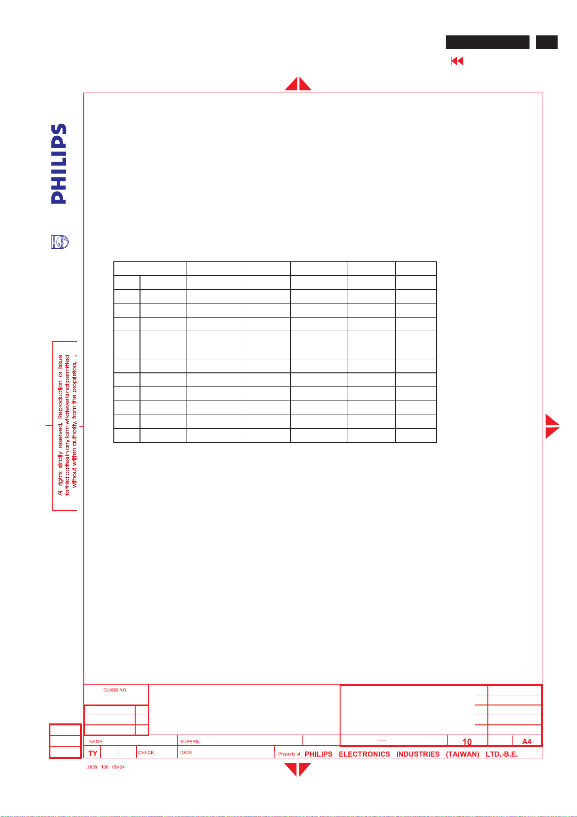
GENERAL PRODUCT SPECIFICATION(Continued)
4.0 Vis ual c haracter i sti cs
4.1 Test condit ion s
Unless otherwise specified,this specificationis definedunder the followingconditions.
(1)Inputsignal : As definedin3.3.1.5, 1360 x 768 x 60Hz non-interlaced mode (47.720kHz),signal
sources must have 75 ohm output impedance.
inance setting: controls to be set to 500 cd/m2(typical) with full screen 700mv white signal.
(2) Lum
(3) Warm up: more than 30 minutes after power on with signal supplied.
(4)Ambientlight: 400 ~ 600 lux.
(5)Ambienttemperature: 25 ± 2 °C
4.2 PC Resolution
Dot rate (MHz) H.f req (KHz) Mod e Resol uti on V.freq (Hz)Remark
1 25.175 31.469 VGA-1 640*350 70.086
2 25.175 31.469 IBM VGA 640 * 480 59.940
3 31.500 37.500 VGA 640 * 480 75.000
4 28.322 31.469 VGA 720*400 70.087
5 36.000 35.156 VESA 800 * 600 56.250
6 40.000 37.879 VESA 800 * 600 60.317
7 49.500 46.875 VESA 800 * 600 75.000
8 65.000 48.363 VESA 1024 * 768 60.004
9 78.750 60.023 VESA 1024 * 768 75.029
10 74.500 47.772 WXGA 1280 * 720 59.855 CVT
11 79.500 47.776 WXGA 1280 * 768 59.870 CVT
12 84.75 47.720 WXGA 1360 * 768 59.799 CVT
BDL3221 LCD/TV
Go to cover page
93
4.3 Bri ghtn es s
>400 cd/m
4.4 Im ag e si ze
4.4.1 Actual display size 697.685 x 392.256mm
4.5 Brightness unifor mity
Set contrastat100%and turn the brightness to Max. (Atoriginal color)
Apply the Fig1,itshould comply with the followingformula:
4.6 PC White color adjustment
Apply 1360x768@ 60Hz modesetsmartpicture to “Normal”,Apply full white pattern,with brightness in 50 %
position and the contrast control at 50% position.
The 1931 CIE Chromaticity (color triangle)diagram (X, Y) coordinate for the screen center should be:
2
at maximumcontrast and Brightness. (Atcenter of the screen, Fig. 1)
32 inch BDS WXGA TFT LCD Monitor/TV
TYPE : BDL3221V/00
BRAND:PHILIPS
2005-06-17
Freud Yu
Maximumluminance of five points (brightness)
¾¾¾¾¾¾¾¾¾¾¾¾¾¾¾¾¾¾¾¾ <1.3
Minimumlum
inance of five points (brightness)
32
590
2005-06-17
8639 000 16304
22
Page 94
BDL3221 LCD/TV
94
Go to cover page
For NORMAL COLOR
4.7 TV White color adjustm ent
4.8 TV p i cture centering
GENERAL PRODUCT SPECIFICATION(Continued)
Equivalent 6500°K X = 0.313 +/- 0.030
Y = 0.329 +/- 0.030
For COOL PRESET
Equivalent 9300 °K X = 0.283 +/- 0.030
Y = 0.297 +/- 0.030
For WARM PRESET
Equivalent 5700 °K X = 0.328 +/- 0.030
Y = 0.344 +/- 0.030
Smart picture set to personal for TV RF signal (80dBmv).
Use FLUKE 54200 pattern generator with full white pattern.
Use The 1931 CIE Chromaticity (color triangle) diagram (X, Y) coordinate for the screen center should be: 9300 °K
X=0.289+/-0.030,
Y=0.304+/-0.030.
Use CVBS (PAL and NTSC) input with cross hatch pattern to check the picture centering and should be
Left (size)-Right (size) < ± 3mm.
Up (size)-Down (size) < ± 3mm.
4.9 HD suppor t timin g
1920X1080I 60Hz
1920X1080I 50Hz
1280X720P 60Hz
1280X720P 50Hz
720X576P 50Hz
720X480P 60Hz
720X576i 50Hz
720X480i 60Hz
(For Quantum Data setting with Q801GD or Q802G with YPbPr mode.)
2005-06-17
Freud Yu
32 inch BDS WXGA TFT LCD Monitor/TV
TYPE : BDL3221V/00
BRAND : PHILIPS
32
2005-06-17
8639 000 16304
590
23
Page 95
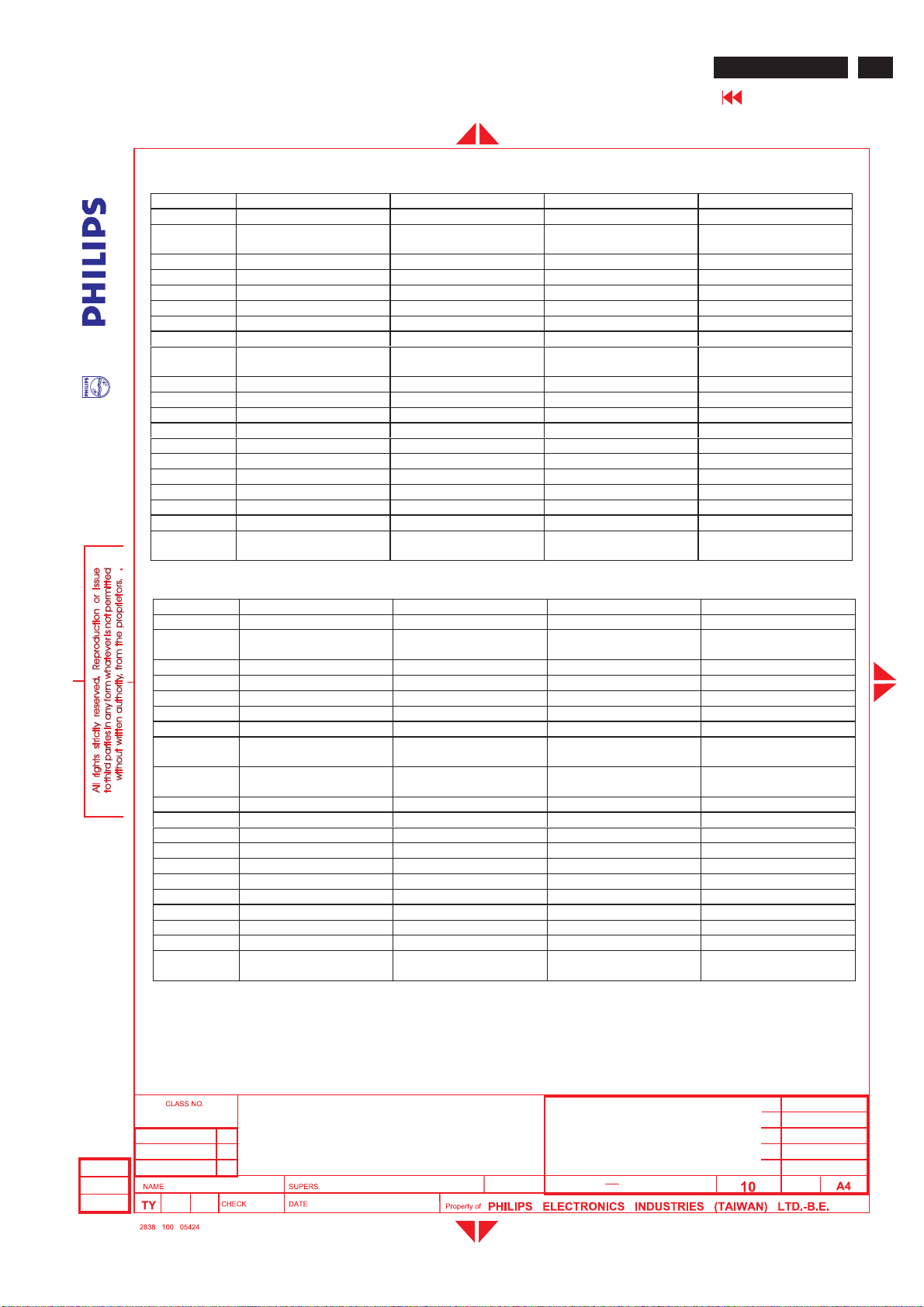
GENERAL PRODUCT SPECIFICATION(Continued)
BDL3221 LCD/TV
Go to cover page
4.9.1 HD detailtiming
Item 1920X1080i 60Hz 1280X720P 60Hz 1920X1080i 50Hz 1280X720P 50Hz
Pixel rate 74.25MHz (13.468 ns) 74.25MHz (13.468 ns) 74.25MHz ( 13.468ns ) 74.25MHz (13.468 ns)
Horizontal
Frequency
Active 1920 pixels (25.859 us) 1280 pixels (17.239 us) 1920 pixels (25.859 us) 1280 pixels (17.239 us)
Blank280pixels(3.771 us) 370 pixels(4.983 us) 720 pixels( 9.697 us ) 700 pixels(9.428 us)
Period 2200 pixels (29.630 us) 1650 pixels(22.222 us) 2640 pixels (35.556 us ) 1980 pixels(26.667 us)
Pulse delay 44 pixels(0.593 us) 70 pixels(0.943 us) 484 pixels( 6.519 us ) 400 pixels(5.387 us)
Pulse width 44 pixels(0.593 us) 40 pixels(0.539 us) 44 pixels( 0.593 us ) 40 pixels(0.539 us)
Vertical
Frequency
Active 1080 lines(32.000 ms) 720 lines(16.0 ms) 1080 lines( 38.4 ms ) 720 lines(19.2 ms)
Blank45lines (1.333 ms) 30 lines (0.667 ms) 45 lines (1.6 ms ) 30 lines (0.8 ms)
Period 1125 lines(33.333 ms) 750 lines(16.667 ms) 1125 lines( 40 ms ) 750 lines(20 ms)
Pulse delay 2 lines(0.059 ms) 5lines(0.111 ms ) 2lines( 0.071 ms ) 5lines(0.133 ms )
Pulse width 5 lines(0.148 ms) 5lines(0.111 ms) 5lines(0.178 ms ) 5lines(0.133 ms)
EQbefore 0line0line0line0line
EQafter 1line0line1line0line
ScanInterlace Progressive Interlace Progressive
Synctype ACSACSACSACS
Video kind Analog YPbPr (ITU-R
33.75KHz 45KHz 28.125KHz 37.5KHz
60 Hz 60 Hz 50 Hz 50 Hz
BT.709)
Analog YPbPr (ITU-R
BT.709)
Analog YPbPr (SMPTE
BT.709 )
Analog YPbPr (ITU-R
BT.709)
95
Item 720X576P 50Hz 720X480P 60Hz 720X576i 50Hz 720X480i 60Hz
Pixel rate 27 MHz (37.037 ns) 27.027MHz (37.000 ns) 13.5MHz ( 74.074 ns ) 13.5MHz ( 74.074 ns )
Horizontal
Frequency
Active 720 pixels(26.667 us) 720 pixels(26.640 us) 720 pixels (53.333 us) 720 pixels(53.333 us)
Blank144pixels(5.333 us) 138 pixels(5.106 us) 144 pixels ( 10.667 us ) 138 pixels( 10.222 us )
Period 864 pixels (32.000 us) 858 pixels (31.746 us) 864 pixels ( 64.00 us ) 858 pixels ( 63.556 us )
Pulse delay 12 pixels(0.444 us) 16 pixels(0.592 us) 12 pixels ( 0.889 us ) 19 pixels( 1.407 us )
Pulse width 63 pixels
Vertical
Frequency
Active 576 lines(18.432 ms) 480 lines(15.238 ms) 576 lines( 36.864 ms ) 480 lines( 30.507 ms )
Blank49lines (1.568 ms ) 45 lines(1.429 ms) 49 lines(3.136 ms ) 45 lines(2.860 ms )
Period 625 lines(20.000 ms) 525 lines (16.667 ms) 625 lines ( 40 ms ) 525 lines( 33.367 ms )
Pulse delay 5 lines(0.160 ms) 9lines (0.287 ms) 2lines ( 0.128 ms ) 4lines ( 0.254 ms )
Pulse width 5 lines(0.160 ms) 6lines (0.190 ms) 3lines(0.192 ms ) 3lines(0.191 ms )
EQ before 0 line0line2line3line
EQafter 0line0line2line3line
ScanProgressive Progressive Interlace Interlace
Synctype ACSACSACSACS
Video kind Analog YPbPr (SMPTE
31.25 KHz 31.5KHz 15.625KHz 15.734KHz
(2.333 us)
50 Hz 60 Hz 50 Hz 59.94 Hz
RP177)
62 pixels
(2.294 us)
Analog YPbPr SMPTE
RP177
63 pixels
( 4.667 us )
Analog YPbPr (SMPTE
RP177 )
62 pixels
( 4.593 us )
Analog YPbPr (SMPTE
RP177 )
2005-06-17
Freud Yu
32 inch BDS WXGA TFT LCD Monitor/TV
TYPE : BDL3221V/00
BRAND:PHILIPS
32
2005-06-17
8639 000 16304
590
24
Page 96
BDL3221 LCD/TV
96
Go to cover page
5.0 Mechanical characteristics
GENERAL PRODUCT SPECIFICATION(Continued)
5.1 Co ntr ols
Side Control :
Front - Light sensor
Rear I/O :
-Inputkey
-Downkey
-Upkey
-Leftkey
-Rightkey
-Menukey
- DC power switch
-RCsensor
- Power indicator
- AC inlet
- Speaker out (R+/R- L+/L-)
-DVI-Din
-VGAout
-RS232in
-RS232out
-VGAin
- Mini jack PC audio input
- Compoent(YpbPr) video in (support from 480i to 1080i)
- L/R audio input for Compoent video
-EXTIN(SCART)
- CVBS out
- L/R audio output
-S-Videoinput
-CVBSin
- L/R audio input for CVBS and S-video
- Headphone
-TunerRFinput
5.2 Unit di mension / Weight
Set dimension : 794 mm W x 517 mm H x 244 mm D (incl. Pedestal, excl. speaker)
Speaker dimension (single) : 110 mm W x 490 mm H x 70 mm D
Net weight (set) : 19.17 Kg exclude speaker boxes
Net weight (speaker boxs) : 2.8 Kg
5.3 Tilt base
Tilt angle : No
Swivel rotation : No
5.4 Tr an s port atio n packag es
5.4.1 Shipping dimension/Weight
5.4.2 Block unit / Palletization (Sea shipment)
6.0 Environmental characteristics
Carton dimension (packing dimension): 1174mm W x 640 mm H x 373 mm D
Gross weight : 28.5 Kg (include speaker boxes 2.8 kg, excluding accessory)
Container
layers/block sets/layer sets/block unit blocks/container total sets
40` 3 3 9 20 180
32 inch BDS WXGA TFT LCD Monitor/TV
TYPE : BDL3221V/00
BRAND : PHILIPS
2005-06-17
Freud Yu
2005-06-17
32
8639 000 16304
590
25
Page 97
GENERAL PRODUCT SPECIFICATION(Continued)
The followingsections definetheinterference and susceptibility condition limits
that might occurbetween external environmentand the display device.
6.1 Susceptibility of display to external environment
Operating
-Temperature : 0 to 40
-Humidity :10to90%
- Altitude :0to12000feet
- Airpressure : 645 mBAR
- (guaranteed optical performance):5to35
- (guaranteed functional performance):5to40
Storage
-Temperature : 0 to 60
-Humidity : 5 to 90% (non -condensing )
- Airpressure : 600 to 1100 mBAR
Note: recommend at0to35°C, Humidity less than 60 %
BDL3221 LCD/TV
Go to cover page
97
Shipping - Temperature :( -20to60degrees
-Humidity : 5 to 95% (non -condensing )
- Altitude : 0 to 40000 feet (non operating )
- Airpressure : 188 to 1100 mBAR
6.2 Transportation tests
StandardNSTA excludeChina&India NSTA for China&India
Height 30.5 cm 45.7 cm
Drop Sequence
Test
Electrical function ok
Test Mechanical function ok
Result Noserious damage on set appearance
(room temp./-10 ,humidity 70 %)
Sequence --- PACKAGING
Vibration 0.73Grms Truck spectruh5~500Hz,
30min for each axis, 3AXES
Test Test Electrical function ok
Result Mechanical function ok
Noserious damage on set appearance
6.3 Display distur bances from external environment
AccordingtoIEC801-2forESD disturban ces
7.0 Reliabi lity
)
1Corner-3Edges - 6 Faces
Total 10 Drops
7.1 Mean Time Between Failur es
System MTBF(ExcludingtheLCDpanel and EEFL) :50,000hrs
EEFLMTBF :50,000hrs
8.0 Quality assurance requirements
8.1 Acceptance test
AccordingtoMIL-STD-105D Control II level
(Please also refer to annual quality agreement)
32 inch BDS WXGA TFT LCD Monitor/TV
TYPE : BDL3221V/00
BRAND:PHILIPS
2005-06-17
Freud Yu
2005-06-17
AQL : 0.65 (major)
2.5 (minor)
32
8639 000 16304
590
26
Page 98
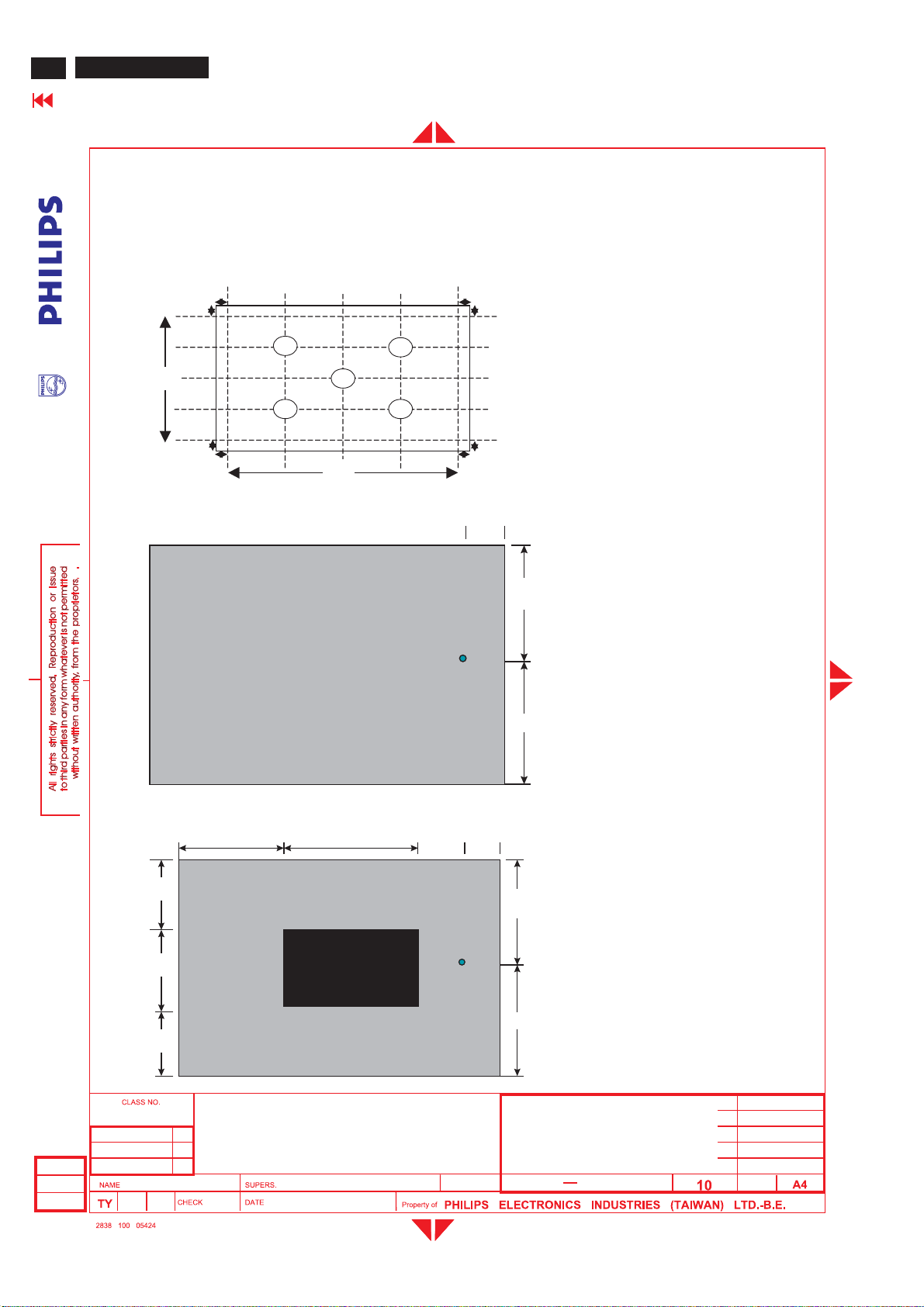
BDL3221 LCD/TV
98
Go to cover page
9.0 Ser vic eab ilit y
10.0 A ppendi ces
GENERAL PRODUCT SPECIFICATION(Continued)
The serviceability of this monitor should fulfill the requirements whic h are prescribed in UAW-0346 and must be
checked with the check list UAT-0361.
Fig 1:
Pattern 1: Brightness and Uniformity measure points
b
a
V
a
b
b
Pattern 2: Cross talk pattern
H/4
1
H/2 3H/
4
2
5
3
4
H
Gray lev el 184 (256 Gray level)
b
a
V/4
V/2
3V/
4
a
b
b
1/6
1/2
YA
1/2
Pattern 3: Cross talk Pattern
Center at Gr ay level 0 (B l ac k)
1/3 1/3
1/3
1/3
1/3
32 inch BDS WXGA TFT LCD Monitor/TV
TYPE : BDL3221V/00
BRAND : PHILIPS
2005-06-17
Freud Yu
2005-06-17
YB
32
1/6
1/2
1/2
8639 000 16304
590
27
Page 99
GENERAL PRODUCT SPECIFICATION(Continued)
Tabl e 1. WE model : West Europe TV preload Channels
BDL3221 LCD/TV
Go to cover page
99
PRGCH
0
1 AU37 590.25MHz 595.75MHz PALB(UK)Pure White
2 AU2 64.25MHz 69.75MHz PALB(UK) Circle Pattern
3
4
5
6
7
8
9
10
11
12
PRGCH
13
14
15
16
17
18
19
20
21
22
23
24
25
28
E7 189.25MHz 194.75MHz
G47 679.25MHz 684.75MHz
I23 487.25MHz 493.75MHz
E12 224.25MHz 229.75MHz
AU7 182.25MHz 187.75MHz
G68 847.25MHz 852.75MHz
AU9 196.25MHz 201.75MHz
AU10 209.25 MHz 214.75 MHz
AU0 46.25MHz 51.75MHz
AU2 64.25MHz 69.75MHz
AU5 102.25 MHz 107.75 MHz
AU5A 138.25MHz 143.75MHz
AU7 182.25MHz 187.75MHz
AU9 196.25MHz 201.75MHz
AU10 209.25MHz 214.75MHz
I23 487.25MHz 493.75MHz
G28 527.25MHz 532.75MHz
AU37 590.25MHz 595.75MHz
I40 623.25MHz 629.75MHz
CH44 655.25MHz 661.75MHz
I60 783.25MHz 789.75MHz
I66 831.25MHz 837.75MHz
K21 471.25 MHz 477.75 MHz
G28 527.25MHz 532.75MHz
Frequency Carriers
Video Sound
Frequency
Carrier s
TV System
TV System
PALB
(CCIR)
PALG
(CCIR)
PAL I
(UK)
PALB
(CCIR)
PALB
(UK)
PALG
(CCIR)
PALB
(UK)
PALB
(UK)
PALB
(UK)
PALB
(UK)
Patt er nPRG
PALB
(UK)
PALB
(UK)
PALB
(UK)
PALB
(UK)
PALB
(UK)
PAL I
(UK)
PALG
(CCIR)
PALG
(UK)
PAL I
(UK)
PALDK
(UK)
PAL I
(UK)
PAL I
(UK)
SECK1
(CCIR)
PALG
(UK)
Patt er n
Circle Pattern
Circle Pattern
Circle Pattern
Color Bar
Color Bar
100% White
Checkerboard
Crosshatch
Color Bar
Color Bar
Crosshatch
Color Bar
Pure White
Pure White
Circle Pattern
Circle Pattern
Circle Pattern
Circle Pattern
Color Bar
Color Bar
100% White
Checkerboard
Crosshatch
Color Bar
2005-06-17
Freud Yu
32 inch BDS WXGA TFT LCD Monitor/TV
TYPE : BDL3221V/00
BRAND:PHILIPS
32
2005-06-17
8639 000 16304
590
28
Page 100
100
BDL3221 LCD/TV
Go to cover page
Table 2 . NA FTA m o del :
US- Air broadcast channel
Broadcast
Channel
2 55.25 59.75 54-60
3 61.25 65.75 60-66
4 67.25 71.75 66-72
5 77.25 81.75 76-82
6 83.25 87.75 82-88
7 175.25 179.75 174-180
8 181.25 185.75 180-186
9 187.25 191.75 186-192
10 193.25 197.75 192-198
11 199.25 203.75 198-204
12 205.25 209.75 204-210
13 211.25 215.75 210-216
14 471.25 475.75 470-476
15 477.25 481.75 476-482
16 483.25 487.75 482-488
17 489.25 493.75 488-494
18 495.25 499.75 494-500
19 501.25 505.75 500-506
20 507.25 511.75 506-512
21 513.25 517.75 512-518
22 519.25 523.75 518-524
23 525.25 529.75 524-530
24 531.25 535.75 530-536
25 537.25 541.75 536-542
26 543.25 547.75 542-548
27 549.25 553.75 548-554
28 555.25 559.75 554-560
29 561.25 565.75 560-566
30 567.25 571.75 566-572
31 573.25 577.75 572-578
42 579.25 583.75 578-584
33 585.25 589.75 584-590
34 591.25 595.75 590-596
35 597.25 601.75 596-602
36 603.25 607.75 602-608
37 609.25 613.75 608-614
38 615.25 619.75 614-620
39 621.25 625.75 620-626
40 627.25 631.75 626-642
41 633.25 637.75 642-638
42 639.25 643.75 638-644
43 645.25 649.75 644-650
44 651.25 655.75 650-656
45 657.25 661.75 656-662
46 663.25 667.75 662-668
47 669.25 673.75 668-674
48 675.25 679.75 674-680
49 681.25 685.75 680-686
50 687.25 691.75 686-692
51 673.25 697.75 692-698
52 699.25 703.75 698-704
53 705.25 709.75 704-710
54 711.25 715.75 710-716
55 717.25 721.75 716-722
56 723.25 727.75 722-728
57 729.25 733.75 728-734
58 735.25 739.75 734-740
59 741.25 745.75 740-746
60 747.25 751.75 746-752
61 753.25 757.75 752-758
62 759.25 763.75 758-764
63 765.25 769.75 764-770
64 771.25 775.75 770-776
65 777.25 781.75 776-782
66 783.25 787.75 782-788
67 789.25 793.75 788-794
68 795.25 799.75 794-800
69 801.25 805.75 800-806
GENERAL PRODUCT SPECIFICATION(Continued)
Video Carrier (MHz) Audio Carrier
(MHz)
Range
(MHz)
2005-06-17
Freud Yu
32 inch BDS WXGA TFT LCD Monitor/TV
TYPE : BDL3221V/00
BRAND : PHILIPS
32
2005-06-17
8639 000 16304
590
29
 Loading...