

Philips bb159 DATASHEETS

DISCRETE SEMICONDUCTORS
DATA SH EET
lfpage
M3D049
BB159
UHF variable capacitance diode
Product specification
Supersedes data of 1996 May 03
1996 Oct 03
Philips Semiconductors Product specification
UHF variable capacitance diode BB159
FEATURES
• Excellent linearity
• Very small plastic SMD package
• C28: 2.1 pF; ratio 9
• Low series resistance.
APPLICATIONS
• Electronic tuning in UHF television
tuners
• VCO.
DESCRIPTION
The BB159 is a variable capacitance
diode, fabricated in planar
technology, and encapsulated in the
SOD323 very small plastic SMD
package.
The matched type, BB149 has the
same specification.
ELECTRICAL CHARACTERISTICS
T
=25°C; unless otherwise specified.
j
handbook, 4 columns
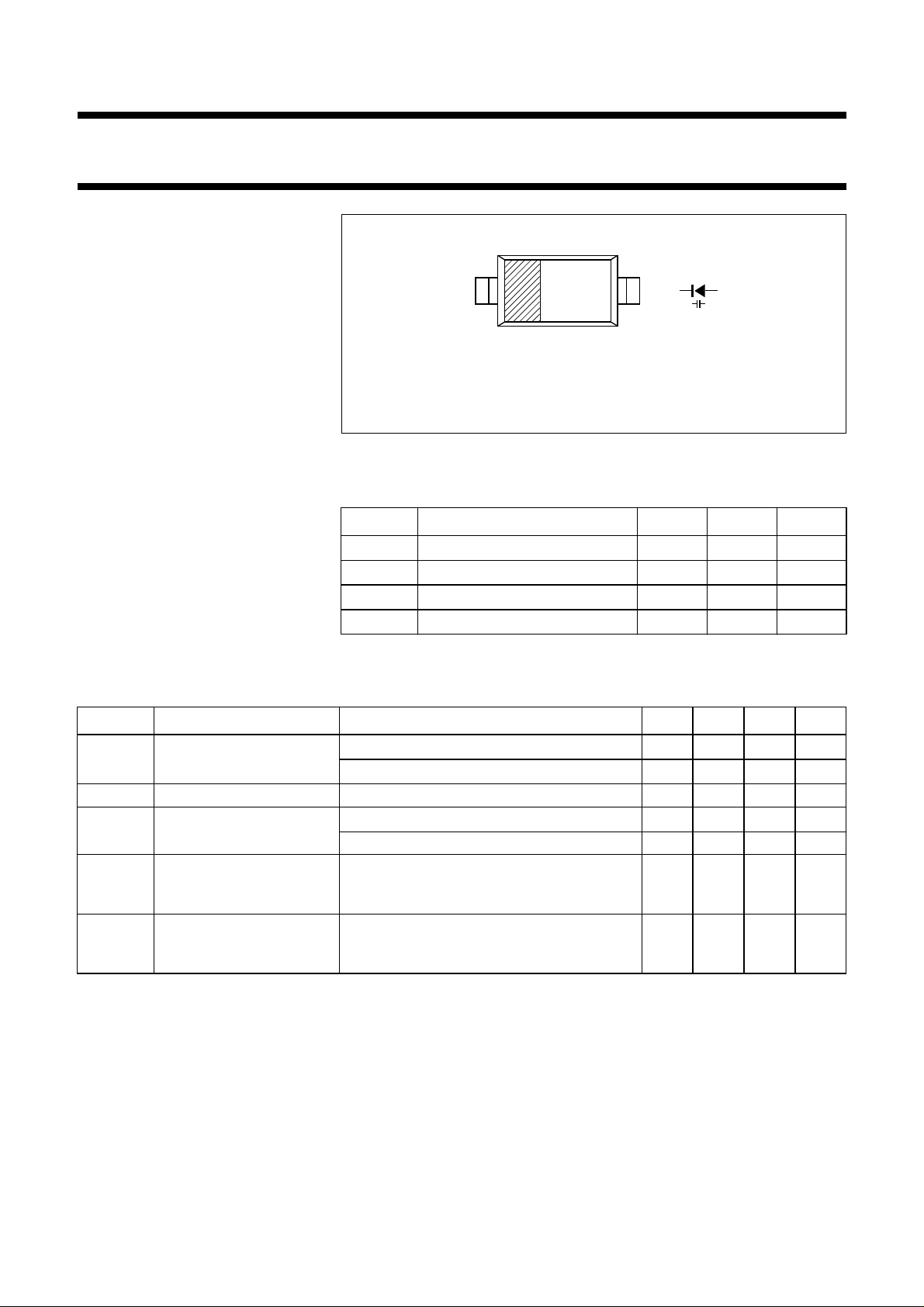
Marking code: PJ.
Cathode side indicated by a bar.
ka
MAM130
Fig.1 Simplified outline (SOD323) and symbol.
LIMITING VALUES
In accordance with the Absolute Maximum Rating System (IEC 134).
SYMBOL PARAMETER MIN. MAX. UNIT
V
R
I
F
T
stg
T
j
continuous reverse voltage
continuous forward current −
storage temperature
operating junction temperature
−
−55
−55
30 V
20 mA
+150 °C
+125 °C
SYMBOL PARAMETER CONDITIONS MIN. TYP. MAX. UNIT
I
R
r
s
C
d
C
d1V()
-------------------C
d28V()
C
d19V()
-------------------C
d28V()
reverse current VR= 30 V; see Fig.3 −−
= 30 V; Tj=85°C; see Fig.3 −−
V
R
10
200
diode series resistance f = 470 MHz; note 1 −−0.75 Ω
diode capacitance VR= 1 V; f = 1 MHz; see Figs 2 and 4
= 28 V; f = 1 MHz; see Figs 2 and 4 1.9 − 2.25 pF
V
R
18
−
19.5 pF
capacitance ratio f = 1 MHz 8.2 − 10
capacitance ratio f = 1 MHz 1.2 −−
nA
nA
Note
is the value at which Cd= 9 pF.
1. V
R
1996 Oct 03 2
 Loading...