

Philips AZ-7562 Service manual
SHARON PLATFORM 4
Technical specification ......................................................1-1
Connections and controls..................................................1-2
Feature overview...............................................................1-3
Accessories .......................................................................1-3
Safety warnings.................................................................1-4
Service hints
Repair positions ............................................................2-1
Service tools..................................................................2-1
Training material ...........................................................2-1
ESD protection equipment............................................2-1
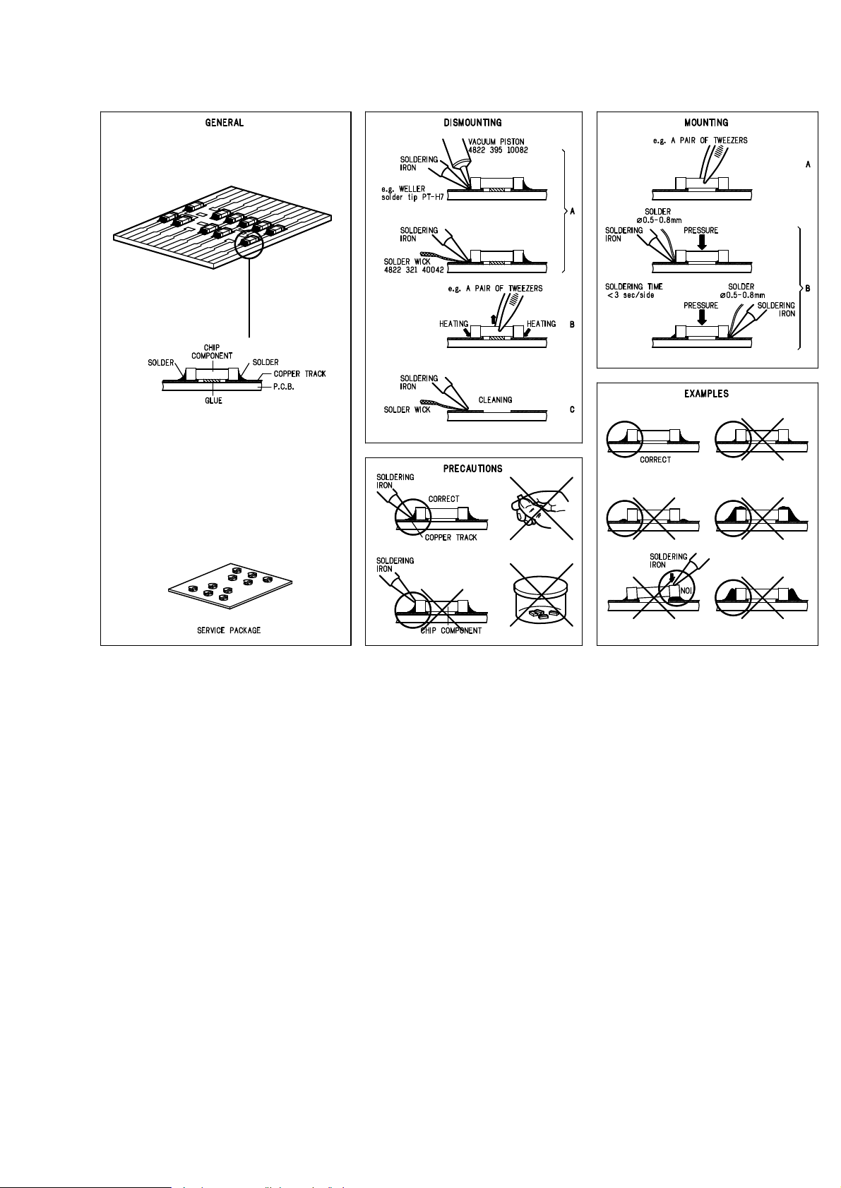
Handling chip components............................................2-2
Service test program .................................................2-3...2-4
Start-up procedure.............................................................2-5
Fault finding guide.....................................................2-5...2-9
Blockdiagram.....................................................................3-1
Pinning of ICs............................................................3-2...3-4
Circuit diagrams
Supply/Servodriver part.................................................4-1
Signal processing part...................................................4-2
Control part ...................................................................4-3
Audio part......................................................................4-4
Printed circuit board
Copperside view............................................................4-5
Componentside view.....................................................4-6
Exploded view ...................................................................5-1
Mechanical partslist...........................................................5-1
Electrical partslist ......................................................6-1...6-3
CS 46 427
AZ7562/00/05
© 4822 725 26007
Published by PW 9713 Service Audio Printed in The Netherlands Subject to modification
Portable compact disc player
PLAY
.
PAUSE
CLASS 1
LASER PRODUCT
AZ7565/00/05
AZ7566/17/17T
TABLE OF CONTENTS
©
Copyright 1997 Philips Consumer Electronics B.V. Eindhoven, The Netherlands
All rights reserved. No part of this publication may be reproduced, stored in a retrieval
system or transmitted, in any form or by any means, electronic, mechanical, photocopying,
or otherwise without the prior permission of Philips.
1-1
CS 46 428
TECHNICAL SPECIFICATION
General
Dimensions (WxHxD) : 134x30.5x154mm
Weight without batteries : 250g
Power supply modes
DC-in socket : 4.5-5.5V
Battery 2xLR6 : 1.8-3.6V
Accu-pack AY3360 (NiMH) : 1.8-3.6V
Accu-pack AY3361 (NiCd) : 1.8-3.6V
Battery lifetime
Battery empty detection
Battery weak level : 2.1V nom. ±150mV
Battery empty level : 1.9V nom. ±100mV
Charge circuit
Charge current : 300mA ±10%
Charge time for 80% : 4hrs nom.
Max. charge time (µP controlled) : 6hrs nom.
Temperature protection : 50°C ±5°C
Current consumption (DC-in=4.5V, excl. illumination)
Current consumption (Batt. supply=2.25V, excl. illumin.)
Shock resistance (ESA off)
+X/-X direction : >2.5G
+Y/-Y direction : >2.5G
+Z/-Z direction : >2.0G
Shock resistance by use of car base (ESA off)
+X/-X direction : >6G
+Y/-Y direction : >6G
+Z/-Z direction : >6G
Headphone out (measured with 16Ω load)
Max. output power (THD=10%) : 2x7mW (+1/-3dB)
Frequency response (1mW) : 20Hz-20kHz within 6dB
S/N ratio (unw.) : >80dB (83dB typ.)
S/N ratio (A-wght) : >85dB (88dB typ.)
THD+N (1kHz, 1mW) : <1% (0.2% typ.)
Channel crosstalk (1kHz, no load): <-50dB
Channel unbalance (-40dB) : <1dB
Volume attenuation (1kHz) : >80dB
Headphone out under CD-out conditions
(volume at maximum, load impedance 47kΩ)
Output level (1kHz, 0dB) : 680Vrms ±2dB
Frequency response : 20Hz-20kHz within 4dB
S/N ratio (unw.) : >85dB (90dB typ.)
S/N ratio (A-wght) : >90dB (95dB typ.)
THD+N (1kHz, 0dB) : <0.2% (0.05% typ.)
THD+N (1kHz, -20dB) : <0.3% (0.1% typ.)
Channel crosstalk (1kHz) : <-60dB (-70dB typ.)
Channel crosstalk (10kHz) : <-40dB (-50dB typ.)
Channel unbalance (1kHz, 0dB) : <0.5dB (0.2dB typ.)
Optical output (not on all versions)
Connection : 3.5mm optical fiber jack
Specification according to IEC958.
Laser
Output power : <5mW (3mW typ.)
Wavelength : 780nm
Measurement setup
Use Audio Signal disc SBC429 4822 397 30184
L
R
LEVEL METER
e.g. Sennheiser UPM550
with FF-filter
S/N and distortion meter
e.g. Sound Technology ST1700B
NOITAREPO NOITAREPO
NOITAREPO
NOITAREPO NOITAREPO FFOASE FFOASE
FFOASE
FFOASE FFOASE NOASE NOASE
NOASE
NOASE NOASE
edom-yalP
Am053<
.pytAm072
Am014<
.pytAm513
edom-pmuJ
Am086<
.pytAm064
Am086<
.pytAm075
yb-dnatS
)egrahcer.lcxe(
05< µA
01 µ .pytA
NOITAREPO NOITAREPO
NOITAREPO
NOITAREPO NOITAREPO FFOASE FFOASE
FFOASE
FFOASE FFOASE NOASE NOASE
NOASE
NOASE NOASE
edom-yalP
Am072<
.pytAm012
Am582<
.pytAm022
edom-pmuJ
Am086<
.pytAm584
Am086<
.pytAm525
yb-dnatS
)egrahcer.lcxe(
Am021<
.pytAm001
EPYTYRETTAB EPYTYRETTAB
EPYTYRETTAB
EPYTYRETTAB EPYTYRETTAB FFOASE FFOASE
FFOASE
FFOASE FFOASE NOASE NOASE
NOASE
NOASE NOASE
yrettabenilaklA
)6RLx2(
srh57.3>
.pytsrh5.5
srh57.2>
.pytsrh5.4
0633YAkcap-uccA
)hAm0021,HMiN(
srh0.3>
.pytsrh0.4
srh5.2>
.pytsrh5.3
1633YAkcap-uccA
)hAm007,dCiN(
srh8.1>
.pytsrh52.2
srh5.1>
.pytsrh0.2

DISPLAY. . . . . . . . . . . Window for showing the different playing modes, tracks and times
§ . . . . . . . . . . . . . . . . . Button for selecting the next music track or, if held down, for searching forward for a particular passage
on the CD
∞ . . . . . . . . . . . . . . . . . Button for selecting the previous music track or, if held down, for searching backward for a particular
passage on the CD
VOLUME. . . . . . . . . . . Control for adjusting the volume at the headphone output
HOLD / RESUME . . . . Switch for activating the HOLD function (blocking all buttons) and/or
RESUME function (resuming CD play)
MODE 0 . . . . . . . . . . . Button for selecting the different playing modes:
SHUFFLE
→SHUFFLE REPEAT ALL→REPEAT 1→REPEAT ALL→SCAN→off
PROG . . . . . . . . . . . . . Button for storing tracks in a program and for reviewing the program
DSP. . . . . . . . . . . . . . . Digital Sound Processing: Button for selecting the different sound settings at the headphone output:
ROCK→POP→CAR→INCREDIBLE SOUND→off
STOP 9 . . . . . . . . . . . . Button for stopping CD play, deleting various settings, switching off the CD player and activating
charging
OPEN . . . . . . . . . . . . . Slide control for opening the lid of the CD player
2; . . . . . . . . . . . . . . . . Button for starting and pausing CD play
ESA. . . . . . . . . . . . . . . Electronic Shock Absorption: Switch for activating the electronic buffer memory for an undisturbed
sound
REMOTE
p . . . . . . . . . Headphone and remote control socket (3.5mm)
Digital out (optical) . . For connecting the CD player to a Digital in (optical) socket in an amplifier or a digital recorder by means
of an optical cable
4,5 V DC . . . . . . . . . . . Socket for external power supply
Battery compartment for inserting batteries
Note: In case of power supply via the DC jack (mains adapter or cigarette lighter in the car) the display and the play button are
backlighted. In battery mode, the illumination is activated for 10 seconds after key operations.
1-2
CS 46 429
CONNECTIONS AND CONTROLS
DSP
PROGRAM
MODE
HOLD / RESUME
VOLUME
PREVIOUS
NEXT
DISPLAY
ESA
PLAY / PAUSE
OPEN
STOP
OPTICAL DIGITAL OUTPUT
HEADPH. / REMOTE
BATTERIES
6 V DC
1-3
CS 46 430
4MROFTALPNORAHSSEIROSSECCA
2657ZA 5657ZA 6657ZA
00/ 50/ 00/ 50/ 71/ T71/
A00/0613YA A00/0613YA
A00/0613YA
A00/0613YA A00/0613YA ROTPADACD/CA 752019122284 X X
A50/0613YA A50/0613YA
A50/0613YA
A50/0613YA A50/0613YA ROTPADACD/CA 762019122284 X X
A71/0613YA A71/0613YA
A71/0613YA
A71/0613YA A71/0613YA ROTPADACD/CA 862019122284 X X
00/0623YA 00/0623YA
00/0623YA
00/0623YA 00/0623YA HCUOP 893010062284 O O X X
00/0633YA 00/0633YA
00/0633YA
00/0633YA 00/0633YA HMiNKCAPYRETTAB 716018312284 O O X X
00/1633YA 00/1633YA
00/1633YA
00/1633YA 00/1633YA dCiNKCAPYRETTAB 516018312284 X X O O
00/1053YA 00/1053YA
00/1053YA
00/1053YA 00/1053YA ETTESSACROTPADARAC 950017932284 O O O O
71/1053YA 71/1053YA
71/1053YA
71/1053YA 71/1053YA ETTESSACROTPADARAC 850017932284 X X
00/5453YA 00/5453YA
00/5453YA
00/5453YA 00/5453YA RETREVNOCCD/CDRAC 330019122284 O O O O
71/5453YA 71/5453YA
71/5453YA
71/5453YA 71/5453YA RETREVNOCCD/CDRAC 130019122284 X X
00/3653YA 00/3653YA
00/3653YA
00/3653YA 00/3653YA ETALPROTPADARAC 690123622284 O O O O
71/3653YA 71/3653YA
71/3653YA
71/3653YA 71/3653YA ETALPROTPADARAC 101123622284 O O
00/2763YA 00/2763YA
00/2763YA
00/2763YA 00/2763YA ENOHPRAE 343012422284 X X
S00/2763YA S00/2763YA
S00/2763YA
S00/2763YA S00/2763YA ENOHPRAE 143012422284 X X
73/1863YA 73/1863YA
73/1863YA
73/1863YA 73/1863YA ENOHPDAEH 207012422284 X X
00/3673YA 00/3673YA
00/3673YA
00/3673YA 00/3673YA LORTNOCETOMERDCLDROC-NI 217018122284 O O X X
00/0683YA 00/0683YA
00/0683YA
00/0683YA 00/0683YA XOBREKAEPSEVITCA 315015442284 O O O O
71/0683YA 71/0683YA
71/0683YA
71/0683YA 71/0683YA XOBREKAEPSEVITCA 415015442284 O O
4643YA 4643YA
4643YA
4643YA 4643YA mm5.3(DROCIFIH → )gulp-L,hcnic 188110232284 O O O O O O
9501CBS 9501CBS
9501CBS
9501CBS 9501CBS mm5.3(DROCIFIH → )hcnic 206121232284 O O X X O O
0721CBS 0721CBS
0721CBS
0721CBS 0721CBS mm5.3(REBIFLACITPO → )kniLsoT 237261232284 O O
4MROFTALPNORAHSSERUTAEF
2657ZA 5657ZA 6657ZA
)ASE(NOITPROSBAKCOHSCINORTCELE .ces02 .ces02 .ces02
NOITCNUFEMUSER X X X
GNISSECORPDNUOSLATIGID X X X
KCAPYRETTABHMiNdnadCiNNOITCNUFEGRAHCER X X X
NOITANIMULLIDCL X X X
NOITANIMULLIYEK-YALP – – X
DERAPERPLORTNOCETOMERDROC X X X
)lacitpo(TUPTUOLATIGID – X –
X....supplied with the set, O....optional available
1-4
CS 46 431
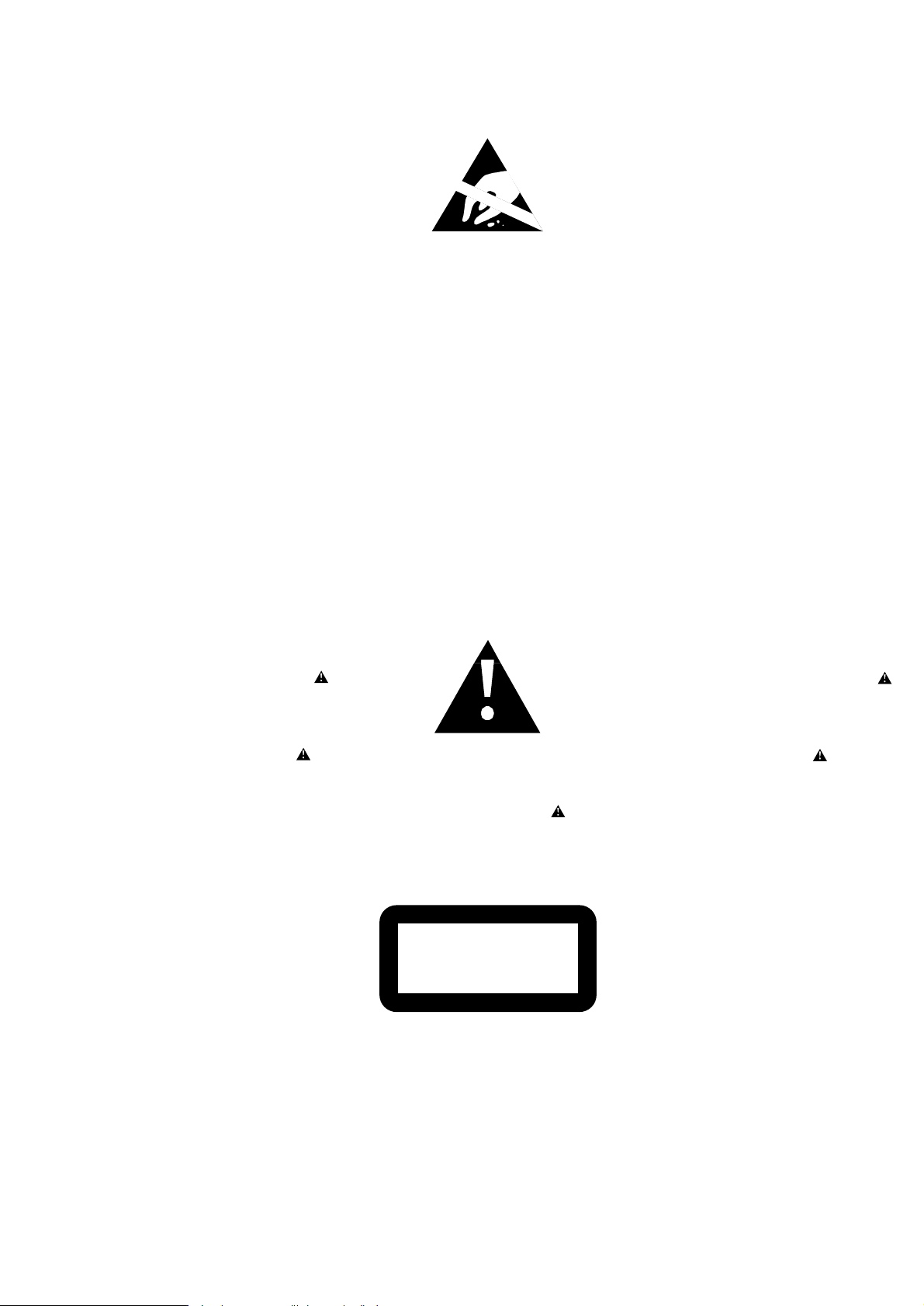
© WARNING
All ICs and many other semiconductors are susceptible to
electrostatic discharges (ESD). Careless handling during
repair can reduce life drastically.
When repairing, make sure that you are connected with the
same potential as the mass of the set via a wristband with
resistance. Keep components and tools at this potential.
f ATTENTION
Tous les IC et beaucoup d´autres semi-conducteurs sont
sensibles aux décharges statiques (ESD). Leur longévite
pourrait être considérablement écourtée par le fait qu´aucune
précaution nést prise à leur manipulation.
Lors de réparations, s´assurer de bien être relié au même
potentiel que la masse de l´appareil et enfileer le bracelet
serti d´une résistance de sécurité.
Veiller à ce que les composants ainsi que les outils que l´on
utilise soient également à ce potentiel.
d WARNUNG
Alle ICs und viele andere Halbleiter sind empfindlich
gegenüber elektrostatischen Entladungen (ESD).
Unsorgfältige Behandlung im Reparaturfall kann die
Lebensdauer drastisch reduzieren.
Sorgen Sie dafür, daß sie im Reparaturfall über ein Pulsarmband mit Widerstand mit dem Massepotential des
Gerätes verbunden sind.
Halten Sie Bauteile und Hilfsmittel ebenfalls auf diesem
Potential.
ñ WAARSCHUWING
Alle IC´s en vele andere halfgeleiders zijn gevoelig voor
electrostatische ontladingen (ESD).
Onzorgvuldig behandelen tijdens reparatie kan de levensduur
drastisch doen vermindern. Zorg ervoor dat u tijdens reparatie
via een polsband met weerstand verbonden bent met hetzelfde
potentiaal als de massa van het apparaat.
Houd componenten en hulpmiddelen ook op ditzelfde potentiaal.
i AVVERTIMENTO
Tutti IC e parecchi semi-conduttori sono sensibili alle scariche
statiche (ESD).
La loro longevità potrebbe essere fortemente ridatta in caso di
non osservazione della più grande cauzione alla loro
manipolazione. Durante le riparationi occorre quindi essere
collegato allo stesso potenziale che quello della massa
delápparecchio tramite un braccialetto a resistenza.
Assicurarsi che i componenti e anche gli utensili con quali si
lavora siano anche a questo potenziale.
©
Safety regulations require that the set be restored to its
original condition and that parts which are identical with
those specified be used.
Safety components are marked by the symbol
i
Le norme di sicurezza estigono che l´apparecchio venga
rimesso nelle condizioni originali e che siano utilizzati i
pezzi di ricambiago identici a quelli specificati.
Componenty di sicurezza sono marcati con
ñ
Veiligheidsbepalingen vereisen, dat het apparaat in zijn
oorspronkeliijke toestand wordt teruggebracht en dat
onderdelen, identiek aan de gespecificeerde, worden toegepast.
De Veiligheidsonderdelen zijn aangeduid met het symbool
s Varning !
Osynlig laserstrålning när apparaten är öppnad och
spärren är urkopplad. Betrakta ej strålen.
∂ Advarsel !
Usynlig laserstråling ved åbning når sikkerhedsafbrydere
er ude af funktion. Undgå udsaettelse for stråling.
ß Varoitus !
Avatussa laitteessa ja suojalukituksen ohitettaessa olet alttiina
näkymättömälle laserisäteilylle. Älä katso säteeseen !
f
"Pour votre sécurite, ces documents doivent être utilisés par
des spécialistes agréés, seuls habilités à réparer votre
appareil en panne".
ESD
SAFETY
d
Bei jeder Reparatur sind die geltenden Sicherheitsvorschriften zu beachten. Der Originalzustand des Gerätes
darf nicht verändert werden. Für Reparaturen sind Originalersatzteile zu verwenden.
Sicherheitsbauteile sind durch das Symbol markiert.
f
Les normes de sécurité exigent que l`appareil soit remis
à l`état d`origine et que soient utilisées les pièces de
rechange identiques à celles spécifiées.
Les composants de sécurité sont marqués
CLASS 1
LASER PRODUCT
©
DANGER: Invisible laser radiation when open.
©
After servicing and before returning the set to customer
perform a leakage current measurement test from all
exposed metal parts to earth ground, to assure no
shock hazard exists.
The leakage current must not exceed 0.5mA.
AVOID DIRECT EXPOSURE TO BEAM.
©
AVAILABLE ESD PROTECTION EQUIPMENT :
anti-static table mat large 1200x650x1.25mm 4822 466 10953
small 600x650x1.25mm 4822 466 10958
anti-static wristband 4822 395 10223
connection box (3 press stud connections, 1MΩ) 4822 320 11307
extendible cable (2m, 2MΩ, to connect wristband to connection box) 4822 320 11305
connecting cable (3m, 2MΩ, to connect table mat to connection box) 4822 320 11306
earth cable (1MΩ, to connect any product to mat or to connection box) 4822 320 11308
KIT ESD3 (combining all 6 prior products - small table mat) 4822 310 10671
wristband tester 4822 344 13999
SAFETY WARNINGS
2-1
CS 46 432
SERVICE HINTS
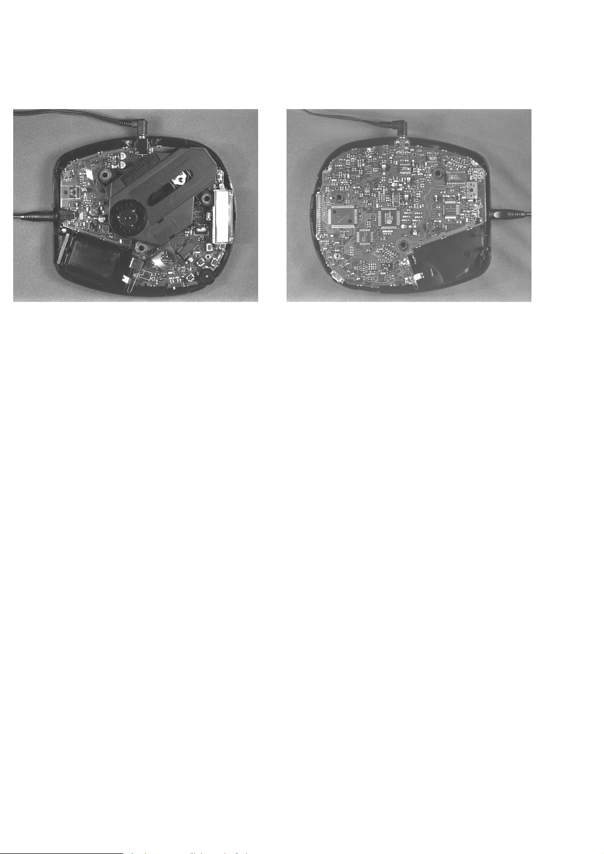
REPAIR POSITION COPPERSIDE
To get access to the componentside of the
printed circuit board proceed as follows:
1. Disconnect DC-cable and headphone
2. Remove bottom screws
(remember hidden screw in battery compartment)
3. Open the CD-door
4. Lift the top-cabinet
5. Close the door-switch (e.g. paper-clip)
6. Supply the unit via external DC-socket
To get access to the copperside of the
printed circuit board proceed as follows:
1. Disconnect DC-cable and headphone
2. Remove bottom screws
(remember hidden screw in battery compartment)
3. Open the CD-door
4. Lift the top-cabinet
5. Take the printed circuit board/drive unit out of the bottom
(take care of battery springs)
6. Position printed circuit board/drive unit into top-cabinet
7. Supply the unit via external DC-socket
SERVICE TOOLS
Audio signal disc SBC429 4822 397 30184
Playability test disc SBC444 4822 397 30245
Test disc 5 (disc without errors) + Test disc 5A (disc with dropout errors,
black spots and fingerprints) SBC426/SBC426A 4822 397 30096
TRAINING MATERIAL
Portable CD 1994 – Principles of Electronic Shock Absorption System ESA,
Key components 1994, Remote control system 4822 725 24941
Portable CD 1996 – Key components 1996, Battery charging, DC/DC-converter 4822 725 24986
ESD PROTECTION EQUIPMENT
Anti-static table mat large 1200x650x1.25mm 4822 466 10953
small 600x650x1.25mm 4822 466 10958
Anti-static wristband 4822 395 10223
Connection box (3 press stud connections, 1MΩ) 4822 320 11307
Extendible cable (2m, 2MΩ, to connect wristband to connection box) 4822 320 11305
Connecting cable (3m, 2MΩ, to connect table mat to connection box) 4822 320 11306
Earth cable (1MΩ, to connect any product to mat or to connection box) 4822 320 11308
KIT ESD3 (combining all 6 prior products - small table mat) 4822 310 10671
Wristband tester 4822 344 13999
REPAIR POSITION COMPONENTSIDE
The unit is now in a proper working position and can be turned in all directions necessary to get access for measurements.
2-2
CS 46 433
HANDLING CHIP COMPONENTS

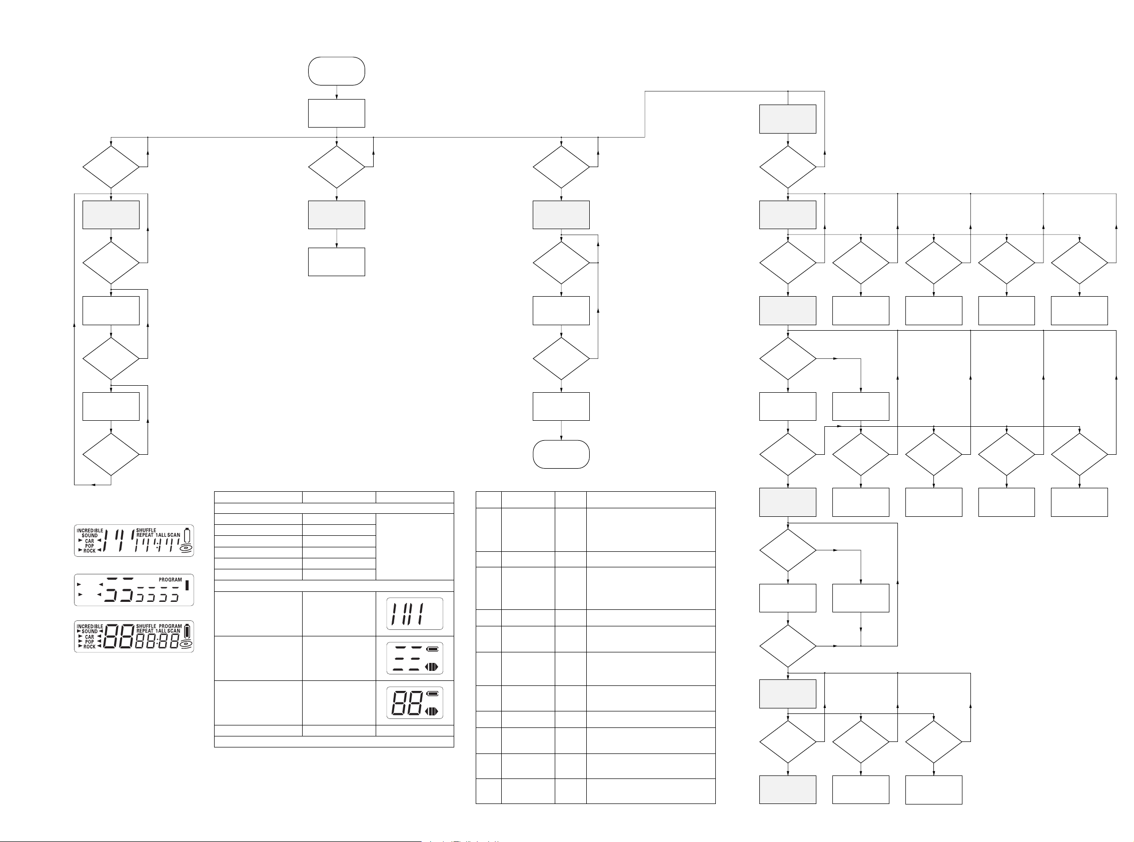
SERVICE TEST PROGRAM
1. PRELIMINARY SETUP
• To enter the service test program hold the keys “PROGRAM”
and “STOP” depressed while turning POWER ON.
• The display shows the software-version of the built-in
microprocessor (e.g. “
90S”).
• The program is now in the main menu – various tests can be
entered by pressing the corresponding buttons (see flow chart
or detailed description of test programs below).
2. DISPLAY TEST
Purpose: Check the internal display driver of the µP and the
display segments.
• To enter the display test start service test program and press
the “NEXT” button.
• The display shows test pattern 1. Three more test patterns are
available.
• To jump to the next pattern press the “PLAY” button.
• To exit the display test and return to the main menu press the
“STOP” button.
3. KEY & REMOTE CONTROL TEST
Purpose: Check operation of keys and remote control.
• To enter the key & remote control test start service test
program and press the “MODE” button.
• The display shows “--”.
• Press keys on the set resp. the remote control and check the
corresponding key codes on the display of the CD-player resp.
the test patterns on the display of the remote control. Codes
and patterns can be found in table 1 (see flow chart).
• To exit the key & remote control test and return to the main
menu press the “STOP” button.
4. PLAYBACK TEST WITH ERROR ANALYSIS
Purpose: Analyse errors that occur during playback.
• To enter the playback test start service test program and press
the “DSP” button. Note that the playback test can only be
entered if the CD-door is closed.
• The set now reads the TOC and switches to stand-by.
• Press the “PLAY” button to start the error analysis.
As long as the playback is free of errors the display shows track
and time information as in normal play-mode. In case of an error
a corresponding error code will be displayed. The meaning of
this error code can be found in table 2 (see flow chart).
Note:
Errors can either be
“fatal”
or
“non fatal”
. Fatal errors
always stop the playback, non fatal errors only cause a
short interruption of the music. Fatal errors are displayed
as long as the set is connected to the power source, non
fatal errors are displayed till a new error occurs or a
button is pressed.
• To stop the playback test disconnect the set from the power
source.
5. IC-CHECK
Purpose: Check communication between µP ↔ CD7 and
µP ↔ NPC (DRAM controller).
• To enter the IC-check start service test program and press the
“PLAY” button.
• The display shows “C
xny
”. “Cx” indicates result of CD7-check;
“n
y
” indicates result of NPC-check.
x,y
= ”1” means that the
test has been passed successfully;
x,y
= ”0” specifies an error
during communication.
• To enter the servo test press the “PLAY” button, to exit the ICcheck and return to the main menu press the “STOP” button.
6. SERVO TEST
Purpose: Check door- and inner-switch, movement of slide and
acceleration of discmotor.
• To enter the servo test start service test program and press the
“PLAY” button.
• The display shows “S
xy
”. “x” indicates state of door-switch; “y”
indicates state of inner-switch.
x,y
= “1” means switch is open.
• To move slide outside hold the “NEXT” button depressed.
• To move slide inside hold the “PREV” button depressed.
• To accelerate the discmotor clockwise hold the “MODE” button
depressed.
• To accelerate the discmotor counter-clockwise hold the “DSP”
button depressed.
• To enter the focus test press the “PLAY” button, to exit the
servo test and return to the main menu press the “STOP”
button.
7. FOCUS TEST
Purpose: Check movement of lens and operation of focus servo.
• The focus servo loop is switched on and the set starts
searching the focus. If the focus is OK the display shows “ F”,
else “-F”.
• When the disc is turned manually “focus noise” is audible.
• To move slide outside hold the “NEXT” button depressed.
• To move slide inside hold the “PREV” button depressed.
• To accelerate the discmotor clockwise hold the “MODE” button
depressed.
• To accelerate the discmotor counter-clockwise hold the “DSP”
button depressed.
• In case the focus is OK the discmotor test can be entered by
pressing the “PLAY” button, to exit the focus test and return to
the main menu press the “STOP” button.
8. DISCMOTOR TEST
Purpose: Check speed regulation of discmotor.
• The speed regulation is switched on and the discmotor starts
rotating. If the speed reaches 75% of the nom. speed the
display shows “ d”, else “-d”.
Note:
During this test the µP displays the speed-flag of the CD7.
As this IC can only monitor a small range of speed
deviation the displayed information is not very reliable. In
case of doubt check disc motor control circuit.
• In case the disc speed is OK the radial test can be entered by
pressing the “PLAY” button, to exit the discmotor test and
return to the main menu press the “STOP” button.
9. RADIAL TEST
Purpose: Check if radial loop locks and an audio signal is
output.
• The display shows “rd”.
• The radial servo loop is switched on, mute is released and an
audio signal is audible.
• To jump 10 tracks outside press the “NEXT” button.
• To jump 10 tracks inside press the “PREV” button.
• To enter the error correction analysis press the “PLAY” button,
to exit the radial test and return to the main menu press the
“STOP” button.
10. ERROR CORRECTION ANALYSIS
Purpose: Check the error status of the CD7 in double speed
mode (measurement of block error rate, number of
interpolations, a.s.o).
• The display shows “H”.
• The disc turns at double speed, mute is released and music is
audible with twice the normal speed.
Note:
This test program is used for statistical analysis of the
error correction of the CD7. As the test requires additional
hard- and software it can´t be carried out at “normal”
repair shops.
• To exit the error correction analysis and return to the main
menu press the “STOP” button.
2-3
CS 46 434
2-42-4
CS 46 435
table1 – key & RC-test
DISPLAY CORD RC
no change
no change
DISPLAY SET
01
02
03
04
05
07
rC 01
rC 03
rC 05
rC 06
KEYS OF SET
PLAY
MODE
NEXT
DSP
PREVIOUS
PROGRAM
KEYS OF CORD-REMOTE CONTROL
(not on all versions)
PLAY
NEXT
PREVIOUS
STOP
Press “STOP” on the CD-player to exit the key & RC-test.
PRELIMINARY
SETUP
EXIT
SERVICE TEST
PROGRAM
Display shows
software-version
(e.g. “90
S”)
DISPLA Y TEST
Display shows
test pattern 1
KEY & RC-TEST
Display shows
“--”
SERVO TEST
Display shows
“S
xy
”
To enter service test program hold
“PROGRAM” & “STOP”-button depressed,
while turning POWER ON.
Remark: Playback test can only
be entered if CD-door
is closed!
IC-CHECK
Display shows
“C
x
ny”
FOCUS TEST
1)
CUE-MODE
Track servo jumps
16 tracks forward
RADIAL TEST
Display shows
“rd”
STATUS OF
ERROR CORR.
Display shows "H"
“NEXT”
pressed?
“MODE”
pressed?
“DSP”
pressed?
“PLAY”
pressed?
“PLAY”
pressed?
Error during
playback?
FOCUS
found?
“PLAY”
pressed?
“PLAY”
pressed?
“PLAY”
pressed?
“NEXT”
pressed?
REVIEW-MODE
Track servo jumps
16 tracks backw.
“PREV”
pressed?
Disc motor
at nom.speed
?
Display shows
“F”
Fatal error?
Display shows
error-code
PLAYBACK
TEST
DISC MOT. TEST
Disc motor is on
Display shows
“-F”
Slide moves
outside
Slide moves
inside
Display shows
“d”
Display shows
“-d”
“NEXT”
pressed?
“PLAY”
pressed?
“PLAY”
pressed?
“PLAY”
pressed?
Display shows
test pattern 3
Display shows
test pattern 2
“PREV”
pressed?
“MODE”
pressed?
“DSP”
pressed?
Stop playback
Press keys
and check display
acc. to table1
MAIN MENU
N
Y
N
Y
N
Y
N
Y
N
Y
N
Y
N
Y
N
Y
N
Y
N
Y
N
Y
N
Y
N
Y
N
Y
N
Y
N
Y
N
Y
N
Y
N
Y
N
Y
N
Y
CODE
E 1001
E 1002
E 1003
E 1004
E 1005
E 1011
E 1012
E 1013
E 1014
E 1018
E 1019
ERROR
sledge out error
focus error
radial error
subcode error
DRAM filling
error
sledge in error
focus search
error
fatal radial error
fatal subcode
error
motor N1 error
motor N2 error
TYPE
non fatal
non fatal
non fatal
non fatal
non fatal
fatal
fatal
fatal
fatal
fatal
fatal
CAUSE
The sledge did not come out of it´s
inner position (inner switch of CDM12
doesn´t open) before 240ms have
passed by.
Focus point lost.
The offtrack values of CD7 don´t
decrease properly when jumping tracks,
or CD7 indicates offtrack while radial
tracking is switched on.
No valid subcode information for 250ms.
The DRAM controller was not able to
connect two consecutive audio frames.
The sledge did not reach it´s inner pos.
(inner switch of CDM12 doesn´t close)
before 6 seconds have passed by.
The focus point could not be found
inbetween 4 seconds.
Radial error occured 15 times.
No valid subcode information for
3.5 seconds.
The disc didn´t reach 75% of the
nom. single speed inbetween 4.5 sec.
The disc didn´t reach 75% of the
nom. double speed inbetween 4.5 sec.
test pattern 1
table2 – playback error analysis
test pattern 2
test pattern 3
Disc motor turns
clockwise
(accelerate)
Disc motor turns
counter-clockwise
(brake)
Slide moves
outside
Slide moves
inside
“NEXT”
pressed?
“PREV”
pressed?
“MODE”
pressed?
“DSP”
pressed?
N
Y
N
Y
N
Y
N
Y
Disc motor turns
clockwise
(accelerate)
Disc motor turns
counter-clockwise
(brake)
C
x
....result of CD7-check
n
y
....result of NPC-check
x,y
= “1” means test OK
x
....state of door switch
y
....state of inner switch
x,y
= “1” means switch open
1)
ATTENTION: LASER IS SWITCHED ON
→ AVOID DIRECT EXPOSURE TO BEAM !!
FLOW CHART
 Loading...