

Philips AZ-5741 Service Manual
DVD 4W CD Soundmachine
AZ5741/55/93/98/79
CONTENTS
Technical Specification......................................................................1-1..1-5
Safety Instruction......................................................................................2-1
Version Variation.......................................................................................2-2
Block diagram...........................................................................................3-1
Wiring diagram ........................................................................................3-2
Circuit Diagram
All PCB board......................................................................................4-1 4-5
Layout diagram
All PCB Layout....................................................................................5-1 5-6
Explode Drawing.......................................................................................6-1
©
Copyright 2012 Philips Consumer Electronics B.V. Eindhoven, The Netherlands
All rights reserved. No part of this publication may be reproduced, stored in a retrieval
system or transmitted, in any form or by any means, electronic, mechanical, photocopying,
or otherwise without the prior permission of Philips.
Published by LZ 1209 Subject to modification
Version 1.1
3141 785 37561
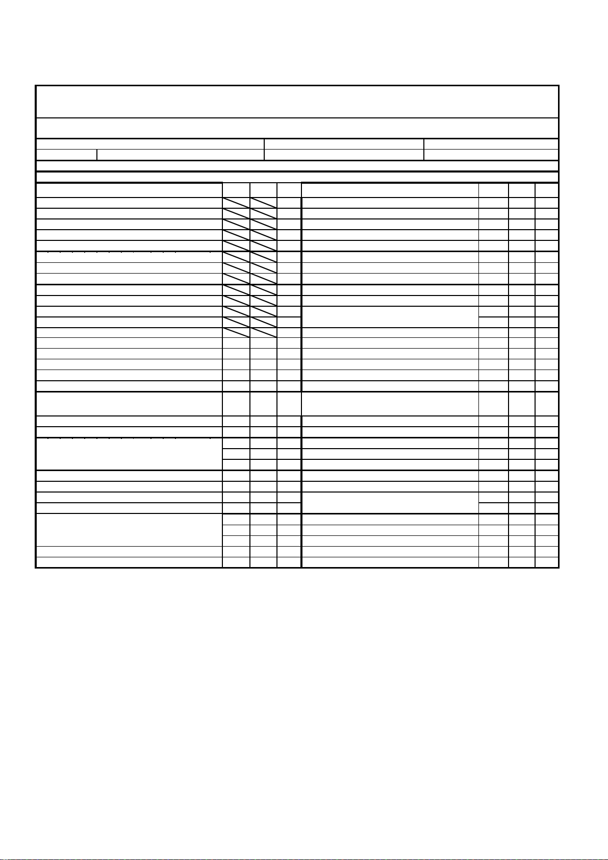
TECHNICAL SPECIFICATION
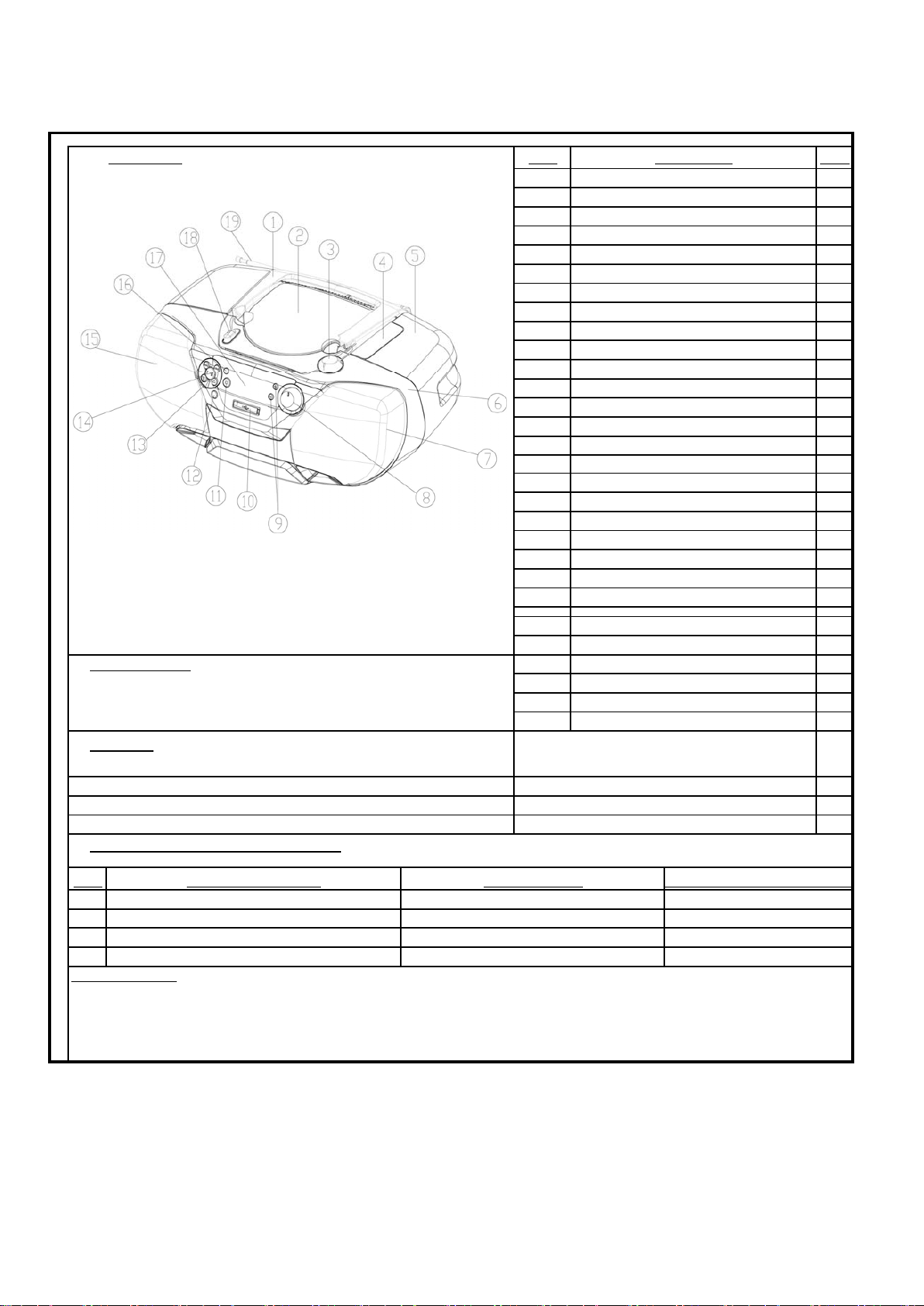
SPEAKER GRILL(LEFT)
16
14
15
11 STOP KNOB
9
12
7
FRONT CABINET
Battery location
17 DISPLAY LENS
FUNCTION MODE KNOB 18
Pos.
TUNER LENS
MODE KNOB
KNOB RING
5
13
TOP CABINET
HANDLE
TUNING KNOB
ZOOM KNOB
VOL KNOB
Description Pos. Description
2 CD DOOR
1
19
IR SENSOR
3
6
8
10
FUNCTION CONTROL
SPEAKER GRILL(RIGHT)
USB COVER
4
ANTENNA
44
ACCESSORIES :
(1) Remote Control
(3) AV Cable
45
27 AV Out Jack
28 Headphone Jack
29 AC JACK
(2) AC Cord
Units in Dealercarton: 1 set
Weight (including packing): 3.98 kg
Weight (excluding packing and batteries): 3.05 kg
Unit in Mastercarton: N/A
43
Material: ABS/HIPS
Finishing:
Dimensions with Boxes 390 x 240 x 160mm (LxWxH)
CABINET
NA
Dimensions without Boxes: 454 x 275 x 200 mm (LxWxH)
42
Connector type
INTERCONNECTION POSSIBILITIES
lectrical data (input or R.O.
P
Pos. Connection/Function
1-1
TECHNICAL SPECIFICATION
GENERAL DESCRIPTION
(Per Channel 2W )
LIFE TIME(according to XUT-0026)
5 Years
PERFORMANCE CLASSES
Class Tuner Supply+Amplifier Loudspeaker Boxes Cassette Recorde
r
DVD/CD
IX X X
II X
III
SAFETY requirements
See Sh-190-05
RADIATION/IMMUNITY requirements(EMC)
See Sh-190-05
CLIMATIC requirements(according to UAN-D1590)
ALL climates : ʾˈк till +35 к
MODERATE climates :N
A
till к
POWER SUPPLY MAINS (AC)
Version /98 /93 /55
AC Voltage 115V /230V ± 10% 220V± 15% 115V /230V ± 10%
V
oltage Selection Yes NA Yes
Frequency 60 /50 Hz 50 Hz 60 /50 Hz
POWER CONSUMPTION
AZ5741/98/93/55
Operation (1/8 Prated,Nom AC input) 12W
MAX POWER CONSUMPTION 18W
DVD PLAYER/ Digital Tuner /CASSETTE REC
O
Standb
y
İ2
W
Q and R according to Product Division Rules
Quality : 0.4% (major) 1.5%(minor)
Reliability : 2.0% (C42)
Tested according to General Test Instruction UAN-D1591
Measured According to UAN-L1059 unless otherwise stated
All
not mentione
d dat
e, please referto
PQR XUW-0010-JUNE 2001
1-2
1-3
TECHNICAL DESCRIPTION
Per Channel 2W
ELECTRICAL DAT
A
IS: NA Playable Disc:DVD Single/Double Layer CD/MP3/WMA VCD1.1/2.1
MAX: NA SVCD Kodak Photo CD
VEC: NA Video Output: Composite Output 1VPP 75ohm
Level Difference: ±3 dB
Tuner: FM 67.5 kHz,
Tape: NA
Line Output: 1-2v RMS 10K ohm
Source Difference: '+/-3 dB
Channel Difference: ±3 dB
Hum (Volume Maximum Vol-20dB): 200 nW
Residual Noise (Volume Minimum):
Lim: 0.06 ȝW
Channel Seperation: Shock sens.: >3g
40dB at 1KHz /35dB at 16KHz /30 dB at 20KHz
signal to noise ratio : 65
B
A
OUTPUT POWER(8ohm Loading)
Mains Operation : 2W (NORMAL Per Channel) At cold condition with 10%THD 1KHz AC 230V/50Hz (or 127V/60Hz)
2.3W(LIMIT)
Frequency Response 100Hz ~ 16KHz within +0.5/–1.0dB (@ REF output )
LOUDSPEAKER(BOXES)
Rated Impeddance
Left/Right: 8ȍ @ 100 Hz ~ 20kHz
Matrix: NA
REMARKS
(*1) Deviations from PQR (FWD831).
TECHNICAL SPECIFICATION
1-4
TECHNICAL DESCRIPTION
GENERAL PART
WAVE Range TOLERANCES
FM 87.00~108.50 MHz -/+0.5 ~ -/+0.5MHZ
ELECTRICAL DAT
A
TAPE Nom limit unit FM Nom limit unit
-3dB Limiting Point :
AM SUPRESION (60 INPUT) :
Distortion(RF 1 mV, Freq.Dev.75kHz) :
IF :
S/N 26dB Quieting sens.AC
ImageRejection :
Audio Fidelity, Cent.-6dB (-50us100TO 10kH
Z
Large singnal handling
Hum (at Min VOL)
10% Distortion Power 98MHZ
FM S/N Ratio(A weighted) Mono input 68dBf
Channel unbalance 250H
Z to 6300HZ
mv
dB
1
dB
Channel separation (1kHz) dB
dB
dB
If Rejection 50
Nom
CD
dB
10.7
122116
1.3
dB
AFC hold range (60dB INPUT -3dB)
W
λ
KHZ
M
HZ
W
%
dBuv
dB
dB
Nw
TAPE MAX OUT POWER
DISTORTION λ
REC DISTORTION ( DC BIAS )
Hum&Noise
Playback S/N Ratio (Unweighted)-T112
Channel sepearation(PB only)-T141 1KHz
ERASE RATIO
TAPE SPEED
REC S/N RATIO(A weighted)
Rec separation
channel balance
unit
ı w
limit
dB
dB
H
Z
λ
λ
dB
dB
dB
dB
REC Playback Frequency Response(125-6.3kHz
)
Chanel output diff 0
Max out power 2
WOW &FLUTTER
±3dB dB
100HZ 0 ±3dB dB
dB
˅˃
ˆ
˅˃
±0.1
116
45
0
350
Љ˅
0.9
4555
15
25
2
21
±0
˅˄
50-60
0
±3
18
±3
108
±3dB
MIN NOISE 1
16KHZ
0
MAX HUM &NOISE 1 5
THD 10% power output 1.2
FREQUENCY RESPONSE 1KHZ
0
λ
dB
dB
50 ı dB
10KHZ 35 ı dB
mV
Nom Distortion 0.5 ˄
100HZ 35
T.H .D +NOISE (1KHZ.0dB) 1 0.9
2 mV
S/N RATIO 60 ı dB
λ
ı dB
ı w
CHANEEL SEPARATION 1
K
TECHNICAL SPECIFICATION
TECHNICAL SPECIFICATION
Description External DAC
DVD ME
C
H:
A
AI-
313(S
F-HD87
0)
output register
Channel Unbalance <±2dB ( Vol 0 ~ -50dB )
Frequency Response(+0.5/-1.0dB) 20Hz~20kHz
Signal to Noise Ratio(A-weighted) 70dBA Lim 65 dBA(at -20dBFS)
THD Noise(20 ~20,000Hz) 0.5%(Lim 2%)
(1kHz) 0.1% at -20dBFS
Outband Attentuation 35dB
Channel Separation 1K 40dB (Lim.30dB)
16K 35dB(Lim.25dB)
20K 30dB(Lim.25dB)
Emphasls(switched automatically by CD 10) 15 / 50ȝs
Remarks:
(*1) Deviation from PQR (XUW-0010 June 2001)
Video Performance
Description NTSC PAL
Amplitude output 1.0Vpp(+10/-10%) 1.0Vpp(+10/-10%)
White bar 714mVpp(+10/-10%) 700mVpp(±10%)
Sync amplitude 286mVpp(±40mV) 300mVpp(+30/-50mV)
Burst amplitude 286mVpp(±40mV) 300mVpp(+30/-50mV)
Burst/Chroma ratio ±5% ±5%
S/N luminance
Њ48dB Њ48dB
S/N chroma
A
M:Њ58dB/PM:Њ51dB
A
M:Њ51dB/PM:Њ46dB
Video bandwidth 6MHz(-5dB) 6MHz(-7dB)
Chroma subcanics frequency fsc=3.579545Mhz(±50ppm) fsc=4.433618Mhz(±50ppm)
Chroma/Luminance delay
Љ80ns Љ80ns
Subcanics locked/unlocked Locked locked
Mp3 performance
SANYO
description
Bit rates 32K-320Kps
Sampling rates(MPEG-1 Layer 3) 32kHz/44.1KHZ/48kHz
Joliet (8 character OSD display)
Windows XP
UDF basic (close format)
Mp3 multisession Directory resting Max 8 level, Max directory 32
Display filename/ID3
255 folders/999songs
1-5
2.0 SAFTETY INSTRUCTIONS
WARNING
GB
All ICs and many other semi-conductors are
susceptible to electrostatic discharges (ESD).
Careless handling during repair can reduce life
drastically.
When repairing, make sure that you are
connected with the same potential as the mass
of the set via a wrist wrap with resistance.
Keep components and tools also at this
potential.
F
ATTENTION
Tous les IC et beaucoup d’autres
semi-conducteurs sont sensibles aux
décharges statiques (ESD).
Leur longévité pourrait être considérablement
écourtée par le fait qu’aucune précaution n’est
prise à leur manipulation.
Lors de réparations, s’assurer de bien être relié
au même potentiel que la masse de l’appareil et
enfiler le bracelet serti d’une résistance de
sécurité.
Veiller à ce que les composants ainsi que les
outils que l’on utilise soient également à ce
potentiel.
2-2
ESD
D
WARNUNG
Alle ICs und viele andere Halbleiter sind
empfindlich gegenüber elektrostatischen
Entladungen (ESD).
Unsorgfältige Behandlung im Reparaturfall kan
die Lebensdauer drastisch reduzieren.
Veranlassen Sie, dass Sie im Reparaturfall über
ein Pulsarmband mit Widerstand verbunden
sind mit dem gleichen Potential wie die Masse
des Gerätes.
Bauteile und Hilfsmittel auch auf dieses gleiche
Potential halten.
WAARSCHUWING
NL
Alle IC’s en vele andere halfgeleiders zijn
gevoelig voor electrostatische ontladingen
(ESD).
Onzorgvuldig behandelen tijdens reparatie kan
de levensduur drastisch doen verminderen.
Zorg ervoor dat u tijdens reparatie via een
polsband met weerstand verbonden bent met
hetzelfde potentiaal als de massa van het
apparaat.
Houd componenten en hulpmiddelen ook op
ditzelfde potentiaal.
I
AVVERTIMENTO
Tutti IC e parecchi semi-conduttori sono
sensibili alle scariche statiche (ESD).
La loro longevità potrebbe essere fortemente
ridatta in caso di non osservazione della più
grande cauzione alla loro manipolazione.
Durante le riparazioni occorre quindi essere
collegato allo stesso potenziale che quello della
massa dell’apparecchio tramite un braccialetto
a resistenza.
Assicurarsi che i componenti e anche gli utensili
con quali si lavora siano anche a questo
potenziale.
GB
Safety regulations require that the set be restored to its original
condition and that parts which are identical with those specified,
be used.
NL
Veiligheidsbepalingen vereisen, dat het apparaat bij reparatie in
zijn oorspronkelijke toestand wordt teruggebracht en dat onderdelen,
identiek aan de gespecificeerde, worden toegepast.
F
Les normes de sécurité exigent que l’appareil soit remis à l’état
d’origine et que soient utiliséés les piéces de rechange identiques
à celles spécifiées.
D
Bei jeder Reparatur sind die geltenden Sicherheitsvorschriften zu
beachten. Der Original zustand des Geräts darf nicht verändert werden;
für Reparaturen sind Original-Ersatzteile zu verwenden.
I
Le norme di sicurezza esigono che l’apparecchio venga rimesso
nelle condizioni originali e che siano utilizzati i pezzi di ricambio
identici a quelli specificati.
“Pour votre sécurité, ces documents
doivent être utilisés par des spécialistes agréés, seuls habilités à réparer
votre appareil en panne”.
CLASS 1
LASER PRODUCT
GB
Warning !
Invisible laser radiation when open.
Avoid direct exposure to beam.
S
Varning !
Osynlig laserstrålning när apparaten är öppnad och spärren
är urkopplad. Betrakta ej strålen.
Varoitus !
SF
Avatussa laitteessa ja suojalukituksen ohitettaessa olet alttiina
näkymättömälle laserisäteilylle. Älä katso säteeseen!
3122 110 03420
"After servicing and before returning set to customer perform a
DK Advarse !
leakage current measurement test from all exposed metal parts to
earth ground to assure no shock hazard exist. The leakage current
must not exceed 0.5mA."
Caution: These servicing instructions are for use by qualified service personnel only.
To reduce the risk of electric shock do not perform any servicing other than that contained in the operating instructions unless you are qualified to do so.
Usynlig laserstråling ved åbning når sikkerhedsafbrydere er
ude af funktion. Undgå udsaettelse for stråling.
 Loading...