

Philips AZ-5738 Service Manual

DVD Soundmachine
AZ5738
all versions
CONTENTS
Wiring diagram .............................................................................2-1
Control board
circuit diagram..........................................................................3-1
layout diagram..........................................................................3-2
Tuner board
circuit diagram..........................................................................4-1
layout diagram..........................................................................4-2
Recording board
circuit diagram...........................................................................5-1
Audio board
circuit diagram...................................................................6-1..6-2
layout diagram..........................................................................6-3
Audio board
(/98 For set produced with serial number GC010910047068 and afterwards
/93 For set produced with serial number GC010902005264 and afterwards)
circuit diagram...................................................................6-4..6-8
layout diagram..........................................................................6-9
Exploded view diagram .................................................................7-1
Service parts list.....................................................................8-1..8-2
Revision list
©
Copyright 2010 Philips Consumer Electronics B.V. Eindhoven, The Netherlands
All rights reserved. No part of this publication may be reproduced, stored in a retrieval
system or transmitted, in any form or by any means, electronic, mechanical, photocopying,
or otherwise without the prior permission of Philips.
(Old) (C/L repair: partlist refer to page8-2)
(New) (M/L repair: partlist refer to page8-1)
.....................................................................
9-1
Published by LX 1006 Service Audio Subject to modification
Version 1.3
3141 785 32193
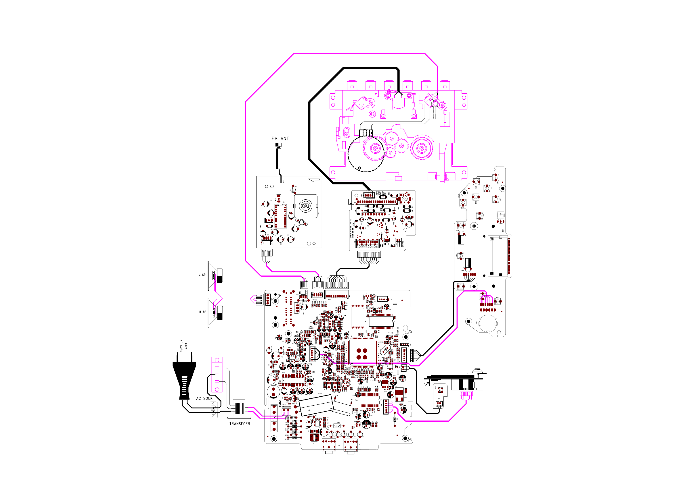
SET WIRING DIAGRAM
2 - 1
2 - 1
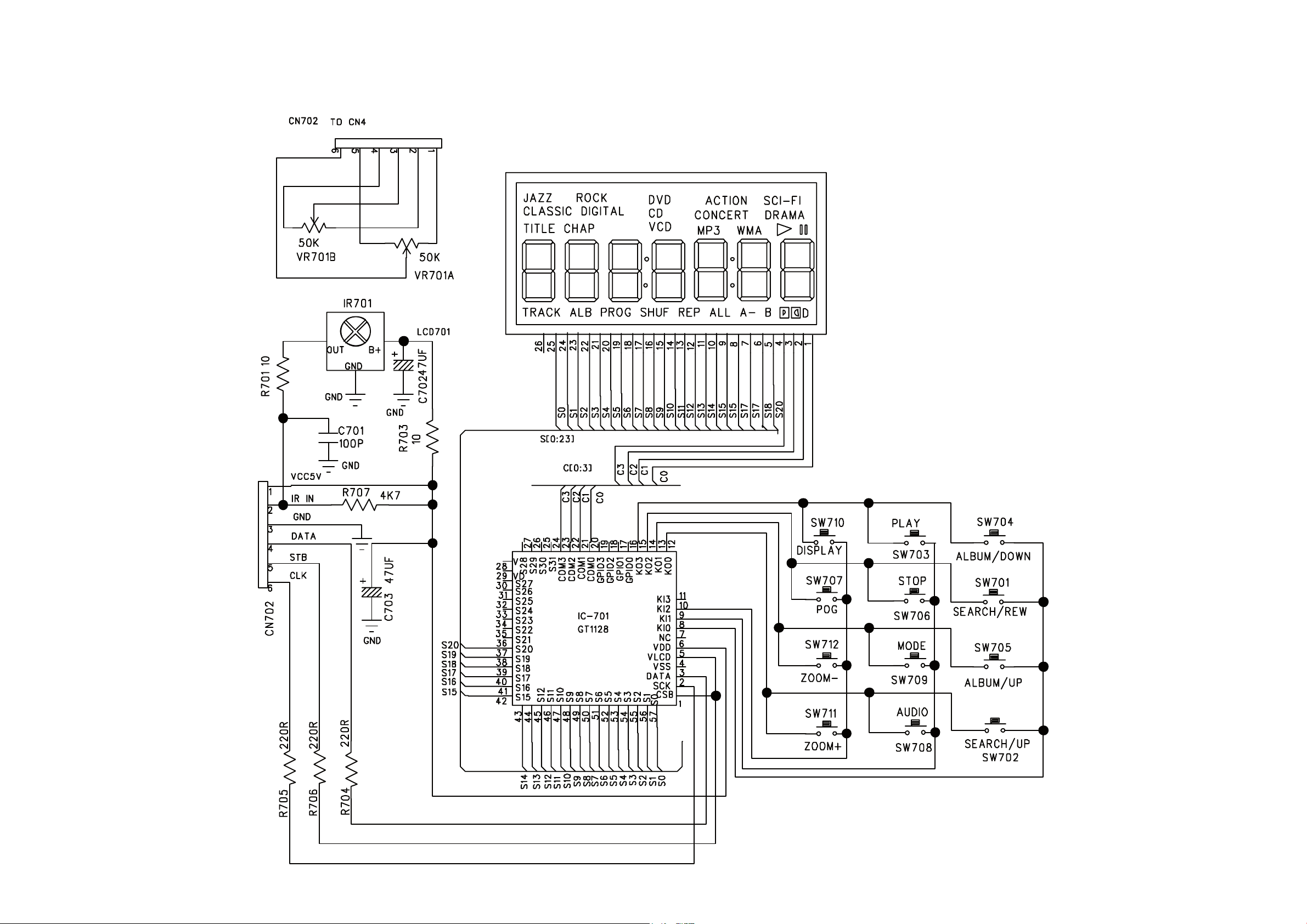
CIRCUIT DIAGRAM - CONTROL BOARD
3 - 13 - 1
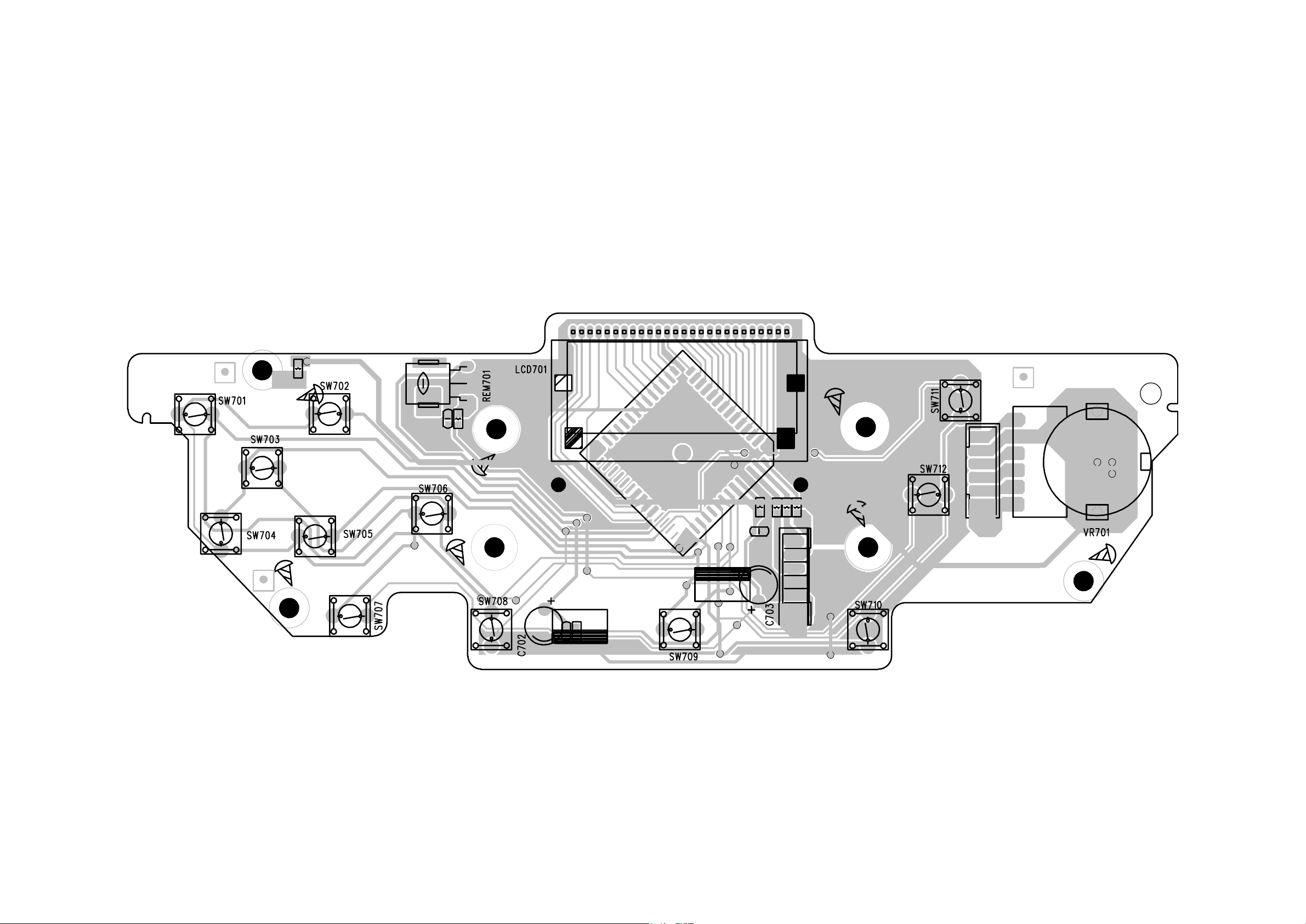
LAYOUT DIAGARM - CONTROL BOARD
3 - 2
3 - 2
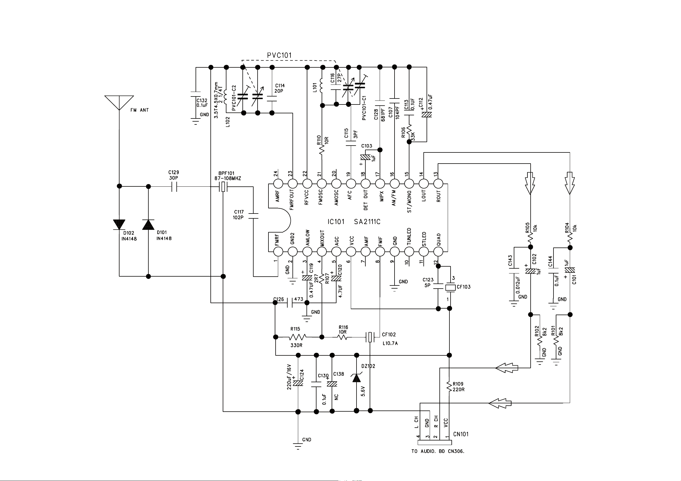
CIRCUIT DIAGRAM - TUNER BOARD
4 - 1 4 - 1
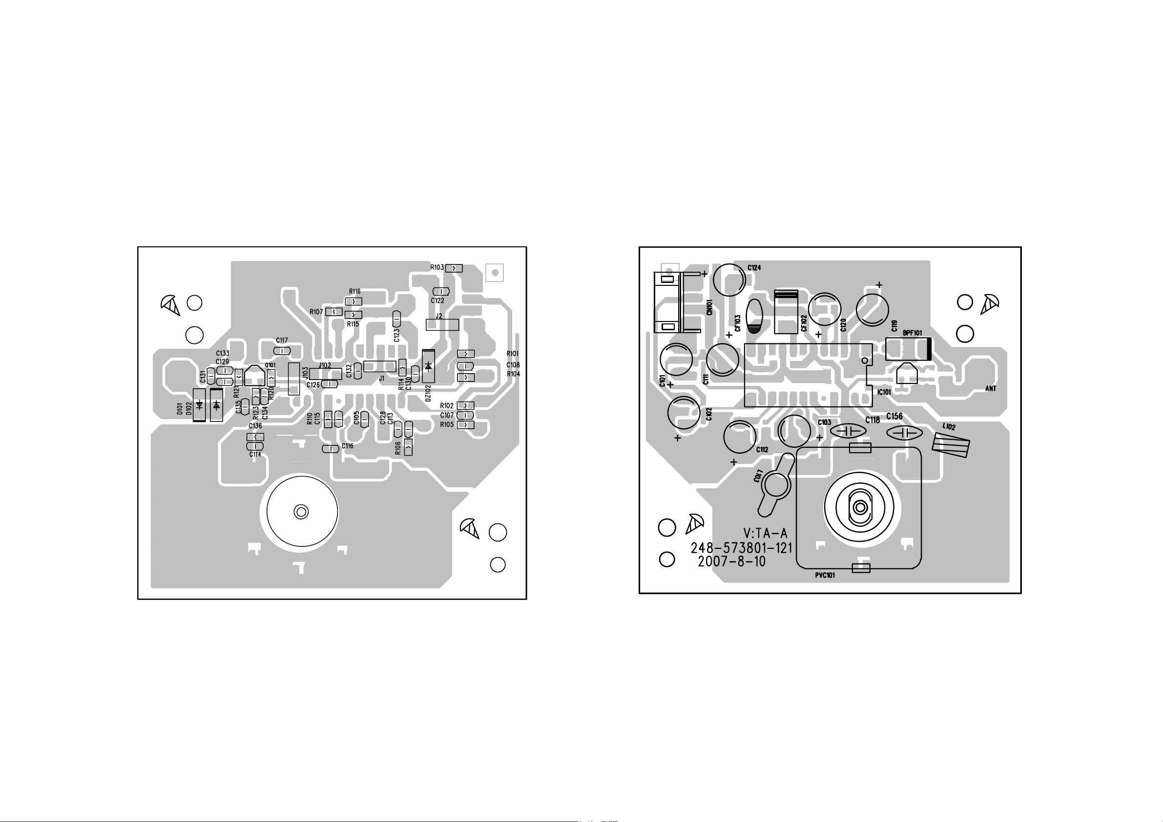
LAYOUT DIAGARM - TUNER BOARD
4 - 2
4 - 2
 Loading...