

Page 1
Obstetrical Care
SERVICE GUIDE
Avalon Fetal Monitor
FM40 / FM50
FETAL MONITORING
Page 2

Printed in Germany
*M2703-9000C*
Part Number M2705-9000A
451261025951
S
Page 3

M2705-9000A
1Table of Contents
1 Introduction 1
Who Should Read This Guide 1
What to Do Next 1
Repair Strategy 2
Manufacturer’s Information 2
Passwords 3
Warnings and Cautions 3
2 Site Preparation 5
Introduction 5
Site Planning 5
Roles and Responsibilities 5
Site Preparation Responsibilities 5
Procedures for Local Staff 6
Procedures for Philips Personnel 7
Site Requirements 7
Space Requirements 7
Environmental Requirements 7
Safety Requirements (Customer or Philips) 8
Electrical Requirements (Customer or Philips) 8
Connecting Non-Medical Devices 8
Cabling Options and Requirements for Connection to OB TraceVue 9
Mounting Options 9
PS/2 Input Devices 10
Displays and Touch Devices 10
M8031B: 15” TFT Medical Grade Touch Display 10
M8033C: 17” TFT Medical Grade Touch Display 10
Video Cables for Remote Displays 11
3 Installation Instructions 13
Initial Inspection 13
Visual Inspection 13
Electrical Inspection 13
Claims for Damage 13
Repackaging for Shipment or Storage 14
Mounting Instructions 14
Line Voltage Selection 14
Rear View 15
Connecting the Monitor to AC Mains 15
i
Page 4

Connecting the Monitor to Non-Medical Devices 15
Connecting a Remote Display via the MIB/RS232 Interface 16
Installing a Remote Display 16
Mounting Remote Displays 16
Before Using the Monitor 16
Checking and Setting Line Frequency 17
Checking/Setting Paper Scale 17
Checking/Setting Paper Speed 18
Configuring the Equipment Label 18
Configuring SmartKeys 18
PS/2 Keyboard/Mouse 18
4 Theory of Operation 19
Monitor Hardware Overview 19
Power Supply 20
Fetal Sensor Connector Block 20
API (All Peripheral Interfaces) Board 20
Main CPU Board 21
Fetal Recorder (Thermal Printer Unit) 21
Thermal Line Printhead (TLPH) 21
Paper Sensor 21
Stepper Motor 21
LCD Display and Touchscreen 21
Noninvasive Blood Pressure Assembly 21
SpO2 Assembly 21
Input/Output Interface Boards 22
Transducer Hardware Overview 22
Tr a n s d u c e r Ty p e s 23
Functional Description of the Transducer CPU 23
CPU (Micro Controller) 23
Analog-to-Digital Converter 23
Communication Transceiver (CAN Bus Driver) 23
EEPROM 23
Toco Transducer Frontend 23
Ultrasound Transducer Frontend 23
Toco+ Transducer Frontends 24
To co Fr o n te n d 24
IUP Frontend 24
ECG Frontend 24
Patient Module Frontends 24
Avalon CTS Interface Cable (TMIF) 24
5 Rear Interfaces 25
LAN / RS232 Interface 25
Dual PS/2 Interface 26
MIB / RS232 Interface 26
ii
Page 5

Telemetry Interface 26
VGA Video Out 26
6 Connection to a Network 27
Network Infrastructure Requirements 27
Connection Indication Messages 27
Broadcast 27
Unicast 28
Equipment Label and OB TraceVue Fetal Monitor Domain Name 28
7 Testing and Maintenance 29
Recommended Frequency 29
When to Perform Test Blocks 30
Preventive Maintenance Procedures 31
Noninvasive Blood Pressure Measurement Calibration 31
Fetal Recorder Maintenance 31
Testing Sequence 31
Visual Inspection 32
Before Each Use 32
After Each Service, Maintenance or Repair Event 32
Safety Tests 32
Warnings, Cautions, and Safety Precautions 32
Safety Test Procedures 33
S(1): Protective Earth Resistance Test 34
S(2): Equipment Leakage Current Test - Normal Condition 34
S(3): Equipment Leakage Current Test - Single Fault Condition 35
S(4): Applied Part Leakage Current - Mains on Applied Part 35
System Test 37
What is a Medical Electrical System? 37
General Requirements for a System 37
System Example 37
Performance Assurance Tests 38
Noninvasive Blood Pressure Performance Tests 38
Accuracy Test 38
Leakage Test 39
Linearity Test 39
Valve Test 40
Expected Test Results 40
SpO2 Performance Test 40
Expected Test Results 40
Measurement Validation 40
Reporting of Test Results 41
Carrying Out and Reporting Tests 42
Other Regular Tests 43
Transducers and Patient Modules: Functional Tests 43
Ultrasound Transducer Electrical Check 43
iii
Page 6

Toco Transducer Electrical Check 44
Testing the Patient Module (M2738A)/Toco+ Transducer (M2735A): DECG Mode 45
Testing the Patient Module (M2738A)/Toco+ Transducer (M2735A): MECG Mode 46
Testing the Patient Module (M2738A)/Toco+ Transducer (M2735A): IUP Mode 47
To uc h s cr e e n C a l i b ra ti o n 48
Disabling/Enabling Touch Operation 49
Checking the Fetal Recorder Offset 49
Setting the Fetal Recorder Offset 49
Fetal Recorder Selftest Report 50
8 Troubleshooting 53
Who Should Perform Repairs 53
Replacement Level Supported 53
Checking Revision Information 53
Trace Header 54
Hardware Revision Check 54
Software Revision Check 55
Obtaining Replacement Parts 55
Troubleshooting Guide 55
Checks for Obvious Problems 55
Checks Before Opening the Instrument 55
Checks with the Instrument Switched On, AC connected 55
Individual Parameter INOPs 56
Initial Instrument Boot Phase 57
Troubleshooting Tables 57
How to Use the Troubleshooting Tables 57
Boot Phase Failures 58
Screen is Blank 58
Touchscreen not Functioning 59
General Monitor INOP Messages 60
Network Status Icons 61
Alarm Tones 61
Alarm Behavior 61
Fetal Recorder 61
LAN / RS232 64
Keyboard/Mouse not Functioning 64
Remote Touch Display not Responding (MIB/RS232) 65
No Video on Remote Display 65
Tr a n s du c e r s 6 6
Status Log 67
Troubleshooting with the Support Tool 68
Troubleshooting the Individual Measurements or Applications 68
9 Parts 71
Monitor 71
Tr a n s d u c e r s 73
iv
Page 7

Patient Modules 74
Interface Cables 74
Assemblies and Kits 75
Front Bezel Assembly 75
Main CPU Board 76
API Board Kit 76
Noninvasive Blood Pressure Assembly 76
Recorder Assembly 77
Thermal Line Printhead (TLPH) 77
Loudspeaker Assembly 77
To p C o ve r 78
AC/DC Power Supply 78
SpO2 Board 78
Interface Boards 79
Fetal Sensor Socket Connector Kit 79
Rear (Telemetry) Connector Kit 79
SpO2 Connector Kit 80
Noninvasive Blood Pressure (NBP) Connector Kit 80
Camlock Kit 80
FM Small Parts Kit - Plastic Parts and Labels 81
FM Small Parts Kit - Screws and Cables 83
Transducer Cable Assembly 84
Belt Button Kit 84
10 Disassembly and Reassembly 85
Introduction 85
How to Use this Chapter 85
Tools Required 86
Screws Used 86
Screw Map 87
Serial Numbers 87
Removing the Top Cover 88
Refitting the Top Cover 89
Removing the Power Supply Assembly 90
Refitting the Power Supply Assembly 91
Removing the Loudspeaker Assembly 91
Refitting the Loudspeaker Assembly 92
Removing the Noninvasive Blood Pressure Assembly 92
Refitting the Noninvasive Blood Pressure Assembly 93
Removing the SpO2 Assembly 94
Refitting the SpO2 Assembly 94
Removing the Interface Boards 95
Refitting the Interface Boards 96
Removing the Main CPU Board 96
Refitting the Main CPU Board 98
Removing the Front Bezel Assembly 99
v
Page 8

Refitting the Front Bezel Assembly 101
Removing the Telemetry Socket Connector Block 102
Refitting the Telemetry Socket Connector Block 102
Removing the Sensor Socket Connector Block 103
Refitting the Sensor Socket Connector Block Assembly 104
Removing the API Board 105
Refitting the API Board 107
Removing the Recorder Assembly 107
Refitting the Recorder Assembly 110
Removing the Thermal Line Printhead (TLPH) 111
Refitting the TLPH 112
Transducer Disassembly/Reassembly 113
Exchanging the Transducer Cable 113
Exchanging the Transducer Belt Button 115
11 Upgrades 117
FM40/50 Upgrade Options 117
Installing Upgrade Options 118
Option C73 118
Options J22 and J70 118
Software and Firmware Upgrades 118
12 Understanding Configuration 119
What is Configuration Mode? 119
Understanding Settings 120
Entering and Leaving Configuration Mode 120
Storing Changes in the User Defaults 121
Loading the Factory Default 122
Loading the User Defaults 122
Loading Configurations Using the Support Tool 123
About Configuration Files (.cfg) 123
Selecting the Correct Configuration 123
13 Configuration Settings Appendix 125
Documenting Monitor Configurations 125
Using the Configuration Tables 125
Configuration Table Example 126
Understanding Configuration Implications 126
Measurement-Related Settings 127
Color Configuration 127
Configuring FHR (Ultrasound) 127
FHR Configuration Implications 127
Configuring Toco 128
Configuring IUP 128
Configuring DFHR (DECG) 128
DFHR Configuration Implications 128
vi
Page 9

Configuring MHR (ECG)/Pulse 129
ECG/Pulse Configuration Implications 129
Configuring SpO
Configuration Implications 130
SpO
2
2
130
Configuring Noninvasive Blood Pressure (NBP) 132
NBP Configuration Implications 132
Monitor-Related Settings 133
Configuring Alarms 133
Alarm Settings Configuration Implications 133
Configuring the NST Timer 134
NST Timer Configuration Implications 134
Configuring Fetal Recorder Settings 135
Recorder Configuration Implications 135
Configuring User Interface Settings 136
User Interface Configuration Implications 136
Configuring Global SmartKeys 138
Global SmartKeys Configuration Implications 138
Changing the Selection and Sequence of Global SmartKeys 138
Hardware Settings 139
Global Settings 139
Global Settings Configuration Implications 139
vii
Page 10

viii
Page 11

1
1Introduction
This Service Guide contains technical details for the Avalon FM40 and FM50 Fetal/Maternal
Monitors. It provides a technical foundation to support effective troubleshooting and repair. It is not a
comprehensive, in-depth explanation of the product architecture or technical implementation. It offers
enough information on the functions and operations of the monitoring systems so that engineers who
repair them are better able to understand how they work. It covers the physiological measurements and
the monitor hardware that acquires and displays them.
The Avalon FM40/FM50 Fetal Monitor Service Guide supplements the maintenance and
troubleshooting procedures, carried out by the operator, that are described in the Instructions for Use.
Refer to the Instructions for Use for maintenance and troubleshooting procedures that may be
performed during normal operation.
Only qualified service personnel should attempt to install the system, disassemble the monitor, remove
or replace any internal assemblies, or replace the transducer cable or belt buttons.
Who Should Read This Guide
This guide is for biomedical engineers or technicians responsible for troubleshooting, repairing, and
maintaining Philips’ Avalon fetal monitors.
You must:
•understand English
• be familiar with standard medical equipment installation procedures
• be familiar with current conventional technical terms as used throughout this guide
What to Do Next
Familiarize yourself with the contents of this guide and the Instructions for Use before attempting to
service or repair the system.
1
Page 12

1 Introduction Repair Strategy
Repair Strategy
The Service Support Tool software helps you to determine whether a fault is a hardware or software
problem. The main replaceable parts are:
• unit exchange for the transducers
•replacement of
–the top cover
– the power supply assembly
– the loudspeaker assembly
– the noninvasive blood pressure assembly
–the SpO
– the interface boards (RS232/LAN, dual PS/2 and MIB/RS232)
–the main CPU board
– the front bezel assembly
– the telemetry socket connector block
– the sensor socket connector block
–the API board
– the recorder assembly
– the thermal line printhead (TLPH)
–the transducer cable
– the transducer belt button
See Chapter 9, “Parts” for part numbers, and Chapter 10, “Disassembly and Reassembly” for repair
details.
assembly
2
Repair or replacement of individual components on the boards is not supported, and should never be
attempted.
For tests that you are required to perform after repairs, refer to “When to Perform Test Blocks” on
page 30.
Manufacturer’s Information
© Copyright 2003 - 2008. Koninklijke Philips Electronics N.V.
All Rights Reserved.
Philips Medizin Systeme Böblingen GmbH
Hewlett-Packard-Str. 2
71034 Böblingen, Germany
2
Page 13

Passwords 1 Introduction
Passwords
In order to access different modes within the monitor a password may be required. The passwords are
listed below.
Monitoring Mode: No password required
Configuration Mode: 71034
Demo Mode: 14432
Service Mode: 1345
Refer to Chapter 12, “Understanding Configuration” before making any changes to the monitor
configuration.
Warnings and Cautions
In this guide:
•A warning alerts you to a potential serious outcome, adverse event or safety hazard. Failure to
observe a warning may result in death or serious injury to the user or patient.
•A caution alerts you where special care is necessary for the safe and effective use of the product.
Failure to observe a caution may result in minor or moderate personal injury or damage to the
product or other property, and possibly in a remote risk of more serious injury.
3
Page 14

1 Introduction Warnings and Cautions
4
Page 15

Introduction
This section describes the procedures you should follow to plan and prepare a site for an Avalon
FM40/FM50 fetal monitor installation.
• Site planning.
• Roles and responsibilities for local and Philips personnel.
Site Planning
The careful planning of the site for the FM40/FM50 monitor is essential for its safe and efficient
operation. A consulting schedule should be established between the Customer and Philips Sales and
Support Representatives, to ensure that all preparations are completed when the system is delivered.
2
2Site Preparation
The site planning phases prior to equipment installation are:
Location: Planning the location of the various system components.
Environment: Confirming and correcting, as necessary, the environment of the proposed installation
site(s).
System Capabilities: Explaining the possibilities for system expansion.
Mounting: Referencing the mounting hardware information website for the listing of suitable
mounting hardware recommended for use with the various system components, and all details on the
available mounts and accessories.
Cabling: Identifying the requirements for the cabling, conduiting and faceplates for connecting the
various system components.
Roles and Responsibilities
This section describes the procedures necessary to prepare a site for a system installation. The
procedures are grouped into two parts: procedures that local staff or contractors are responsible for, and
procedures that Philips personnel are responsible for.
Site Preparation Responsibilities
Local Staff
• Ensure that all safety, environmental and power requirements are met.
• Provide power outlets.
• Prepare mounts, and consult Philips for detailed mounting requirements.
5
Page 16

2 Site Preparation Introduction
• Pull cables, install conduit, install wallboxes.
Philips Personnel
• Provide the customer with the safety, environmental and power requirements.
•Assemble mounts, as necessary.
• Provide requirements for cabling.
Procedures for Local Staff
The following tasks must be completed before the procedures for Philips personnel may be started.
• Providing Power Outlets
Provide a power outlet in the vicinity (1 m or 3 ft) or any peripheral equipment.
WARNING Only the power cables provided with the system may be used. For reasons of safety, power (mains)
extension cables or adapters shall not be used.
• Preparing Mounts
Where ceiling, wall, or shelf mounts are required for mounting the equipment, the customer is
responsible for the following:
– Providing and installing all hardware which is required to install the mounting hardware supplied
by Philips as detailed in the installation notes.
– Making sure that all ceilings, walls, and mounting rails that supports mounting hardware are
suitable for their proposed load.
WARNING It is the customer's responsibility to have the attachment of the mounting hardware to the ceiling, wall,
or mounting rail and the construction of the ceiling, wall, or mounting rail evaluated for structural
integrity and compliance with all local, state and any other required codes by a registered, professional,
structural and/or mechanical engineer.
Although considerable effort has been made to ensure the safety of the ceiling mount installation and
or mounting guidelines, it is to be understood that the installation itself is beyond the control of Philips
Medical Systems. Accordingly, Philips Medical Systems will not be responsible for the failure of any
such installation.
• Providing Conduit
– Providing conduit and/or trunking of a sufficient cross-sectional area for the planned cables and
possible future expansion (for additional components or systems).
– Providing and/or installing suitable wall boxes to accommodate the faceplates.
•Pulling Cables
WARNING NEVER run power cables through the same conduit or trunking used for system cables.
•Installing Wall Boxes
6
Page 17

Site Requirements 2 Site Preparation
It is the customer's responsibility to provide and install wallboxes to house faceplates. The customer
must notify the Philips installation coordinator of which size is to be used.
Procedures for Philips Personnel
Before you begin the procedures in the installation sections, ensure that the customer has completed all
necessary preparations outlined in the previous section, “Procedures for Local Staff.”
Site Requirements
The site requirements are listed in this section.
Space Requirements
The situating of the monitor should be planned such that the nursing staff are able to monitor the
patient with relative ease, with all patient connectors and controls readily available and the displays
clearly visible. The location should also allow access to service personnel without excessive disruption
and should have sufficient clearance all round to allow air circulation.
Dimensions and weight:
Monitor:
Size (W x H x D): 420 x 172 x 370 mm (16.5 x 6.8 x 14.6 in)
Weight; < 9.0 kg (19.8 lb)
Transducer:
Size (diameter): 83 mm (3.27 in)
Weight (without cable): 190g (6.7 oz.)
Environmental Requirements
The environment where the FM40/FM50 monitor will be used should be reasonably free from
vibration, dust and corrosive or explosive gases. The ambient operating and storage conditions for the
FM40/FM50 monitor must be observed. If these conditions are not met, the accuracy of the system
will be affected and damage can occur.
.
Monitor (M2704A/M2705A)
Interface Cable for Avalon CTS (M2731-60001/M2732-60001)
Temperature Range Operating 0°C to 45°C (32°F to 113°F)
Storage
Humidity Range Operating <95% relative humidity @ 40°C/104°F
Storage
Altitude Range Operating -500 to 3000 m/-1640 to 9840 ft.
Storage
-20°C to 60°C (-4°F to 140°F)
<90% relative humidity @ 60°C/140°F
-500 to 13100 m/-1640 to 43000 ft.
Transducers (M2734A/M2735A/M2736A/M2738A)
Temperature Range Operating 0°C to 40°C (32°F to 104°F)
Storage
-20°C to 60°C (-4°F to 140°F)
7
Page 18

2 Site Preparation Site Requirements
Transducers (M2734A/M2735A/M2736A/M2738A)
Humidity Range Operating <95% relative humidity @ 40°C/104°F
Storage
Altitude Range Operating -500 to 3000 m/-1640 to 9840 ft.
Storage
SpO2 Sensors
Operating Temperature Range 0°C to 37°C (32°F to 98.6°F)
<90% relative humidity @ 60°C/140°F
-500 to 13100 m/-1640 to 43000 ft.
Safety Requirements (Customer or Philips)
The monitor is an electrical Class I device in which protection against electric shock does not rely on
basic insulation only, but which includes an additional safety precaution, in that means are provided
for the connection of the equipment to a protective earth conductor in the fixed wiring installation in
such a way that accessible metal parts cannot become live in the event of a failure of the basic
insulation.
WARNING • Always use the supplied power cord with the earthed mains plug to connect the monitor to an
earthed AC mains socket. Never adapt the mains plug from the power supply to fit an unearthed AC
mains socket.
• Do not use additional AC mains extension cords or multiple portable socket-outlets. If a multiple
portable socket-outlet without an approved separating transformer is used, the interruption of its
protective earthing may result in equipment leakage currents equal to the sum of the individual
earth leakage currents, so exceeding allowable limits.
Electrical Requirements (Customer or Philips)
Line Voltage Connection
The FM40/FM50 monitor uses < 60 W.
Line Voltage: the FM20/FM30 monitor may be operated on ac line voltage ranges of
100 to 240V (50/60 Hz).
Connecting Non-Medical Devices
The standard IEC/EN 60601-1-1 applies to any combination of devices, where at least one is a medical
device. Therefore IEC/EN 60601-1-1 must still be met after all devices are connected.
WARNING • Do not use a device in the patient vicinity if it does not comply with IEC/EN 60601-1. The whole
installation, including devices outside of the patient vicinity, must comply with IEC/EN 60601-1-1.
Any non-medical device, including a PC running an OB TraceVue system, placed and operated in
the patient’s vicinity must be powered via a separating transformer (compliant with IEC/EN 606011-1) that ensures mechanical fixing of the power cords and covering of any unused power outlets.
• Do not connect any devices that are not supported as part of a system.
8
Page 19
Site Requirements 2 Site Preparation
Whenever you combine equipment to form a system, for example, connecting the monitor to an OB
TraceVue system, perform a system test according to IEC/EN 60601-1-1 (see “System Test” on
page 38).
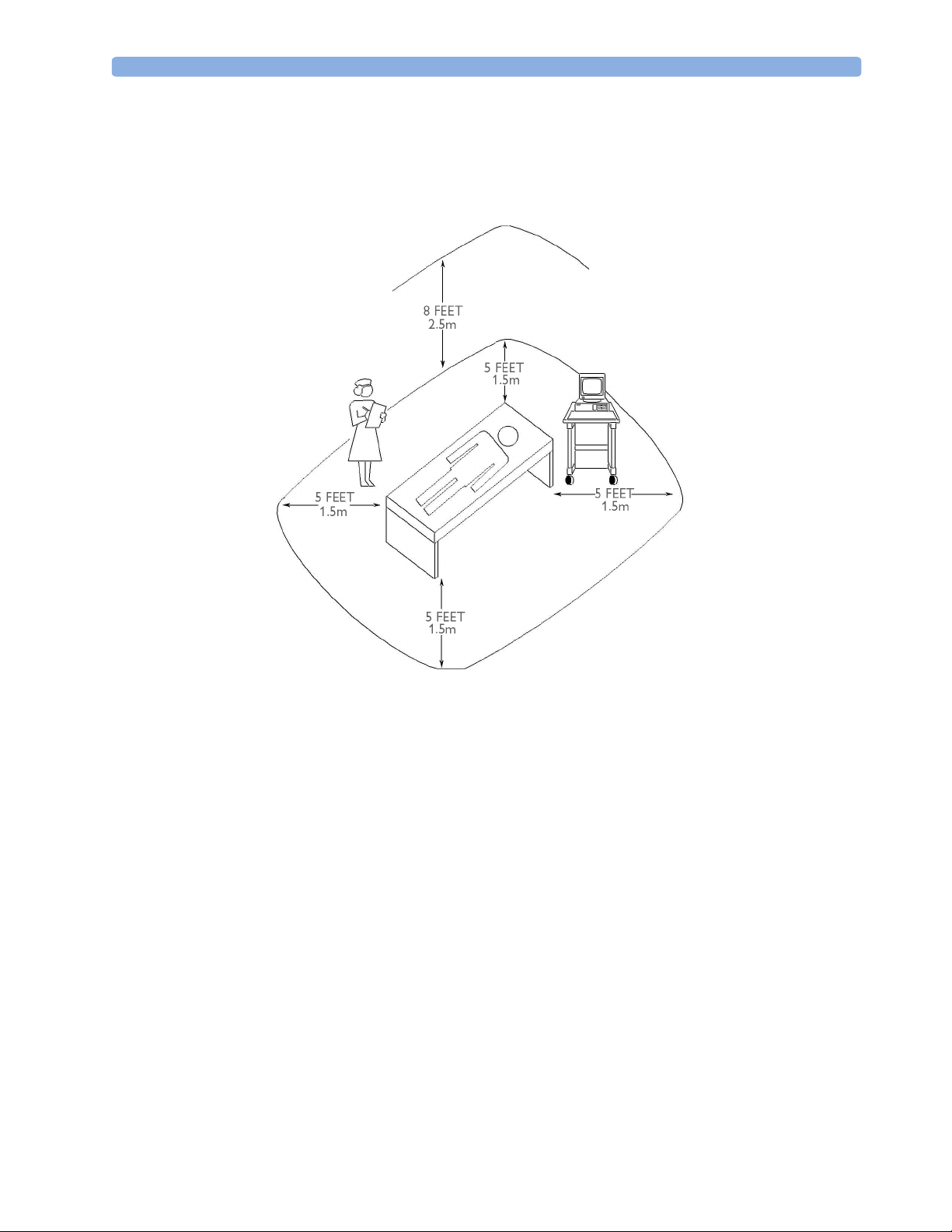
Figure 1 Equipment Location in the Patient Vicinity
Cabling Options and Requirements for Connection to OB TraceVue
For cabling options and requirements for connection to an OB TraceVue system, refer to the OB
TraceVue Site Preparation Guide and the OB TraceVue Service Guide.
Mounting Options
See “Mounting Hardware” on page 61 for a list of mounting options. Refer to “Mounting
Instructions” on page 12, or contact your local Philips representative for advice on mounting the
monitor.
9
Page 20

2 Site Preparation Site Requirements
PS/2 Input Devices
The following table describes the input devices which can be connected to the monitor via the optional
PS/2 interface.
Product Option
Number
M8024A #A01 862454 989803124741 Slimline Keyboard with integrated Trackball
M8024A #B01 M4046-60104 451261000661 Optical Mouse USB / PS/2
M8024A #C01 M4046-60103 451261000651 Wired Track Ball USB / PS2
M8024A #C02 M4046-60105 451261000671 Wireless Track Ball
M8024A #C03 M4046-60106 451261000681 Wired off table Track Mouse
Part Number 12NC Part
Number
Description
Displays and Touch Devices
The following two tables describe the remote displays that can be connected to the monitor’s video
output connector.
For touch operation, the MIB/RS232 interface is required. See “Connecting a Remote Display via the
MIB/RS232 Interface” on page 16.
M8031B: 15” TFT Medical Grade Touch Display
Product Number Part Number 12NC Part
Number
M8031B M8031-60001 45121001911 15” Medical Grade Display with Touch
- M8031-68001 451261001941 Exchange 15” Medical Grade Display with Touch
- M8031-60005 451261001921 Power Supply 12V for M8031B Display
- M8031-64001 451261001931 Power Supply Mounting for M8031B Display
- M8031-04701 451261001901 Monitor Desk Stand for M8031B/M8033C
- 2090-0860 453563463201 Backlights for M8031B
Description
M8033C: 17” TFT Medical Grade Touch Display
Product Number Part Number 12NC Part
Number
M8033C M8033-60071 451261009151 17” Medical Grade Display with Touch
- M8033-68071 451261009161 Exchange 17” Medical Grade Display with Touch
- M8031-04701 451261001901 Monitor Desk Stand for M8031B/M8033C
- M8033-64603 451920880311 Backlights for M8033C
10
Description
Page 21

Site Requirements 2 Site Preparation
Video Cables for Remote Displays
Product Option
Number
M8022 #VA2 M3080-61606 453563484451 1.5 m Analogue Video Cable Kit
M8022 #VA3 M3080-61602 453563334661 3 m Analogue Video Cable Kit
M8022 #VA6 M3080-61603 453563334671 10 m Analogue Video Cable Kit*
Both ends are terminated with HDSUB15 (“VGA”) straight connectors.
*Built on demand
Part Number 12NC Part
Number
Description
11
Page 22

2 Site Preparation Site Requirements
12
Page 23

3Installation Instructions
The information contained in this chapter, in addition to that given in the Instructions for Use, should
enable the monitor to be installed ready for use (the preparation and planning should be adhered to as
specified in the “Site Preparation” chapter). Safety checks and inspection procedures for mounts are
explained in the “Testing and Maintenance” chapter, and configuration of the system is explained in
the “Configuration” chapter.
Please keep the packing materials until you have completed the initial inspection, in case there is a
defect on arrival.
Initial Inspection
Inspect the delivery on arrival.
3
Visual Inspection
Open the shipping container(s) and examine each part of the instrument for visible damage, such as
broken connectors or controls, or scratches on the equipment surfaces. If the shipping carton/container
is undamaged, check the cushioning material and note any signs of severe stress as an indication of
rough handling in transit. This may be necessary to support claims for hidden damage that may only
become apparent during subsequent testing.
Electrical Inspection
The instrument has undergone extensive testing prior to shipment. Safety testing at installation is not
required (except in situations where devices are interconnected forming a system, see “Connecting
Non-Medical Devices” on page 8). An extensive self check may be performed. This recommendation
does not supersede local requirements.
All tests are described in the “Testing and Maintenance” chapter of this manual.
Claims for Damage
When the equipment is received, if physical damage is evident or if the monitor does not meet the
specified operational requirements of the patient safety checks or the extended self check, notify the
carrier and the nearest Philips Sales/Support Office at once. Philips will arrange for immediate repair or
replacement of the instrument without waiting for the claim settlement by the carrier.
13
Page 24

3 Installation Instructions Repackaging for Shipment or Storage
Repackaging for Shipment or Storage
If the instrument is to be shipped to a Philips Sales/Support Office, securely attach a label showing the
name and address of the owner, the instrument model and serial numbers, and the repair required (or
symptoms of the fault). If available and reusable, the original Philips packaging should be used to
provide adequate protection during transit. If the original Philips packaging is not available or reusable
please contact the Philips Sales/Support Office who will provide information about adequate
packaging materials and methods.
Mounting Instructions
Every type of compatible mounting solution is delivered with a complete set of mounting hardware
and instructions. Refer to the Site prep chapter for a list of mounting options. Refer to the
documentation delivered with the mounting hardware for instructions on assembling mounts.
WARNING It is the customer's responsibility to have the attachment of the mounting hardware to the ceiling, wall,
or mounting rail and the construction of the ceiling, wall, or mounting rail evaluated for structural
integrity and compliance with all local, state and any other required codes by a registered, professional,
structural and/or mechanical engineer.
Ensure that this commitment has been met before assembling mounts.
Line Voltage Selection
You do not need to set the line voltage, as this is done automatically by the power supply. The monitor
has a wide-range power supply that allows you to operate the monitor from an AC (alternating current)
power source of 100 V to 240 V (± 10%) and 50/60 Hz (± 5%).
14
Page 25
Rear View 3 Installation Instructions
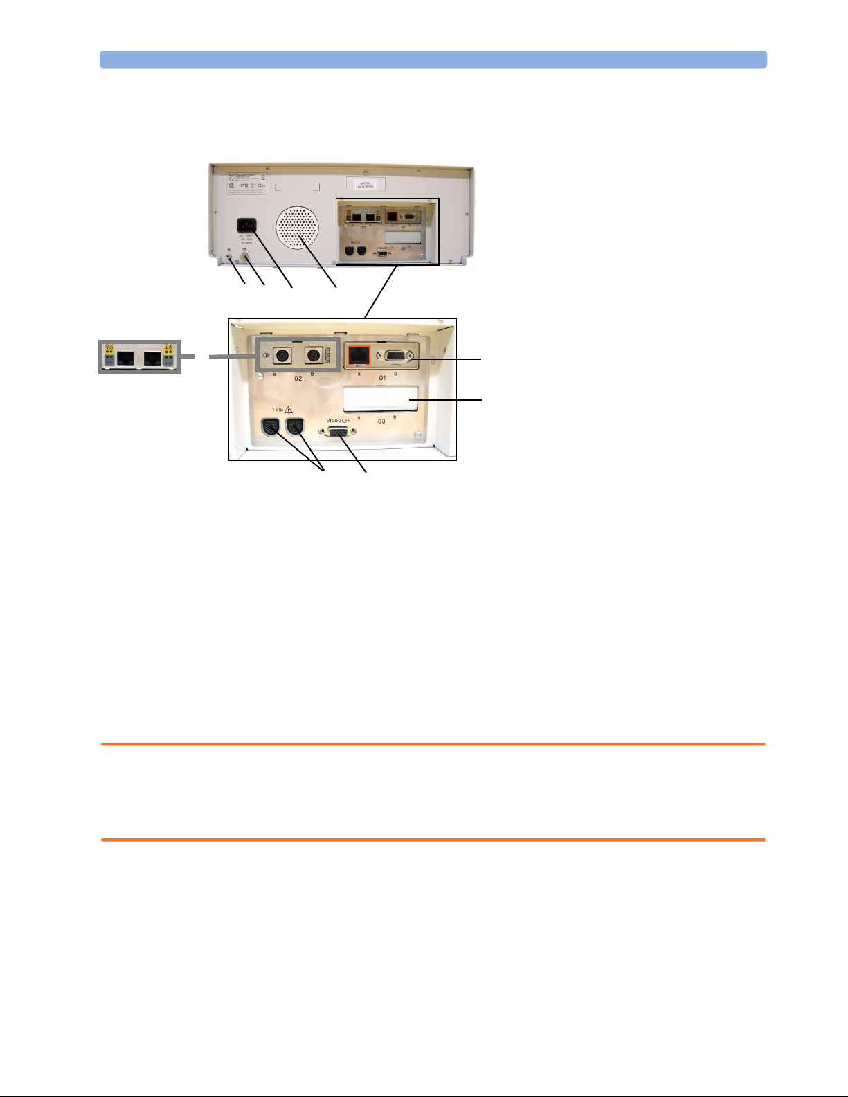
Rear View
1 Reserved for future use: protective
earth intended for use in system
installations.
2 Equipotential grounding point
3 Power cord connector
4 Loudspeaker
5 Slot 01 for optional LAN / RS232
12
3
4
(A)(B)
6
9
8
5
7
system interface (for connection to an
obstetrical information and
surveillance system)
6 Slot 02 for optional interfaces:
• Either dual PS/2 system interface
(A) for mouse and keyboard
connection)
• Or MIB interface (B) for external
touch screen connection
7 Slot 03 reserved for future use
8 Video output (VGA)
9 Telemetry interface. If not using one of
the fetal sensor sockets, one Avalon
CTS can be connected at a time to
either socket using the M2732-60001
interface cable (with black connector).
Connecting the Monitor to AC Mains
The monitor is an electrical Class I device in which protection against electric shock does not rely on
basic insulation only, but which includes an additional safety precaution, in that means are provided
for the connection of the equipment to a protective earth conductor in the fixed wiring installation in
such a way that accessible metal parts cannot become live in the event of a failure of the basic
insulation.
WARNING • Always use the supplied power cord with the earthed mains plug to connect the monitor to an
earthed AC mains socket. Never adapt the mains plug from the power supply to fit an unearthed AC
mains socket.
• Do not use AC mains extension cords or multiple portable socket-outlets.
Connecting the Monitor to Non-Medical Devices
Connect the monitor to an obstetrical surveillance system, such as OB TraceVue, via the optional
system interface. For cabling requirements, refer to “Cabling Options and Requirements for
Connection to OB TraceVue” on page 9. For safety-related information, refer to “Connecting NonMedical Devices” on page 8, and “System Test” on page 38.
15
Page 26

3 Installation Instructions Connecting a Remote Display via the MIB/RS232 Interface
Connecting a Remote Display via the MIB/RS232 Interface
The configuration of a specific MIB/RS232 port can be viewed in Configuration Mode and altered in
Service Mode. This is required when a remote display with touchscreen is installed. To configure an
MIB/RS232 port to support a slave display with touchscreen:
1 Select Main Setup.
2 Select Hardware.
3 Select Interfaces.
4 Select MIB/RS232.
5 Select Touch 1.
NOTE Be aware that if you configure a port, this assignment is retained after a boot up. If the MIB/RS232
board is removed and replaced with a different type of board the settings are deleted. If the MIB/
RS232 board is then refitted, you must reconfigure the MIB/RS232 port. The configuration of MIB/
RS232 is not cloned between monitors.
After loading the Factory Defaults, you will need to reconfigure the MIB/RS232 port to re-enable
the touch operation of the connected remote display.
Installing a Remote Display
The monitor is tested and approved for use with the following remote displays:
• Philips M8031B 15” Remote Display
• Philips M8033C 17” Remote Display
The monitor has an analog-only video output signal, with VGA resolution. Use a standard VGA video
cable to connect the remote display to the video output on the rear of the monitor.
Mounting Remote Displays
Mounting solutions for the M8031B and M8033C remote displays must be purchased separately.
Please refer to the installation instructions which ship with the mounting solution purchased.
Before Using the Monitor
WARNING Before starting monitoring, check that the configuration meets your requirements.
Check that the following configuration settings are suitable:
•Line Frequency
• Paper Scale
16
•Paper Speed
•Equipment Label
•Configured SmartKeys
Page 27

Before Using the Monitor 3 Installation Instructions
• Input device configuration (if using an external keyboard or mouse)
• Remote display settings (if using a remote display, see “Connecting a Remote Display via the MIB/
RS232 Interface” on page 16).
If you need to enter configuration mode to change settings:
1 In the Main Setup menu, select Operating Modes.
2 Select Config and enter the passcode.
The passcode for configuration mode is given in the monitor’s service documentation.
The monitor displays Config at the right hand side of the status line and in the center of the Screen
while you are in configuration mode.
Before you leave configuration mode, always be sure to store any changes you made. You must store
changes made to each Settings Block and to each Profile, individually. As it may be difficult to
remember whether the settings you changed belong to a Monitor Settings block or a Measurement
Settings block, we recommend that you store each block before you leave configuration mode.
To leave configuration mode:
1 Enter the Main Setup menu.
2 Select Operating Modes.
3 Select Monitoring.
Checking and Setting Line Frequency
Before using the monitor, check that the line frequency setting is correct for your location, and change
the setting if necessary in Service Mode.
WARNING An incorrect line frequency setting can affect the ECG filter, and disturb the ECG measurement.
Ensure the line frequency setting is correct.
To set the line frequency:
1 Enter the Main Setup menu.
2 Select Global Settings.
3 Select Line Frequency and select 50Hz or 60Hz from the pop-up list.
Checking/Setting Paper Scale
Check the paper Scale Type (US for paper with a scale of 30-240, or Internat’l for paper with a
scale of 50-210) in the Fetal Recorder menu. In Monitoring Mode, you can see this setting (grayed
out), but you cannot change it. It can be changed in Configuration Mode.
1 Enter the Main Setup menu by selecting the SmartKey .
2 Select Fetal Recorder.
3 Check the current setting for Scale Type. If it is not appropriate, change it in the Fetal Recorder
menu in Configuration Mode:
Select Scale Type to toggle between US and Internat’l.
17
Page 28

3 Installation Instructions Before Using the Monitor
Checking/Setting Paper Speed
Check the paper speed before using the monitor. You can choose a paper speed of 1, 2, or 3
centimeters per minute (cm/min). The default setting is 3 cm/min. In Monitoring Mode, you can see
this setting (grayed out), but you cannot change it. It can be changed in Configuration Mode.
As a change in paper speed results in a change in the appearance of a FHR trace, you are advised to
ensure ALL monitors in your institution are set to the same speed.
To set the paper speed:
1 Enter the Main Setup menu using the SmartKey .
2 Select Fetal Recorder.
3 In the Recorder menu, you can see the current speed setting. Select Recorder Speed.
4 Select the desired speed from the given choices: 1, 2 or 3 cm/min.
Configuring the Equipment Label
OB TraceVue requires a unique equipment label. In OB TraceVue, is possible to prevent connection
to monitors with specific equipment labels by means of a filtering mechanism. For more details, see the
OB TraceVue Instructions for Use.
1 Select the Bed Label screen element to call up the Bed Info menu.
2 Select Equipment Label to call up the onscreen keyboard.
3 Enter the system identifier.
Configuring SmartKeys
Check that the configured SmartKeys are suitable. Configure the SmartKeys preferred by the
institution from a global list Global Smart Keys. The global list of SmartKeys is stored as a unique
monitor setting in the monitor configuration. See the section “Configuring Global SmartKeys” on
page 138 for details on how to configure the global SmartKey list.
PS/2 Keyboard/Mouse
Switch off the monitor before connecting any PS/2 compatible device.
Connect the PS/2 connector to the PS/2 Interface board in the monitor at the slot indicated by the
appropriate symbol.
The default keyboard language setting for all initial configurations is “US”.
To configure the keyboard language manually, go to Service Mode, select Main Setup ->
Hardware -> Keyboard and then select the proper language. Please note that this setting does not
clone.
18
Page 29
4Theory of Operation
This chapter describes the functional operation of the monitor and the transducers. It incorporates features of
the mechanical design, indicating the physical relationship of the assemblies and components.
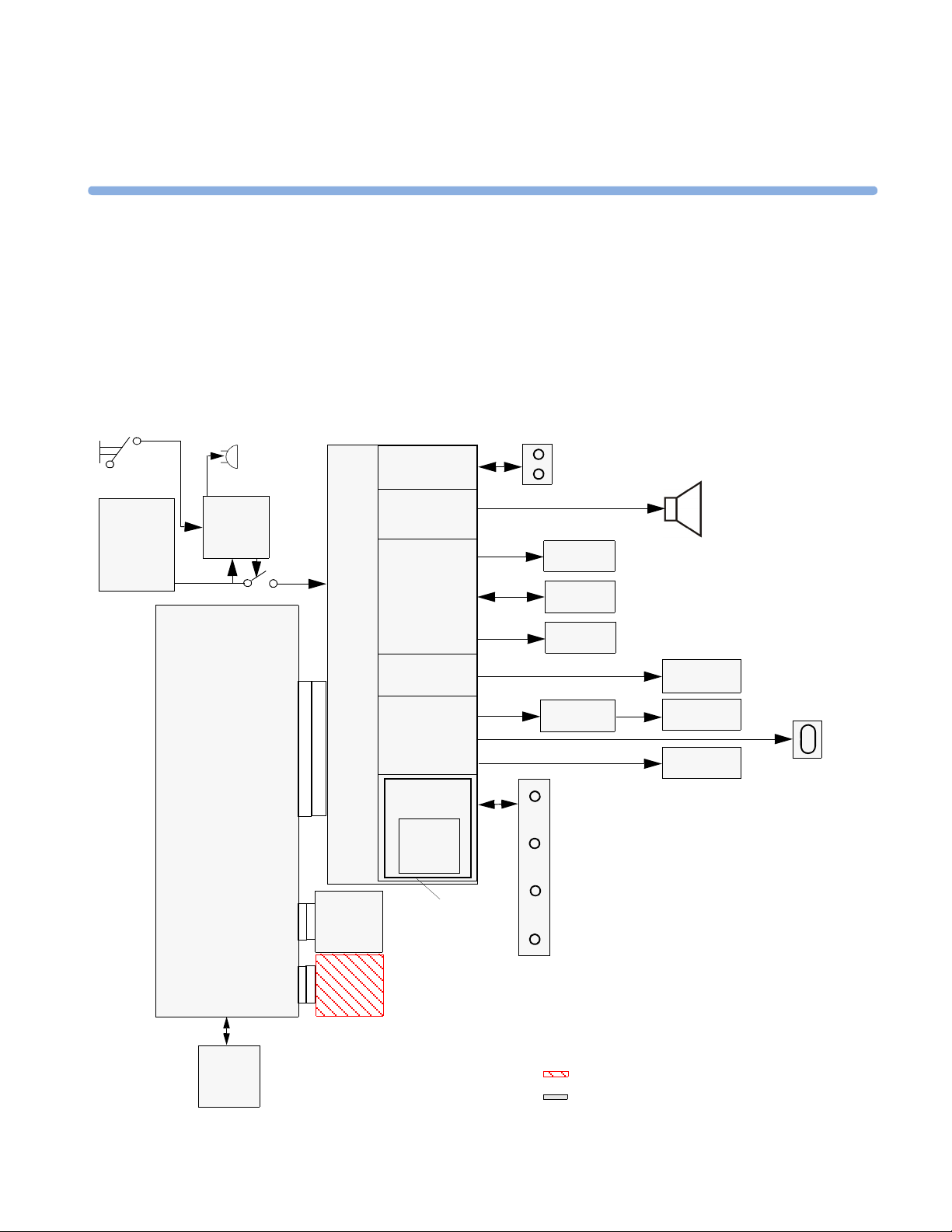
Monitor Hardware Overview
Standby
Button
AC-DC
Power
Interrupt
Bleeper
Stand-by
Control
Telemetry
Interface
Audio
Amplifier
4
Telemetry
Connector Block
Loudspeaker
Printhead
Main CPU Board
API
(All Peripheral Interfaces Board)
IF Board 1
(LAN/
RS232)
IF Board 2
Printer
Control
Touch
Control
Display
Control
Bus
Master
SpO
Floating
Isolation
Paper
Sensor
Stepper
Motor
Touch
Screen
Display
Adapter
2
Fetal Sensor Connector Block
Display
Panel
Backlight
Converter
VGA
Connector
NBP
optional boards
standard boards
19
Page 30

4 Theory of Operation Power Supply
The monitor consists of the following main functional components:
•Power supply
• API (All Peripheral Interfaces) Board
• Main CPU Board
• Fetal Recorder (Thermal Printer Unit)
• Fetal Sensor Connector Block
• Noninvasive Blood Pressure Board
•SpO
• Input /Output Interface Boards:
Board
2
–LAN / RS232
–Dual PS/2 (optional)
– MIB / RS232 (optional)
Power Supply
The power supply is a wide-range input switching unit, with an output of 24V. It is located in the chassis
assembly.
Fetal Sensor Connector Block
Any compatible fetal transducer can be connected in any order to the monitor via the sockets on the
Connector Block. The Connector Block is located on the Bus Master section of the All Peripheral
Interfaces (API) Board, and is exchangeable.
API (All Peripheral Interfaces) Board
The All Peripheral Interfaces (API) Board is connected to the Main CPU Board by a 154-pin 0.5 mm
pitch press fit connector.
20
The recorder is controlled by the Printer Control section of the API Board, which is connected to the
Stepper Motor and the Thermal Printer Unit.
The signals from the transducers or sensors are conveyed from the sensor sockets to the Bus Master section
of the API Board. The Telemetry Interface is also integrated into the API Board.
The Bus Master section is responsible for transducer detection, communicates with the connected
transducers via a CAN bus, and communicates parameter data to the Main CPU Board via a serial link for
further processing and display. It has floating power isolation.
The API Board also controls the display panel and the backlight converter, and also controls the
touchscreen. The display panel is connected to the API Board. The VGA connector is also connected to
the API Board.
The API Board incorporates an audio amplifier which controls the loudspeaker.
Page 31

Main CPU Board 4 Theory of Operation
Main CPU Board
The Main CPU Board controls the monitor’s human interface, and is responsible for the final processing of
data from the Bus Master Board. It sends this data to the TFT display, and to the thermal printer unit for
recording traces and other patient data. It also controls the LAN/RS232 interface board, and the optional
PS/2 and MIB interface boards.
Fetal Recorder (Thermal Printer Unit)
The fetal recorder is located in the front of the chassis assembly. The recorder consists of the following
major parts:
•Thermal Line Printhead (TLPH)
•Paper Sensor
•Stepper Motor
Thermal Line Printhead (TLPH)
The TLPH is located on its own holder in the recorder chassis.
Paper Sensor
The paper sensor hardware consists of a reflective light sensor that detects the black marks on the trace
paper, and paper-out. It is attached to the RFI Bracket, and connected to the Recorder Adapter Board via a
removable cable connector.
Stepper Motor
The stepper motor is a bipolar motor controlled by a micro-stepping motor driver on the Recorder Adapter
Board. The motor is located on the recorder chassis and is connected to the Recorder Adapter Board via a
removable cable connector.
LCD Display and Touchscreen
The LCD Display Assembly consists of a five-wire resistive touchscreen, a 6.5” TFT panel, and a backlight
inverter, all connected to the API Board and fitted into the front bezel assembly.
Noninvasive Blood Pressure Assembly
The optional Noninvasive Blood Pressure Assembly is located in the rear lefthand corner of the chassis
assembly. It is connected via a serial link to the Main CPU Board.
SpO2 Assembly
The optional SpO2 Assembly is physically located on the Bus Master section, but sends data directly to the
Main CPU Board via a serial link.
21
Page 32

4 Theory of Operation Input/Output Interface Boards
Input/Output Interface Boards
There are three interface boards available:
• LAN/RS232 Interface Board, used for connecting to a PC running the Support Tool and to a
surveillance and documentation system such OB TraceVue.
• PS/2 Interface Board (optional), used for connecting an external keyboard or mouse.
• MIB Interface Board (optional), used for connecting external touchscreen displays.
The interface boards plug into the two interface slots on the rear panel of the device, and are controlled by
the Main CPU Board.
Transducer Hardware Overview
Analog Signal
Analog/ Digital conversion
A
D
Timing and Mode Control
EEPROM
Master Clock recovery
Signal
processor
Power supply
and reset
Ultrasound frontend board
or alternatively
Transducer
cable
Communication Transceiver
Power and
Identification
Transducer CPU board
22
TOCO/ECG frontend board
1
Page 33

Transducer Types 4 Theory of Operation
Transducer Types
All transducers that can connect to the fetal sensor sockets can be used.
Functional Description of the Transducer CPU
The CPU section of the transducers is made up of the following main functional blocks:
• CPU (micro controller)
• Analog-to-Digital Converter
• Communication Transceiver (CAN bus driver)
• EEPROM
CPU (Micro Controller)
A single-chip processor is used to control the transducer, generate the frontend control signals, control the
analog-to-digital signal conversion, and to perform the signal processing.
Analog-to-Digital Converter
Analog-to-digital (A/D) signal conversion is carried out by the 16-bit AD converter. Digital signals are
directly communicated from the A/D converter to the CPU.
Communication Transceiver (CAN Bus Driver)
The communications transceiver (CAN bus driver) communicates directly with the transducer CPU, and
allows the transducer to communicate with the Bus Master Board via the CAN bus.
EEPROM
The serial EEPROM stores all non-volatile data required to operate the transducer (for example, calibration
and correction factors for frontend gains and offsets, country-specific information, serial numbers and error
logs).
Toco Transducer Frontend
Uterine activity is measured by evaluating the hardness of the mother’s abdomen with a pressure sensitive
resistor bridge (strain gauge sensor element). The strain gauge sensor element requires an excitation voltage
and its differential output signal is proportional to the pressure applied to it. A DC excitation voltage is
used, and the resulting output signal is fed directly to an A/D signal converter before being sent to the
processor.
Ultrasound Transducer Frontend
The ultrasound frontend is a pulsed Doppler system with a 1.0 MHz ultrasound frequency, and a pulse
repetition rate of 3 kHz. Seven ultrasound crystals are used as transmitter and receiver.
23
Page 34

4 Theory of Operation Toco+ Transducer Frontends
Toco+ Transducer Frontends
Several parameter frontends are combined on one board. In addition to the Toco frontend, additional
supported parameters are DECG, MECG and IUP.
A seven-pin ‘D-type’ socket carries all parameter related inputs and outputs. An external mode resistor,
connected to one of the pins, automatically detects which mode to set when an adapter cable is plugged in
(whether it is DECG, MECG, or IUP).
Toco Frontend
See “Toco Transducer Frontend” on page 23.
IUP Frontend
Intrauterine pressure (IUP) is measured via a piezo resistive bridge with AC excitation connected to the
RA / LA input pins of the ECG amplifier. A/D conversion of the IUP signal is done by the 16-bit A/D
converter.
ECG Frontend
The ECG frontend measures both DECG and MECG, using a 3-lead system (RA, LA and reference
electrode). The ECG mode is automatically detected when an adapter cable is attached. Input lines are
ESD protected.
Patient Module Frontends
The patient module shares the same parameter frontends as the Toco+ transducer, with the exception of
the Toco frontend.
Avalon CTS Interface Cable (TMIF)
The Avalon CTS Interface Cable contains the Telemetry Module Interface (TMIF). The TMIF shares the
signal processing circuitry with the rest of the Avalon transducers, with the exception that it has no
frontend board. The TMIF is responsible for converting the analog signals from the parameter frontends
of the Avalon CTS transducers into digital signals for transmission to the fetal monitor.
24
Page 35

5Rear Interfaces
All the interfaces can be found on the recessed rear panel of the monitor.
There are three interface boards available for the Avalon FM40 and FM50 fetal monitors:
• LAN / RS232 system interface
• Dual PS/2 interface (optional)
• MIB interface (optional)
Slot 02:
MIB interface
OR
Dual PS/2
interface
5
Slot 01:
LAN / RS232
system
interface
Telemetry
interface
The interfaces are “plug-and-play” boards, and fit into dedicated slots on the rear panel of the monitor. See
“Removing the Interface Boards” on page 105 for details of how to remove and fit the boards.
LAN / RS232 Interface
The LAN / RS232 system interface has two fully isolated ports:
• The LAN connection can be used for connecting the monitor to a PC for configuration or upgrade using
the Support Tool, for connecting the monitor to an OB TraceVue obstetrical information system on a
network, and for future system expansion.
• The RS232 connection can be used for connecting the monitor to an obstetrical information and
surveillance system, such as OB TraceVue.
Slot 03:
(reserved)
VGA Video
Out
25
Page 36

5 Rear Interfaces Dual PS/2 Interface
Dual PS/2 Interface
This interface provides two PS/2 ports to enable the monitor to be connected to off-the-shelf, “plug-andplay” input devices:
• Mouse: any specified PS/2 mouse or trackball may be used for navigation and data entry.
• Computer keyboard: a PS/2 computer keyboard can be used for data entry instead of the on-screen
pop-up keyboard.
MIB / RS232 Interface
The MIB interface (IEEE P1073) provides two independently configurable ports for connection to an
external touch device.
Telemetry Interface
The telemetry interface is for connecting an Avalon CTS Cordless Fetal Transducer System. If you are not
already using the M2731-60001 interface cable (with red connector) to connect to one of the fetal sensor
sockets, one Avalon CTS can be connected at a time to either rear socket using the M2732-60001
interface cable (with black connector).
VGA Video Out
This connector is for connecting an external analog display. The video output has VGA resolution.
26
Page 37

6Connection to a Network
You can connect the fetal monitor to an OB TraceVue obstetrical information and surveillance system on a
network using the LAN connection on the optional LAN / RS232 interface (see “LAN / RS232 Interface” on
page 21).
Network Infrastructure Requirements
The Avalon FM40/50 sends Connection Indication messages that OB TraceVue processes to establish an
ethernet connection to the fetal monitor. The general requirements for connecting the Avalon FM40/50 to an
OB TraceVue obstetrical surveillance system over a network are as follows:
• The fetal monitor and the data acquisition PC must be in the same network segment.
• The Avalon FM40/50 can be allocated a valid IP address either manually, or from a BOOTP service. If no
IP address is entered manually, the Avalon FM40/50 requires a BOOTP service to obtain a valid IP address
automatically, therefore BOOTP service must be available in each network segment. If the OB TraceVue
internal server is part of that network segment, then it can be configured to serve BOOTP requests.
6
• The ethernet port of the Avalon FM40/50 supports only 10 M-bit half-duplex data transfer.
Connection Indication Messages
Connection Indication (CI) messages can be sent by the Avalon FM40/50 in two ways: by Broadcast or by
Unicast.
Broadcast
When CI messages are sent by broadcast, they have the potential to reach any data acquisition PC in the same
network segment, and the connection to the fetal monitor is made dynamically by the next available host PC
(the data acquisition PC with the least active connections).
Broadcast is the default, and recommended, method for sending CI messages. This is because if there are
multiple host PCs available in the same network segment, the broadcast method provides greater availability
by allowing load balancing and failure-tolerant functionality. If a particular host PC happens to be
unavailable, the next available PC takes over the connection. In the
Server
entry is 0.0.0.0.
Bed Information menu, the IP OB
27
Page 38

6 Connection to a Network Connection Indication Messages
Unicast
When CI messages are sent by unicast, the fetal monitor sends a request to a specific target OB TraceVue
data acquisition hosting PC in the same network segment. The CI message contains the IP address of the
target PC, and only this PC will host the connection.
An example where CI messages are typically sent by unicast is where the fetal monitor and OB TraceVue
PC are installed in the same cart, and you therefore always want the fetal monitor to be hosted by the same
PC.
To avoid conflicts where there are multiple OB TraceVue systems operating in the same network segment,
we recommend that you configure the fetal monitors to send the CI messages by unicast.
To enter the IP address of the target PC:
1 Enter Configuration Mode.
2 Select Main Setup.
3 Select Bed Information.
4 In the Bed Information menu, select IP OB Server.
5 Using the pop-up keypad, enter the IP address of the target server, and press Enter when you are done.
Equipment Label and OB TraceVue Fetal Monitor Domain Name
For connection to an OB TraceVue system over a network, OB TraceVue requires each fetal monitor to
have an unique equipment label.
When a fetal monitor is configured with an equipment label, this equipment label is sent as part of the CI
message. In OB TraceVue, it is possible to specify a Fetal Monitor Domain Name in the fetal monitor
configuration user interface (see OB TraceVue Instructions for Use for details). The OB TraceVue system
compares this name with the fetal monitor equipment label. Only if the domain name matches the
beginning of the equipment label string is the CI message processed and accepted. Otherwise the CI
message is ignored.
Using this filtering process, you can avoid conflicts where there are multiple OB TraceVue systems
operating in the same network segment by controlling which monitors connect to a specific OB TraceVue
system, and which monitors are excluded.
To enter or change the equipment label:
1 Enter Service Mode.
2 Select Main Setup.
3 Select Bed Information.
4 In the Bed Information menu, select Equipment Label.
5 Enter the desired equipment label for your monitor (up to 12 alphanumeric characters are displayed),
then press
Enter.
28
Page 39

7Testing and Maintenance
This chapter contains the testing and maintenance procedures to ensure the proper functioning of the
monitor and accessories, covering preventive maintenance, performance assurance and safety.
Carry out the procedures as specified in the following sections.
For detailed instructions on how to clean the monitor, transducers and accessories, see the monitor’s
Instructions for Use.
Recommended Frequency
Perform the procedures as indicated in the suggested testing timetable. These timetable
recommendations do not supersede local requirements.
Table 1: Suggested Testing Timetable
7
Te s ts Frequency
Preventive Maintenance
Other Regular Tests
Performance Assurance
Te s ts
Safety Tests Visual
Electrical
Noninvasive Blood Pressure Calibration Once every two years, or as specified by
local laws (whichever comes first).
Visual Inspection Before each use.
Recorder Maintenance Once a year, or if the printout is
degraded.
Testing Transducers and Patient Modules Once a year, or if you suspect the
measurement is incorrect.
Noninvasive Blood Pressure Performance Tests Once every two years, or if you suspect
SpO
Performance
2
Visual Inspection Once every two years and after repairs
Protective Earth
Equipment Leakage Current
Patient Leakage Current
the measurement is incorrect.
where the power supply is removed or
replaced, or if the NBP assembly, SpO
board, or fetal sensor connector block
is removed or replaced, or the monitor
has been damaged by impact.
2
29
Page 40

7 Testing and Maintenance When to Perform Test Blocks
When to Perform Test Blocks
This table tells you when to perform specific test blocks. See page 31 for test details.
Table 2: When to perform test blocks
Service Event Test Block(s) Required - Complete these tests
Installation
Installation of standalone monitor Perform Visual Inspection and Power On Test Blocks (see Table 3).
Installation of monitor with a display
connected to the video output
Installation of networked monitor
(LAN)
Preventive Maintenance
Noninvasive Blood Pressure
performance testing
Other Regular Tests and Tasks
Visual Inspection Perform Visual Inspection test block (see Table 3).
Transducer and Patient Module
Testing
Recorder Maintenance Regular cleaning and maintenance (see “Fetal Recorder Maintenance” on
Perform Visual Inspection, Power On and System test blocks (see Table 3).
Perform Visual Inspection, Power On and System test blocks (see Table 3).
Perform Noninvasive Blood Pressure Performance tests blocks (see Table 3).
See “Performance Assurance Tests” on page 38.
page 31
Perform the recorder selftest (see “Fetal Recorder Selftest Report” on page 50).
Repairs
Repairs when the monitor has been
damaged by impact.
Repairs where the power supply has
been removed or replaced.
All repair events involving any of the
following: Noninvasive Blood
Pressure connector, SpO
board or the red fetal sensor sockets.
All other repair events. Perform Visual Inspection, Power On and Performance test blocks (see
Upgrades
Software upgrades. Perform Visual Inspection and Power On test blocks (see Table 3.)
Combining or Exchanging System
Components
All other service events Per form Visual Inspection, Power On and Performance test blocks (see
connector/
2
Perform Visual Inspection, Power On, Performance and all Safety test blocks
(see Table 3).
Perform Visual Inspection, Power On, Performance test blocks and all Safety
test blocks (see Table 3).
Table 3).
Perform the System Test (see Table 3 and “System Test” on page 37).
Table 3).
30
Page 41

Preventive Maintenance Procedures 7 Testing and Maintenance
Preventive Maintenance Procedures
Noninvasive Blood Pressure Measurement Calibration
Carry out the noninvasive blood pressure measurement performance tests at least every two years, or as
specified by local laws (whichever comes first).
Fetal Recorder Maintenance
The recorder platen, thermal printhead and paper sensor should be cleaned at least once a year, or
when needed (when traces become faint).
Clean the assemblies as follows:
• Clean the recorder roller with a lint-free cloth using a soap/water solution.
• Wipe the printhead using a cotton swab moistened with 70% Isopropyl alcohol based solution.
• Check the paper sensing mechanism is dust free.
Testing Sequence
Here is a summary of the recommended sequence of testing:
Start
Select the test
Visual Inspection
Safety Tests
Performance Tests
Reporting of Results
Evaluation of Results
See “When to Perform Test Blocks” on page 30.
See ““Visual Inspection” on page 32.
See “Safety Test Procedures” on page 33.
See “Performance Assurance Tests” on page 38.
See “Reporting of Test Results” on page 41.
Check and prepare for normal use
NOTE If any single test fails, testing must be discontinued immediately and the device under test must be
repaired or labeled as defective.
31
Page 42

7 Testing and Maintenance Visual Inspection
Visual Inspection
Before Each Use
Check all exterior housings for cracks and damage. Check the condition of all external cables, especially
for splits or cracks and signs of twisting. If serious damage is evident, the cable should be replaced
immediately. On the Toco
not damaged. Check that all mountings are correctly installed and secure. Refer to the instructions that
accompany the relevant mounting solution.
After Each Service, Maintenance or Repair Event
Ensure all fuses accessible from the outside comply with the manufacturer’s specification.
Check:
• the integrity of mechanical parts, internally and externally.
• any damage or contamination, internally and externally.
• that no loose parts or foreign bodies remain in the device after servicing or repair.
• the integrity of all relevant accessories.
+
transducer and the patient module, ensure that the adapter cable socket is
Safety Tests
Safety test requirements are set according to international standards, their national deviations and
specific local requirements. The safety tests detailed in this Service Guide are derived from
international standards but may not be sufficient to meet local requirements. We recommend that you
file the results of safety tests. This may help to identify a problem early particularly if the test results
deteriorate over a period of time.
Warnings, Cautions, and Safety Precautions
• These tests are well established procedures of detecting abnormalities that, if undetected, could
result in danger to either the patient or the operator.
• Disconnect the device under test from the patient before performing safety tests.
• You need test equipment (for example, a Safety Analyzer) to perform the tests. Ensure the test
equipment is specified to be suitable for the respective test(s). Refer to the documentation that
accompanies the test equipment. Only skilled technicians should perform safety testing.
• The consistent use of a Safety Analyzer as a routine step in closing a repair or upgrade is emphasized
as a mandatory step to maintain approval agency status. You can also use the Safety Analyzer as a
troubleshooting tool to detect abnormalities of line voltage and grounding plus total current loads.
• During safety testing, high voltage and electrical currents are applied to the device under test. This
could result in danger to the safety analyzer operator.
32
• For Europe and Asia/Pacific, the monitor complies with:
IEC60601-1:1988 + A1:1991 + A2:1995 = EN60601-1:1990 +A1:1993 + A2:1995
For USA, the monitor complies with:
UL60601-1
For Canada, CAN/CSA C22.2#601.1-M90
Page 43

Safety Tests 7 Testing and Maintenance
• Additional tests may be required according to local regulations.
• Any device that is connected to the medical device must comply with IEC/EN 60601-1, and
UL60601-1:2003 for the USA, if within the patient vicinity and be separately tested at the same
intervals as the monitor.
• Perform safety tests as described on the following pages.
Safety Test Procedures
Use the test procedures outlined here only for verifying safe installation or service of the product. The
setups used for these tests and the acceptable ranges of values are derived from local and international
standards but may not be equivalent. These tests are not a substitute for local safety testing where it is
required for an installation or a service event. If using an approved safety tester, perform the tests in
accordance with the information provided by the manufacturer of the tester and in accordance with
your local regulations, for example IEC/EN 60601-1, UL60601-1 (US), IEC/EN 62353, and IEC/EN
60601-1-1. The safety tester should print results as detailed in this chapter, together with other data.
Please refer to Annex C of IEC/EN 62353 for requirements for the measurement equipment and for
measurement circuits for protective earth resistance and leakage currents.
The following symbols are used in the diagrams illustrating the safety tests:
Supply mains Protective earth
L, N
.........
CAUTION After each service, maintenance or repair event:
Ensure all fuses accessible from the outside comply with the manufacturer’s specification.
Check:
• the integrity of mechanical parts, internally and externally.
Supply mains terminals
Mains part Applied part
F-type applied part Measuring device
Resistance measuring device Connection to accessible parts
Optional connection
PE
Protective earth terminal
• any damage or contamination, internally and externally.
• that no loose parts or foreign bodies remain in the device after servicing or repair.
• the integrity of all relevant accessories.
33
Page 44

7 Testing and Maintenance Safety Tests
S(1): Protective Earth Resistance Test
Test to perform:
Measuring circuit for the measurement of Protective Earth Resistance in medical electrical
equipment that is disconnected from the supply mains.
This measures the impedance of the Protective Earth (PE) terminal to all exposed metal parts of the
Instrument under Test (IUT), which are for safety reasons connected to the Protective Earth (PE).
Measurements shall be performed using a measuring device capable to deliver a current of at least
200 mA.
This safety test is based on IEC/EN 60601-1, IEC/EN 62353, and
For measurement limits, refer to test block Safety (1), “Test and Inspection Matrix” on page 42.
Report the highest value (X1).
NOTE If the protective earth resistance test fails, testing must be discontinued immediately and the device
under test must be repaired or labeled as defective.
UL2601-1 Ed. 2/UL60601-1:2003.
S(2): Equipment Leakage Current Test - Normal Condition
Test to perform:
34
Measuring circuit for the measurement of Equipment Leakage Current - Direct method according to
IEC/EN 62353.
Page 45

Safety Tests 7 Testing and Maintenance
This test measures leakage current of exposed metal parts of the FM40/FM50 monitor and the
functional earth leakage current. It tests normal and reversed polarity. Perform the test with S1 closed
(Normal Condition).
There are no parts of the equipment that are not protectively earthed.
This safety test is based on IEC/EN 60601-1, IEC/EN 62353, and
UL2601-1 Ed. 2/UL60601-1:2003.
For measurement limits, refer to test block Safety (2), “Test and Inspection Matrix” on page 42.
Report the highest value (X1).
S(3): Equipment Leakage Current Test - Single Fault Condition
Test to perform:
Measuring circuit for the measurement of Equipment Leakage Current - Direct method according to
IEC/EN 62353.
This test measures leakage current of exposed metal parts of the FM40/FM50 monitor and the
functional earth leakage current. It tests normal and reversed polarity. Perform the test with S1 open
(Single Fault Condition).
There are no parts of the equipment that are not protectively earthed.
This safety test is based on IEC/EN 60601-1, IEC/EN 62353, and
UL2601-1 Ed. 2/UL60601-1:2003.
For measurement limits, refer to test block Safety (3), “Test and Inspection Matrix” on page 42.
Report the highest value (X2).
S(4): Applied Part Leakage Current - Mains on Applied Part
NOTE During measurement of the Applied Part Leakage Current it is possible that the measured current can
exceed the allowed limit (per IEC/EN 60601-1 or IEC/EN 62353).
This can occur when the safety tester is connected to more than one connector simultaneously, that is,
either to two fetal sensor connectors at the same time, or to a fetal sensor connector and the SpO
connector at the same time during the applied leakage current measurement.
The connectors for the fetal sensors and for SpO
are independently functioning connectors.
2
2
35
Page 46

7 Testing and Maintenance Safety Tests
SpO2 Connector Fetal Sensor Connectors
Test one connector at a time! Do not connect the tester to the SpO2 connector at the same time as
one of the fetal sensor sockets.
Although there are individual connectors on the front end, internally those parameters use the same
electrical insulation interface and are hardwired to each other. This results in an electrical short of those
connectors during measurement if a test current is applied simultaneously. Therefore this should be
avoided.
Due to the combined insulation interface, it is sufficient to connect to only one parameter interface
(that is, one of the fetal sensor connectors or SpO
) of the fetal sensor/SpO2 measurement block. This
2
avoids a short and the potential of exceeding the limit for the current.
Test to perform:
MECG Electrodes
DECG Electrodes
Measuring circuit for the measurement of Applied Part Leakage Current - Direct method according
to IEC/EN 62353.
This test measures applied part leakage current from applied part to earth caused by external main
voltage on the applied part of 264V. Each polarity combination possible shall be tested. This test is
applicable for ECG measurement inputs.
There are no parts of the equipment that are not protectively earthed.
This safety test is based on IEC/EN 60601-1, IEC/EN 62353, and
UL2601-1 Ed. 2/UL60601-1:2003.
For measurement limits and test voltage, refer to test block Safety (4), “Test and Inspection Matrix” on
page 42.
Report the highest value. (X1).
36
Page 47

System Test 7 Testing and Maintenance
System Test
After mounting and setting up a system, perform system safety tests according to IEC/EN 60601-1-1.
What is a Medical Electrical System?
A medical electrical system is a combination of at least one medical electrical device and other electrical
equipment, interconnected by functional connection or use of a multiple portable socket-outlet.
• Devices forming a system must comply with IEC/EN 60601-1-1.
• Any device that is connected to the medical device must comply with IEC/EN 60601-1-1 if outside
the patient vicinity and be tested accordingly.
General Requirements for a System
After installation or subsequent modification, a system must comply with the requirements of the
system standard IEC/EN 60601-1-1. Compliance is checked by inspection, testing or analysis, as
specified in the IEC/EN 60601-1-1 or in this book.
Medical electrical equipment must comply with the requirements of the general standard IEC/EN
60601-1, its relevant particular standards and specific national deviations. Non-medical electrical
equipment shall comply with IEC and ISO safety standards that are relevant to that equipment.
Relevant standards for some non-medical electrical equipment may have limits for equipment leakage
currents higher than required by the standard IEC/EN 60601-1-1. These higher limits are acceptable
only outside the patient environment. It is essential to reduce equipment leakage currents when nonmedical electrical equipment is to be used within the patient environment.
System Example
This illustration shows a system where both the medical electrical equipment and the non-medical
electrical equipment are situated at the patient’s bedside.
Key:
Non-Medical Devices
Distance to patient
must be >= 1.5m
Power cables:
Data cables:
Personal
Computer
Isolation
Transformer
Medical Devices
Fetal Monitor
37
Page 48

7 Testing and Maintenance Performance Assurance Tests
WARNING • Do not use additional AC mains extension cords or multiple portable socket-outlets. If a multiple
portable socket-outlet is used, the resulting system must be compliant with IEC/EN 60601-1-1.
• Do not connect any devices that are not supported as part of a system.
• Do not use a device in the patient vicinity if it does not comply with IEC/EN 60601-1. The whole
installation, including devices outside of the patient vicinity, must comply with IEC/EN 60601-1-1.
Any non-medical device, including a PC running an OB TraceVue system, placed and operated in
the patient’s vicinity must be powered via a separating transformer (compliant with IEC/EN 606011-1) that ensures mechanical fixing of the power cords and covering of any unused power outlets.
Performance Assurance Tests
Some of the following test procedures must be performed in service mode. To enter service mode select
Operating Modes in the main menu. Then select Service Mode and enter the password.
Noninvasive Blood Pressure Performance Tests
This section describes noninvasive blood pressure test procedures. The monitor must be in service
mode.
Table 3 gives the expected test results for each of the tests.
Accuracy Test
This test checks the performance of the noninvasive blood pressure measurement. Connect the
equipment as shown:
Tools required:
• Reference manometer (includes hand pump and valve), accuracy 0.2% of reading.
• Expansion chamber (volume 250 ml +/- 10%)
• Appropriate tubing.
Expansion Chamber
Tubing
Connect to Noninvasive Blood
Pressure socket
Manometer
38
In service mode, the systolic and diastolic readings indicate the noise of noninvasive blood pressure
channels 1 and 2 respectively. When static pressure is applied, the reading in noninvasive blood
pressure channel 1 should be below 50. The value in parentheses indicates the actual pressure applied
to the system.
Page 49

Performance Assurance Tests 7 Testing and Maintenance
Connect the manometer and the pump with tubing to the noninvasive blood pressure connector
1
on the monitor and to the expansion chamber.
2 In service mode, select the Setup NBP menu.
3 Select Close Valves: On
4 Raise the pressure to 280 mmHg with the manometer pump.
5 Wait 10 seconds for the measurement to stabilize.
6 Compare the manometer values with the displayed values.
7 Document the value displayed by the monitor (X1).
8 If the difference between the manometer and displayed values is greater than 3 mmHg, calibrate
the noninvasive blood pressure measurement. If not, proceed to the leakage test.
9 To calibrate the noninvasive blood pressure measurement, select Close Valves off then
Calibrate NBP and wait for the instrument to pump up the expansion chamber.Wait a few
seconds after pumping stops until EnterPrVal is highlighted and then move the cursor to the
value shown on the manometer. If one of the following prompt messages appears during this step,
check whether there is leakage in the setup:
– NBP unable to calibrate–cannot adjust pressure
– NBP unable to calibrate–unstable signal
10 Press Confirm.
If the INOP NBP Equipment Malfunction message occurs in monitoring mode, go back to service
mode and repeat the calibration procedure.
Leakage Test
The noninvasive blood pressure leakage test checks the integrity of the system and of the valve. It is
required once every two years and when you repair the monitor or replace parts.
1 If you have calibrated, repeat steps 2 to 6 from the accuracy test procedure so that you have 280
2 Watch the pressure value for 60 seconds.
3 Calculate and document the leakage test value (X2).
Linearity Test
1 Reduce the manometer pressure to 150 mmHg.
2 Wait 10 seconds for the measurement to stabilize.
mmHg pressure on the expansion chamber.
X2 = P1 - P2
where P1 is the pressure at the beginning of the leakage test and P2 is the pressure displayed after
60 seconds.
The leakage test value should be less than 6 mmHg.
3 After these 10 seconds, compare the manometer value with the displayed value.
4 Document the value displayed by the monitor (X3)
5 If the difference is greater than 3 mmHg, calibrate the noninvasive blood pressure measurement
(see steps 9 to 10 in the accuracy test procedure).
39
Page 50

7 Testing and Maintenance Performance Assurance Tests
Valve Test
1 Raise the pressure again to 280 mmHg.
2 Select Close valves: Off.
3 Wait five seconds and then document the value displayed. The value should be less than 10
mmHg.
4 Document the value displayed by the monitor (X4).
Expected Test Results
Te s t Expected test results
Accuracy test x1 = value displayed by monitor
Difference ≤ 3mmHg
Leakage test x2 = leakage test value
x2 < 6 mmHg
Linearity test x3 = value displayed by monitor
Difference ≤ 3mmHg
Valve Test x4 = value < 10 mmHg
SpO2 Performance Test
This test checks the performance of the SpO2 measurement.
Tools required: none
1 Connect an adult SpO
2 Measure the SpO
3 The value should be between 95% and 100%.
Expected Test Results
Te s t Expected test results
SpO2 Per formance Test 95% and 100%
Measurement Validation
The SpO2 accuracy has been validated in human studies against arterial blood sample reference
measured with a CO-oximeter. In a controlled desaturation study, healthy adult volunteers with
saturation levels between 70% and 100% SaO
The population characteristics for those studies were:
value on your finger (this assumes that you are healthy).
2
transducer to the SpO2 connector.
2
were studied.
2
40
• Gender: about half female and half male subjects
• Age range: 18 to 45 years
• Skin tone range: from light to very dark
Page 51

Reporting of Test Results 7 Testing and Maintenance
NOTE
A functional tester cannot be used to assess the accuracy of a pulse oximeter monitor. However, it can
be used to demonstrate that a particular pulse oximeter monitor reproduces a calibration curve that has
been independently demonstrated to fulfill a particular accuracy specification.
Reporting of Test Results
Philips recommends all test results are documented in accordance with local laws. Authorized Philips
personnel report test result back to Philips to add to the product development database. While hospital
personnel (biomedical engineers or technicians) do not need to report results to Philips, Philips
recommends that they record and store the test results in accordance with local laws.
Table 3 lists what to record after completing the tests in this chapter. Record the results in the empty
column in Table 3.
The following is a guide as to what your documentation should include:
• Identification of the testing body (for example, which company or department carried out the tests).
• Name of the person(s) who performed the tests and the concluding evaluation.
• Identification of the device(s) being tested (serial number, etc.).
• Date of testing and of the concluding evaluation.
• A record of the actual values of the test results, and whether these values passed or failed the tests.
41
Page 52

7 Testing and Maintenance Reporting of Test Results
Carrying Out and Reporting Tests
Table 3: Test and Inspection Matrix
Test Block
Visual Inspection Perform Visual
Power On Power on the unit.
Noninvasive
Blood Pressure
Performance
Tests
SpO
2
Performance
Test
Safety (1) Perform Safety Test
Safety (2) Perform Safety Test
Safety (3) Perform Safety Test
Safety (4) Perform Safety Test
System Perform the system
Key: P = Pass, F = Fail, X = test result value to be recorded
Test or Inspection
to be Performed
Inspection (see “Visual
Inspection” on
page 32).
Does the self-test
complete successfully?
Perform the Accuracy
Test (see page 38).
Performance Leakage
Test (see page 39).
Performance Linearity
Test (see page 39).
Performance Valve
Test (see page 40).
Perform the SpO2
Performance Test
(see page 40).
(1): Protective Earth
Resistance.
(2): Equipment
Leakage Current Normal Condition.
(3): Equipment
Leakage Current Single Fault Condition
(Open Earth).
(4): Patient Leakage
Current - Single Fault
Condition, mains on
applied part.
test according to sub
clause 19.201 of IEC/
EN 60601-1-1, if
applicable, after
forming a system.
Expected Test Results
Pass or Fail V:P or V:F
If Yes, Power On test is passed. PO:P or PO:F
X1 = value displayed by monitor
Difference <= 3mmHg
X2 = leakage test value
X2 < 6 mmHg
X3 = value displayed by monitor
Difference <= 3mmHg
X4 = value < 10 mmHg PN:P/X4 or
Value should be between 95% and
100%
With mains cable:
Maximum impedance (X1):
<= 300 mOhms
With mains cable:
Maximum leakage current (X1):
<= 100μA
With mains cable:
Maximum leakage current (X2):
<= 300μA
Maximum leakage current (X1):
<= 50μA @ 264V
Equipment Leakage Current:
<= 100μA (Normal Condition)
<= 300μA (Single Fault Condition)
Protective Earth Leakage Current of
Multiple Portable Socket-Outlets:
<= 500μA
Patient Leakage Current: <= 10μA
(Normal Condition)
Record the Results (mandatory for
Philips Personnel only)
What to Record Actual Results
PN:P/X1 or
PN:F/X1
PN:P/X2 or
PN:F/X2
PN:P/X3 or
PN:F/X3
PN:F/X4
No reporting
necessary
S(1):P/X1 or
S(1):F/X1
S(2):P/X1 or
S(2):F/X1
S(3):P//X2 or
S(3):F/X2
S(4):P/X1 or
S(4):F/X1
System test:P or
System test:F
42
Page 53

Other Regular Tests 7 Testing and Maintenance
Other Regular Tests
The care and cleaning requirements that apply to the monitor and its accessories are described in the
Instructions for Use. This section details the periodic maintenance recommended for the monitor,
transducers and accessories.
Transducers and Patient Modules: Functional Tests
If any of the following tests fail, repeat the test using another transducer. If the second transducer
passes the tests, confirming that the first transducer is defective, contact your service personnel.
If the second transducer also fails the tests, contact your Philips Service Engineer or Response Center.
Ultrasound Transducer Electrical Check
CAUTION Use of ultrasound gel that is not approved by Philips may reduce signal quality and may damage the
transducer. This type of damage is not covered by warranty.
To test an ultrasound transducer:
1 Switch on the monitor and the recorder.
2 Connect the transducer to the fetal monitor.
3 Select the fetal heart sound for this channel.
4 Increase the loudspeaker volume to an audible level.
5 The ultrasound transducer contains seven piezoelectric crystals. Basic functioning of each can be
verified by holding a flat bottomed pencil or similar above each crystal and moving it up and down
as shown.
43
Page 54

7 Testing and Maintenance Other Regular Tests
A sound should be heard for each crystal tested. The pencil should be held two to three centimeters
6
from the transducer surface when the test is carried out.
Crystals
7 A sound should also be heard when the transducer is moved back and forth over a solid surface, or
the hand as shown.
Toco Transducer Electrical Check
To test a Toco transducer:
1 Switch on the monitor and the recorder.
2 Connect the transducer to the fetal monitor.
3 Gently apply pressure to the Toco sensor.
44
Page 55

Other Regular Tests 7 Testing and Maintenance
Check that the value on the display and paper shows this change in pressure.
4
5 Lay the transducer face up on a hard, flat surface for a few seconds.
6 Press the Toco Baseline Key to re-adjust the Toco display to 20.
7 Turn the transducer over so that the Toco sensor is resting on the flat surface. You should see a
marked increase in the value of the Toco reading in the Toco display.
Toco display = 20
Toco display = 35 - 45
Testing the Patient Module (M2738A)/Toco+ Transducer (M2735A): DECG Mode
1 Switch on the monitor and the recorder.
2 Connect the patient module or Toco
3 Attach the DECG adapter cable M1362B to the socket on the patient module or Toco
4 Ensure that the DFHR channel display on the fetal monitor shows the DECG LEADS OFF
INOP with the DECG adapter cable attached.
5 Take a Fetal Scalp Electrode, and connect it to the DECG adapter cable.
6 EITHER
Hold the reference electrode between the thumb and index finger of one hand, and touch the spiral
electrode with the index finger of the other hand, as illustrated below. This makes a short between
+
transducer to the fetal monitor.
+
transducer.
45
Page 56

7 Testing and Maintenance Other Regular Tests
the spiral electrode and the reference electrode (it is best to wet your fingers first). Use a sterile
Fetal Scalp Electrode.
CAUTION The tip of the spiral electrode is sharp. Take care not to injure your fingers.
Spiral
Electrode
Reference
Electrode
OR
Cut off the plastic tip of the fetal scalp electrode (containing the spiral and reference electrodes)
from the end of the wires. Strip the insulation from the end of the wires, and connect them to a
patient simulator.
Note—We do not recommend the use of a specific patient simulator. The use of a patient simulator does
not allow checking the specification of the ECG-functionality; it allows only a check of general
function.
Result: the DECG LEADS OFF INOP should disappear.
Viewing the ECG wave: when configured, you can view the DECG wave on the screen, and any
noise will be visible as additional verification of the effectiveness of the test.
If the test results are not as outlined above, repeat the test with another ECG transducer. If this does
not solve the problem, try the following:
• Check all connections.
•If the DECG LEADS OFF INOP is still displayed, the DECG adapter cable may be defective.
Replace the adapter cable.
If the problem persists, replace the transducer.
Testing the Patient Module (M2738A)/Toco+ Transducer (M2735A): MECG Mode
1 Switch on the monitor and the recorder.
2 Connect the patient module or Toco
+
transducer to the fetal monitor.
46
3 Attach the MECG adapter cable M1363A to the red color-coded socket on the patient module or
+
transducer
To c o
Page 57

Other Regular Tests 7 Testing and Maintenance
EITHER
4
Attach electrodes to the M1363A adapter cable, and apply the electrodes to the skin (for example on
the wrists).
OR
Attach the M1363A adapter cable to a patient simulator.
Note—We do not recommend the use of a specific patient simulator. The use of a patient simulator does
not allow checking the specification of the ECG-Functionality; it allows only a check of general function.
Result: You should see MECG values displayed on the maternal display or annotated on the recorder
trace.
If the test results are not as outlined above, repeat the test with another ECG transducer. If this does
not solve the problem:
• The MECG adapter cable may be defective. Replace the adapter cable, and repeat the test.
• Check all connections.
Testing the Patient Module (M2738A)/Toco+ Transducer (M2735A): IUP Mode
To test the IUP functionality of the patient module or the Toco+ transducer, you need the following:
Toco+ transducer
(shown) or patient
module
•Manometer.
• Expansion chamber.
Connect to one of the fetal
sensor sockets
IUP cable
(9898 031 43931)
Cut end of
catheter
IUP catheter
(M1333A)
Expansion
chamber
‘T’ adapter
Manometer
• Three lengths of silicone tubing with a ‘T’ adapter.
1 Switch on the monitor and the recorder.
47
Page 58

7 Testing and Maintenance Other Regular Tests
Connect the patient module or Toco+ transducer to the fetal monitor.
2
3 Attach the IUP adapter cable (989803143931) to the socket on the patient module or Toco
+
transducer.
4 Cut the sensor tip off an IUP catheter (M1333A).
5 Connect the catheter to the IUP adapter cable.
6 Connect the silicone tubing to the test volume chamber and the manometer as shown in the picture.
7 Connect the cut end of the catheter to the silicone tubing.
8 Apply a pressure of 80 mmHg ± 5 mmHg with the manometer. Check that the value on the display
and on trace corresponds to this pressure. Slowly release the pressure, and check that the value on the
display and on trace shows this change in pressure.
Touchscreen Calibration
To access the touchscreen calibration screen:
1 Enter service mode
2 Select Main Setup
3 Select Hardware
4 Select Calibrate Touch
48
Make sure you complete the calibration procedure without powering off the monitor mid-way. If the
monitor is powered off after the first point is touched, the touch panel will be deactivated until the
touch calibration is performed again.
Page 59

Other Regular Tests 7 Testing and Maintenance
If the touchscreen is accidentally mis-calibrated by selecting the wrong spot, you must use another
input device to re-enter calibration mode, for instance, a mouse connected to the PS/2 interface. If you
have the support tool, you can select Start Touch Calibration and it will create a rough
calibration which will allow you to access the calibration menu again via the touchscreen.
Disabling/Enabling Touch Operation
To disable touchscreen operation of the monitor, press and hold the Main Screen key for about
three seconds. A red padlock will blink on the key. Press and hold the Main Screen key again for
about three seconds to re-enable touchscreen operation.
Checking the Fetal Recorder Offset
To check the recorder offset:
1 Connect a Toco transducer to the monitor.
2 Place the Toco transducer on a flat surface so that it is resting on the belt button, and is therefore
not under any load.
3 Start the recorder, and press the Paper Advance key three times to make sure that at least three
pages of paper have advanced.
4 If the Toco trace is recording exactly on the 20 unit gridline, then the offset is correctly set.
5 If the Toco trace is not recording exactly on the 20 unit gridline, then set the offset as described in
“Setting the Fetal Recorder Offset”.
Setting the Fetal Recorder Offset
To set the fetal recorder offset, you first need to run the fetal recorder calibration:
1 Enter Service Mode.
2 In Main Setup, select Fetal Recorder to enter the Fetal Recorder menu.
The current setting for the recorder offset is shown (but it is still grayed out, and you cannot select
it yet).
3 Select Calibration to start the recorder calibration printout.
4 The recorder stops, and the Cal. Offset becomes selectable.
5 Look at the section of the printout entitled “Calibration”.
You will see the numbers 0 to 10, and each number has a line printed below it. See for which
number the line best fits the 20 unit gridline (8 in this example).
49
Page 60

7 Testing and Maintenance Other Regular Tests
Select Cal. Offset, and select the offset value from 0 to 10 from the list, as determined in step
6
4.
7 The recorder then finishes the calibration printout. Confirm that the line prints on the 20 unit
gridline.
Fetal Recorder Selftest Report
To verify your printer configuration, or if you doubt the performance of the recorder, you may want to
print a test report.
To print a selftest report, in Service Mode, select Main Setup -> Fetal Recorder->
Selftest.
Here is an excerpt from a sample test report to give you an idea what it looks like (the exact appearance
may vary slightly):
Same data from the trace
header (see “Trace Header”
on page 54
Selftest status
Print quality data
Recorder electrical data
Paper-related data (Paper
Count is the number of pages
detected in this test)
Example of selftest report
This line should print exactly on the 20
unit gridline (Toco baseline) if the
recorder is correctly calibrated.
Expected value for PH Volt Min is 0. If
value is greater that 0, there may be a
TLPH voltage problem.
Speed Value is the tolerance for paper
detection. Value should be less than 20. If
it is more, there could be a recorder
assembly problem.
A Paper Value of 2994 is optimal: you may
see small variations from this figure.
50
Page 61

Other Regular Tests 7 Testing and Maintenance
Check the test pattern to ensure all the heating elements on the printer head are operational. Ensure
that:
• No more than 20 dots are missing over the entire printhead.
• No more than 2 adjacent dots are inoperative.
• No dots in the mode annotation (for example, FHR1) are inoperative.
If any of the above conditions are not met, replace the recorder assembly (see “Removing the Recorder
Assembly” on page 107).
Ensure that all printed lines are straight. If the lines are not straight, there may be a problem with the
paper recorder speed.
51
Page 62

7 Testing and Maintenance Other Regular Tests
52
Page 63

8Troubleshooting
A list of system error messages and troubleshooting information for common problems you may encounter
while using the monitor and its accessories is given in the Instructions for Use. This chapter provides a guide for
qualified service personnel for troubleshooting problems that cannot be resolved by the user.
CAUTION If the troubleshooting procedure requires you to disassemble the monitor or transducers, be certain to follow
the disassembly and reassembly procedures given in Chapter 10, “Disassembly and Reassembly”.
Who Should Perform Repairs
Only qualified service personnel should open the monitor housing, remove and replace components, or make
adjustments. If your medical facility does not have qualified service personnel, contact Philips’ Response
Center or your local Philips representative.
8
WARNING High Voltage - Voltages dangerous to life are present in the instrument when it is connected to the mains
power supply. Do not perform any disassembly procedures with power applied to the instrument. Failure to
adhere to this warning could cause serious injury or death.
Replacement Level Supported
The replacement level supported for this product is to the printed circuit board (PCB) and major subassembly
level. Once you isolate a suspected PCB, follow the procedures in Chapter 10, “Disassembly and Reassembly”
to exchange the PCB with a known good replacement. Check to see if the symptom disappears and that the
monitor passes all performance tests. If the symptom persists, swap back the replacement PCB with the
suspected malfunctioning PCB (the original PCB that was installed when you started troubleshooting) and
continue troubleshooting as directed in this chapter.
Checking Revision Information
There are various ways to check revision information:
• Most of the revision information can be checked from reading the contents of the trace header (see “Trace
Header” on page 54).
• You can also identify the hardware revision via the Main Setup menu (see “Hardware Revision Check” on
page 54).
53
Page 64

8 Troubleshooting Checking Revision Information
• You can also identify the software revision via the Main Setup menu (see “Software Revision Check” on
page 55).
Trace Header
The trace header printed when the recorder starts contains useful information about the monitor and its
parameters.
1
2
3
• The first line (marked 1) contains:
–the time.
–date.
–set paper speed.
• The second line (marked 2) contains:
– result of the selftest.
– firmware revision of the FPGA microcontroller, responsible for controlling the recorder, the display
and the ultrasound tone. This revision is always fixed with a particular software revision.
– revision of the internal recorder communication protocol. This revision is always fixed with a
particular software revision.
–paper type (US or INT).
– information on whether the recording is a real-time trace (RT appears), or a stored data/trace
recovery printout (RT is not printed).
– information on the printhead intensity (I).
• The rest of the information (marked 3) contains:
– product serial number and firmware revision.
– Bus Master firmware revision (OB).
– serial number and firmware revision of connected devices.
If a transducer is plugged into the monitor after the recorder started, the serial number and revision
information is annotated along the bottom of the trace.
Hardware Revision Check
Some troubleshooting tasks may require that you identify the hardware revision of your monitor’s main
board. To check your hardware revision:
1 Enter the Main Setup menu and select Revision.
2 Select Product.
You see the hardware revision in the pop-up window, along with the serial number, part number, and
the software revision.
54
Page 65

Obtaining Replacement Parts 8Troubleshooting
Software Revision Check
Some troubleshooting tasks may require that you identify the software revision of your monitor. You can
find the software revision along with other information, such as the system serial number, in the monitor
revision screen.To access the monitor revision screen:
1 Enter the Main Setup menu and select Revision.
2 Select Product.
You see the software revision in the pop-up window, along with the serial number, part number, and the
hardware revision.
NOTE The part numbers listed in the monitor revision screen do not necessarily reflect the part numbers required
for ordering parts. Please refer to Chapter 9, “Parts” for the ordering numbers. Photos of the parts are
included for swift identification.
NOTE The system serial number can also be found on the rear of the monitor.
Obtaining Replacement Parts
See Chapter 9, “Parts”, for details on replacement parts.
Troubleshooting Guide
Problems with the monitor are separated into the categories indicated in the following sections and tables.
Check for obvious problems first. If further troubleshooting instructions are required refer to the
Troubleshooting Tables.
Taking the recommended actions discussed in this section will correct the majority of problems you may
encounter. However, problems not covered here can be resolved by calling Philips Response Center or your
local representative.
Checks for Obvious Problems
When first troubleshooting the instrument, check for obvious problems by answering basic questions such
as the following:
1 Is the AC power cord connected to the instrument and plugged into an AC outlet?
2 Is the power switch turned on?
Checks Before Opening the Instrument
You can isolate many problems by observing indicators on the instrument before it is necessary to open the
instrument.
Checks with the Instrument Switched On, AC connected
When the monitor is connected to AC mains, the green power LED is constantly lit. After switching on,
the green power LED blinks during the boot phase, and then remains lit during normal operation. The
location of the green LED is shown in the following photograph:
55
Page 66

8 Troubleshooting Troubleshooting Guide
Green Power LED
Individual Parameter INOPs
If you see any of the following parameter INOPs:
DECG EQUIP MALF IUP EQUIP MALF
ECG EQUIP MALF NBP EQUIP MALF
FetRec EQUIP MALF OB EQUIP MALF
FHR1 EQUIP MALF SpO
FHR2 EQUIP MALF SpO
FHR3 EQUIP MALF TOCO EQUIP MALF
EQUIP MALF
2
SENSOR MALF
2
try exchanging the relevant component (transducer, sensor, patient module or board) with a known good
replacement, following the procedures in Chapter 10, “Disassembly and Reassembly”. Check to see if the
INOP disappears, and that you can measure the parameter in question normally. If the INOP persists,
swap back the original component and continue troubleshooting as directed in this chapter.
If you see the
OB EQUIP MALF INOP following a monitor software upgrade, it is likely that the firmware
in the bus master section of the API Board is incompatible with the new software. Check the firmware
revision, and upgrade this if necessary with the Support Tool. Contact Philips Support for more
information regarding software and firmware revisions.
After checking/upgrading the bus master firmware, and you still suspect a defective API Board, first try
plugging the transducers into another monitor. If the transducers work properly with the other monitor,
then exchange the API Board.
In the case of the INOPs
there are two or more ultrasound transducers attached to the monitor,
FHR1 EQUIP MALF, FHR2 EQUIP MALF, and FHR3 EQUIP MALF, when
identify the transducer for which
the INOP was issued, using the blue transducer Finder LED. Touching a numeric on the screen makes
the Finder LED light on the transducer providing the measurement. If you cannot identify the suspected
transducer directly because the transducer Finder LED does not light due to the defect, identify the other,
functioning transducers by activating their Finder LEDs, thus finding the defective one by a process of
elimination.
56
Page 67

Troubleshooting Guide 8Troubleshooting
Initial Instrument Boot Phase
The following table describes the regular initial boot phase of the monitor. If the boot phase does not
proceed as described below, go to Boot Phase Failures for troubleshooting information.
Boot Phase Boot Phase Event
1 Switch the monitor on using the On/Off switch. (Green power light is lit as soon as the
device is connected to AC mains.)
2 The green AC Power LED blinks for about during the boot phase.
3 You hear a ‘pop’ from the loudspeaker.
4 Green AC Power LED stops blinking, and remains lit.
5 Boot Screen with the Philips Logo appears on the display. Test Sound is issued.
6 Boot Screen with the Philips Logo disappears.
Fixed screen elements (for example smart keys, alarm fields) appear on the screen.
7 First measurement information appears on the screen, touchscreen is functional.
Troubleshooting Tables
The following tables list troubleshooting activities sorted according to symptoms.
How to Use the Troubleshooting Tables
The possible causes of failure and the remedies listed in the troubleshooting tables should be checked and
performed in the order they appear in the tables. Always move on to the next symptom until the problem is
solved.
•Boot Phase Failures
•Screen is Blank
• Touchscreen not Functioning
• General Monitor INOP Messages
•Network Status Icons
•Alarm Tones
•Fetal Recorder
• Keyboard/Mouse Not Functioning
•LAN / RS232
• Remote Touchscreen Display Not Responding
57
Page 68

8 Troubleshooting Troubleshooting Guide
Boot Phase Failures
Symptoms Possible Cau ses of
Failure
Green LED does not
light up, and no test tone
is heard
Green LED does not
blink after pressing
power On/Off switch
Cyclic reboot:
a) the monitor tries to
boot
b) power fails
c) LED blinks
d) display comes on
briefly, then goes dark
e) green LED stays lit
f) boot cycle starts again
and sequence repeats
No Test Sound issued
or
INOP
Speaker
Malfunct.
issued
No AC mains connection Check that the power cord is not damaged and is
Power supply defective
Switch board cable
disconnected, or not firmly
connected to the API Board
connector
Switch board defective
API Board defective
Switch board defective Replace the switch board.
Defective processor on API
Board
Hardware failure caused by
a short circuit, most likely
the result of a NBP board
defect
Speaker cable disconnected
Speaker defective
API Board defective
Failure Isolation and Remedy
properly connected to the monitor. Check that the
power cord is correctly connected to a powered AC
mains socket.
Remove power supply and check if output voltage is
within the specifications (24V). Measure on multicolored wired connection between red and black
wires.
Exchange power supply if defective.
Check that the switch board cable is firmly connected
to API Board connector.
Replace the switch board.
Replace API Board. Add boards in reverse order and
try again with each board.
Replace the API Board.
First disconnect the NBP board. Reconnect the NBP
board, making sure all cables are connected securely.
If the problem persists, replace the NBP assembly.
Check speaker connections.
Check for INOPs and follow instructions
Exchange speaker
Exchange API Board
Screen is Blank
The information listed in this table is only valid if the boot phase has completed without error. See Boot Phase
Failures table for a description of the boot phase.
58
Page 69

Troubleshooting Guide 8Troubleshooting
Symptoms Possible Ca u ses of
Display is blank or
brightness is reduced
Touchscreen not Functioning
Symptoms Possible Causes of
Touchscreen not
functioning
Touch Position invalid Possible touch calibration
Failure Isolation and Remedy
Failure
Display flex cable not
connected properly
Backlight tubes defective Replace complete Front Bezel Assembly.
Backlight inverter defective
LCD flat panel defective
API Board defective Replace API Board.
Check cable connection is secure at both ends of the
display flex cable.
Failure Isolation and Remedy
Failure
Touchscreen functionality
has been temporarily
disabled
Touch screen cable not
connected
Touch controller defective Replace API Board
Tou c h S e n so r d e f e c t iv e Replace Front Bezel Assembly
problem
Check if touchscreen functionality has been
temporarily disabled (padlock symbol on Main
Screen key). If yes, press and hold the Main Screen
key to re-enable touchscreen operation.
Check connection from the Display Assembly to the
API Board.
First check the existing calibration offset:
1
Touch any point on the screen with a suitable
plastic pointer (such as a touch stylus from a
palm PC).
2 Check offset between the point of contact and
the cursor position.
3 If the offset is greater than 5 mm, perform
touch calibration.
To perform touch calibration:
1
Enter Service Mode
2 Enter the Main Setup Menu
3 Select Hardware
4 Select Calibrate Touch
See “Touchscreen Calibration” on page 48.
59
Page 70

8 Troubleshooting Troubleshooting Guide
General Monitor INOP Messages
INOP Message Possibl e Causes of
Failure Isolation and Remedy
Failure
CheckInternVoltage
Check Monitor Func
Check Monitor Temp The temperature inside the
Check Settings
Internal.Comm.Malf. Main CPU Board defective Replace Main CPU Board.
Settings Malfunc. Problem during cloning
Problem with the voltages
(5V) in the monitor
monitor is too high
Main Board defective
INOP occurs during
normal operation,
indicating a possible
monitor software problem
INOP occurs after a
software upgrade,
indicating a possible
incomplete or unsuccessful
upgrade
process.
Memory space in which the
settings are stored has been
corrupted
Main CPU Board defective
Remove all I/O boards and put them back in one
at a time to isolate any defective board. If this does
not resolve the problem, replace the main board.
Check the environment for possible causes.
Replace Main Board.
Check the monitor and patient settings before you
resume monitoring. If the settings are unexpected,
there may be a problem with the monitor software.
1 Silence the INOP.
2 Load the User Defaults (see “Loading the User
Defaults” on page 122).
3 If this is unsuccessful, try loading the Factory
Default (see “Loading the Factory Default” on
page 122), and reconfigure the monitor in
Configuration Mode, and save the new settings
in the User Defaults.
If the INOP persists, there is an unresolved
software problem. Report the problem to factory
support.
Clone the correct settings via the Support Tool.
Reclone configuration file.
Reclone configuration file. This will reload the
memory space.
Replace Main CPU Board.
60
Page 71

Troubleshooting Guide 8Troubleshooting
Network Status Icons
Icon Explanation
No Icon LAN cable not connected (monitor does not have a LAN connection).
LAN cable connected, no connection to OB TraceVue.
Alarm Tones
To check whether an IP Address has been assigned, enter
Information
OB TraceVue may send a prompt message, giving the reason why connection to OB TraceVue
cannot take place.
LAN cable connected, IP address assigned, monitor connected to OB TraceVue.
OB TraceVue may send a prompt message, indicating a possible problem.
and scroll to IP Address. (0.0.0.0 means no IP address has been assigned.)
Symptoms Possible Causes of
Failure
INOP Message Speaker
Malfunct.
Alarm occurs but no alarm
sound is issued
is displayed
Speaker cable disconnected
Speaker defective
Sound amplifier on API
Board defective
Vol u me s et t o 0 Increase volume
Speaker defective
Sound amplifier on API
Board defective
Main Setup --> Bed
Failure Isolation and Remedy
Reconnect speaker cable
Replace speaker
API Board
Replace speaker
API Board
Alarm Behavior
If your monitor did not alarm in the way in which the end user expected, please consult the Instructions for
Use for possible setup issues or configuration settings which could affect alarm behavior.
Fetal Recorder
Symptom Pos sible Cause Corrective Action
Paper empty warning is
issued in the status line at
the bottom of the screen,
but paper is not out.
Drawer is open.
Paper jam. Open the drawer, remove paper, tear off scrumpled
Paper sensor disconnected.
Paper sensor defective.
Close the drawer.
paper and re-load, or load a new pack of paper.
Close the drawer.
To minimize the risk of paper transport problems,
use the recorder with the paper guide.
Check the paper sensor flex cable connection to
the API Board.
Replace Recorder Assembly.
61
Page 72

8 Troubleshooting Troubleshooting Guide
Symptom Possible Cause Corrective Action
No paper transport. Drawer is open, or not
properly closed.
Paper jam.
Stepper motor cable is
disconnected.
Stepper motor is defective.
The recorder appears to be
running normally, but the
paper remains blank
No recorder key is available
on the screen, and the
INOP
FetRec EQUIP
MALF
is issued.
Thermal Printhead is
disconnected.
Thermal Printhead is
defective.
The wrong side of the paper
is facing up.
The recorder has not been
calibrated.
EEPROM on the API Board
is defective
Recorder Controller on the
API Board is defective.
Recorder cable is
disconnected.
Close the drawer.
Open the drawer, remove paper, tear off scrumpled
section of paper and re-load, or load a new pack of
paper. Close the drawer.
To minimize the risk of paper transport problems,
use the recorder with the paper guide.
Check that the stepper motor cable is properly
connected to the API Board.
To test the functioning of the motor, open the
drawer and press the recorder
key to start the recorder. A good motor should
rotate.
If the motor does not rotate:
1
Check the stepper motor is connected
Paper Advance
properly to the API Board.
2 If the problem persists, replace the recorder
assembly.
Check the connection. Then run the recorder
Selftest to verify correct printing (see “Fetal
Recorder Selftest Report” on page 50).
Replace the recorder assembly. Then calibrate the
recorder (see “Setting the Fetal Recorder Offset”
on page 49).
Load the paper correctly, the right way up.
Calibrate the recorder (see “Setting the Fetal
Recorder Offset” on page 49).
Exchange the API Board and calibrate the recorder
(see “Setting the Fetal Recorder Offset” on
page 49).
Exchange the API Board and calibrate the recorder
(see “Setting the Fetal Recorder Offset” on
page 49).
Ensure the recorder cable is connected firmly at
both ends.
62
Page 73

Troubleshooting Guide 8Troubleshooting
Symptom Pos sible Cause Corrective Action
The INOP CHECK PAPER
is issued.
The drawer is open and
there is paper on the paper
Ensure the paper is loaded correctly, and close the
drawer.
sensor.
Paper jam.
Open the drawer, remove paper, tear off scrumpled
section of paper and re-load, or load a new pack of
paper. Close the drawer.
Paper sensor dirty.
Clean paper sensor (see “Fetal Recorder
Maintenance” on page 31).
Paper sensor defective.
The rubber roller is slipping.
Exchange the recorder assembly.
Clean the rubber roller (see “Fetal Recorder
Maintenance” on page 31).
Paper is not approved by
Use only paper approved by Philips.
Philips.
The INOP WRONG PAPER
SCALE
is issued.
Inadequate contrast of paper
marks, or no paper marks.
Paper with the wrong scale
has been loaded (for
example, International paper
has been loaded instead of
Use only Philips approved paper.
Calibrate the recorder.
Check, and if necessary, replace the paper pack
with one with the correct scale. Check, and if
necessary, change the paper scale setting to the
correct setting for the paper used.
US paper).
The INOP PRINTHEAD
OVERHEAT
is issued.
The printhead is too hot.
Wait for the printhead to cool down, then press
the recorder
Start/Stop key or the Silence
key to clear the INOP.
Bad or distorted printout
within the first 1 cm of the
Paper drawer was not fully
closed.
Always ensure the paper drawer is fully closed
before starting recording.
trace.
Poor print quality. Heat setting needs adjusting. Adjust the Thermal Printhead heat setting.
Then run the recorder Selftest to verify correct
printing (see “Fetal Recorder Selftest Report” on
page 50).
Thermal Printhead dirty
(there are partially missing
dots on the recorder output).
Clean the Thermal Printhead
(see “Fetal Recorder Maintenance” on page 31).
Then run the recorder Selftest to verify correct
printing (see “Fetal Recorder Selftest Report” on
page 50).
Thermal Printhead failure.
Exchange the Recorder Assembly. Then run the
recorder Selftest to verify correct printing (see
“Fetal Recorder Selftest Report” on page 50).
Paper not feeding properly. Paper incorrectly loaded. Load paper correctly.
The rubber roller is dirty.
Clean the rubber roller (see “Fetal Recorder
Maintenance” on page 31 ).
Trace is not printed
correctly with reference to
the paper gridlines.
Offset needs adjusting. Calibrate the recorder and change the offset (see
“Setting the Fetal Recorder Offset” on page 49).
The wrong paper scale is
being used.
Ensure the paper you are using matches the paper
scale setting.
63
Page 74

8 Troubleshooting Troubleshooting Guide
LAN / RS232
Symptoms Cause of Failure Failure Isolation and Remedy
External device (such as a
surveillance system like OB
Tr a c e Vu e ) no t r e c e i v i n g
data
The LAN/RS232 port is
not configured for data
export
The cable between the
external device and the
monitor is not connected
correctly or defective
The external device does
not support the version of
the data export protocol
used in the monitor
A terminal concentrator is
used in between the device
and the monitor and a
protocol with dynamic
speed negotiation is used
The LAN/RS232 board is
in a wrong slot (slot has
been changed after software
configuration or an
additional board has been
plugged in)
The LAN/RS232 board is
defective
For RS232 connections
only: the wrong cable is
being used.
Check configuration of the LAN/RS232 ports in
configuration mode
Check cable and replace if necessary
Check if the device supports the version of the data
export protocol. Upgrade device or monitor if
necessary (if matching versions exist).
Some terminal concentrators do not support
changing the transmission speed (baud rate)
dynamically. Check if the connection works
without the concentrator
Verify correct placement of the I/O boards
Check board and replace if necessary
Check that the correct cable is being used.
Keyboard/Mouse not Functioning
Symptoms Possible Causes of
Keyboard/Mouse attached
directly to the monitor not
functioning
64
Failure
Keyboard/Mouse not
connected properly
Keyboard/Mouse defective
PS/2 I/O board is not
properly plugged in
PS/2 I/O board defective
Failure Isolation and Remedy
Check cabling
Replace Keyboard/Mouse
Ensure the PS/2 I/O board is properly plugged in.
If necessary, remove the board and plug it in again.
Replace I/O board
Page 75

Troubleshooting Guide 8Troubleshooting
Remote Touch Display not Responding (MIB/RS232)
Symptoms Possible Causes of
Touch screen operation of
connected remote display
not possible.
No Video on Remote Display
Symptoms Possible Causes of
No video on a connected
remote display.
Failure
Cable not properly
connected.
MIB/RS232 port not
configured.
Factory Defaults were
loaded.
Failure
Cable not properly
connected.
Remote display has no
power.
Failure Isolation and Remedy
Check cabling at both ends.
Configure the MIB/RS232 port (see “Connecting a
Remote Display via the MIB/RS232 Interface” on
page 16).
After loading the Factory Defaults, the MIB/
RS232 port assignment settings are no longer valid.
Reconfigure the MIB/RS232 port (“Connecting a
Remote Display via the MIB/RS232 Interface” on
page 16).
Failure Isolation and Remedy
Check video cable is securely connected at both
ends.
Ensure the remote display is properly connected to
AC mains.
65
Page 76

8 Troubleshooting Troubleshooting Guide
Transducers
Note that immediately after plugging in a normally functioning transducer, the Finder LED briefly lights
twice.
Symptoms Possible Cause Failure Isolation and Remedy
The transducer Finder LED
does not light up after
plugging in the transducer,
and the transducer appears
not to work.
INOP
OB EQUIP MALF
is displayed.
Transducer appears not to
work, and:
Defective transducer cable.
Defective connector block.
Transducer or connector
block is defective.
API Board is defective.
No power to API Board.
Visually inspect the transducer cable and the cable
connector for damage. If there are obvious signs of
damage, replace the cable.
Visually inspect the connector block and the sensor
sockets for damage. If there are obvious signs of
damage, replace the connector block.
Try plugging the transducer into a different sensor
socket.
• If the Finder LED works, then the original
socket is defective. Replace the connector block.
• If the Finder LED still does not light in any of
the other sockets, try using a known good
transducer. If the Finder LED lights, the original
transducer is defective: replace it.
Try using a known good transducer. If the Finder
LED does not light in any of the sockets using a
known good transducer, then the API Board is
defective. Replace the API Board.
If both the SpO2 board and the API Board are not
working, replace the API Board.
If the green power LED does not light, exchange
the power supply.
66
EITHER the transducer
Finder LED lights briefly
after plugging in the
transducer and INOP
EQUIP MALF
OR the transducer Finder
LED lights briefly after
plugging in the transducer,
and there are no parameters
on the screen (transducer is
not recognized).
INOP
OB EQUIP MALF
is displayed.
All transducers (US, Toco,
IUP and ECG) do not
work.
INOP
OB EQUIP MALF
is displayed.
is displayed.
OB
Transducer is defective.
API Board is defective.
Replace transducer.
Replace API Board.
Page 77

Troubleshooting Guide 8Troubleshooting
Symptoms Possible Cause Failure Isolation and Remedy
Status Log
Many events that occur during start-up or regular monitoring are logged in the Status Log. The Status Log
can be cleared. Not all entries in the Status Log are errors. You can print the Status Log via the Support
Tool.
Transducer is connected,
INOP
OB EQUIP MALF
is displayed.
After a transducer software
upgrade, the message
“Unknown transducer
connected” is displayed at
the bottom of the screen.
“Unknown transducer
connected” is displayed at
the bottom of the screen
(not following a software
upgrade)
Transducer belt button is
broken or damaged.
API Board is defective.
Transducer defective.
Transducer is in boot mode,
and is not recognized by the
monitor.
The transducer is defective.
Mechanical damage. Replace the belt button.
Replace API Board.
Replace transducer.
Try a new software upgrade of the transducer with
the Support Tool.
Replace the transducer.
Handle transducers with care.
Never use a transducer with a broken or damaged
knob.
Monitor Id. Code No. Date
Time
H 18202 20100 1 4 Dec 07 16:37
C 1721 21050 1 4 Dec 07 15:37
The Status Log window shows logged events which caused a reboot of the monitor.
To enter the Status Log Window, select
Main Setup -> Revision. The following list opens up:
• Status Log
• Product
• Appl. SW
• Config
•Boot
• Language
• Settings
•OB
67
Page 78

8 Troubleshooting Troubleshooting Guide
• FetRec
•NBP
•SpO
• List of plugged parameters
Select Status Log.
The first column in the log identifies the event class (“C”: caused a cold start, “H”: caused a hot start, “N”:
no restart, for information only). Column 3 and 4 identify the event source and event code. Column 4
counts the number of occurrences of the event. The last column shows the time and date of the last
occurrence of the event.
The following pop-up keys overlay the SmartKeys:
Clear StatLog
M2705A
2
Clear
StatLog
This key clears the currently displayed Status Log
M2705A
This key switches to the Monitor Revision Window
If an event occurs repeatedly, contact your Philips Service Representative.
NOTE It is possible, using the support tool, to download the status log and send it to your Philips Service
Representative as a file (for example via e-mail).
Troubleshooting with the Support Tool
Using the support tool you can:
• access the full status log which can be saved as a file
•reload software
• identify defective devices
•start touch screen calibration
For details on how to perform these tasks see the Support Tool Instructions for Use.
Troubleshooting the Individual Measurements or Applications
For problems isolated to an individual parameter or application, please consult the Instructions for Use and
configuration information.
If the Instructions for Use did not resolve an individual parameter problem, then another transducer or
patient module should be tried.
68
Page 79

Troubleshooting Guide 8Troubleshooting
If you are getting questionable readings for individual measurements you may want to do the performance
assurance tests in Chapter 7, “Testing and Maintenance”.
The performance of the individual applications are affected by the configuration of the monitor. When
contacting Philips support you may be asked about the configuration of the monitor to aid in
troubleshooting.
69
Page 80

8 Troubleshooting Troubleshooting Guide
70
Page 81

Spare parts, along with part numbers, are listed in the tables that follow.
Monitor
9
9Parts
Ordering Number
Number for New Parts Number for Exchange Parts
Description
Front Bezel Assembly, Text
(picture on page 75)
Front Bezel Assembly, Symbols
(picture on page 75)
Main CPU Board
(picture on page 76)
API Board Kit
(kit contents on page 76)
Noninvasive Blood Pressure
Assembly
(picture on page 76)
Recorder Assembly
(picture on page 77)
Thermal Line Printhead (TLPH)
(picture on page 77)
Loudspeaker Assembly
Alternative
Part No.
M2705-64101 451261024941 M2705-68011 451261025131 1
M2705-64100 451261024931 M2705-68010 451261025121 1
M2705-66510 451261024951 M2705-68510 451261024961 1
M2705-64300 451261025021 M2705-68001 451261025111 1
M2703-64502 451261010271 M2703-68502 451261010551 1
M2705-60501 451261025071 M2705-68601 451261025081 1
M2705-60502 451261026321 - -1
M2705-60530 451261024971 - -1
Identifier
Part No.
Alternative
Identifier
Qty
(picture on page 77)
Top Cover
(picture on page 78)
AC/DC Power Supply
(picture on page 78)
M2705-60550 451261024921 - -1
M8105-60001 451261019041 - -1
71
Page 82

9Parts Monitor
Ordering Number
Number for New Parts Number for Exchange Parts
Description
SpO2 Board
(picture on page 78)
LAN / RS232 Interface Assembly
(picture on page 79)
Dual PS/2 Interface
(picture on page 79)
MIB / RS232 Interface
(picture on page 79)
Fetal Sensor Socket Connector
Kit
(kit contents on page 79)
Rear Connector Kit
(kit contents on page 79)
SpO2 Connector Kit
(kit contents on page 80)
Noninvasive Blood Pressure
Connector Kit
Part No.
Alternative
Identifier
Part No.
Alternative
Identifier
Qty
M1020-66513 451261010601 - -1
M2703-67501 451261010531 - -1
M8086-67501 453563469651 - -1
M8081-67001 453563459361 - -1
M2705-64503 451261025001 - -1
M2705-64504 451261025011 - -1
M2705-64502 451261024991 - -1
M2705-64501 451261024981 - -1
(kit contents on page 80)
Camlock Kit
M2705-64400 451261025061 - -1
(kit contents on page 80)
FM Small Parts Kit - plastics and
M2705-64203 451261025031 - -1
labels
FM Small Parts Kit - screws and
M2705-64202 451261025041 - -1
cables
(kit contents on page 83)
Recorder Parts Kit M2705-64600 451261025051 - -1
72
Page 83

Transducers 9Parts
Transducers
Toco Transducer (M2734A)
Ultrasound Transducer (M2736A)
Toco+ Transducer with ECG/IUP capability
(M2735A)
Ordering Number
Number for New Parts Number for Exchange Parts
Alternative
Description
Toco Transducer M2734-60501 451261010451 M2734-68501 4512 610 11231 1
Toco+ Transducer M2735-60501 451261010461 M2735-68501 4512 610 11241 1
US Transducer M2736-60501 451261010471 M2736-68501 4512 610 11251 1
Cable Assembly (for all
transducers; see page 84)
Belt Button Kit, with tool,
pack of 5, “Belt Button Kit” on
page 84
Part No.
M2735-64201 4512610 0481 - -1
M2703-64204 451261010511 - -1
Identifier
Part No.
Alternative
Identifier
Qty
73
Page 84

9Parts Patient Modules
Patient Modules
Patient module for ECG/IUP
(M2738A)
Ordering Number
Number for New Parts Number for Exchange Parts
Alternative
Description
ECG/IUP Patient Module M2738-60501 451261011261 - -1
Remote Event Marker - 989803143411 - -1
Part No.
Identifier
Part No.
Remote Event Marker
(989803143411)
Alternative
Identifier
Qty
Interface Cables
Avalon CTS Interface Cable
(M2731-60001) for front
connection
Avalon CTS Interface Cable (M2732-60001)
for rear connection
Description
Avalon CTS Interface Cable
(M2731-60001), red connector, for
connection to the red fetal sensor
sockets on the front of the
monitor.
Avalon CTS Interface Cable
(M2732-60001), black connector,
for connection to the black
telemetry sockets on the rear of
the monitor.
Serial (RS232) Interface Cable to
OB Tracevue.
74
Ordering Number
Number for New Parts Number for Exchange Parts
Alternative
Part No.
M2731-60501 451261016251 - -1
M2732-60501 451261025091 - -1
M1380-61612 453563278111 - -1
Identifier
Part No.
Alternative
Identifier
Qty
Page 85

Assemblies and Kits 9Parts
Assemblies and Kits
This section contains additional information for quick identification of assemblies and kit contents.
Front Bezel Assembly
Front Bezel Assembly, SYMBOLS
Part number and serial number printed here
A set of labels is included
with the assembly
Front Bezel Assembly, TEXT
Front Bezel Assembly, Rear View
75
Page 86

9Parts Assemblies and Kits
Main CPU Board
API Board Kit
3
2
1
Item API Board Kit Contents Qty
1API Board 1
2 Connector Block Frame 1
3 Mounting Frame for SpO2 Board 1
Noninvasive Blood Pressure Assembly
Isolator
(for FM20/30 only)
Noninvasive Blood
Pressure Assembly
Fitting instructions
(for FM20/30 only)
76
Page 87

Assemblies and Kits 9Parts
Recorder Assembly
Thermal Line Printhead (TLPH)
Loudspeaker Assembly
77
Page 88

9Parts Assemblies and Kits
Top Cover
AC/DC Power Supply
SpO2 Board
78
Page 89

Assemblies and Kits 9Parts
Interface Boards
LAN / RS232 Interface
MIB / RS232 Interface Dual PS/2 Interface
Fetal Sensor Socket Connector Kit
2
1
Item Fetal Sensor Socket Connector Kit Contents Qty
1 Fetal Sensor Socket Connector Block 1
2 Connector Block Frame 1
Interface slot steel blank
Rear (Telemetry) Connector Kit
2
Item Rear (Telemetry) Connector Kit Contents Qty
1 Rear Socket Connector Block 1
2 Rear Connector Block Frame 1
1
79
Page 90

9Parts Assemblies and Kits
SpO2 Connector Kit
1
2
Item SpO2 Connector Kit Contents Qty
1SpO2 Socket Connector Block 1
2 Connector Block Frame 1
Noninvasive Blood Pressure (NBP) Connector Kit
Item Noninvasive Blood Pressure Connector Kit Contents Qty
1 NBP Socket Connector Block 1
2 Connector Block Frame 1
Camlock Kit
Item Camlock Kit Contents Qty
1Cam 1
2 Screws M3 x 10 5
3Feet 4
5
4
3
2
6
1
80
Page 91

Assemblies and Kits 9Parts
Item Camlock Kit Contents Qty
4Mounting Plate (for Cam) 4
5 Mounting Plates (for Feet) 4
6 Installation Instructions 1
FM Small Parts Kit - Plastic Parts and Labels
1
3
5
6
4
2
7
8
9
10
11
20
21
12
13
14
15
19
Item FM Small Parts Kit Contents - Plastic Parts and Labels Qty
18
17
16
1 FM40/50 Insulator, API Board 1
2 NBP Tubing (needs to be cut to size) 1
3 FM40/50 Silicone ON/OFF Key 1
4 FM40/50 Lightpipe 1
5 FM20/30 O-Ring, loudspeaker 1
6 FM40/50 Mounting Frame for SpO2 Board 1
7 FM20/30 Ratchet Lever/Clip 2
8 FM20/30 Cable Guide, Rear 1
9 FM20/30 Cable Guide, Front 1
10 FM20/30 Hinge 2
11 FM20/30 Connector Frame 1
12 Label, FM20 1
13 Label, FM30 1
14 Label, FM40 1
15 Label, FM50 1
81
Page 92

9Parts Assemblies and Kits
Item FM Small Parts Kit Contents - Plastic Parts and Labels Qty
16 Intrapartum/Triplets Label 1
17 Intrapartum Label 1
18 Triplets Label 1
19 FM40/50 Paper Guide (incorporating tear-off edge) 1
20 FM40/50 Holder, Bumper Foot 4
21 FM40/50 Bumper Foot 4
82
Page 93

Assemblies and Kits 9Parts
FM Small Parts Kit - Screws and Cables
17
18
16
10
12
11
14
1
2
6
3
7
15
13
4
8
9
5
Item FM Small Parts Kit Contents - Screws and Cables Qty
1 Torx M3 x 4 5
2 Torx M3 x 6 with washer 10
3 Torx M3 x 8 with washer 10
4 Torx M3 x 10 with washer 10
5 Torx M3 x 12 with washer 5
6 Screw Ejot K30 x 8 3
7 Screw Ejot 3 x 8 8
8 Screw Ejot 2.5 x 8 5
9 Screw Ejot 3 x 10 5
10 Connector for SpO2 Board (all monitors) 1
11 Ribbon cable, Bus Master (all monitors) 2
12 FM20/30 Ribbon cable, Recorder 1
13 Ribbon cable, NBP to Main CPU Board (all monitors) 1
14 FM40/50 Ribbon cable, API Board to Recorder 1
15 FM40/50 Cable assembly, Power Supply 1
16 FM40/50 PCA, Switch Board 1
17 FM40/50 Switch Board cable to API Board 1
18 FM40/50 Sealing Gasket, Top Cover 1
19 FM40/50 Equipotential grounding bolt 1
83
Page 94

9Parts Assemblies and Kits
Transducer Cable Assembly
6
1
5
4
2
3
Item Cable Assembly Contents Qty
1 Transducer Cable (for all fetal transducers) 1
2 Sealing Gasket 1
3Screw M2.5 3
4 Screw Cover (set of 3) 1
5 Transducer Belt Button 1
6 Avalon Tool 1
Belt Button Kit
2
1
Item Belt Button Kit Contents Qty
1 Belt Buttons 5
2 Avalon Tool (for removing/replacing transducer belt buttons) 1
84
Page 95

10Disassembly and Reassembly
WARNING • Before attempting to open or disassemble the monitor, disconnect it from the AC mains supply.
• Energized circuits are accessible with the covers open. Do not work on the monitor with the covers open
and AC power connected. Only qualified service personnel should open or disassemble the monitor.
• Performance verification: do not place the system into operation after repair or maintenance has been
performed, until all performance tests and safety tests listed in Chapter 7, “Testing and Maintenance” have
been performed. Failure to perform all tests could result in erroneous parameter readings, and/or patient/
operator injury.
CAUTION Observe ESD (electrostatic discharge) precautions when working within the unit.
10
Introduction
Remember to store all screws and parts in a safe place for later refitting.
How to Use this Chapter
The disassembly sections detail the step-by-step procedures you use to access replaceable parts of the monitor
and the transducers.
All major assemblies are fitted to the chassis assembly.
The chassis assembly consists of the chassis, the power supply assembly, the main CPU board, the All
Peripheral Interfaces (API) Board (which includes the Bus Master section), the sensor sockets, the recorder
assembly, the front bezel assembly including touchscreen display, the loudspeaker, the noninvasive blood
pressure assembly, the SpO
interface and the VGA video out connector.
All part numbers of spare parts are listed in Chapter 9, “Parts”.
assembly, the RS232/LAN, dual PS/2 and MIB/RS232 interfaces, the telemetry
2
85
Page 96

10 Disassembly and Reassembly Introduction
Tools Required
CAUTION Do not over-torque the screws. Excessive torque may damage the plastic screw mountings.
You need the following tools:
•Long-nosed pliers.
• Torx-head screwdriver, size T-10, minimum shaft length
80mm.
• Torx-head screwdriver, size T-8.
• Small flat-head screwdriver, 2.0-3.0 mm, for disengaging
cable lock, and so on, and for removing the transducer
screw covers.
• Flat-head screwdriver, head thickness 0.5 mm to fit
transducer screw.
Screws Used
The following picture shows the range of screws used in the Avalon FM20/30/40/50 fetal monitors:
• Screw Ejot K30x8, T-10
• Screw Ejot 3x10, T-10
• Screw Ejot 3x8, T-10
• Screw Ejot 2.5x8, T-8
• Screw M3x12 with washer, T-10
• Screw M3x10 with washer, T-10
• Screw M3x8 with washer, T-10
• Screw M3x6 with washer, T-10
86
• Screw M3x4, T-10
Page 97

Screw Map 10 Disassembly and Reassembly
Screw Map
All internal screws are M3x8 except
the following:
Screws, front bezel, M3x6
Screws for plastic holders, Ejot 3x8
Serial Numbers
The serial number of the monitor appears on the rear panel. It is also stored electronically in the power
supply.
If you exchange the power supply of the monitor, you may have to re-enter the monitor serial number
afterwards. Check the serial number of the monitor in the Support Tool device view to see whether this is
necessary: if the sixth digit of a monitor serial number is an “X”, you must re-enter the serial number,
which you will find on the nameplate. Refer to the Support Tool Instructions for Use for details of how to
change or re-enter a serial number.
87
Page 98

10 Disassembly and Reassembly Removing the Top Cover
Removing the Top Cover
The top cover is held by eight screws, six at the rear and one on each side.
1 Remove the six screws from the rear, and one screw from each side of the top cover (all M3 x 6), using a
T-10 Torx driver. The location of the screws to remove are shown here:.
Screws, M3x8
2 With the front of the monitor facing you, hold the sides of the top cover and push sharply away from
you to release the top cover from the chassis.
88
Page 99

Refitting the Top Cover 10 Disassembly and Reassembly
3
Remove the top cover, taking care not to catch the serial number holder with the front edge of the top
cover.
NBP Assembly
Interface Cage
Main CPU Board
Loudspeaker Power Supply
API Board
Fetal Recorder
Refitting the Top Cover
Check, and if necessary renew, the top cover sealing gasket before refitting the top cover. The sealing gasket
is contained in the FM Small Parts Kit, “Screws and Cables”. For ordering information, see page 83.
Refitting the top cover is a reversal of the removal procedure. Take care not to trap the printer ribbon cable.
89
Page 100

10 Disassembly and Reassembly Removing the Power Supply Assembly
Removing the Power Supply Assembly
1 Remove the top cover (see page 87).
2 Disconnect the power supply cable connector.
Remove power
supply cable
3 Remove the three screws securing the power supply
4 Lift the cable end of the power supply assembly with one hand, while guiding the power socket/on/off
switch free of the aperture in the bottom housing, then lift out the power supply.
90
 Loading...