

Page 1

Obstetrical Care
INSTRUCTIONS FOR USE
Avalon CTS
Cordless Fetal Transducer System
M2720A
FETAL MONITORING
Page 2

Printed in Germany 08/04
*M2720-9001C*
Part Number M2720-9001C
4512 610 04471
S
Page 3

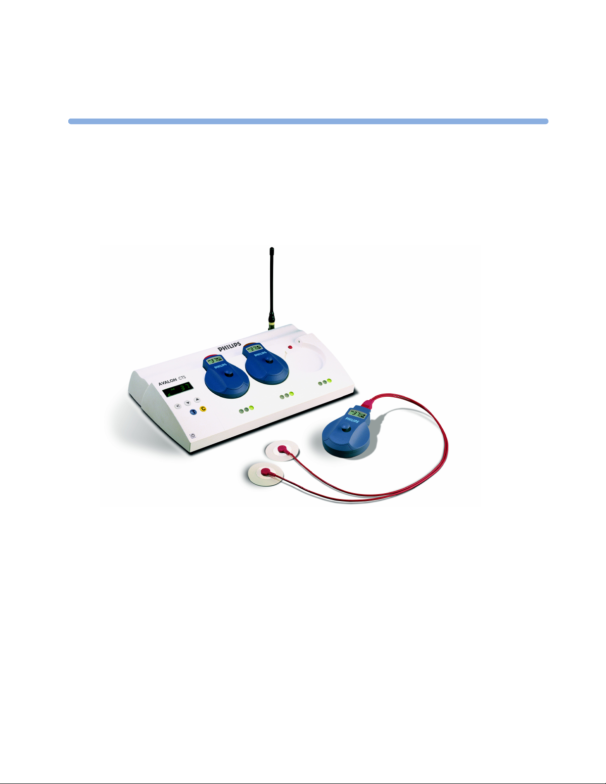
Avalon CTS
Cordless Fetal Transducer System
M2720A
INSTRUCTIONS FOR USE
M2720-9001C
Printed in Germany
August 2004
Page 4

ii
Page 5

1 Introduction 1
Who This Book is For 1
Intended Use 2
Warnings, Cautions and Important Information 2
2 Installation 3
When is the Avalon CTS Customer Installable? 3
When Are Special Configurations Needed? 3
Installation Checklist 4
Checking the Shipment 4
Setting Up the System for the First Time 5
Connecting and Assembling the Standard Antenna 5
Mounting Solutions 6
Connecting the Base Station to a Fetal Monitor 7
How and When to Carry Out Tests 8
Safety Tests 8
Connecting the Base Station to AC Mains 9
System Test 9
What is a Medical Electrical System? 9
General Requirements for a System 9
System Example 10
Contents
3 Basic Operation 11
Base Station 11
Slot Arrangement 13
Transducers 14
MECG and DECG Transducers 15
4 Monitoring a Patient 17
What You Can Monitor 17
Flexible Monitoring 17
Radiated Transmission Power 17
Getting Ready to Monitor 18
Applying a Transducer 18
Using Transducers 19
Changing Between US and DECG Monitoring 19
Monitoring Twins 20
After Monitoring 20
Selecting Stand-by Mode 20
iii
Page 6

Underwater Monitoring 21
About RF Signal Quality 21
Other Monitoring Considerations 22
5 Transducer Behavior 23
Docking Transducers 23
Removing a Transducer from the Base Station 24
Switching Off Transducers 24
6 Troubleshooting 25
Warnings and What To Do About Them 25
Error Handling 27
Error Messages 27
Displaying the Error Messages 28
Solving General Problems 29
Blocked Slots 31
7 Care and Cleaning 33
General Points 33
Cleaning 34
Disinfecting 34
Sterilizing 34
8 Maintenance 35
Battery Care 36
Performance Assurance 36
Parameter Test 36
Toco Transducer Ventilation Knob/Membrane 38
Testing Alarms 38
9 Accessories and Supplies 39
Information on Latex 39
Approved Accessories and Supplies 39
10 Specifications and Standards Compliance 41
General 41
Base Station 41
Transducers 42
Frequency Bands 43
Availability in EU and EFTA Countries 43
Frontends 44
Cables 45
Compatible Fetal Monitors 45
Standards Compliance 45
Safety 45
Electromagnetic Compatibility (EMC) 46
iv
Page 7

EMC Testing 46
Reducing Electromagnetic Interference 47
System Characteristics 48
Electromagnetic Emissions 48
Radio Requirements 48
FCC Compliance (USA only) 49
Canadian Radio Equipment Compliance (Canada Only) 49
Environment 49
ESU, MRI and Defibrillation 50
Protective Earth 51
Maximum Input/Output Voltages 51
Statement of Conformity 51
11 Glossary 53
12 Advanced Configuration 55
Bed Label 55
Theft Protection Level 56
Theft Protection Alert Volume 56
Audible Alert Volume 57
Key Click Volume 58
Acoustical Alarm Default 58
13 Disposal 61
v
Page 8

vi
Page 9
1
1Introduction
Who This Book is For
This book describes how to set up and use the Avalon CTS Cordless Fetal Transducer System with a
fetal monitor. You should be familiar with using medical devices and with standard fetal monitoring
procedures, such as fastening belts and placing transducers. For details of installation procedures and
who should carry them out, see “Installation” starting on page 3.
The information you need to use your fetal monitor and transducers is in the fetal monitor’s
Instructions for Use. Ensure that you read and understand these instructions. Refer also to the
instructions that accompany any accessories and supplies.
The exact appearance of your system, regarding details of product livery, may vary slightly from that
illustrated.
For information on how to service the system, refer to the Service Guide.
1
Page 10

1 Introduction Intended Use
Intended Use
When connected to a compatible fetal monitor, the Avalon CTS Cordless Fetal Transducer System
(M2720A) lets you perform continuous, cordless patient monitoring in the antepartum period and
during labor and delivery.
You can continuously monitor the fetal heart rate (FHR) non-invasively using ultrasound, or invasively
by direct electrocardiogram (DECG), and the uterine activity using an external Toco transducer.
The fetal parameters are measured and transmitted continuously via radio frequency from the
transducer to the base station, eliminating the need for patient cables. The fetal monitor, connected to
the base station, displays and records the parameters.
All the transducers are watertight. You can continuously monitor patients in a bath or shower using the
Toco (M2725A) and the Ultrasound (M2726A) transducers.
The system should only be used by, or under the direct supervision of, a licensed physician or other
health care practitioner who is trained in the use of FHR monitors and in the interpretation of FHR
traces.
Warnings, Cautions and Important Information
WARNING A warning alerts you to a potential serious outcome, adverse event or safety hazard. Failure to observe a
warning may result in death or serious injury to the user or patient.
CAUTION A caution alerts you to circumstances where special care is necessary for the safe and effective use of the
product. Failure to observe a caution may result in minor or moderate personal injury, damage to the
product or other property, and possibly in a remote risk of more serious injury.
On your system, this sign indicates that there is detailed information in this book which
you must read before proceeding with your task.
In this book, graphical symbols (indicators or elements of the base station or transducer
displays) depicted in this way indicate that they are blinking.
© Copyright 1995-2004 Koninklijke Philips Electronics N.V. All Rights Reserved.
2
Page 11

2Installation
This chapter describes how to install the Avalon CTS.
When is the Avalon CTS Customer Installable?
The Avalon CTS is intended to be customer installable under the following conditions:
• The system in its standard configuration is an “out-of-the-box”, standalone system, delivered with
automatic frequency allocation, and is intended to be used with the standard antenna supplied,
giving a line-of-sight operating range up to 100m/300ft.
• There are less than ten stand-alone systems in the institution.
• Connection to an antenna system is not planned.
• No other telemetry devices are used in the institution that can influence, or be influenced by, the
Avalon CTS.
2
• There are no other sources of RF interference that influence the operation of the Avalon CTS.
• There are no country-specific regulations requiring special configuration.
Installation should be carried out by qualified technical personnel.
If you need to mount the Avalon CTS, or use the antenna extension mounting kit (M1361A Option
1AA), see the Service Guide for further details.
When Are Special Configurations Needed?
If one or more of the conditions above are not met, you need a special configuration of the Avalon
CTS. For instance, you may need to:
• Set fixed frequencies when there are other telemetry systems installed in the same institution (always
applies to Japan). This configuration should be carried out by qualified service personnel, either
from the hospital’s biomedical department, or from Philips (see the Service Guide).
• Connect the Avalon CTS to an antenna system because the standard antenna is not sufficient to
cover the area intended for cordless monitoring. Site preparation, antenna system design (including
guidelines for mixed telemetry equipment installations), and installation should be carried out by
qualified service personnel from Philips.
3
Page 12

2 Installation Installation Checklist
Installation Checklist
Use this checklist for customer installable configurations. Refer to the Service Guide and/or contact
Philips Support for installation requirements for all other delivery configurations.
Check Box
Step Task
when Task
Done
Perform initial inspection of delivery, unpack and check the shipment
1
(see page 4)
2 Connect and assemble the antenna (see page 5)
3 Mount the monitor as appropriate for your installation
(see page 6)
4 Connect the base station to the fetal monitor (see page 7)
5 Perform Safety Tests (see page 8)
6 Connect the base station to AC mains using the supplied power cord
(see page 9)
7 Perform System Test as necessary (see “System Test” on page 9)
8 Perform Parameter Test (see “Parameter Test” on page 36)
Checking the Shipment
Unpack the system carefully. Retain the packing materials in case you need to return the system to
Philips or transport your system. Use this table to check your delivery. Inspect all system components,
accessories and supplies for damage before setting up your system.
❏
❏
❏
❏
❏
❏
❏
❏
System Components, Accessories and Supplies Quantity
Base station 1
Ultrasound transducer, cordless, waterproof 1*
Ultrasound transmission gel 1 bottle*
Transducer belts, waterproof, reusable 3*
Toco transducer, cordless, waterproof 1*
ECG transducer 1 (optional)
Antenna with rectangular BNC connector 1
Interface cable, for connection to fetal monitor 1
Power cable 1
Service cable 1
Instructions for Use 1
Documentation CD-ROM (Instructions for Use, Service Guide, and Service Support Tool)1
* Delivered quantity depends on which option you ordered.
4
Page 13
Setting Up the System for the First Time 2 Installation
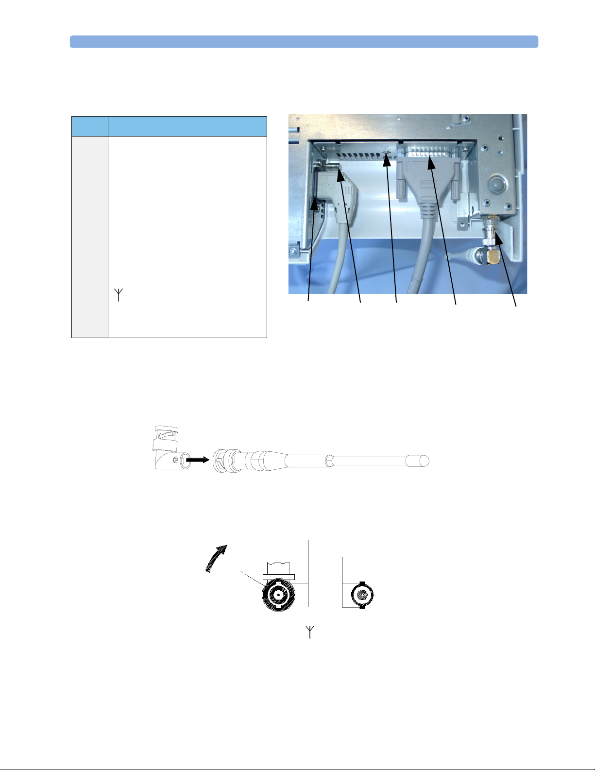
Setting Up the System for the First Time
Item Description
1 Standard AC mains socket.
2 Equipotential Terminal. See “Symbols
on the System” on page 50.
3
Service Socket. 3.5 mm stereo jack for
connecting the Service Support Tool
(service personnel only).
4 Interface to Fetal Monitor. Use the
supplied M2720-61603 cable to
connect the base station to a Series 50
fetal monitor. Do not use any other
cable.
5 Antenna Input. Use supplied
antenna if the base station is not
connected to a hospital’s antenna
system.
(1) (2)
View of the Underside of the Base Station
(3)
(4)
(5)
Connecting and Assembling the Standard Antenna
1
Line up the nodules on the right angle connector with the spaces on the antenna connector.
2 Push in and twist.
3 Connect the antenna
antenna so that the two spaces (B) are positioned at the top and bottom. These fit over the two
notches (C) on the base station antenna socket.
4 Push the antenna onto the input socket at the rear of the base station.
5 Turn the connector collar (A) clockwise until it stops. The antenna should be positioned vertically
to ensure the best operating range.
1
to the base station by turning the connector collar (A) at the base of the
B
C
A
1.Please note that the antenna may differ slightly from the illustration.
5
Page 14
2 Installation Mounting Solutions
To remove the antenna from the base station, turn the connector collar (A) anti-clockwise and pull the
antenna out of the socket.
A remote antenna system, if ordered, is sent separately with its own installation documentation.
Connect the remote antenna cable to the antenna socket at the rear of the base station.
Mounting Solutions
You can mount the Avalon CTS as follows:
• In a standard cart drawer. The base station with docked transducers fits into Philips Carts CL, CX
and CM.
Note: if you mount the base station in a cart or in such a way that the standard antenna cannot be
attached directly to the base station, or does not provide sufficient transmission range, use the
antenna extension mounting kit (M1361A Option 1AA).
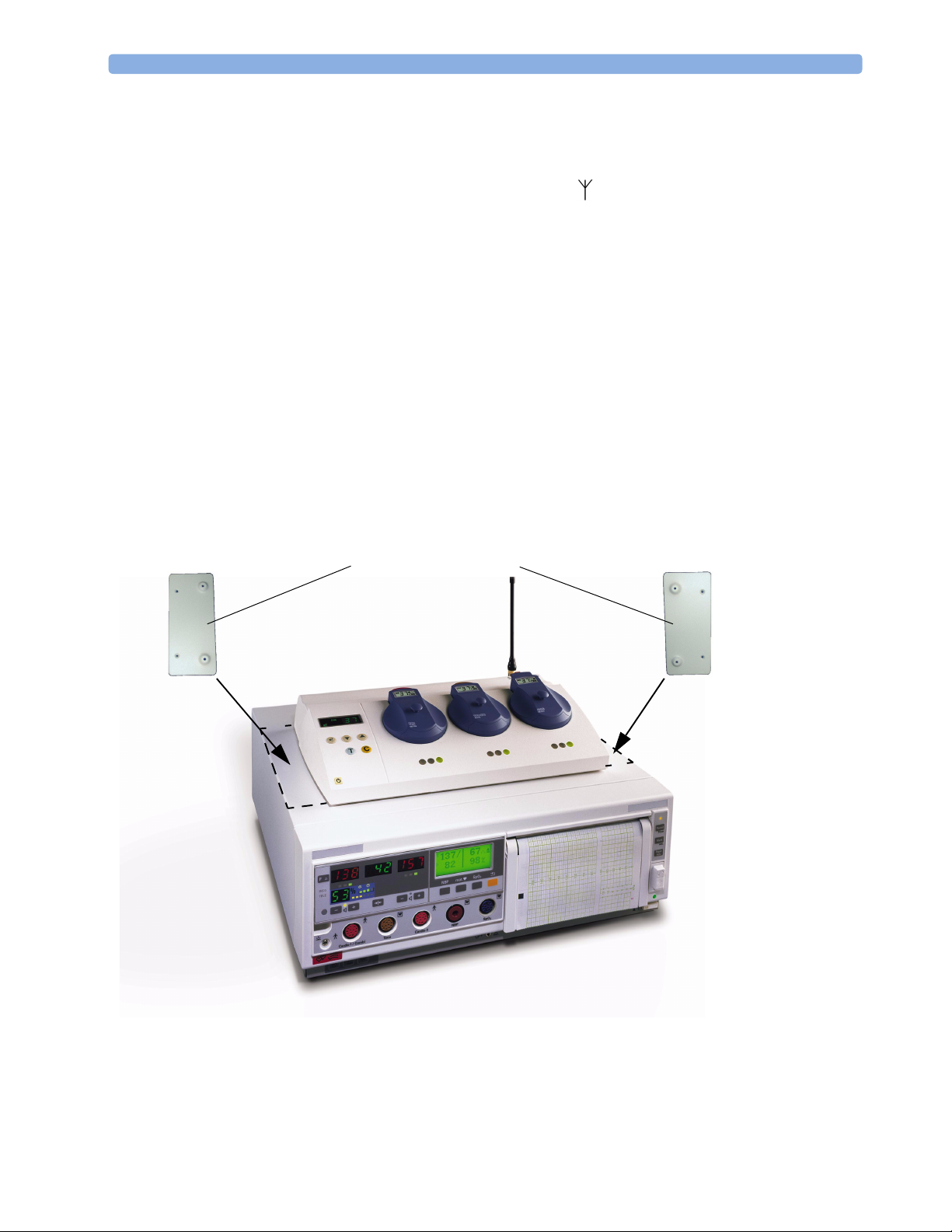
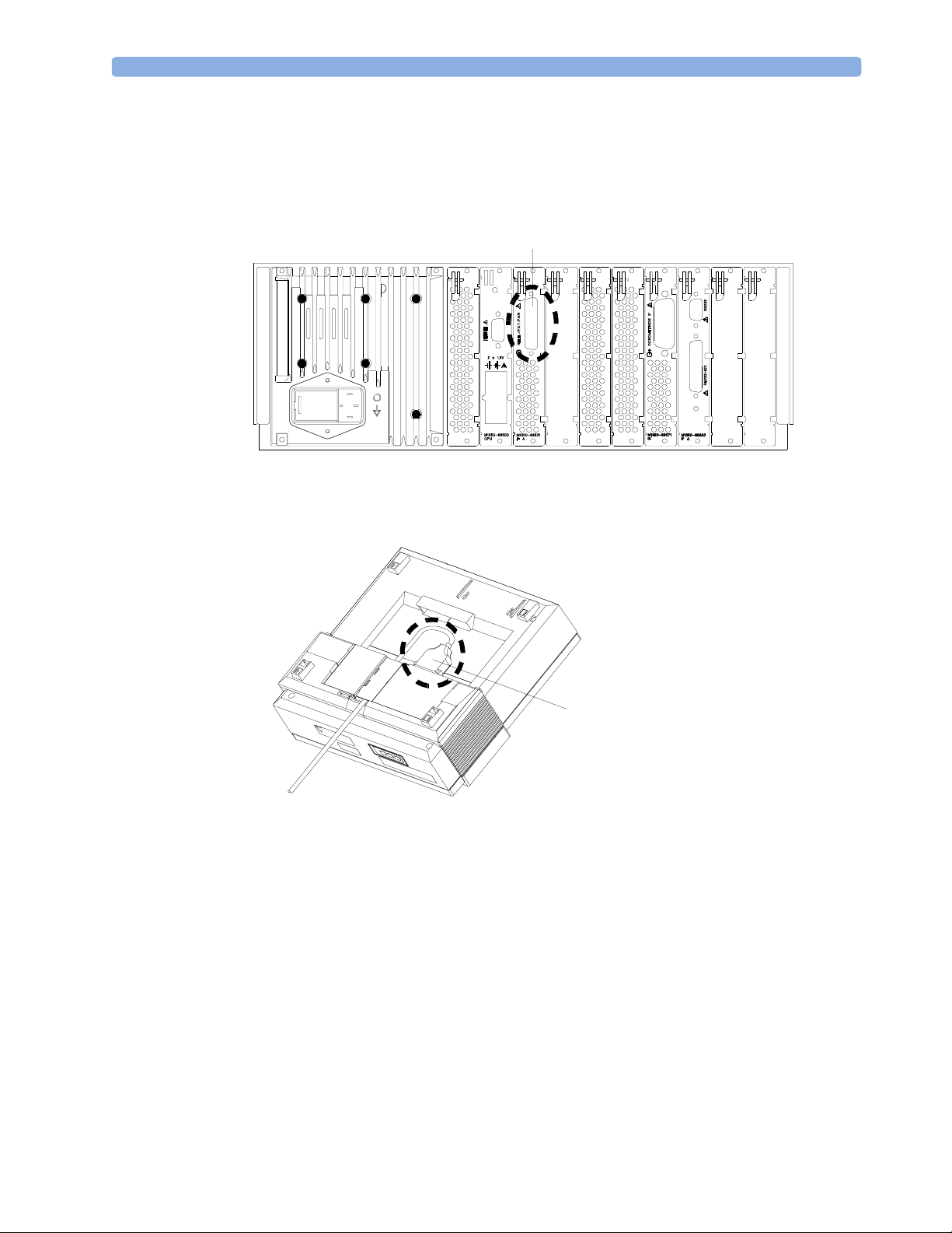
• On top of carts, desks or other flat surfaces using the mounting brackets.
• In a wide variety of situations using the GCX mounting adapter for mounting the base station
(order directly from GCX, part number PH-0042-80).
• On top of Series 50 IX/XM/XMO fetal monitors using the mounting brackets.
Contact your local Philips representative for additional cart mounting options.
Mounting Brackets
Refer to the Service Guide for further details of how to mount your device.
6
Page 15
Connecting the Base Station to a Fetal Monitor 2 Installation
Connecting the Base Station to a Fetal Monitor
1 Connect the interface cable to the fetal monitor interface socket on the base station.
2 Connect the other end of the interface cable to the telemetry socket (B) on the fetal monitor.
B
Series 50 IX/XM/XMO
B
Series 50 A and 50 IP/IP-2
To use the fetal monitor with wired transducers, switch the base station to stand-by. (You do not need
to disconnect the telemetry interface cable.)
7
Page 16

2 Installation How and When to Carry Out Tests
How and When to Carry Out Tests
The following table defines which test or inspections need to be performed, and when they are
required.
Test Test or Inspection to be Performed Test Required for
Which Events?
Visual Inspect the base station, transducers and
cables for any damage.
Are they free of damage?
Power On Power on the base station.
Does the self-test complete successfully? (See
page 18)
Safety Tests (1) to (4) Perform safety tests (1) to (4), as described in
the Service Guide, if required by local
regulations.
Performance Perform the parameter test with all
parameters (see page 36).
Does this test complete without errors?
System Perform the system test according to IEC
60601-1-1, after combining equipment to
form a system (see “System Test” on page 9).
For test and inspection information regarding repairs, upgrades and all other service events, refer to the
Service Guide.
Installation
Preventive Maintenance
Installation
Preventive Maintenance
Installation
Combining or
exchanging system
components
Installation
Preventive Maintenance
Combining system
components
Safety Tests
Details of the safety tests and procedures required after an installation or an exchange of system
components are described in the Service Guide.
WARNING Safety test requirements are set acccording to international standards, such as IEC/EN 60601-1 and
IEC 60601-1-1, their national deviations, such as UL2601-1, CAN/CSA-C22.2 No. 601.1-M90 and
No 601.1-S1-94, and specific local requirements.
The safety tests detailed in the Service Guide are derived from international standards but may not be
sufficient to meet local requirements.
CAUTION The correct and accurate functioning of the equipment is ensured by the successful completion of the
safety tests, performance test, and the system test.
8
Page 17

Connecting the Base Station to AC Mains 2 Installation
Connecting the Base Station to AC Mains
WARNING This equipment is intended for use only within healthcare facilities. It is not suitable for use in
domestic establishments and in establishments directly connected to a low voltage power supply
network, which supplies buildings used for domestic purposes.
Do not use additional AC mains extension cords or multiple portable socket-outlets. If a multiple
portable socket-outlet without a separation transformer is used, the interruption of its protective
earthing may result in enclosure leakage currents equal to the sum of the individual earth leakage
currents.
Connect the base station to the AC mains using the supplied power cord.
Important for users in the USA: Before connecting the base station to a 240 V AC mains supply system
(instead of the usual 110 V), ensure that the system is a center-tapped single phase circuit.
If the AC power fails, the base station’s power failure recovery system ensures that, after the return of
power, the system resumes normal operation automatically.
System Test
After mounting and setting up a system, perform sytem safety tests.
What is a Medical Electrical System?
A medical electrical system is a combination of at least one medical electrical device and other electrical
equipment, interconnected by functional connection or use of a multiple portable socket-outlet.
General Requirements for a System
After installation or subsequent modification, a system must comply with the requirements of the
system standard IEC/EN 60601-1-1. Compliance is checked by inspection, testing or analysis, as
specified in the IEC 60601-1-1 or in this book.
Medical electrical equipment must comply with the requirements of the general standard IEC/EN
60601-1, its relevant particular standards and specific national deviations. Non-medical electrical
equipment shall comply with IEC and ISO safety standards that are relevant to that equipment.
Relevant standards for some non-medical electrical equipment may have limits for enclosure leakage
currents higher than required by the standard IEC 60601-1-1. These higher limits are acceptable only
outside the patient environment. It is essential to reduce enclosure leakage currents when non-medical
electrical equipment is to be used within the patient environment.
WARNING Do not connect any devices that are not supported as part of a system.
9
Page 18
2 Installation System Test
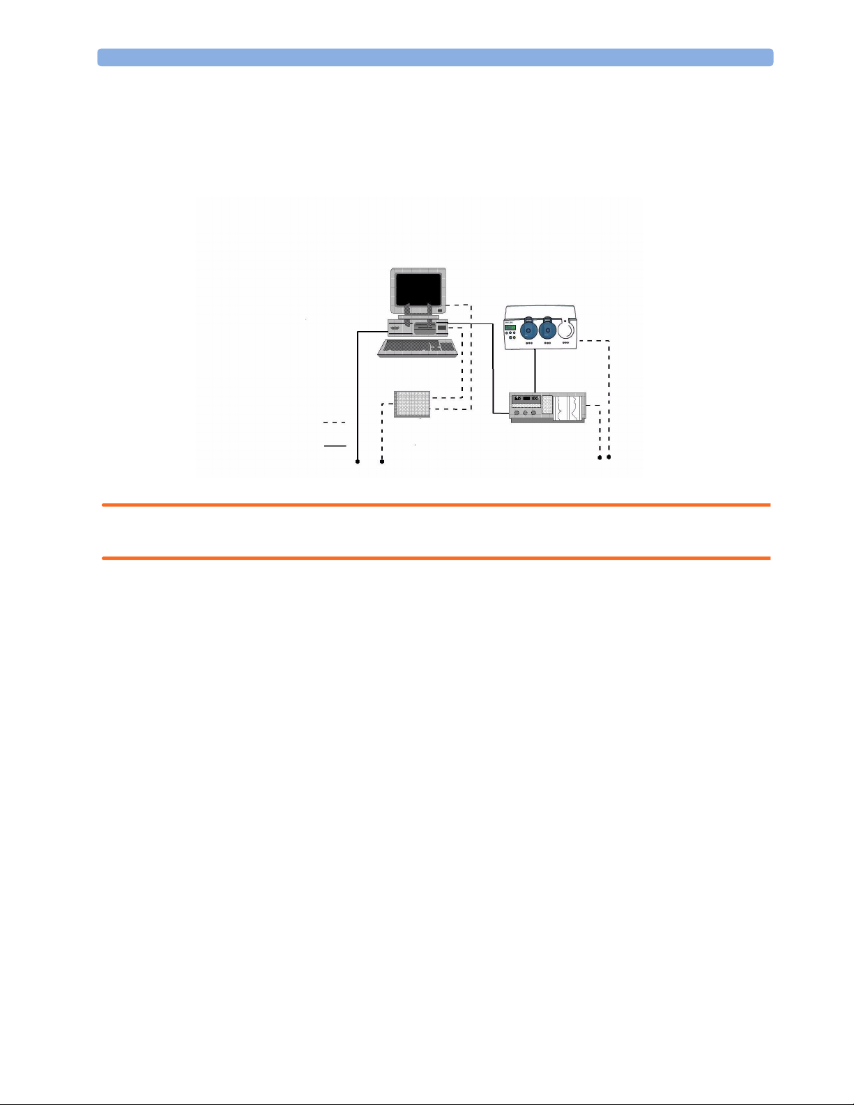
System Example
This illustration shows a system where both the medical electrical equipment and the non-medical
electrical equipment is situated at the patient’s bedside.
Non-Medical Devices
Personal
Computer
Distance to patient
must be >= 1.5m
Isolation
Transformer
Key:
Power cables:
Data cables:
WARNING Any non-medical device placed and operated in the patient’s vicinity must be powered via an approved
Medical Devices
Avalon CTS
Fetal Monitor
separation device.
If the personal computer (or any other non-medical electrical device) is situated outside the medically
used room, you must take measures to reduce leakage currents, such as providing an additional
protective earth, a non-conducting enclosure, or a separation device.
10
We highly recommend using a separation device whenever you connect non-medical electrical
equipment.
Page 19
This chapter describes the operational features of the Avalon CTS base station and transducers,
including details of keys, displays and indicators.
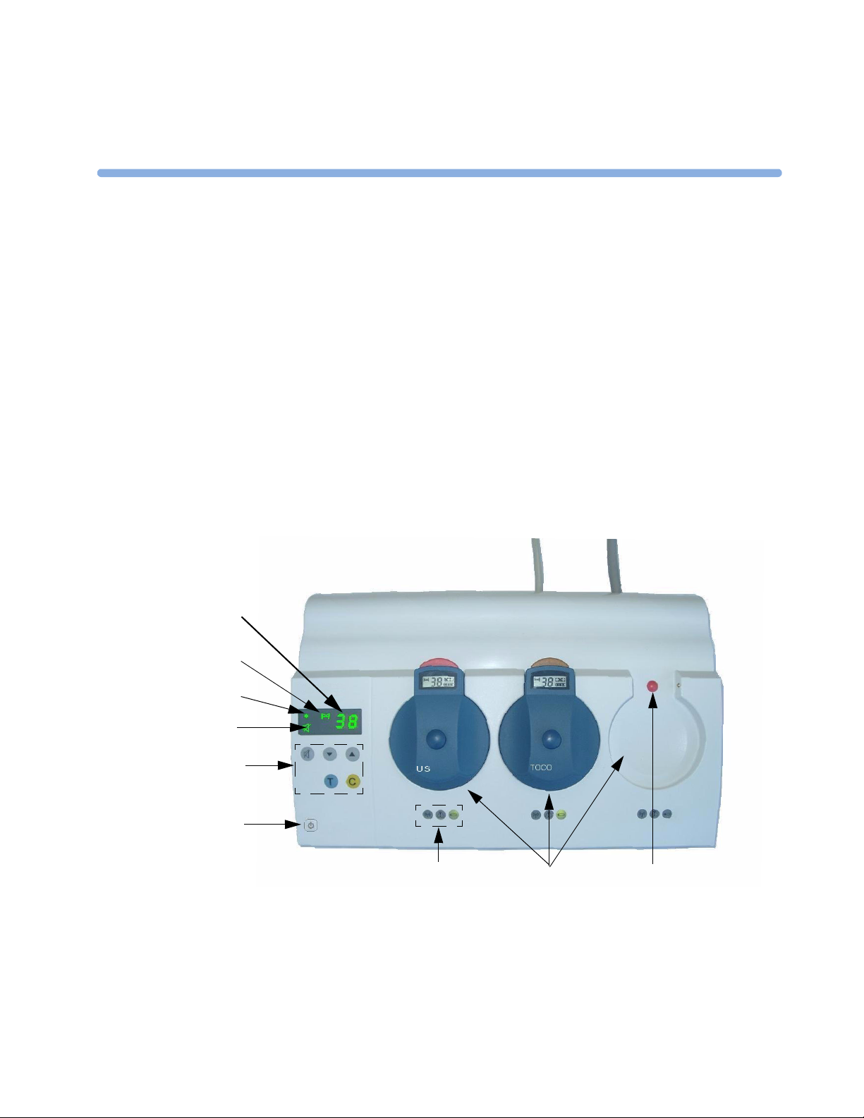
Base Station
Your base station is shipped with a default bed label. This is the last two digits of the serial number.
You can change this to any two-digit value between 00 and 99 (see page 55). We recommend that you
give each base station in the hospital its own bed label. This lets you know to which base station an
active transducer belongs. Normally, you would not have to change the bed label. The base station
display and a registered transducer each display the bed label and bed symbol.
3
3Basic Operation
1
2
3
4
5
6
7
8
9
11
Page 20
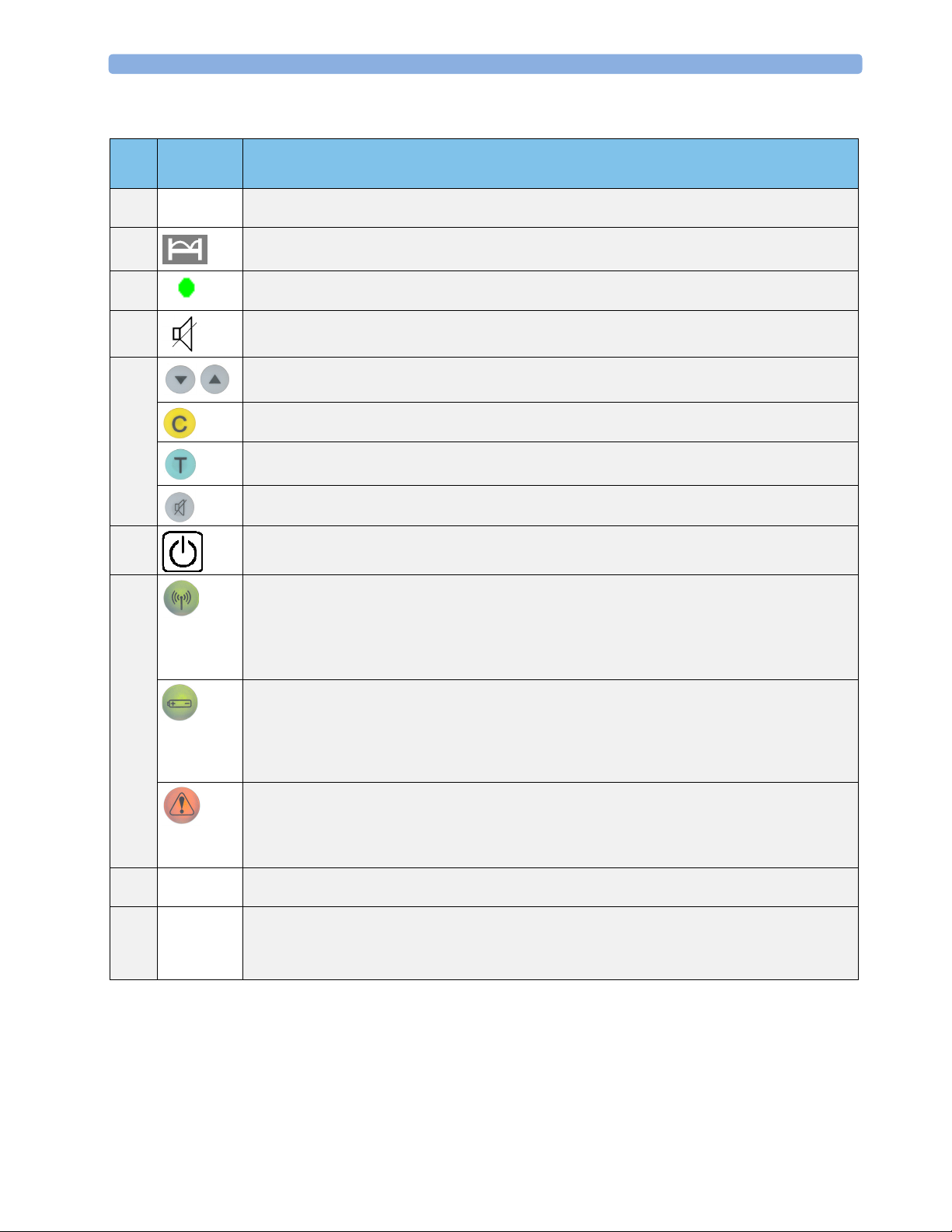
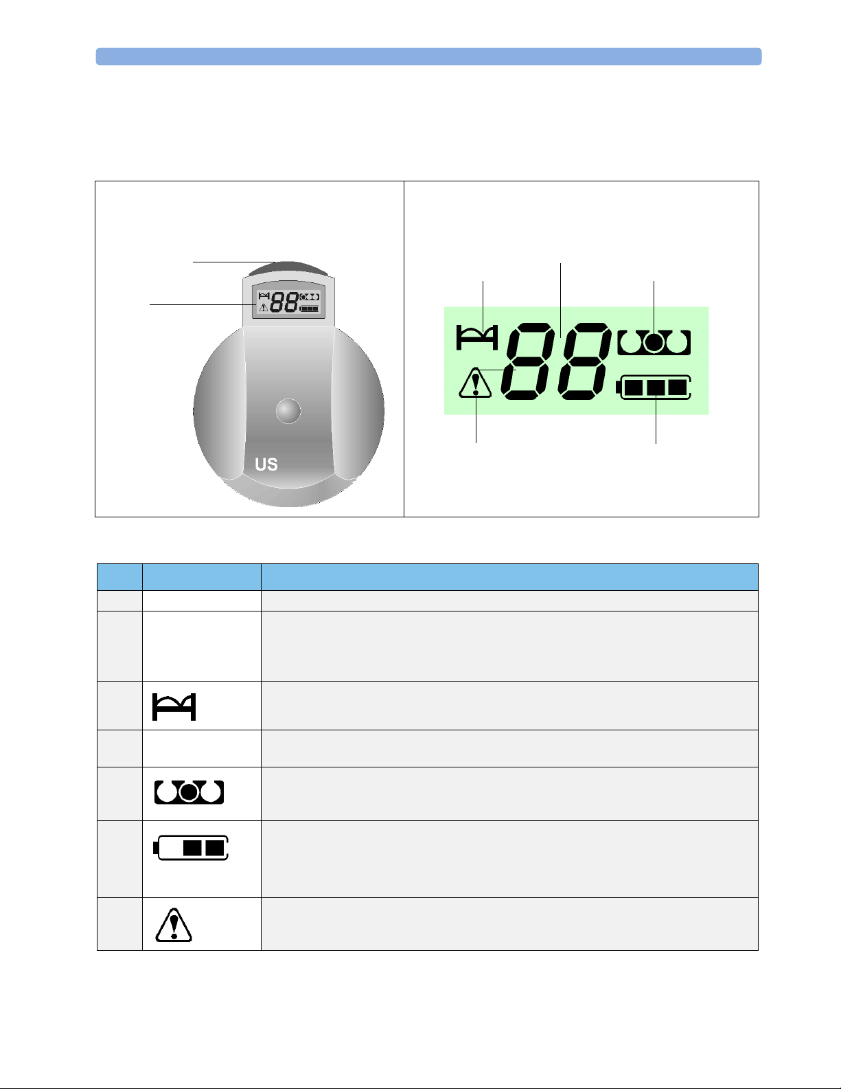
3 Basic Operation Base Station
Item Key or
Comments
Symbol
1Numeric
display
2 Bed Symbol: lights to show that the bed label (not error code) is currently shown in the numeric display.
3 Power-on or Stand-by LED. When the base station is connected to the mains, even in stand-by mode,
4 Audible Alerts Off Symbol: Indicates that audible alerts are off.
5 Navigation Keys to move through the configuration setting menus.
6 On/Stand-by: switches between stand-by (charge only) and On (operating mode).
7
8Docking
Slots
9Docking
slot color
code
indicator
Two-digit display: shows unique base station identification number (bed label), error and warning codes,
configuration settings.
transducer batteries charge continuously.
Function Key: multi-function key for clearing blocked slots, acknowledging alarms, and confirming
configuration changes.
Test Key: press and hold down to test all system components and links to fetal monitor. Numerics are
displayed/recorded on the fetal monitor.
Audible Alerts Off: switches alerts on and off.
RF Link Indicator
Continuously on - transducer removed and active.
Blinking together with the Warning Indicator - indicates that signal is too weak because patient is out of
receiving area, or interference from stronger RF signal, or transducer has auto shutdown due to low
battery.
Battery/Ready Indicator
Continuously on - indicates that the transducer is ready to use. It goes out as soon as you remove the
transducer from its slot.
Blinking together with the Warning Indicator shows that the battery of the active transducer which belongs
to this slot is nearly empty.
Orange Warning Indicator
Slot, or the transducer which belongs to the slot, requires attention.
Usually, this warning indicator comes on together with another blinking symbol, that is, the battery symbol
or the RF link indicator.
Store, charge and register transducers. Slot is color coded to match transducer color. Charges batteries
when transducer is docked, even in stand-by.
Red - US or optional ECG transducer with DECG or MECG adapter cable.
Brown - Toco
Neutral colored optional ECG transducer (without adapter cables attached) can go in Slot 1 or Slot 3.
12
Page 21
Slot Arrangement 3 Basic Operation
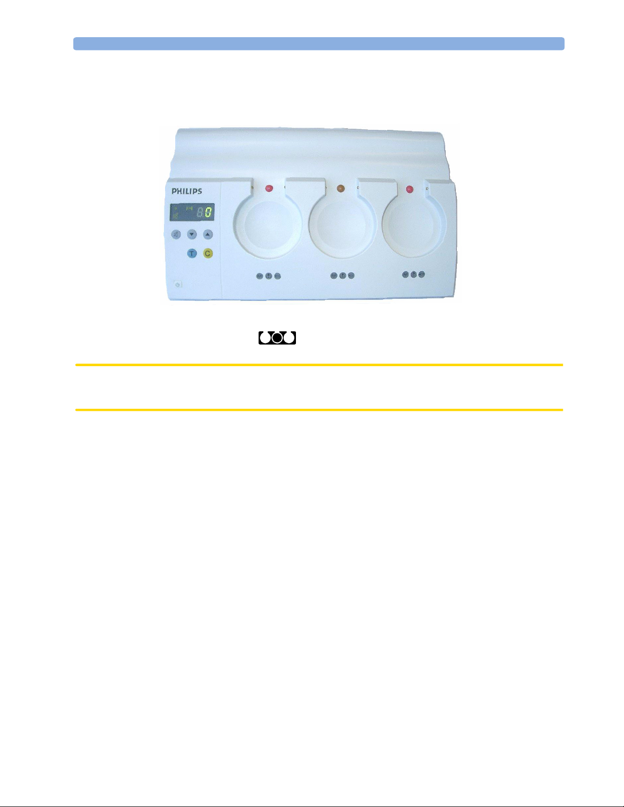
Slot Arrangement
You can use transducers in the following slot positions:
Slot 1
Cardio-1
Slot 2
US
or
Toco
ECG
Twins monitoring is not possible.
The slot position indicator on the transducer display (here showing Slot 2, Toco) always
tells you in which slot to dock the active transducer after use.
CAUTION The base station generates a magnetic field. Do not store magnetic media (such as magnetic tapes and
disks, identity cards or credit cards with magnetic strips) near to the base station, as the data may be
damaged.
Slot 3
Cardio-2Toco
US
or
ECG
13
Page 22
3 Basic Operation Transducers
Transducers
You can switch a transducer on, charge its battery, and register it to a base station only when it is
docked in a base station slot.
2
3
4
5
1
7
(Shows Toco transducer)
6
Item Key or Symbol Comments
1 Display Displays bed label, error codes, and operating conditions.
2 Take-out aid Colored aid makes removal of transducer easier and helps you to ensure correct
transducer placement in docking slot. Red for US, brown for Toco, blue for ECG (can
go in any slot when adapter cables are not attached and the connector socket is colorcoded red).
3 Indicates that the numeric display is showing the bed label.
4 Numeric display Shows bed label number during normal operation, and if an error occurs, the error code
number.
5 The filled dot indicates from which docking slot you removed the transducer, that is, the
one to which the transducer is registered. Helps you to find the correct docking slot
when you replace the transducer in the base station.
6 Indicates available battery capacity. Does not predict remaining operating time, as
capacity of fully-charged batteries varies.
If there is only one segment in the display, you have less than one hour’s operating time
left.
7 Indicates that the number shown in the numeric field is a warning code. During normal
use you see only the bed symbol.
14
Page 23

MECG and DECG Transducers 3 Basic Operation
MECG and DECG Transducers
1
4
5
2
6
3
MECG (M2727A) DECG (M2727A)
1 Electrodes (40493E) 4 Disposable electrode (M1349A)
2 MECG Adapter Cable
(M1363A)
3 Red ECG connector socket 6 Red ECG connector socket
You can use standard MECG (M1363A) and DECG (M1362B) cables with the M2727A ECG
transducer. You can dock the ECG transducer without an MECG or DECG adapter cable in Slot 1 or
Slot 3.
DECG/MECG measurement allows two lead ECG but no diagnostic MECG. ECG inputs are not
defibrillator resistant.
WARNING Shock hazard!
NEVER dock an ECG transducer (either in DECG or MECG mode) in a base station slot if there
are electrodes attached to the patient.
Do not use the ECG transducer under water. Although it is watertight, the functionality of the ECG
transducer under water has not been validated for DECG and MECG measurements.
5 DECG Adapter Cable (M1362B)
15
Page 24

3 Basic Operation MECG and DECG Transducers
16
Page 25

4Monitoring a Patient
See your fetal monitor’s Instructions for Use for details of how to monitor fetal heart rate (FHR) and
uterine activity, including how to apply transducers and transducer belts. Refer also to the instructions
that accompany any accessories and supplies (for example, fetal scalp electrodes).
The device is intended to monitor one mother and her fetus.
What You Can Monitor
You can monitor:
• the fetal heart rate, using either ultrasound or direct ECG.
• uterine pressure, using the Toco transducer.
• maternal ECG using the ECG transducer.
4
While monitoring maternal ECG, you can monitor the fetal heart rate using ultrasound, but not using
DECG, as the ECG transducer is already being used to monitor the mother’s heart rate.
You cannot monitor two fetal heart rates simultaneously. Only one fetal heart rate is supported at a
time.
Flexible Monitoring
Your Avalon CTS provides highly reliable, cordless patient monitoring, giving the patient complete
freedom of movement while being monitored. While this represents a major contribution to the
comfort of the patient, be aware that when a patient is mobile, monitoring of the fetal heart rate may
be slightly less reliable than a traditional wired system where patient movement is limited.
Radiated Transmission Power
The Avalon CTS provides all the benefits and flexibility of cordless operation, but does so with an
effective radiated transmission power significantly less than that of a typical remote controlled child’s
toy.
17
Page 26

4 Monitoring a Patient Getting Ready to Monitor
WARNING Explosion hazard:
– Do not use in the presence of flammable anesthetics.
– Do not dry equipment using heating devices such as heaters, ovens (including microwave ovens),
hair dryers and heating lamps.
Getting Ready to Monitor
WARNING Always check the condition of all parts of the system before use. Do not use any items that show signs
of damage, or in the case of a transducer, moisture or condensation behind the LCD window.
For cordless monitoring, ensure that any wired transducers are disconnected from the fetal monitor.
1. Connect the base station to the AC power supply.
2. Press . The base station:
– sounds a “welcome” beep
– performs a display selftest, briefly switching on all display elements
– displays the bed label together with the bed symbol
3 Ve r if y that “TELE” is illuminated on the fetal
monitor.*TELE* appears on the fetal monitor’s recorder
strip every time you switch on the recorder or change a
mode.
4 Wa it until the right-hand lamp of the slot goes to
“TELE” is
illuminated
showing
active connection
to fetal monitor
green.
5 Remove the transducer.
If theft protection is on, press while removing the transducer. If you do not, the base station
sounds an audible alert.
The right-hand lamp of the slot goes off, and the left-hand lamp
long as you monitor.
Monitor your patient.
6
Applying a Transducer
The transducers may pre-warm close to body temperature after they have been docked in a base
station connected to AC mains power. This is normal. Please advise your patient before applying the
transducer.
CAUTION Do not drop the transducers, as they may be damaged, and may no longer be watertight.
MEC
TELE
lights, and stays on as
18
Do not use velcro belt adapter plates, as they can damage the transducers.
Page 27

Using Transducers 4 Monitoring a Patient
Apply the active transducers to the patient in accordance with the instructions given in the fetal
1
monitor’s Instructions for Use.
2 Ve ri fy that there is a good signal connection between the base station and the transducers.
should be continuously on. If it is blinking, in conjunction with the warning symbol then there is a
reception problem. You see this . See “Troubleshooting”.
3 Ve ri fy that: “TELE” is illuminated on the fetal monitor.
Using Transducers
The fetal heart rate always appears on the left Cardio channel display of the fetal monitor, whether
you are using ultrasound or DECG. The MECG parameters are always assigned to the right Cardio
channel of the fetal monitor.
Changing Between US and DECG Monitoring
If you have been monitoring using ultrasound and want to change to DECG, or the other way round,
the following table informs you what to do.
Changing from US to DECG monitoring Changing from DECG to US monitoring
1 Dock the US transducer. 1 Disconnect the DECG adapter cable
M1362B and the fetal scalp electrode from
the ECG transducer.
2 Take out the ECG transducer when the
lamp
3 Connect the DECG adapter cable
M1362B and the fetal scalp electrode to
the ECG transducer.
4 Start DECG monitoring. 4 Start ultrasound monitoring.
for that slot is green.
2 Dock the ECG transducer.
3 Take out the US transducer when the lamp
for that slot is green.
If two transducers for monitoring the FHR are active at the same time transmitting to the same base
station, error message E9 is shown on the base station display . Clear the error by
docking one of the transducers.
The FHR 1 field of the fetal monitor display shows
Err alternating with the error number 9 which
means invalid telemetry mode. Printing of the fetal heart rate trace on the CTG recorder is stopped.
MECG
TELE
19
Page 28

4 Monitoring a Patient After Monitoring
Monitoring Twins
Cordless monitoring of twins is not possible. If your fetal monitor supports twin monitoring, to
monitor twins:
– Switch off the base station.
– Connect standard transducers with cables to the fetal monitor, and continue monitoring.
After Monitoring
We recommend that you always leave the base station connected to AC mains.
Clean the transducers and dock them in the base station slot following the color code. You hear a ‘click’
when a transducer is properly seated.
Always disconnect ECG cables before docking ECG transducers.
If you want to monitor using wired transducers, switch the base station to stand-by (see below).
If you want to store the transducers outside the base station, or transport them, switch them off first.
To switch off a transducer:
a. Switch the base station to stand-by (see below).
b. Remove the transducer.
Selecting Stand-by Mode
1 Return any active transducers to their associated docking slots.
2 Press . The base station display shows only the power-on/stand-
by
LED.
The transducer LCD shows only the battery symbol to indicate battery
charging.
In stand-by mode, the base station:
– accepts any transducer in any operational state.
– accepts active transducers from another base station for charging. The other base station generates
a signal loss alarm in this case.
20
Page 29

Underwater Monitoring 4 Monitoring a Patient
Underwater Monitoring
WARNING Never immerse the base station in liquid. You must protect it against water sprays or splashes. Place
the base station where there is no chance of contact with, or falling into water or other liquid.
Toco Baseline drift: The accuracy specified for baseline drift cannot be guaranteed for underwater
usage. When using transducers under warm water the temperature increase causes a significant baseline
change due to internal pressure increase. The depth under water at which the Toco transducer is used
also has an effect on the Toco baseline, as the water pressure increases with depth. After immersion,
allow one to two minutes for the pressure to stabilize, then adjust the Toco baseline (between
contractions), and check it frequently.
Signal loss/interference: When using the transducers underwater, signal loss or interference may occur.
CAUTION Avoid the use of pulsating water jets in the bath or shower while monitoring, as these can be
misinterpreted as an incorrect (or totally artificial) heart rate.
All Toco (M2725A) and ultrasound (M2726A) transducers are waterproof, fulfilling the watertight
criteria of IP 68 (immersion to a depth of 0.5 m for five hours), according to IEC 60529. You can use
them to monitor patients in a bathtub or shower.
Cordless transmission distances are shorter when monitoring under water. A metal bathtub is likely to
further reduce the operating range.
About RF Signal Quality
Signal transmission can be disturbed when:
– the patient is out of range of the receiving area.
– there is interference from another, possibly stronger, RF signal (a broadcasting station, for
instance).
– the patient is near material that absorbs electromagnetic waves (for example, metal-reinforced
concrete, elevator doors) or the base station antenna is in an enclosed metal rack.
21
Page 30

4 Monitoring a Patient Other Monitoring Considerations
Other Monitoring Considerations
WARNING • Ensure that the conductive parts of the fetal scalp electrode and the maternal legplate electrode do
not contact other conductive parts, including earth.
• Indication of the heart-rate may be adversely affected by the operation of cardiac pacemaker pulses
or by cardiac arrhythmias.
• During ambulant FHR monitoring, the chance of losing the signal or detecting the maternal heart
rate is higher than during stationary monitoring. The frequency of the patient's walk may be
detected, and mistaken for a FHR signal.
• Check the mother’s pulse periodically during monitoring and compare this with the FHR signal.
Beware of mistaking a “doubled” maternal heart rate for FHR. In the case of a dead fetus, there is a
risk that the maternal heart rate is monitored and misinterpreted as the fetal heart rate. Therefore,
the simultaneous monitoring of maternal heart rate (preferably, the maternal ECG) is encouraged.
• Do not interpret maternal movements as fetal movements.
• Artefacts: FMP artefacts are generated during fetal heart rate searching by changing the transducer
position, therefore the Series 50 fetal monitors enable the FMP only after detecting a valid heart rate
signal for several seconds.
Disable Fetal Movement Profile Processing (FMP) at the fetal monitor (FMP off ) if the mother is
walking.
• Gaps and maternal heart rate detection can occur:
– if the transducer is not correctly positioned.
– due to the pulsation of uterine blood vessels.
– if the fetus moves.
CAUTION Performing ultrasound imaging or Doppler flow measurements in conjunction with ultrasound fetal
monitoring may cause false readings of FHR (recording of the trace may deteriorate).
22
Page 31

5Transducer Behavior
Additional information regarding transducer behavior is given in this chapter.
Docking Transducers
When the base station is on...
1 When you dock a transducer in an active base station, it performs a
2 The transducer display shows the slot indicator, battery symbol, and
5
test on itself, briefly switching on all display elements.
the two segment bars for a few seconds.
3 The transducer is registered to the base station slot. The system gives
the transducer a bed label identity. The two segment bars move up and
down in the numeric display, as the system searches for a channel.
Do not remove the transducer during registration (while the two
segment bars are still visible), as this starts the transducer shutdown
process.
4 When the bed label on the transducer matches the base station,
registration is complete, and you can now use the transducer.
Depending on your system’s configuration, you may notice that the
transducer display sometimes reverts to the channel search stage shown
in step 3. This happens when the system detects that a channel is
already occupied or that there is some interference on that channel,
and the system searches for an alternative, free channel. This is part of
normal operation. The transducer is then registered as usual.
If channel allocation is not possible due to lack of free channels, then
Out of free channels warning appears (see “Warnings and What To
the
Do About Them” on page 25).
23
Page 32

5 Transducer Behavior Removing a Transducer from the Base Station
When the base station is in stand-by...
When you dock a transducer with the base station in stand-by, the
transducer also switches to stand-by mode. The LCD shows only the
battery symbol in the bottom right hand corner. This indicates that
the batteries are charging.
Removing a Transducer from the Base Station
1 Ensure that the required transducers are ready to use (a bed label matching
that of the base station is displayed in the LCD window).
2 When theft protection is off, pull up on the take-out aid to remove the
transducer.
If theft protection is on:
Press while removing the transducer. If you do not, the base station sounds an audible alert.
To silence the alert, either re-insert the transducer into its docking slot or disconnect the base station
from the AC power. If you do not acknowledge it, the alert stops after one minute. See “Theft
Protection Level” on page 56 for more details.
3 The transducer starts transmitting automatically and you can prepare to monitor straight away.
Switching Off Transducers
You should switch off transducers before storing or transporting them, so that the battery does not
discharge.
To switch off a transducer:
1 Dock the transducer and switch the base station to stand-by.
2 Remove the transducer.
24
Page 33

6Troubleshooting
This chapter helps you recognize system error messages and problems you may encounter while using
the system.
Warnings and What To Do About Them
Base Station Warnings: blinks, alone or with lamps on either side.
means lamp is either off or continuously on.
means audible alert, if set. Press to silence.
Transducer Warnings: blinks together with the symbol representing the problem source.
6
If you get this warning...
...On base station... ...On transducer
...Do this...
Dock transducer to recharge
battery, or replace
transducer with a charged
transducer. If problem
persists, change transducer
battery. (Also see Service
Guide.)
Check that transducer is
active and within range.
Check antenna connection.
Press for two seconds,
to release blocked slot.
See “Blocked Slots” on
page 31.
Possible
Reasons
Battery in the
transducer is
exhausted, leading
to a shutdown and
signal loss.
RF signal distortion.
Tr a ns d uc e r o u t o f
range.
Automatic
transducer
shutdown.
Slot has lost RF
signal with own
active transducer.
Active transducer
from another base
station is docked in
this slot.
25
Page 34

6 Troubleshooting Warnings and What To Do About Them
If you get this warning...
...On base station... ...On transducer
Example bed label
Example bed label
...Do this...
This slot has an active
transducer! Dock this one
first to stop transmission.
Or
Return transducer to its
own base station.
Call Support.
If active ECG transducer,
connect cable.
Place transducer in slot
according to position
indicated by the dot.
As the transducer is not
working, this error condition
is indicated on the base
station by the warning
indicator.
Possible
Reasons
System rule: an active
monitoring link can
never be broken by
docking the
transducer in the
wrong base station.
Tr a n s d u c e r
registration is not
possible due to lack
of free RF channels.
ECG transducer is
waiting for you to
connect a MECG or
DECG adapter cable.
Transducer is in the
wrong slot. Color
code does not match
or an active
transducer is placed
in the wrong slot.
Communication
between base station
and inserted
transducer is not
possible.
Theft Protection Alert
26
Take out the transducer and
wait for shutdown, and then
dock it again.
Check transducer/docking
slot contacts.
Unplug system. Switch it on
again.
If problem persists, call
Support.
Press to silence.
Correct transducer
removal procedure
was not followed.
See “Removing a
Transducer from the
Base Station” on
page 24.
When base station is in stand-by mode:
– all audible warnings are disabled (except the theft protection if it is enabled).
– only the power on/stand-by LED (base station) and the battery indicator (transducer) are active.
Page 35

Error Handling 6 Troubleshooting
Error Handling
Error messages appear if a malfunction causes any part of the system to become unusable, which may
affect the safety and performance of the system.
When there is a fault in a transducer, the error code is shown in the transducer’s LCD window. If the
base station develops a fault, this is shown on the base station display. The only exception to this is
when a transducer is completely inoperative. In this case, as it is not possible for the transducer to
display the error, this is registered on the base station (the warning symbol
blinks).
It is highly recommended that the system is inspected by a qualified service engineer and the cause of
the problem is identified and corrected.
Error Messages
Error*
Number
E0 Unknown errors Unclassified error. The base station restarts every ten seconds and
E1 Device failure General hardware or software
E2 Transducer inoperative Transducer hardware defect.
E3 Incompatibility error Incompatible software
E4 Battery charging not
E5 to E8 Reserved for future
E9 Mode conflict Two US, DECG or MECG
Error
and Type
possible
implementation.
Possible Reasons Comments
the system cannot be used. Refer to qualified
service personnel.
The system cannot be used. Refer to qualified
device failure.
This does not affect the
operation of the system as a
whole, but is restricted to the
malfunctioning transducer.
revision.
Battery defect (charge level of
the battery does not change).
Debugging and service-related
information.
transducers out of the same
base station are active.
service personnel.
Transducer related error is displayed on the base
station, since the transducer display is not
working.
Try to reset the transducer. Switch the base
station to stand-by, then remove the transducer
to shut it down. Then dock it again and switch on
the base station.
If the transducer repeatedly fails to reset, replace
the transducer.
Refer defective transducer to qualified service
personnel.
Incompatibility error is displayed if an
unsupported transducer is placed in an empty
slot. Use only supported transducers.
Battery damage caused by excessive discharge.
For tips on battery maintenance, see “Battery
Care” on page 36.
For battery replacement, refer to the Instruction
Sheet, “Removing and Replacing the Transducer
Battery” that accompanies the Battery
Replacement Kit M2720-64001.
Refer to qualified service personnel.
Twin or dual ECG monitoring is not supported.
*If you cannot solve the problem, refer to qualified service personnel.
27
Page 36

6 Troubleshooting Displaying the Error Messages
Displaying the Error Messages
Error messages are prefixed with a letter E in the two-digit numeric field either on:
• the base station display (for serious errors or minor errors caused by the base station)
or
• the transducer displays.
Examples of how error messages are displayed:
Error
Code
E1 Base station failure
E1 Transducer failure
Error Type
Displays
Base station Transducer
The base station will perform a cyclic
reboot (every 10 seconds) and the
system cannot be used.
The base station
display shows the
bed label. The warning light blinks.
If the transducer is completely inoperative,
its LCD is blank, so the only way to show
this is on the base station. The warning
symbol blinks additionally in this
case.
The transducer display may either show
nothing or the pattern for
unprogrammed transducers, depending
on the program state at the time of error
detection.
If possible, the LC display shows the
error number. Depending on the failure
severity, the transducer may perform a
cyclic reboot (every 10s).
28
Page 37

Solving General Problems 6 Troubleshooting
Solving General Problems
Problem Possible Causes Solutions
The Telemetry Indicator Lamp on
the fetal monitor does not light
when the monitor and the base
station are switched on.
Base station Power On Light does
not light when the base station is
switched on.
Cordless monitoring is not
possible.
Signal loss indicator on the base
station is still lit when the
transducer is active.
Battery Low Light lit on base
station.
Incorrect interface connection
between the monitor and the base
station.
Faulty interface cable.
Power cable not plugged into the
power supply.
Insufficient AC power cable
contacts (loose cable).
Fuses need replacing.
Wired transducers are connected
to the fetal monitor.
Base station and transducer do not
have the same bed label.
Standard Antenna: Antenna not
connected correctly.
Remote Antenna: Antenna cable
not connected correctly to the base
station.
Transducer is out of range.
Transducer is malfunctioning or
damaged.
RF interference from an external
source, such as a broadcasting
station, or other telemetry devices.
Low battery power.
Power in batteries is low. There is
less than one hour of operating
capacity left.
Follow the instructions in Service Guide for
details on how to connect the monitor to
the base station.
Replace interface cable.
Plug in and switch on.
Check power cable connection. Refer to
qualified service personnel.
Replace fuses. See Service Guide.
Unplug wired transducers from the fetal
monitor.
Use the bed label to identify to which base
station the transducer belongs. See also
“Blocked Slots” on page 31.
Check antenna connection.
Test the antenna system by bringing the
transducer close to the base station. If the
transmission is good, then the antenna
system is not functioning properly. Refer
the problem to qualified service personnel.
Determine the effective operating range of
the system in your particular environment,
and inform the patient to stay within this
area while monitoring takes place.
Replace the transducer.
Move the transducer away from the
suspected source, to a different location,
and check for improvement.
Charge batteries.
Charge the batteries.
If battery performance is still not
satisfactory after charging, carry out the
battery check (see Service Guide).
All three lights blink on base
station.
Battery in the transducer is
exhausted, leading to a shutdown
and signal loss.
If necessary, change the battery in the
transducer. (Refer to the Instruction Sheet,
“Removing and Replacing the Transducer
Battery” that accompanies the Battery
Replacement Kit M2720-64001.)
29
Page 38

6 Troubleshooting Solving General Problems
Problem Possible Causes Solutions
The transducer is in the base
station for charging, but the
transducer display is blank.
When the base station is switched
on, the lamp lights.
After a few seconds, the
signal loss indicator
flashes.
Suspicious heart rate sound can be
heard (for instance, a flat or
artificial heart rate).
Questionable ECG readings. Broken cables, poor contacts,
Toco baseline drift. When using transducers under
Transducer belt button is broken. Use of velcro belt adapter plates. Replace belt button (qualified service
Battery in the transducer is
completely discharged.
An active transducer was returned
to the base station in stand-by
mode, and the base station failed to
disable the active RF link.
Electromagnetic interference (EMI)
from an external source, such as a
radio or television broadcasting
station, or other RF transmission.
Misplaced transducer.
defective electrodes.
warm water the temperature
increase causes a significant baseline
change due to internal pressure
increase. The depth under water at
which the Toco transducer is used
also has an effect on the Toco
baseline, as the water pressure
increases with depth.
Leave the transducer to charge for several
hours.
If the battery still fails to charge, replace the
battery.
Press for more than two seconds.
We recommend you always leave the base
station switched on, except when
monitoring with wired transducers. Clean
and dock transducers before disconnecting
the base station from AC mains.
Move the transducer away from the
suspected source, to a different location,
and check for improvement.
Reposition transducer so that you get a
green signal quality indicator on the fetal
monitor.
Check all connections, contacts and
electrodes, and replace as necessary.
After immersion, allow one to two minutes
for the pressure to stabilize, then adjust the
Toco baseline, and check it frequently.
personnel only).
Do not use velcro belt adapter plates.
Do not submerge transducers while
monitoring or cleaning until the broken belt
button is repalced.
General RF problems. For RF-related problems, use the Service Tool to find RF sources using
the same frequency or frequency band (service personnel only). Then
you can:
• Exclude the “problem” frequency or band.
• Use fixed frequencies instead of automatic frequency allocation.
Note: the Service Tool cannot detect cellular phones.
Plausible readings that seem to
come from a transducer that is
not even attached to a patient.
30
Electromagnetic interference (EMI). Use Service Tool (service personnel only)
to locate sources of interference.
Page 39

Blocked Slots 6 Troubleshooting
Problem Possible Causes Solutions
Poor/intermittent RF signal
transmission.
Poor RF signal range. Antenna connection/position
Signal loss/interference. Patient is outside of the receiving
Signal loss immediately after
transducer removal from slot
when frequencies are fixed.
If the problem is intermittent,
cellular phones may be responsible.
Electromagnetic interference (EMI).
suspect.
area.
There is interference from another,
possibly stronger, RF signal (a
broadcasting station, for instance).
The patient is near material that
absorbs electromagnetic waves (for
example, metal-reinforced concrete,
elevator doors) or the base station
is in an enclosed metal rack.
Channel already occupied, or RF
interference is encountered.
Check for cellular phones in the vicinity.
Use Service Tool (service personnel only)
to locate sources of interference.
Check antenna connection and position/
orientation.
Consider using an antenna system if greater
range is needed.
Consider another location which gives a
better range.
Determine the effective operating range of
the system in your location, and ensure the
patient stays within this range.
If this occurs on a regular basis, use the
Service Tool (service personnel only) to
locate the source of the interference.
In the case of structural materials, consider
an alternative location if this is practical. If
the base station is in an enclosed, metal
case or rack, try it outside of the rack and
check for improvement.
If this occurs repeatedly, find and assign a
new fixed frequency channel using the
Service Tool (service personnel only).
Blocked Slots
There may be occasions when an active transducer stops transmitting a valid signal back to its home
slot on the base station. Possible reasons include a transducer failure, or the transducer may be outside
the operating range of the system. When a docking slot loses contact with a registered transducer, the
base station generates a signal loss alarm, and blocks the slot. The slot remains blocked, and cannot
register another transducer until you clear it manually, or return the original, registered transducer if
it is still active.
Use the
color code). Pressing the
effect.
In this example, an active transducer coming from a different base station is docked in a blocked slot.
The bed label of the base station is 38, the bed label of the active transducer is 16. The procedure
describes how to clear a blocked slot so that it can allocate a channel and the bed label (38 in this
example) to the transducer.
Clear Key to force the base station slot to accept any docked transducers (according to
Clear Key with no transducer docked in the blocked slot will have no
31
Page 40

6 Troubleshooting Blocked Slots
Base station
display
Transducer
display
1 In this example, initial displays look like this.
2 Dock the transducer. The bed label and the warning symbol blink in
the transducer display, indicating that the transducer is from a
different base station.
3 Press and hold down the key for more than two seconds. This
starts the sequence to clear the blocked slot (and any other slots that
are blocked). The warning symbol and antenna symbol are switched
off. The slot is now cleared.
4 First, the transducer is switched to idle, with the two segment bars
stable.
5 Next, the transducer is registered to its base station slot. The system
assigns the bed label to the transducer. The two segment bars move up
and down in the numeric display, as the system searches for a free
channel.
Do not remove the transducer during registration (while the two
segment bars are still visible), as this starts the transducer shutdown
process.
32
6 When the bed label on the transducer matches the base station, the
transducer is ready for use.
To avoid blocked slots, switch off transducers before using them again in a different slot or base
station. To switch off a transducer, dock it in a base station, switch the base station to stand-by, and
remove the transducer (see “After Monitoring” on page 20).
Page 41

Use only the Philips-approved substances and methods listed in this chapter to clean or disinfect your
equipment. Warranty does not cover damage caused by using unapproved substances or processes.
Philips makes no claims regarding the efficacy of the listed chemicals or methods as a means for
controlling infection. Consult your hospital’s Infection Control Officer or Epidemiologist. For
comprehensive details on cleaning agents and their efficacy refer to “Guidelines for Prevention of
Transmission of Human Immunodeficiency Virus and Hepatitis B Virus to Health Care and PublicSafety Workers” issued by the U.S. Department of Health and Human Services, Public Health Service,
Centers for Disease Control, Atlanta, Georgia, February 1989. See also any local policies that apply
within your hospital, and country.
General Points
7
7Care and Cleaning
Keep your base station and transducers free of dust and dirt. After cleaning and disinfection, check the
equipment carefully. Do not use if you see signs of deterioration or damage. If you need to return any
equipment to Philips, always decontaminate it first before sending it back in appropriate packaging.
Observe the following general precautions:
• Always follow carefully and retain the instructions that accompany the specific cleaning and
disinfecting substances you are using. Always dilute according to the manufacturer’s instructions or
use the lowest possible concentration.
• Do not allow liquid to enter the base station and transducer cases.
• Do not pour any liquid on the base station case.
• Do not immerse the base station in liquid.
• Do not allow a cleaning or disinfecting agent to remain on any of the equipment surfaces - wipe it
off immediately with a cloth dampened with water.
• Do not use bleach.
• Never use abrasive material (such as steel wool or silver polish).
33
Page 42

7 Care and Cleaning Cleaning
Cleaning
• The base station and the transducers (including ECG adapter cables) must be cleaned and
disinfected after each use.
Clean the system components with a lint-free cloth, moistened with warm water (40°C/104°F. max)
and soap, a diluted non-caustic detergent, tenside, ammonia- or alcohol-based cleaning agent. Do
not use strong solvents such as acetone or trichloroethylene. Do not allow water or cleaning solution
to enter the connectors at the rear of the base station, or those of the DECG/MECG transducers
and adapter cables. Wipe around, not over, connector sockets.
Recommended cleaning agents are:
Tensides (dishwasher detergents) Edisonite Schnellreiniger, Alconox
Ammonias Dilution of Ammonia <3%, Window cleaner
Alcohol Ethanol 70%, Isopropanol 70%, Window cleaner
• Wash soiled belts with soap and water. Water temperature must not exceed 60
°
C (140°F).
Disinfecting
CAUTION Solutions: Do not mix disinfecting solutions (such as bleach and ammonia) as hazardous gases may
result.
Skin contact: To reduce the risk of skin irritations, do not allow a cleaning or disinfecting agent to
remain on any of the equipment surfaces - wipe it off with a cloth dampened with water before
applying to a patient.
Hospital policy: Disinfect the product as determined by your hospital’s policy, to avoid long term
damage to the product.
Local requirements: Observe local laws governing the use of disinfecting agents.
Clean equipment before disinfecting. Recommended disinfecting agents are:
Alcohol based Ethanol 70%, Isopropanol 70%, Cutasept, Hospisept, Kodan Tinktur forte,
Sagrosept
(only Ethanol 70% and Isopropanol 70% are tested and qualified)
Aldehyde based Cidexactivated dialdehyde solution, Gigasept
(only Cidex is tested and qualified)
, Spitacid, Sterilium fluid
Sterilizing
Sterilization (by any means) is not allowed for the base station or the transducers.
34
Page 43

8Maintenance
WARNING Shock hazard: Do not remove the base station cover. Service may be performed by qualified service
personnel only.
Grounding: Check each time before use that the system is in perfect working order and the base station
is properly grounded.
CAUTION Failure on the part of the responsible individual hospital or institution employing the use of this
equipment to implement a satisfactory maintenance schedule may cause undue equipment failure and
possible health hazards.
The user or qualified service personnel should perform the following tasks routinely:
8
• Do not use any equipment that shows signs of cracks or other damage. Before each use, visually
inspect the following:
– the transducer and base station housings.
– the Toco transducer membrane and ventilation knob.
– the transducer’s LCD window. If you see any moisture or condensation behind the LCD
window, do not use the transducer.
– the transducer battery drawer. Make sure it is firmly closed, and the sealing lip is in good
condition.
– cables and connectors to the fetal monitor.
• After each use, clean and disinfect the transducer and base station housings.
• At least once a year, check and if necessary exchange the transducer rechargeable batteries (qualified
service personnel only).
• At least once a month, check the spring-loaded transducer contacts on the base station docking slots
to ensure that the springs are still functioning adequately. When you apply pressure to the contacts,
they should offer firm resistance, and spring back to their original position when you release the
pressure.
35
Page 44

8 Maintenance Battery Care
Battery Care
Dock the transducers after use to charge the batteries (battery charging continues even in stand-by
mode). This helps to ensure that the batteries remain in good condition, and that the transducers will
be ready for use when you need them.
Transducers can remain docked indefinitely with no adverse effects to the battery. You can also
recharge batteries at any time: if the battery is only partially discharged, the system tops up the charge
to full, with no memory effect.
Do not store a transducer outside of the base station for long periods, as this can cause over-discharging
and can damage the battery, shortening its life. If your battery is completely discharged, refer to
“Solving General Problems” on page 29.
If you suspect that battery performance is below normal expectations, and especially if the operating
time consistently falls below 16 hours, charge the batteries. If the operating time is still shorter than
expected, run the battery check, and replace the battery if necessary. For battery replacement, please
refer to the Instruction Sheet “Removing and Replacing the Transducer Battery”, that accompanies the
M2720-64001 Battery Replacement Kit (intended for qualified service personnel).
Performance Assurance
The transducers behave intrinsically like those in a wired system. The performance assurance tests for a
conventional, wired system also apply to the Cordless system. Carry out performance checks as
described in the Service Guide.
No calibration is necessary.
Parameter Test
This tests the entire signal path from the individual transducers connected via radio frequency, through
the base station, to the fetal monitor with artificially generated test signals. We recommend you
perform this test once a day, and whenever you doubt the reliability of the measurements.
Base station display
Ultrasound
transducer display
(slot 1)
Toco transducer
display
(slot 2)
In this example, one US transducer and one Toco transducer are
docked. No other transducers are active.
Initial displays appear as shown. The battery indicator is lit on the
base station.
The bed label is visible on both displays.
The transducer display shows which slot is occupied.
36
Page 45

Parameter Test 8Maintenance
To start the test, with no transducers or alarms active:
1 Press and hold down .
The test mode remains active for as long as you keep
pressed.
Battery charging stops, and the transducers behave like normal,
active transducers. However, to differentiate between test
mode and normal operation of a registered transducer, the
two-digit numeric display in the LCD window shows the two
segment bars (--) blinking.
If you remove a transducer while the parameter test is still in
progress, the transducer shuts down.
2 Each transducer transmits an artificial signal, via the
programmed RF channel, to its registered slot on the base
station.
Signal quality
Artificial HR
Value of artificial signal
signal
3 Check the values displayed by the fetal monitor to get an overview of the condition of the entire system. The
following table specifies the signals that are generated during the test. As the mode of the ECG transducers is
unknown to the base station (as it is configured outside of the base station), an ECG transducer is always mapped
to the MECG mode. This avoids potential mode errors.
4 To stop the test, release the key.
Expected signals generated during the system test:
US DECG*
(Place in
Test Outputs
Value on fetal monitor
LED display, Recorder,
OB TraceVue Interface
Slot 1 Slot 3
190 bpm 170 bpm 200 bpm
Slot 1)
Note: Ensure
there is no
US
transducer in
slot 3 (Error
9 will appear)
Signal with 30 units
amplitude range and 20s
period duration
Fetal monitor speaker Artificial HR signal N/A N/A “click”
Test tolerance** +/- 2.5 bpm +/- 2.5 bpm +/- 10% period duration N/A +/- 2.5 bpm
*Test ECG transducers without the adapter cables attached.
**Signal is variable. Jitter should normally be within +/- 2.5 bpm. However, this could possibly be higher due to
external factors, such as interference or the environment. On slot 1, the jitter can be higher than on slot 3.
TOCO
(Place in Slot 2)
ECG transducer is in
Slot 2
An IUP reading
appears on the
fetal monitor. IUP
measurements are
not currently
supported.
Disregard any
measurement you
get.
MECG*
(Place in
Slot3)
120 bpm
37
Page 46

8 Maintenance Toco Transducer Ventilation Knob/Membrane
Toco Transducer Ventilation Knob/Membrane
The transducer belt knob has an integral ventilation membrane that is important for the correct
functioning of the Toco transducer. If the Toco baseline is not stable in air, check that the ventilation
membrane is not congested, or directly blocked by ultrasound gel. Frequently check the condition of
the belt/ventilation knob, and replace it if you see any signs of cracks or damage. To change the belt/
ventilation knob, refer to the Instruction Sheet “Removing and Replacing the Transducer Belt Knob”,
that accompanies the M2720-64002 Knob Replacement Kit (intended for qualified service personnel).
Testing Alarms
Only technical alarms (for example, those for RF signal loss and battery status) are available on the
Avalon CTS. Patient alarms are provided on the fetal monitor.
To test the functioning of the technical alarms:
1 Ensure audible alerts are enabled (see “Audible Alert Volume” on page 57).
2 Generate the alarm condition. For example, take the transducer out of range of the base station to
generate signal loss, or let the battery capacity run down by leaving the transducer active.
3 Verify that the alarms are working. You should hear the audible alert and see:
– flashing for signal loss.
– flashing for the low battery warning.
Press
Example using the theft protection alarm:
1 Ensure that the transducers are docked.
2 Enable theft protection and set the protection level so that it is ON all the time (see “Theft
Protection Level” on page 56).
3 Set the theft protection alert volume to Medium (see “Theft Protection Alert Volume” on
page 56).
4 Remove the transducer (without pressing the button) to generate the alarm. Press to
silence the alarm.
to silence the audible alert.
38
Page 47

9Accessories and Supplies
CAUTION Do not use accessories that are not approved by Philips. You may damage the equipment and this type
of damage is not covered by warranty.
Information on Latex
All transducers and accessories are latex-free, unless indicated otherwise in the table below.
Approved Accessories and Supplies
9
Accessory Part Number
Belts (contain latex) M1562A
Waterproof Belts M1562B
Disposable abdominal belts (case of 100) M2208A
Ultrasound gel 40404-001
DECG adapter cable M1362B
MECG adapter cable M1363A
DECG electrode M1349A
MECG electrodes 40493E
DECG Fetal Scalp Electrode: Double spiral 15133D*
DECG Fetal Scalp Electrode: Single spiral 15133E
ECG/AUX Transducer M2727A
Telemetry interface cable M2720-61603
Antenna: WMTS band 0950-2028
Antenna: ISM band 0950-2029
Rectangular BNC connector 1250-0076
Battery exchange kit M2720-64001
Transducer ventilation knob kit M2720-64002
*Not for USA
39
Page 48

9 Accessories and Supplies Approved Accessories and Supplies
40
Page 49

10Specifications and Standards
Compliance
US federal law restricts this device to sale by, or on the order of, a physician.
General
Environmental Specifications (Transducers and Base Station)
Temperature Range Charging 0°C to 45°C (32°F to 113°F)
Operating
Storage (without battery)
Storage with battery
Humidity Range Operating 5% to 95% relative humidity @ 40°C/104°F
Storage
Altitude Range Operating ≤ 3000 m/9800 ft.
Storage
0°C to 45°C (32°F to 113°F)
-20°C to +60°C (-4°F to 158°F)
Depends on initial charge level and temperature
(storage time decreases significantly at high (> 45°C/
113°F) temperatures
5% to 85% relative humidity @ 50°C/122°F
≤ 15000 m/49000 ft.
10
Base Station
Base Station Specifications
Receiver Unit
Power Supply Voltages 100 VAC to 240 VAC ± 10%
Supply Frequency Range
Consumption
Type of Protection Against
Electrical Shock
Dimensions and Weight Size mm/(in): width x depth x height 350 x 240 x 75 (13.8 x 9.5 x 3.0 in)
Input Sensitivity Input Sensitivity -110 dBm @ 30 dB Signal-to-Noise Ratio
Image Rejection Image Rejection > 80 dB
Ranges Frequency Range See Frequency options
Antenna Input Impedance 50 Ω
Water Ingress Protection Code IP X1 (protection only against vertically falling water drops)
Class I equipment
Weight
Receiving Range (line of sight)
50 Hz to 60 Hz
15 VA
2.5 kg/5.5 lbs without transducers
approximately 100 m/300 ft.
41
Page 50

10 Specifications and Standards Compliance Transducers
Base Station Specifications
Monitor Interface
Toco Output Accuracy ± 0,5% per 100 mmHg
(not including transmitter)
Offset
Range
Voltage Range US Voltage range 4 mVpp to 4 Vpp
ECG Voltage range
± 5 Units
(not including transmitter)
0 to 4 V
0.1 Vpp to 4 Vpp
Transducers
Transducer Specifications
General
Shock Resistance Withstands a 1m drop to concrete surface with possible cosmetic damage
Usability Underwater 0.5m
Water Ingress Protection Code IP 68 (0.5m immersion for 5 hours)
Dimensions and Weight Size (diameter) < 10 cm/3.94 in
Weight
Battery Type Lithium Ion
Capacity
Life
Transducer Storage Time
Recharging Time
Degree of Protection Against
Electrical Shock
Nominal RF Output Power -12 dBm ± 6 dB ERP
Carrier Frequency Range See Frequency options
Minimum Frequency Band Span
Per Option
Channel spacing 25 kHz (12.5 kHz Japan)
Data rate 200 bits/s
Modulation type Analog frequency modulation
Type CF
RF Unit
10 MHz
Digital
< 140 g/4.8 oz.
> 16 hours
> 500 charge/discharge cycles
(with new battery, at 25°C/77°F)
≥ 1 year at 25°C/77°F
(battery full)
≥ 1 month at 25°C/77°F
(battery empty)
100% charged ≤ 2,5 h
66% charged ≤ 1 h
FSK 1.6 kHz and 2.4 kHz
42
Page 51

Frequency Bands 10 Specifications and Standards Compliance
Frequency Bands
Frequency Bands
Frequency Range Major countries
420 to 430 MHz, of which the following subranges are used:
– Band 1: 420.0625 to 421.0125 MHz
– Band 2: 424.5000 to 425.9500 MHz
– Band 3: 429.2625 to 429.7125 MHz
433.0500 to 434.7500 MHz Most European countries, ISM band
608.0125 to 613.9875 MHz US medical telemetry (WMTS) band, Canada, Australia and
Japan
New Zealand
Availability in EU and EFTA Countries
The table lists availability at the time of printing. Availability in additional countries may follow.
Contact your local Philips representative for availability.
Country Language
Austria German
Belgium Dutch/French/German
Finland Finnish
France French
Germany German
Iceland English
Ireland English
Italy Italian
Luxembourg Dutch/French/German
Netherlands Dutch
Norway Norwegian
Poland Polish
Portugal Portuguese
Spain Spanish
Sweden Swedish
Switzerland German/French/Italian
United Kingdom English
43
Page 52

10 Specifications and Standards Compliance Frontends
Frontends
Frontends
US Frontend US Intensity Peak-negative acoustic pressure p_ = (27.4 ± 4.6) kPa
Output beam intensity
(= temporal average power/area)
Spatial-peak temporal average intensity I
US Frequency 1 MHz
US Signal range
US Burst Repetition Rate
US LF Frequency Passband
FMP Signal Range (rti)
FMP Frequency Passband
TOCO Frontend Signal Range 0 to 127 units
Offset Compensation (offset adjust at the fetal monitor)
Measurement Range
Resolution
Baseline Drift due to Temperature Changes
ECG Frontend Type Two Lead ECG
Input Impedance
CMRR
Noise
Contact Potential
Inop Amplitude at open LA/ RA contacts
Inop Auxiliary Current
Input Voltage Range ECG
Input DC tolerance
Dielectric Strength
Frequency passband
Defibrillator Protection
ESU Protection
AUX Frontend Communication Protocol Serial, 1 start bit, 1 stop bit, 8 data bits,
Serial Communication Voltage Levels
Communication Speed
Max. Output Current for External Devices
Output Voltage for External Devices
Iob = (2.64 ± 0.83) mW/cm
= (7.0 ± 2.3) mW/cm
spta
3.5 µVpp to 350 µVpp @ 200 Hz
3.2 kHz
110 to 450 Hz ± 20%
200 µVpp to 40 mVpp
10 to 90 Hz ± 20%
+100 to -200 units
-100 to 300 units
0.25 units
1 unit/min/°C (free air)
5 units/min/°C (underwater)
> 10MΩ @ 35 Hz
> 110 dB
(with 51.1 kW || 47nF imbalance @
line frequency)
< 4 µVp @ 25 kΩ input impedance
± 500 mV
60 to 90 mV
< 100 nA
20 µVpp to 4 mVpp (66dB)
± 400 mV
1500 Vrms
0.7 to 80 Hz
None
None
no parity
Unipolar 3 V
Receive: mark = 0V, space = ~3 V
Transmit: mark = 0 V, space = high
impedance (requires pull up resistor)
fixed 1200 Baud
100 mA electronically limited
3 V ± 2%
2
2
44
Page 53

Cables 10 Specifications and Standards Compliance
Cables
Cables
Type Part Number Length
Monitor interface
cable
Service Tool cable M1360-61675 ≤3.0 m
Power cable Country dependent ≤2.4 m
M2720-61603 1.6 m approx.
Compatible Fetal Monitors
A list of compatible fetal monitors (including interfaces) is given in the following table.
Monitor /
Interface
M1350x with 531 IF HR 1 - HR 1 99Only one FHR is transmitted.
M1350x with 536 IF HR 1
M1351A with 531 IF HR 1 --- 9 No ECG processing. DECG mode generates
M1351A with 531 E IF HR 1 9 - - 9 Software revision A.02.00 or greater.
M1353A with 531 IF HR 1 - HR 1 - 9 Only one HR transmitted.
M1353A with 531 E IF HR 1 9 HR 1 - 9 Software revision A.02.00 or greater.
Key: 9 = supported; - = not supported
Parameter Comments
US FMP DECG MECG Toco
9
HR 1 99Software revision A.04.01 or greater.
“Err 9”.
Standards Compliance
This section lists the standards and requirements to which the system is compliant. See also “Statement
of Conformity” on page 51.
Safety
The device complies with the following safety standards:
• EN 60601-1:1990+A1:1993+A2:1995
(IEC 60601-1:1988+ A1:1991+A2:1995)
• EN 60601-1-1:2001 (IEC 60601-1-1:2000)
• UL2601-1
• CAN/CSA C22.2#601.1-M90
• JIS T 1001-1992
• JIS T 1002-1992
• AS 3200.1.0-1998
The cordless transducers are battery operated devices, applied parts (patient connectors) are Type CF.
45
Page 54

10 Specifications and Standards Compliance Standards Compliance
Electromagnetic Compatibility (EMC)
The device and its accessories, listed in the accessories section, comply with the following EMC
standards:
• EN/IEC 60601-1-2: 1993; EN/IEC 60601-1-2: 2001
• FCC 47 CFR Part 15 Subpart B
• ICES-001:1988
This device has been evaluated for electromagnetic compatibility (EMC) with the appropriate
accessories according to the international standard for EMC with medical devices.
Take special precautions regarding electromagnetic compatibility (EMC) when using medical electrical
equipment. You must operate your monitoring equipment according to the EMC information
provided in this book and the Service Guide.
CAUTION The use of accessories, transducers and cables other than those specified may result in increased
electromagnetic emissions or decreased electromagnetic immunity of the device.
Medical electrical equipment can generate electromagnetic interference and may also be interfered with
by other equipment, even if the other equipment is compliant with EN 60601-1-2 emission
requirements.
CAUTION The device should not be used adjacent to, or stacked with equipment other than a Philips fetal
monitor.
Radio frequency (RF) interference from nearby transmitting equipment can degrade performance of
the device. Before using the device, assess the electromagnetic compatibility of the device with
surrounding equipment.
Fixed, portable and mobile radio frequency (RF) communications equipment can also affect the
performance of medical electrical equipment.
WARNING Do NOT use cordless/mobile phones or any other portable RF communication system within the
patient vicinity, or within a 1.0 m radius of any part of the fetal monitoring system.
See your service provider for assistance with the minimum recommended separation distance between
RF communications equipment and the product.
EMC Testing
CAUTION Fetal parameters, especially ultrasound and ECG, are sensitive measurements involving small signals,
and the monitoring equipment contains very sensitive high gain front-end amplifiers. Immunity levels
for radiated RF electromagnetic fields and conducted disturbances induced by RF fields are subject to
technological limitations. To ensure that external electromagnetic fields do not cause erroneous
measurements, it is recommended to avoid the use of electrically radiating equipment in close
proximity to these measurements.
46
Page 55

Standards Compliance 10 Specifications and Standards Compliance
During the test program the device was subjected to international EMC tests. During most of the
testing, no anomalies were observed. Some reduced performance was observed with the EN/IEC
61000-4-6 Conducted RF Immunity test, and the EN/IEC 61000-4-3 Radiated RF Immunity test.
– EN/IEC 61000-4-3 specifies that the product must be subjected to a field of 3 V/m over a
frequency range of 80 MHz to 2.5 GHz with no degradation of performance.
– EN/IEC 61000-4-6 specifies that the product must be subjected to a field of 3 V over a frequency
range of 150 kHz to 80 MHz with no degradation of performance.
However, some frequencies were detected where the immunity level was below the IEC 60601-1-2 test
level, affecting the ultrasound and ECG parameters. For these points the radiated test field was reduced
to the level at which the display and recorder output returned to normal. These frequencies have been
grouped into ranges in the following table, and within each frequency range, the worst-case immunity
level is given.
Conducted RF Immunity Test
EN/IEC 61000-4-6
Frequency Range
IEC 60601-1-2
Test Level
over 150 kHz
to 80 MHz
3.0 V 0.5 MHz - 1.6 MHz Medium Wave (AM) radio stations 0.1 V @ 1.003 MHz
(where Immunity
Level is below IEC
60601-1-2 Test Level
at certain
frequencies)
Known Sources of Electromagnetic
Interference within the Frequency
Range
Worst Case
Immunity Level
within Frequency
Range
Radiated RF Immunity Test
EN/IEC 61000-4-3
Frequency Range
IEC 60601-1-2
Test Level
over 80 MHz to
2.5 GHz
3.0 V/m
(where Immunity
Level is below IEC
60601-1-2 Test
Level at certain
frequencies)
270 MHz - 320 MHz Commercial radio service (for example,
890 MHz - 960 MHz Commercial radio service (for example,
Known Sources of Electromagnetic
Interference within the Frequency
aircraft radio)
GSM cell phones, WLAN)
Reducing Electromagnetic Interference
The product and associated accessories can be susceptible to interference from other RF energy sources
and continuous, repetitive, power line bursts. Examples of other sources of RF interference are other
medical electrical devices, cellular products, information technology equipment, and radio/television
transmissions.
When electromagnetic interference (EMI) is encountered, for example, if you can hear spurios noises
on the fetal monitor’s loudspeaker, attempt to locate the source. Assess the following:
• Is the interference due to misplaced or poorly applied transducers? If so, re-apply transducers
correctly according to directions in this book or in the Instructions for Use accompanying the
accessory.
Range
Worst Case
Immunity Level
within Frequency
Range
1.1 V @ 277.499 MHz
0.1 V @ 925.010 MHz
47
Page 56

10 Specifications and Standards Compliance Standards Compliance
• Is the interference intermittent or constant?
• Does the interference occur only in certain locations?
• Does the interference occur only when in close proximity to certain medical electrical equipment?
Once the source is located, there are a number of things that can be done to mitigate the problem:
1 Eliminating the source. Turn off or move possible sources of EMI to reduce their strength.
2 Attenuating the coupling. If the coupling path is through the patient leads, the interference may be
reduced by moving and/or rearranging the leads. If the coupling is through the power cord,
connecting the system to a different circuit may help.
3 Adding external attenuators. If EMI becomes an unusually difficult problem, external devices such
as an isolation transformer or a transient suppressor may be of help. Your Service Provider can be
of help in determining the need for external devices.
Where it has been established that electromagnetic interference is affecting physiological parameter
measurement values, a physician or personnel authorized by a physician should determine if it will
negatively impact patient diagnosis or treatment.
System Characteristics
The phenomena discussed above are not unique to this system but are characteristic of patient
monitoring equipment in use today. This performance is due to very sensitive high gain front end
amplifiers required to process the small physiological signals from the patient. Among the various
monitoring systems already in clinical use, interference from electromagnetic sources is rarely a
problem.
Electromagnetic Emissions
Emissions test
Radio Frequency (RF) emissions in accordance with CISPR 11: Group 1, Class B
Harmonic emissions IEC 61000-3-2: Class A
Voltage fluctuations and flicker IEC 61000-3-3
Radio Requirements
The device complies with the following radio requirements standards:
• EN 300 220-3:2000, EN 300 220-1:2000
• FCC 47 CFR Part 15 Subpart C and Part 95 (WMTS)
• RSS-210
• IEEE C95.1-1999
WARNING This equipment generates, uses and radiates radio-frequency energy, and if it is not installed and used
in accordance with its accompanying documentation, may cause interference to radio
communications.
Operation of this equipment in a residential area may cause interference, in which case the users, at
their own expense, must take whatever measures may be required to correct the interference.
48
Page 57

Environment 10 Specifications and Standards Compliance
FCC Compliance (USA only)
The transmitter and receiver devices in the system are subject to radio frequency interference from
radio and television stations licensed as primary users. In the event of suspected radio frequency
interference with your device, contact your Philips service provider. Pursuant to Part 15.21 of the FCC
Rules, any changes or modifications to this equipment not expressly approved by Philips Medical
Systems may cause harmful interference, and void your authority to operate this equipment.
The system complies with part 15 of the Federal Communications Commission (FCC) Rules.
Operation is subject to the following two conditions:
1 This device may not cause harmful radio frequency interference to a primary licensed user (radio
and television stations), and
2 This device must accept any interference received from a primary licensed user, including
interference that may cause undesired operation.
Canadian Radio Equipment Compliance (Canada Only)
Operation is subject to the following two conditions: (1) this device may not cause interference, and
(2) this device must accept any interference, including interference that may cause undesired operation
of the device.
For operation in 608-614 MHz:
This telemetry device is only permitted for installation in hospitals and health care facilities. This
device shall not be operated in mobile vehicles (even ambulances and other vehicles associated with
health care facilities). The installer/user of this device shall ensure that it is at least 80 km from the
Penticton radio astronomy station (British Columbia latitude: 49° 16’ 12”, longitude: 118° 59’ 56”
W). For medical telemetry systems not meeting this 80 km separation (for example, the Okinagan
Valley, British Columbia) the installer/user must coordinate with and obtain the written concurrence
of the Director of the Penticton radio astronomy station before the equipment can be installed or
operated.
For operation outside the 608-614 MHz range:
Contact your local Industry Canada office, as a license is required.
To prevent radio interference to the licensed service, this device is intended to be operated indoors and
away from windows to provide maximum shielding.
The term “IC:3549C-M2720A” before the certification/registration number only signifies that
Industry Canada technical specifications were met.
Environment
Before operation, make sure that the base station is free from condensation. This can form when
equipment is moved from one building to another, and is exposed to moisture and differences in
temperature.
Use the system in an environment which is reasonably free from vibration, dust, corrosive or explosive
gases, extremes of temperature, humidity, and so forth. It operates within specifications at ambient
temperatures between 0 and +45°C. Ambient temperatures that exceed these limits can affect the
accuracy of the system, the transmitter radio frequency transmission, and can damage the components
and circuits.
The system can be stored at ambient temperatures between -20°C and +60°C.
The transducers are watertight to a depth of 0.5 m (rated IP 68).
49
Page 58

10 Specifications and Standards Compliance ESU, MRI and Defibrillation
The base station is protected against vertically falling water drops only (rated IP X1 according to IEC
60529).
ESU, MRI and Defibrillation
WARNING Remove all transducers, sensors, and accessories before performing electrical surgery, defibrillation, and
MRI. High frequency current can flow through the equipment and burn the skin.
This equipment has not been tested with defibrillators.
Symbols on the System
This attention symbol indicates that you should consult the Instructions for Use (this guide),
and particularly any warning messages.
Power-On/Stand-by Switch
IPX1
IP68
Power-On/Stand-by Indicator
Equipotential Terminal
This symbol identifies terminals which are connected together, bringing various equipment
or parts of a system to the same potential. This is not necessarily earth potential. The value
of potentials of earth may be indicated adjacent to the symbol.
Protective Earth Terminal
This symbol identifies the terminal for connection to an external protective earth system.
Antenna input symbol.
Service socket symbol.
This symbol appears on the device adjacent to the CE mark and defines Class 2 radio
equipment per Radio and Telecommunications Terminal Equipment Directive 1995/5/EC.
Ingress Protection code according to IEC 60529. Base station is rated IP X1 (protection
against vertical water drops only).
Ingress Protection code according to IEC 60529. All transducers are rated IP 68 (protection
against dust, access to hazardous parts, and the effects of continuous immersion in water to
a depth of 0.5 meter for five hours).
50
Page 59

Protective Earth 10 Specifications and Standards Compliance
Type CF equipment.
Identifies the year and month of manufacture.
2002-06
Protective Earth
WARNING Shock hazard: The power receptacle must be a three-wire grounded outlet. Never adapt the three-
prong plug from the power supply or accessory to fit a two-slot outlet. If the outlet only has two slots,
make sure that it replaced with a three-slot grounded outlet before attempting to operate the monitor.
Maximum Input/Output Voltages
Service Socket Maximum voltage of ±12V.
Socket to Fetal Monitor Maximum voltage of ±12V.
Power Input Socket 100-120V ~ or 220-240V ~
Transducer Contacts Maximum Voltage of +12V.
ECG Transducer Maximum Voltage of +3V.
Statement of Conformity
Philips Medizin Systeme Boeblingen GmbH declares that the Avalon CTS Cordless Fetal Transducer
System (M2720A), consisting of transmitters (transducers), receiver (base station) and various antenna
components, is in conformity with the essential requirements of the European Medical Devices
Directive 93/42/EEC and the Radio and Telecommunications Terminal Equipment Directive 1999/
5/EC.
The symbol defines Class 2 radio equipment per the Radio and Telecommunications Terminal
Equipment Directive 1995/5/EC for which Member States may apply restrictions on putting the
device into service or placing it on the market. This device is intended to be connected to the publicly
available interfaces (PAI) for use throughout the EEA.
51
Page 60

10 Specifications and Standards Compliance Statement of Conformity
52
Page 61

This section is intended as a concise reference for the different possible states of the base station and
transducers, common conditions of operation, and the terminology used in this book.
Base Station
Active - base station is On, and is being used for monitoring.
Active slot - an empty slot that is receiving signals from an active transducer.
Bed label - two-digit identification number allocated to a base station. Each base station in the same
hospital should have a unique bed label. This appears in the displays of both the base station and the
transducers during normal operation. It shows:
– to which base station the transducer belongs
– that the transducer is ready for use.
11
11Glossary
The bed label is only for identification purposes, and does not represent a measurement of any
parameters, nor is it an indicator of the actual RF channel used.
Blocked slot - a docking slot that has lost signal contact with its transducer, but remains in signal loss
state (‘blocked’) until you clear it. To clear the blocked slot, use the
Slots” on page 31).
Color coding - see “Docking slot”.
Docking slot - slot in base station in which a transducer ‘lives’. Transducers and docking slots follow
the usual Series 50 fetal monitoring color coding:
– red for US or optional ECG transducer with DECG or MECG configuration cable plugged in
(Cardio1 and Cardio2 channels)
– brown for Toco.
Off - no AC mains power (unit is unplugged from AC socket), no functions operative.
On - AC mains power is on, all functions operative.
Registration - when you dock an active transducer into an active base station slot, it is automatically
registered to that slot. The system automatically assigns a new, unique, radio frequency to the
transducer. A registered transducer displays a bed label, and is ready to use.
RF - radio frequency used for radio transmission. See also “RF channel”.
RF channel - radio frequency channel by which the transducer is connected to the base station.
Clear Key (see “Blocked
53
Page 62

11 Glossary
RF link - the radio frequency connection between a base station slot and a registered transducer. This
does the same job as the cables of a traditional, wired system.
Stand-by - unit is plugged into AC mains socket, but not switched
on. Power is supplied for some functions, such as battery charging,
but base station is not ready to use until switched on.
Transducers
Active transducer - one that is ready and removed from its slot with RF link to the base station
(normal monitoring mode).
Color coding - take-out aid (see page 14) is colored as follows:
–Red - for US
– Brown - for Toco
– Blue - for optional ECG transducer (with red connector)
Docking - putting a transducer into a slot on the base station. We recommend that you dock an active
transducer in the same slot from which you removed it.
ECG transducer - one with blue take-out aid (note that the socket for the adapter cable is red). Can
be docked in any slot when adapter cables are not attached. Accepts DECG or MECG adapter cables,
also colored red.
Home slot - the slot to which a transducer is registered and where it should be docked after use.
Off - no functions operative, display is blank.
Ready - a transducer that is registered to a base station slot, displays the bed label, is ready to use, but
still docked in the base station. See “Using Transducers” on page 19.
Registered transducer - see “Registration”.
Stand-by mode - you can charge a transducer in any base station
slot, display shows battery symbol.
Shutdown - process of switching a transducer off.
54
Page 63

12Advanced Configuration
Base station configuration settings that you can change during use are described in this chapter.
Information on changing all other settings is in the Service Guide.
Bed Label
To change the bed label (in this example, from 16 to 38):
Step Action Display looks like...
1 Press the two arrow keys simultaneously. The bed label
blinks, the two-digit display goes blank.
12
2 Press once. The two-digit bed label display blinks.
3 Press to decrease the bed label number, or to
increase it (as in this example).
4 Press to accept the new bed label and return to normal
operation.
or To retain the old bed label and return to normal operation, either
press the key or wait 15 seconds.
55
Page 64

12 Advanced Configuration Theft Protection Level
Theft Protection Level
When theft protection is on, the base station generates an audible alarm if you do not follow the
correct procedure for removing a transducer. The system is shipped with the theft protection off.
To set the theft protection level (‘C’ setting C1):
Step Action Display looks like...
1 Press the two arrow keys simultaneously. The bed label
blinks, the two-digit display goes blank.
2 Press once to enter the ‘C’ settings. ‘C’ flashes in the
display.
3 Press . ‘C1’ appears, and the ‘1’ will blink.
4 Press the key again. Two-digit display shows the current
setting (1.0=OFF [default], 1.1=ON only while base station is in
stand-by, 1.2=ON all the time).
5 Press or to change the protection level.
6 Press to accept the new theft protection level and return
to normal operation.
Theft Protection Alert Volume
To change the theft protection alert volume (‘C’ setting C4):
Step Action Display looks like...
1 Press the two arrow keys simultaneously. The bed label
blinks, the two-digit display goes blank.
2 Press once to enter the ‘C’ settings. ‘C’ flashes in the
display.
3 Press . ‘C1’ appears, and the ‘1’ blinks.
56
Page 65

Audible Alert Volume 12 Advanced Configuration
Step Action Display looks like...
4 Press three times to increase ‘C’ setting to 4.
5
Press . Two-digit display shows the current setting
(4.1=Low, 4.2=Medium [default], 4.3=High).
6 Press or to set the desired volume level.
7 Press to accept the new theft protection alert volume level
and return to normal operation.
Audible Alert Volume
You can choose to enable or disable the audible alerts, or vary the volume level. To set the alarm
volume level (‘C’ setting C2):
Step Action Display looks like...
1 Press the two arrow keys simultaneously. The bed label
blinks, the two-digit display goes blank.
2 Press once to enter the ‘C’ settings. ‘C’ flashes in the
display.
3 Press . C1 appears, and the ‘1’ blinks.
4 Press once to increase ‘C’ setting to 2.
5 Press . Two-digit display shows the current setting
(2.0=OFF, 2.1=Low, 2.2=Medium [default], 2.3=High).
6 Press or to set the desired volume level.
7 Press to accept the new audible alert volume level and
return to normal operation.
57
Page 66

12 Advanced Configuration Key Click Volume
Key Click Volume
To enable or disable the key click, or change its volume (‘C’ setting C3):
Step Action Display looks like...
1 Press the two arrow keys simultaneously. The bed label
blinks, the two-digit display goes blank.
2 Press once to enter the ‘C’ settings. ‘C’ flashes in the
display.
3 Press . C1 appears, and the ‘1’ blinks.
4 Press twice to increase ‘C’ setting to 3.
5 Press . Two-digit display shows the current setting
(3.0=OFF, 3.1=Low, 3.2=Medium [default], 3.3=High).
6 Press or to set the desired volume level.
7 Press to accept the new key click volume level and return
to normal operation.
Acoustical Alarm Default
To change the default setting (ON or OFF) for the acoustical alarm (‘C’ setting C5):
Step Action Display looks like...
1 Press the two arrow keys simultaneously. The bed label
blinks, the two-digit display goes blank.
2 Press once to enter the ‘C’ settings. ‘C’ flashes in the
display.
3 Press . C1 appears, and the ‘1’ blinks.
58
Page 67

Acoustical Alarm Default 12 Advanced Configuration
Step Action Display looks like...
4 Press four times to increase ‘C’ setting to 5.
5 Press . Two-digit display shows the current setting
(5.0=OFF, 5.1=ON [default]).
6 Press or to set the desired acoustical alarm default.
7 Press to accept the new acoustical alarm default and return
to normal operation.
59
Page 68

12 Advanced Configuration Acoustical Alarm Default
60
Page 69

13
13Disposal
WARNING To avoid contaminating or infecting personnel, the service environment or other equipment, make
sure the equipment has been appropriately disinfected and decontaminated before disposal at the end
of its useful life.
Base Station:
• There is no metal molded into the plastic parts and no metal sprays on the plastic.
• All plastic parts with a weight greater than 10g (0.35 ounces) are marked with the ISO code for
identification.
• The sheet metal chassis uses only one kind of steel.
• You can disassemble the base station as described in the Service Guide.
• The display window of the base station can be removed by application of force.
• The aluminium shield on the receiver board must be removed before Printed Circuit Board (PCB)
recycling.
• Recycle PCBs according to local laws.
Transducer:
• The transducer housing is a two-component molding of polycarbonate (white) and polyurethane
(blue) and has one brass thread-insert molded in.
1
• The Lithium-Ion battery should be removed
• All labeling on the transducer has been done by laser, so no separation is necessary before recycling.
• The housing is glued together, disassembly for recycling is possible by applying force.
• The transducer PCB is glued to the lower half of the transducer housing.
• Recycle the PCB and the liquid crystal display according to local laws.
and recycled according to local laws and regulations.
1. A special tool is available.
61
Page 70

13 Disposal
62
Page 71

Index
A
acoustical alarm
58
default
active slot 53
active transducer 54
adapter cables
DECG
15, 26
ECG 54
MECG 15
alarms testing 38
ambulant monitoring considerations 22
antenna
assembling
connecting remote 5
local 5
remote 6
antenna input 5
arrow keys 12
artefacts 22
audible alerts
off key
off symbol 12
setting volume 57
B
base station 11
active 53
docking (stand-by) 20
off 53
on 53
overview 11
specifications
monitor interface
receiver unit 41
stand-by 20
standby 26
switching on 18
underside view 5
warnings 25
baseline drift 21
battery
capacity
care 36
indicator 12
life 42
recharging time 42
specifications 42
5
12
42
42
storage 36
troubleshooting 29
type 42
bed label 14, 53, 55
bed symbol 12
blocked slots 31, 53
C
calibration 36
cart mounting 6
cautions 2
cellular phones
and RF interference
checking for 31
checklist for shipment 4
cleaning
infection control
method 34
recommended substances 34
clear key 12
to clear audible alerts 25
using to clear blocked slot 31
color coding
docking slots
ECG 54
configuration settings
acoustical alarm default
audible alert volume 57
key click 58
theft protection
56
level
volume 56
connecting antenna 5
conventions 2
cordless monitoring considerations 17
D
DECG
adapter cable
changing from US 19
limitations 15
transducers 15, 54
defibrillation precautions 50
disinfecting
infection control
recommended substances 34
display
31
33
12
58
26
33
base station 12
error messages 28
slot status LED 5
transducer LC 14, 15
disposal 61
docking slot 12, 53
arrangement 13
color coding 12
indicator 14
mode mapping 13
position indicator 13
status LED 5
docking transducers 23, 54
with base station in stand-by 24
with base station on 23
E
E9
displayed on monitor
error message 27
E9 error message 19
ECG transducer 15, 54
electrical surgery precautions. See ESU
electromagnetic compatibility. See EMC
electromagnetic emissions
Electromagnetic Interference 47
EMC 46
and compliant accessories 46
precautions 46
stacked use precaution 46
standards 46
EMI
and RF problems
troubleshooting 30
emissions
electromagnetic
environment
operating
errors
displaying codes
displaying messages 28
E9 27
handling 27
list of 27
messages 27
ESU 50
49
19
48
30
48
28
Index - i
Page 72

F
FCC
compliance
49
radio requirements 49
fetal monitor
interface
5
mounting system on 6
TELE indicator 18
FHR 19
channel on monitor 19
cordless monitoring limitations 22
monitoring 17
frequency bands 43
frontends
AUX specifications
44
ECG specifications 44
specifications 44
Toco specifications 44
US specifications 44
G
glossary 53
H
heart rate
fetal, limitations
17
maternal
detection
22
gaps 22
home slot 54
I
indicators
12, 14
battery
docking slot 14
ready 12
RF link 12
warning 12, 14, 25
infection control
cleaning
33
disinfecting 33
sterilizing 33
input voltages 51
installation 3
checklist 4
customer installable 3
special configurations 3
intended use 2
interface to fetal monitor 5
ISM band 43
K
key click
setting volume
58
keys
12
arrow
audible alerts off 12
cancel/clear 12
navigation 12
test 12
L
latex 39
M
magnetic data safeguarding 13
maternal movements 22
MECG
adapter cable
26
limitations 15
transducers 15, 54
messages, error 27
misplaced transducer 26
monitoring 17
considerations 22
cordless limitations 21
general considerations 21
getting ready 18
parameters 17
preparation steps 18
twins 20
under water 21
what to do after 20
mounting
cart
6
GCX adapter 6
on fetal monitors 6
on flat surfaces 6
MRI precautions 50
N
navigation keys
12
numerical display
base station
12
transducers 14
O
operating temperatures 49
output voltages 51
P
parameters, monitoring 17
paramter test 36
patient safety 45
performance assurance 36
power
9
failure
modes 12
socket 5
troubleshooting 29
pre-warming
transducers
18
protective earth
requirements
51
R
radiated transmission power 17
radio equipment class 51
radio frequency. See RF
radio requirements
compliance with
48
equipment compliance (Canada) 49
FCC compliance 49
ready indicator 12
ready lamp 18
registration 53
remote antenna 6
removing transducers 24
RF
channel
53
link 54
link indicator 12
link system rule 26
signal transmission limitations 21
S
safety standards
45
safety tests
performance tests
8
power on test 8
visual inspection 8
Service Tool. See troubleshooting
setting volume
key click
58
settings
audible alert volume
57
bed label 55
changing 55
theft alert volume 56
theft protection 56
theft protection level 56
shipment checklist 4
slots
active
53
docking 12
position indicator 13
with signal loss 31
speaker off key 12
specifications
AUX frontend
44
base station 41
battery 42
ECG frontend 44
environmental 41
frontends 44
Index - ii
Page 73

monitor interface 42
receiver unit 41
Toco frontend 44
transducer 42
US frontend 44
standards
compliance
45
EMC 46
radio requirements 48
safety 45
stand-by 26, 54
base station 20
transducers 20, 24
statement of conformity 51
sterilizing 33
storage
temperatures
49
time for transducers 42
switching off transducers 20
switching on
base station
18
transducers 14
symbols
audible alerts off
12
on the system 50
T
take-out aid
color coding
14
description 14
TELE indicator 18
temperatures
operating
49
storage 49
test
parameter
36
performance assurance 36
test key 12
testing
38
alarms
safety 8
theft protection 18
setting 56
setting alert volume 56
Toco
baseline drift
21, 30
transducer ventilation
38
knob
membrane 38
transducer
ECG configuration
26
warnings 25
transducers
54
active
and underwater monitoring 18
applying 19
applying to patient 17
battery removal and replacement 36
DECG 15
DECG limitations 15
display 14
docking 23, 54
docking (stand-by) 20
ECG 15, 54
emergency override 31
LC display 14
MECG 15
MECG limitations 15
off 54
overview 14
pre-warmed 18
registered 54
removing 24
removing (operating mode) 18
specifications 42
switching off 20, 24
Toco
ventilation knob
38
ventilation membrane 38
using 19
watertight 21
transmission problems. See troubleshooting
troubleshooting 25–31
antenna
remote
29
standard 29
battery 29
EMI 30, 31
power problems 29
solving general problems 29
transmission 29
using the Service Tool 30
twins monitoring 20
U
underwater monitoring
21
US
changing from DECG
19
user-initiated system test 36
V
voltages
maximum input
51
maximum input/output
AC input socket
51
service socket 51
socket to fetal monitor 51
transducer contacts 51
maximum output 51
volume setting
audible alerts
57
theft alert 56
W
warning indicators 12, 25
out of RF channels 26
transducer 14
transducer misplaced 26
warnings 2
base station 25
transducer 25
WMTS band 43
Index - iii
 Loading...